

Soundstream RUBICON 355, RUBICON 255, RUBICON 555 Owner's Manual And Installation Manual
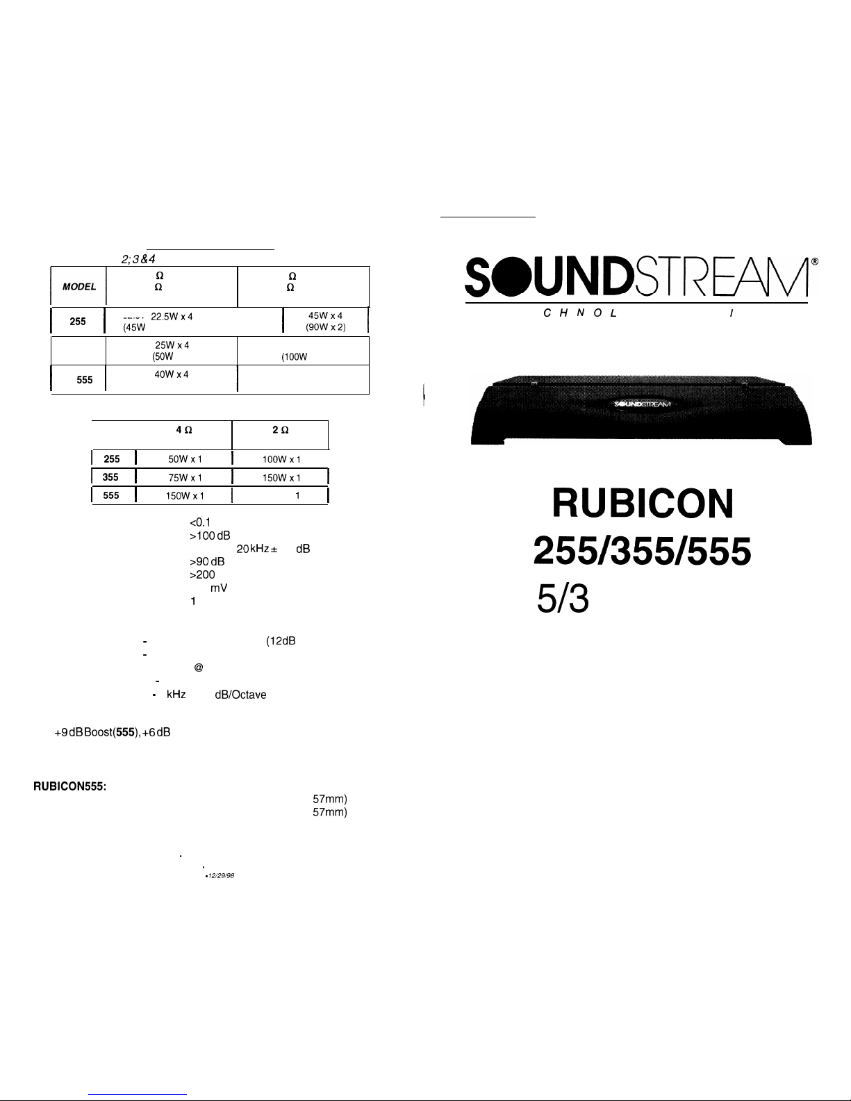
SPECIFICATIONS
Channels I &
2; 3 & 4
4 a Stereo
(8
i2
Bridged)
(12.5 Vdc)
2
Q
Stereo
(4
Q
Bridged)
(14.4 Vdc)
225Wx4
1
255 1 (4kW x2)
1 $“,“x:,
j
355
25Wx4
5ow x4
(5OW
x 2)
(IOOW
x 2)
I
555
I
4owx4
(80W x 2)
80W x4
(160W
x 2)
Subwoofer Channel
I I
MODEL
4Q
2t2
(12.5 Vdc) (14.4 Vdc)
I
255
I
5OWxl
I
100wx1
I
I
355
I
75Wxl
I
15OWxl
I
I
555
I
15OWxl
I
250W x
1
I
THD
co.1
%
Signal to Noise
>I00 dB
Frequency Response
20 Hz to 20 kHz sf 0.5 dB
Stereo Separation
>90 dB
Damping
900
Input Sensitivity
200 mV to 5.0 Volts
Input Impedance
1
Ok Ohms
Crossover Specifications
Low Pass:
55 Hz - 220 Hz at 24 dB/Octave
(12dB
on 255)
High Pass:
50 Hz - 500 Hz at 12 dB/Octave
(Removable SIP @ 150 Hz on 255)
Band Pass (555): 50 Hz - 500 Hz at 12 dB/Octave (Mid-Bass)
50 Hz - 4
kHz
at 12 dB/Octave (Mid)
Hawkins Bass Control
0 to +9 dB
Boost(555), +6 dB
(255,355); Boost Frequency = 45 Hz
(Hawkins Bass Control “IN”)
Sub Sonic filter frequency = 13 Hz
Dimensions (W x D x H)
RUBICON555:
15.0” X 9.8” X 2.25” (381 mm X 250mm X 57mm)
RUBICON355: 13.0” X 9.8” X 2.25” (330mm X 250mm X
57mm)
RUBICON255:
11 .O” X 9.8” X
2.25”
(280mm X 250mm X 57mm)
SWNDSTREAI’V
T E C H N 0
L
0 G
I
E S
RUBICON
5/3
Channel
Power Amplifiers
Owner’s Manual
and
Installation Guide
WWW.SOUNDSTREAM.COM
Folsom - California 95630 USA
ph 916.351.1288 . fax 916.351.0414
rev A - 12/29/98
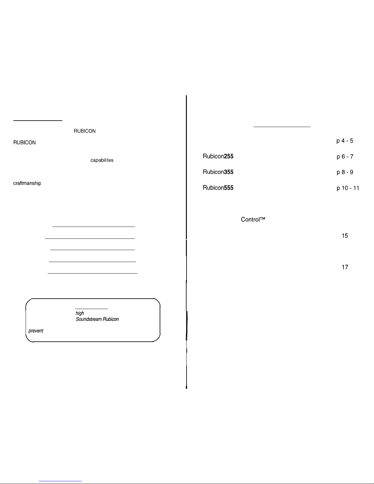
Congratulations!
You now own a Soundstream
RUBICON
amplifier,
the
product of an
uncompromising design and engineering philosophy. Your Soundstream
RUBICON
amplifier will outperform any other amplifier in the world.
To maximize the performance of your system, we recommend that you
thoroughly acquaint yourself with its capabilites and features. Please
retain this manual and your sales receipt for future reference.
Soundstream amplifiers are the result of American innovation and
craftmanship
with the highest quality control standards. When properly
installed, they will provide you with many years of listening pleasure.
Should your amplifier ever need service or replacement due to theft,
please record the following information which will help protect your
investment.
Model and Serial #
Dealer’s Name
Date of Purchase
Installation Shop
Installation Date
f
CAUTION!
Prolonged listening at
high
levels may result in hearing loss.
Even though your
new
Soundstream
Rubiwn amplifier sounds
better than anything you’ve ever heard, exercise caution to
prevenf
hearing damage.
Table of Contents
Design Features
.......................................................
p4-5
Rubicon
Amplifier Diagram
.................................
~6-7
Rubicon
Amplifier Diagram
.................................
p8-9
Rubicon
Amplifier Diagram
.................................
plO-11
Crossover Adjustments
............................................
p 12-13
Hawkins Bass
ControlTM
Theory and Use
................ p 14
Installation: Speaker Output Modes
........................
P
15
Installation: Wiring
...................................................
P 16
lnstal
lnstal
lation: Mounting
..............................................
P
17
lation:
Level Setting and Front Spoiler..
..........
p 18
Sample System Diagrams
. . . . . . . . . . . . . . . . . . . . . . . . . . . . . . . . . . . . . . . .
p 19-26
Protection Circuitry, Service and Troubleshooting . . . p 27
Specifications
. . . . . . . . . . . . . . . . . . . . . . . . . . . . . . . . . . . . . . . . . . . . . . . . . . . . . . . . . . .
P 28
3
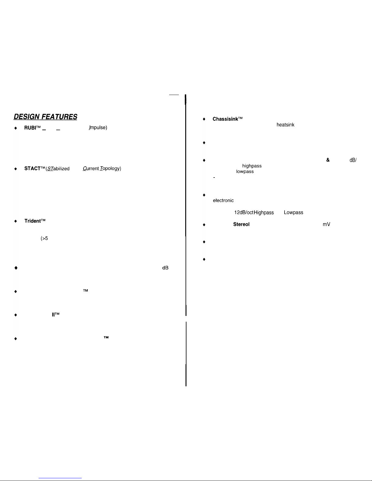
RUBITM
(Rapid-Use Branched
jmpulse)
This new proprietary power
-
-
supply topology eliminates “power sags” during low frequency reproduction by rapidly increasing the duty cycle, stabilizing the power supply and allowing it to deliver the power required when reproducing low
frequencies. Also, greater reserve gate power is stored for low voltage situations that occur during extreme conditions.
STACTTM (STabilized
Apex
Qrrent _Topology)
Reduces power supply stress by 50%. Typical designs degrade the stereo image due to
phase reversal of even-order harmonic distortion that occurs between
the inverted channels. In the STACT design, inversion is done at the
power amplifier drive stage. Since the fully symmetrical power amplifier produces no even-harmonic distortion itself and all preamplifier
circuitry is run completely in-phase, no even harmonic distortion phase
reversal occurs.
TridentTM
Protection
Topology
provides three types of protection:
1. Output protection against short circuits or improper loads.
2.
Ground fault detection: Shuts down the amplifier when a significant
voltage
(~5
Volts) fluctuation occurs between electrical (turn-on lead)
and battery ground.
3. Thermal Protection: Puts the amplifier into thermal rollback or shuts
the amplifier down in extreme thermal conditions.
Hawkins Bass Control
provides a focused subwoofer boost (O-9
dB
at 45 Hz) and routes otherwise wasted amplifier power back to the
audible bandwidth.
Harmonic Bass Alignment
TM
The 2nd and 3rd order harmonic peaks
are critically aligned to fundamental peaks at low frequencies. This
produces tighter, more accurate bass reproduction.
Drive Delay
llTM
Amplifier section powers up 2 to 3 seconds after the
power supply eliminating turn-on pops. Turn off process is reversed:
Amplifier section turns off first, followed by the power supply.
Dynamically Optimized
Power Grid
TM
Power grid is evenly distrib-
uted between primary and secondary power supplies, providing
greater
dynamics and improved RF filtering.
4
ChassisinkTM
All transistors are ideally located and sandwiched between the circuit board and the heatsink to provide cool efficient amplifier operation.
Differentially Balance RCA Input
eliminates ground loop related noise
in the audio path.
Continuously Variable Crossover Networks (355 & 555):
12 dB/
Octave 2-way
highpass
crossover, variable from 65 to 220 Hz and 24
dB/Octave
lowpass
crossovers variable from 30 to 120 Hz. 555 on/y
-
12 dB/Octave 3-way crossover which can be selected for mid-bass
(65 to 500 Hz) or midrange (65 to 4,000 Hz) operation.
Built-in Staggered S.I.P. Crossover Network (255)
Built-in two-way
electronic
crossover is designed to send high pass information to
channels 1-4 of the amplifier and send low pass to channel 5 of the
amplifier.
12dB/oct Highpass
and
Lowpass
crossovers.
Flexible
Stereo1
Input Level Control allows 200 mV to 5 V input
sensitivity.
Symmetrical Discrete Balanced Class A Drive Boards Auto-ad-
just for linear performance while driving low impedance loads.
Removable Front Spoiler allows for stealth installation of RCA,
Speaker and Power wiring.
‘.
‘.
16
1.
2.
3.
4.
5.
6.
7.
8.
9.
10.
11.
12.
13.
14.
15.
16.
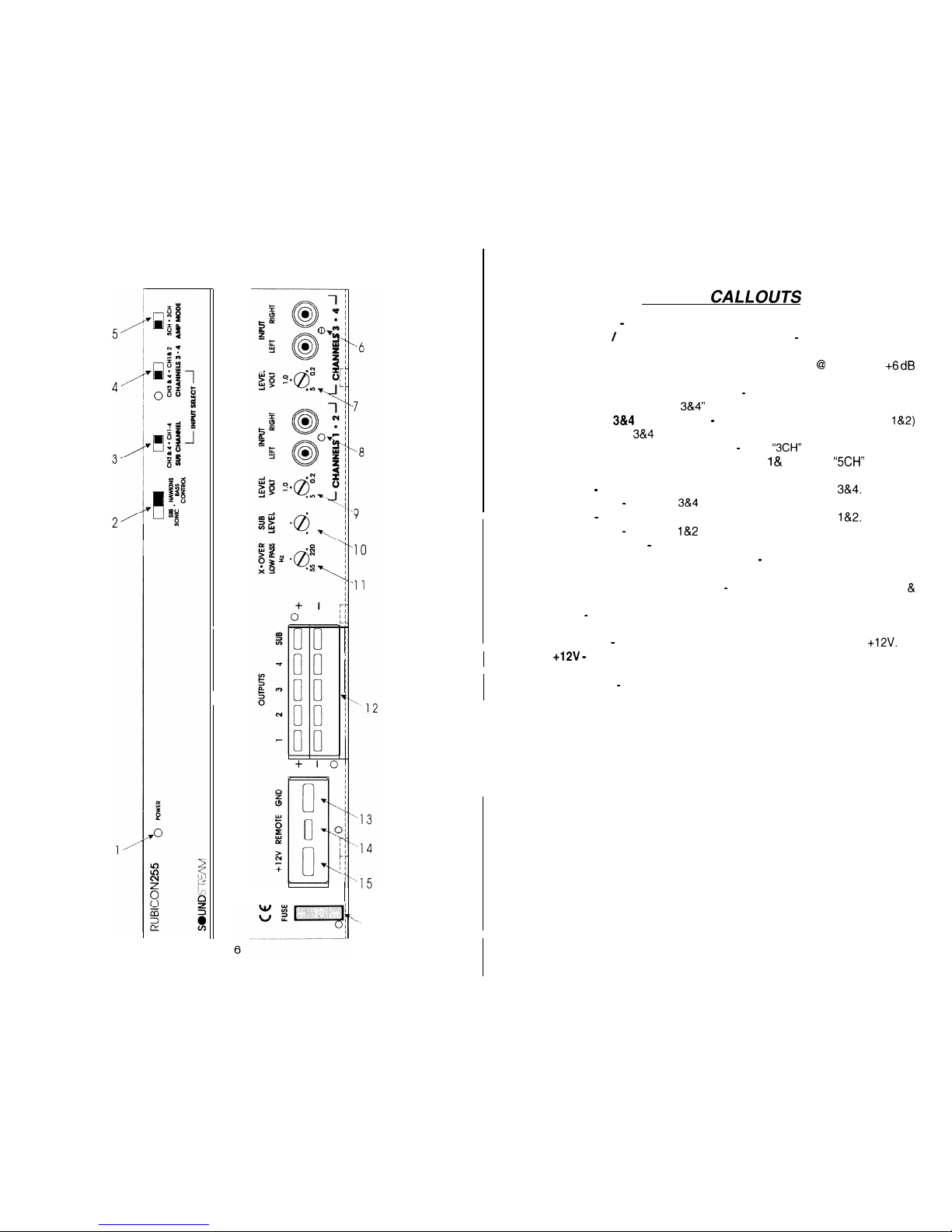
KEY TO
CALLOUTS
Power LED
-
Indicates amplifier power.
Subsonic / Hawkins Bass Control Switch
-
Select “SUB SONIC” to
engage the Sub Sonic filter at 13 Hz. Select “HAWKINS BASS CONTROL”
to engage the subwoofer channel’s high pass filter @I 45 Hz with +6
dB
boost for optimum bass.
Subwoofer Channel Input Select
-
Selectable inputs; “CH l-4” for non-
fading bass control, “CH 3&4” for front to rear fading bass control.
Channels
3&4
Input Select
-
Selectable inputs from internal (CH
l&2)
or external (CH
38~4
local RCA inputs).
Amp Mode Switch (Channels 1-4)
-
Select “3CH” for bridged mono output
in 3 channel operation (use input channels
1 &
2). Select “5CH” for stereo
output in 5 channel operation.
Inputs
-
Right and left channel RCA inputs for channels
3&4.
Input Level
-
Channels
3&4
input level control.
ltiputs
-
Right and left channel RCA inputs for channels l&2.
Input Level
-
Channels
l&2
input level control.
Sub Input Level
-
Subwoofer channel input level control.
Low Pass Filter Control Adjustment
-
(Subwoofer Channel) crossover
frequency control for the internal low pass filter.
Speaker Connection Terminal
-
Speaker connections for CH l-4
&
Subwoofer Channel.
GND - Main ground connection.
Bolt to a clean chassis point in the ve-
hicle.
REMOTE
-
Remote turn-on input from the head unit. Accepts +12V.
+12V -
Connected to a fuse or circuit breaker, then to the battery’s posi-
tive terminal.
Main Fuse
-
Main power supply fuse.
8
9
10
,-l
1
16
1.
2.
3.
4.
5.
6.
7.
8.
9.
10.
11.
12.
13.
14.
15.
16.
17.
18.
19.
20.
21.
22.
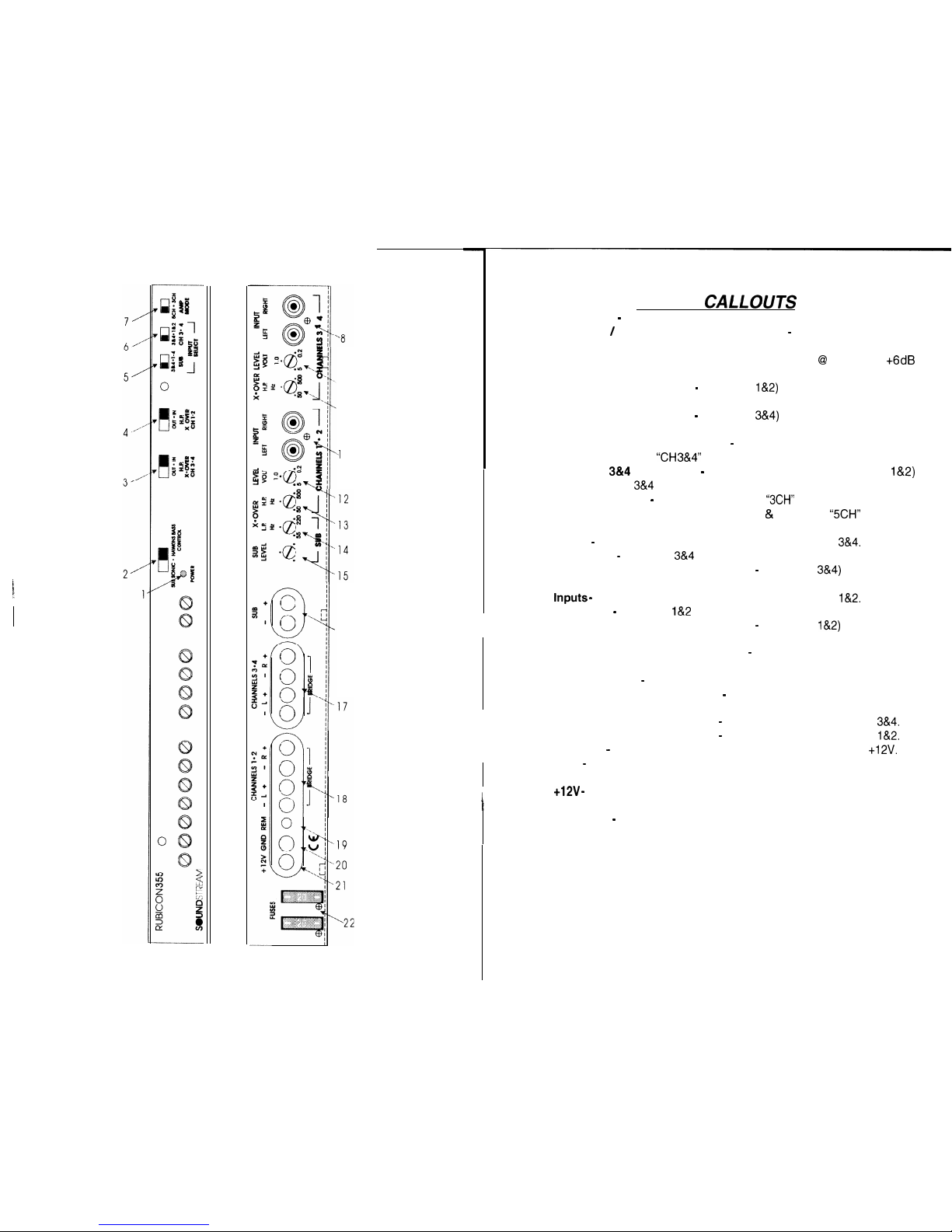
KEY TO
CALLOUTS
Power LED - Indicates amplifier power.
Subsonic / Hawkins Bass Control Switch - Select “SUB SONIC” to
engage the Sub Sonic filter at
13
Hz. Select “HAWKINS BASS CONTROL”
to engage the subwoofer channel’s high pass filter @ 45 Hz with +6
dB
boost for optimum bass.
High Pass XOVER Switch - (Channels l&Z) Select “IN” for use with the
internal crossover or “OUT” for use with external crossover.
High Pass XOVER Switch - (Channels
3&4)
Select “IN” for use with the
internal crossover or “OUT” for use with external crossover.
Subwoofer Channel Input Select - Selectable inputs; “CH 1-4” for non-
fading bass control,
“CH 3&4”
for rear fading bass control.
Channels
3814
Input Select - Selectable inputs from internal (CH
l&2)
or external (CH
3&4
local RCA inputs).
Amp Mode Switch - (Channels 1-4) Select
“3CH”
for bridged mono output
in 3 channel operation (use channels 1 & 2). Select
“5CH”
for stereo
output in 5 channel operation.
Inputs - Right and left channel RCA inputs for channels
3&4.
Input Level - Channels
3&4
input level control.
High Pass Filter Control Adjustment - (Channels
3&4)
crossover fre-
quency control for the internal high pass filter.
tnputs -
Right and left channel RCA inputs for channels
l&2.
Input Level
-
Channels
l&2
input level control.
High Pass Filter Control Adjustment - (Channels
l&2)
crossover fre-
quency control for the internal high pass filter.
Low Pass Filter Control Adjustment - (Subwoofer Channel) crossover
frequency control for the internal low pass filter.
Sub Input Level - Subwoofer channel input level control.
Speaker Connection Terminal
-
Speaker connections for Subwoofer
Channel.
Speaker Connection Terminal - Speaker connections for Ch’s
3&4.
Speaker Connection Terminal - Speaker connections for Ch’s
l&2.
REMOTE - Remote turn-on input from the head unit. Accepts
+12V.
GND - Main ground connection.
Bolt to a clean chassis point in the ve-
hicle.
+12V -
Connected to a fuse or circuit breaker, then to the battery’s posi-
tive terminal.
Main Fuse - Main power supply fuses.
 Loading...