

Soundstream Reference Series 405S Installation Manual
20
SOUNDSTREAM TECHNOLOGIES
120 Blue Ravine Road Folsom California 95630 USA
ph 916.351.1288 fax 916.351.0414
rev B - 4.17.96
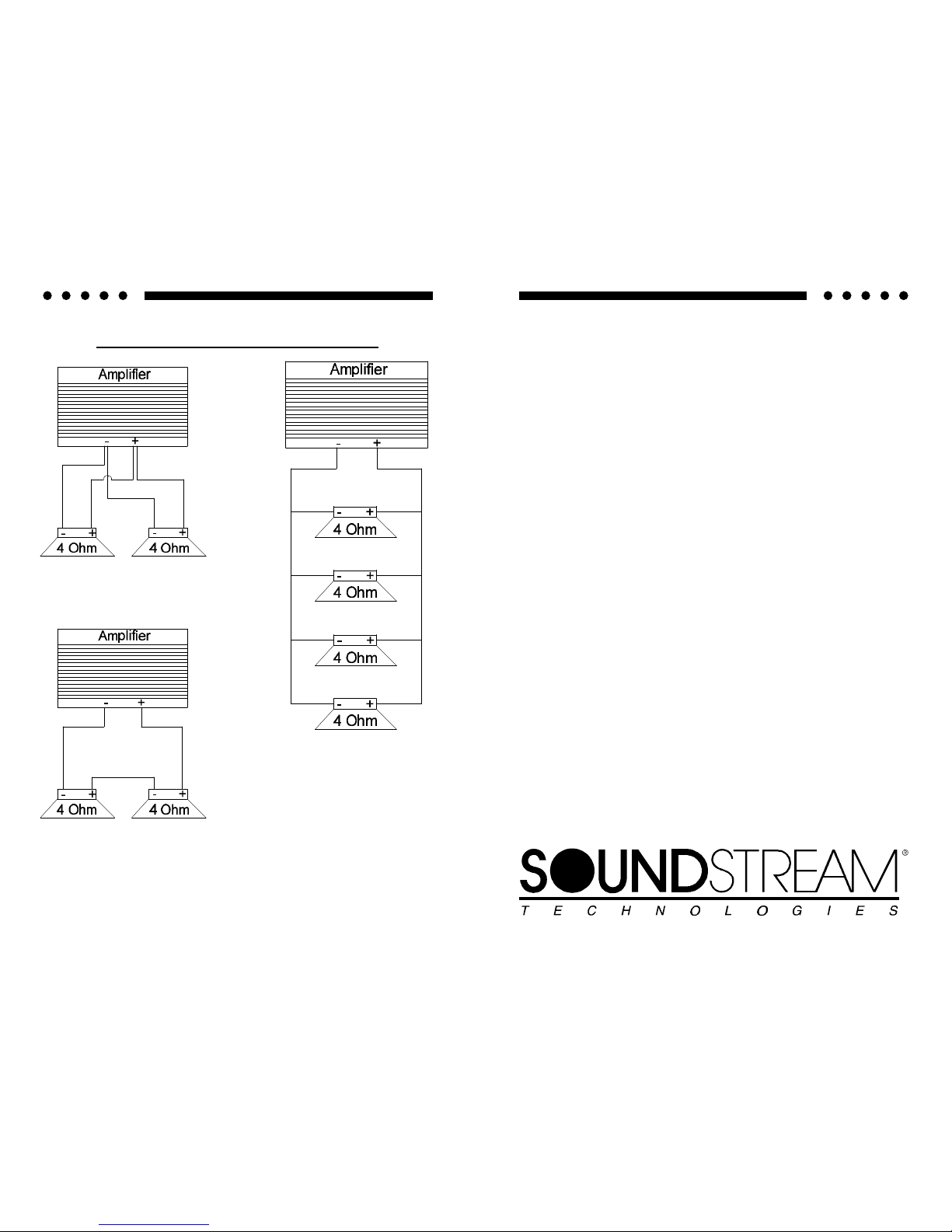
SERIES AND PARALLEL WIRING
2-4 ohm drivers in parallel
= 2 ohms
2-4 ohm drivers in series
= 8 ohms
4-4 ohm drivers in parallel
=1 ohm
1
REFERENCE
405s
5/3 Channel
Power Amplifier
OWNERS MANUAL
AND
INSTALLATION GUIDE
2
CONGRATULATIONS!
You now own the REFERENCE405s Amplifier, the product of an
uncompromising design and engineering philosophy. Your
Soundstream REFERENCE405s amplifier will outperform any other
amplifier in the world.
To maximize the performance of your system, we recommend that you
thoroughly acquaint yourself with its capabilities and features. Please
retain this manual and your sales and installation receipts for future
reference.
Soundstream amplifiers are the result of American craftsmanship and
the highest quality control standards, and when properly installed, will
provide you with many years of listening pleasure. Should your
amplifier ever need service or replacement due to theft, please record
the following information, which will help protect your investment.
Model and Serial # ____________________________________
Dealer’s Name _______________________________________
Date of Purchase _____________________________________
Installation Shop ______________________________________
Installation Date ______________________________________
CAUTION!
Prolonged listening at high levels may result in hearing loss. Even
though your new Soundstream REFERENCE405s amplifier sounds
better than anything you’ve ever heard, exercise caution to prevent
hearing damage.
19
SPECIFICATIONS
THD <0.1%
Signal to Noise >100 dB
Frequency Response (Ch's 1-4):
20 Hz to 20 kHz ± 0.5 dB
Frequency Response (Sub Ch):
20 Hz to 400 Hz ± 0.5 dB
Stereo Separation >90 dB
Damping >200
Input Sensitivity (Ch 1-4):
200 mV - 5.0 V
Input Sensitivity (Subwoofer Ch):
80 mV - 5.0 V
Input Impedance
12 kΩ
Crossover Specifications
High Pass (Channels 1 - 4):
12 dB/octave, continuously variable from 60 to 240 Hz
Low Pass (Subwoofer Channel):
24 dB/octave, continuously variable from 30 to 120 Hz
W x D x H:
15.0” x 9.8” x 2.25”
Dimensions
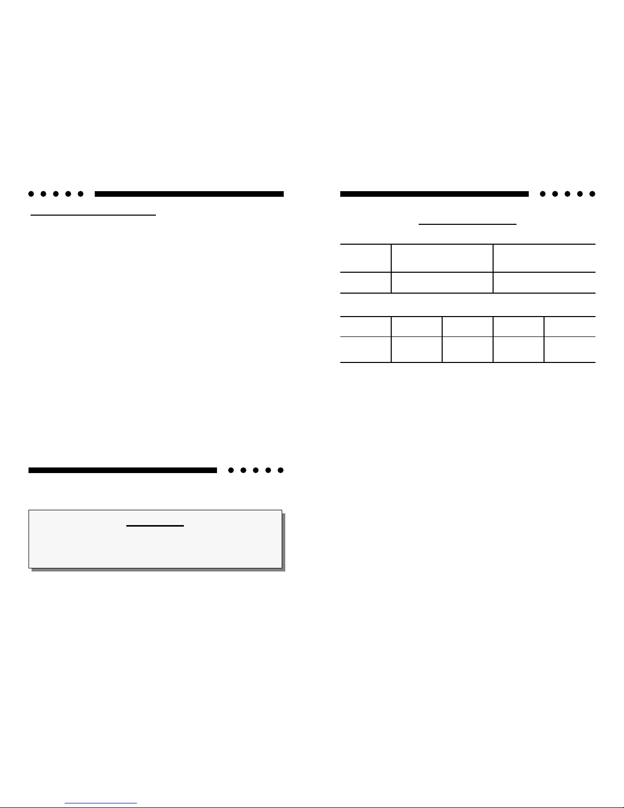
REFERENCE405s - - Channels 1 & 2, 3 & 4
POWER
4 Ω Stereo
(8 Ω Bridged)
(12 Volts)
2 Ω Stereo
(4 Ω Bridged)
Watts
25 Watts x 4 50 Watts x 4
POWER
4 Ω
(12 Volts)
2 Ω 1 Ω 1/2 Ω
High Power
100 Watts 200 Watts 240 Watts n/a
High Current
50 Watts 100 Watts 200 Watts 240 Watts
REFERENCE405s - - Subwoofer Channel

18
PROTECTION CIRCUITRY
Your REFERENCE405s amplifier is protected against both overheating and
short circuits by means of the following circuits:
• Main power supply fuses
• Circuit breakers on channels 1,2,3 & 4
• Smart Power Supply Thermal Rollback activating at 85°C
• A fail-safe thermal protection circuit activating at 95°C.
Your amplifier also incorporates an innovative Fault Diagnosis system that
identifies a blown power supply fuse.
NOTE: If you experience blown main power supply fuses, DO NOT increase
values beyond the original fuse value! Doing so will void your warranty and
TROUBLESHOOTING
PROBLEM CAUSE
No sound and LEDs
are not lit
• no power or ground at amp
• no remote turn-on signal
• blown fuse near battery
Fault LED is lit
• amp power supply fuse is blown or missing
Repeatedly blown
amp fuse, frequent
activation of Smart
Power Supply Circuit
• check speaker configuration, amp may be in
“High Power” mode, put amp into “High Current” mode if speaker load is less than 1 ohm
(see p.8, “Setting High Power/High Current
Switch”)
• speaker or leads may be shorted
• verify adequate amplifier ventilation
Channels 1,2,3 or 4
experiencing intermittent output
• activation of the internal circuit breakers.
• check to make sure channels 1-4 are driving a
2 ohm per channel load or greater
• speaker or leads may be shorted
SERVICE
Your Soundstream REFERENCE405s amplifier is protected by a limited
warranty. Please read the enclosed warranty card.
3
TABLE OF CONTENTS
Design Features .................................................................4 - 5
REFERENCE405s Diagram ...............................................6 - 7
Setting the High Power / High Current Switch ......................... 8
Selecting Input Modes ............................................................. 9
Wiring & Wiring Diagram ................................................10 - 11
Installation and Mounting ...................................................... 12
Level Setting ......................................................................... 13
Crossover Adjustments ......................................................... 14
AIRBASS™ ........................................................................... 14
System Installation Diagrams ..........................................15 -17
Protection Circuitry ................................................................ 18
Troubleshooting .................................................................... 18
Service .................................................................................. 18
Specifications ........................................................................ 19
 Loading...