

Soundstream Reference Series 1000S, Reference 500S, Reference 700S Installation Manual
24
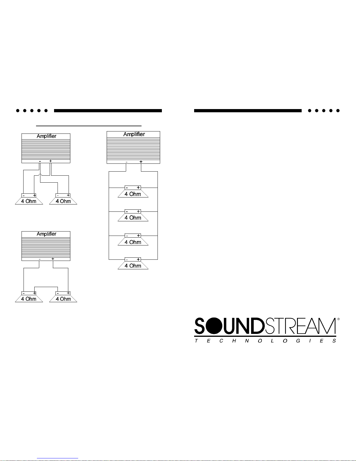
SERIES AND PARALLEL WIRING
2-4 ohm drivers in parallel
= 2 ohms
2-4 ohm drivers in series
= 8 ohms
4-4 ohm drivers in parallel
=1 ohm
SOUNDSTREAM TECHNOLOGIES
120 Blue Ravine Road Folsom California 95630 USA
ph 916.351.1288 fax 916.351.0 414
rev C - 5.01.96
1
REFERENCE
500s
700s
1000s
Power Amplifiers
OWNERS MANUAL
AND
INSTALLATION GUIDE
2
CONGRATULATIONS!
You now own the REFERENCE Amplifier, the product of an
uncompromising design and engineering philosophy. Your
Soundstream REFERENCE amplifier will outperform any other
amplifier in the world.
To maximize the performance of your system, we recommend that you
thoroughly acquaint yourself with its capabilities and features. Please
retain this manual and your sales and installation receipts for future
reference.
Soundstream amplifiers are the result of American craftsmanship and
the highest quality control standards, and when properly installed, will
provide you with many years of listening pleasure. Should your
amplifier ever need service or replacement due to theft, please record
the following information, which will help protect your investment.
Model and Serial # ____________________________________
Dealer’s Name _______________________________________
Date of Purchase _____________________________________
Installation Shop ______________________________________
Installation Date ______________________________________
CAUTION!
Prolonged listening at high levels may result in hearing loss. Even
though your new Soundstream REFERENCE amplifier sounds better
than anything you’ve ever heard, exercise caution to prevent hearing
damage.
23
SPECIFICATIONS
THD
<0.1%
Signal to Noise
>100 dB
Frequency Response
20 Hz to 20 kHz ± 0.5 dB
Stereo Separation
>90 dB
Damping
>200
Input Sensitivity
200mV - 2.0V, or 500mV to 5.0V
Input Impedance
10K ohms
Crossover Specifications
Low Pass: 45 - 180 Hz at 12 dB/Octave
High Pass: 45 - 180 Hz at 12 dB/Octave
LSE.Q (REFERENCE1000s)
0.7 - 2.8 Q (0 TO +9 dB), adjustment from 30 to 60 Hz
Dimensions (W x D x H)
REFERENCE500s: 11.0” x 9.8” x 2.25”
REFERENCE700s: 12.25” x 9.8” x 2.25”
REFERENCE1000s: 16.0” x 9.8” x 2.25”
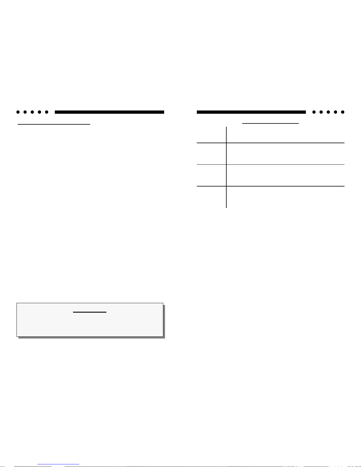
POWER
4 Ω Stereo
(8 Ω Bridged)
(12 Vdc)
2 Ω Stereo
(4 Ω Bridged)
1 Ω Stereo
(2 Ω Bridged)
1/2 Ω Stereo
(1 Ω Bridged)
REFERENCE500s
Watts
75 x 2
(150 x 1)
150 x 2
(300 x 1)
250 x 2
(500 x 1)
250 x 2
(500 x 1)
REFERENCE700s
Watts
125 x 2
(250 x 1)
250 x 2
(500 x 1)
350 x 2
(700 x 1)
350 x 2
(700 x 1)
Watts
200 x 2
(400 x 1)
400 x 2
(800 x 1)
500 x 2
(1000 x 1)
500 x 2
(1000 x 1)
REFERENCE1000s

22
TROUBLESHOOTING
PROBLEM CAUSE
No sound and power LED is not lit
• No power or ground at amp
• No remote turn-on signal
• Blown fuse near battery
No sound, a power LED is lit, and
the AIRBASS™ option has not
been added.
• No signal input
• The AIRBASS™ switch is in the
"IN" position. Move it to the
"OUT" position
Fault LED is lit
• Amp power supply fuse is blown
or missing
Repeatedly blown amp fuse, frequent activation of Smart Power
Supply Circuit
• Speaker or leads may be shorted
• Verify adequate amplifier ventila-
tion
Not enough input sensitivity while
using the Balanced input
• Be sure both Left and Right Input
Signal Switches are set to the
"BAL" position
Left and Right Input Overload indicators lighting
• Input signal level is too high - readjust input gains, or select the
0.5-5V input signal level range
Alternator whine while using Unbalanced RCA inputs
• Make sure the Right Input Signal
Switch is in the "UNBAL" position.
• Try the Left Input Signal Switch
in the "BAL" and "UNBAL" position: leave the switch in the quietest position. This will not effect
the performance of the amplifier.
SERVICE
Your Soundstream REFERENCE amplifier is protected by a limited warranty.
3
TABLE OF CONTENTS
Design Features .................................................................4 - 5
Reference500s Diagram ....................................................6 - 7
Reference700s Diagram ....................................................8 - 9
Reference1000s Diagram ..............................................10 - 11
High Power / Auto High Current™ Power Supply Design ..... 12
Protection Circuitry ................................................................ 12
Crossover Adjustments ......................................................... 13
AIRBASS™ ........................................................................... 13
LSE.Q Theory and Use ..................................................14 - 15
Selecting Input Modes ........................................................... 16
Balanced / Unbalanced Input ................................................ 17
Wiring & Wiring Diagram ................................................ 18 - 19
Installation and Mounting ...................................................... 20
Level Setting ......................................................................... 21
Troubleshooting .................................................................... 22
Service .................................................................................. 22
Specifications ................................................................ ....... 23

4
DESIGN FEATURES
• Uncompromising Design and Construction including mil-spec
glass epoxy circuit boards and high current custom gold-plated solid
brass connections that will accept up to 4 gauge power/ground wire.
• Auto High Current™ - Soundstream’s newest exclusive circuit which
automatically customizes your amplifier to its particular application—
High Current, low impedance loads (multiple subwoofers, less than 2
ohms mono) or High Power, higher impedance loads (2 ohms mono
and up).
• Coherent StereoTM/Mixed Mono selection for either “pure” stereo
operation or mixed mono for simultaneous stereo and mono.
• ChassisinkTM Darlington Power Array - Soundstream’s
“overbuilding” of the output section incorporates multiple output
transistors instead of a few for faster, stronger power delivery. The
transistors are sandwiched between the circuit board and the heatsink
in a design called ChassisinkTM to ensure cool, efficient amplifier
operation.
• PowerGrid Power Supply Design - All power supply components
are located near one another, connected by thick, wide PCB traces,
which ensures rapid, high current delivery. The entire power supply is
isolated on one side of the circuit board while the audio stage is
located opposite it, guaranteeing minimal noise.
• Ultra-Low ESR Capacitance Bank - Multiple small input power
capacitors are used to provide a lower ESR (Equivalent Series
Resistance), which means more power in and out faster.
• Smart Thermal Rollback - Most amplifiers shut off when they get too
hot. In the unlikely event the REFERENCE amplifier reaches 85° C,
it will gradually roll back its average power (without affecting the
dynamics). Once the amplifier has cooled off, it returns to full power
output. If overheating should continue, a second thermal sensing
protection circuit will shut off the amplifier if the heatsink reaches 95°
C.
• Fault Monitor LED on the top panel notifies you of blown power
supply fuses.
• 1/2 ohm Drive Ability - The REFERENCE amplifiers are designed to
21
LEVEL SETTING
The input levels are adjusted by means of the individual channel input level
controls located on the front of the amplifier. This is a unique dual-stage
circuit that adjusts both level and gain. This topology maintains better Signal
to Noise ratios even when using sources with minimal output.
In the ideal situation, all components in the audio system reach maximum
undistorted output at the same time. The reason is because an amplifier will
only make what comes into it bigger. So, if you send it a distorted signal from
the head unit, the amplifier is going to amplify distorted information. The
same thing holds true if an outboard processor or crossover begins to distort
before you have maximum output from the amplifier. By setting all
components to reach clipping at the same time, you can maximize the output
of your system. For the REFERENCE amplifiers, follow the following steps for
the quickest, easiest means of setting the levels.
INSTALLATION STEP 5
1. Turn the amp’s input levels to minimum position (fully counterclockwise).
2. Begin with the input level switch in the 0.5 - 5.0 Volt position.
3. Set source unit volume to approximately 3/4 of full volume.
4. While playing dynamic source material, slowly increase the amplifier’s
input level until a near maximum undistorted level is heard in the
system.
If your preamplifier / source unit has an extremely high output level, be sure to
pay attention to the clipping indicators located on the top of the amplifier.
These indicators will notify you if you are clipping the PREAMPLIFIER stage of
the amplifier. If the amplifier's output is distorted and the clipping lights are
not blinking, you are most likely clipping the OUTPUTS of the amplifier, or
driving the speaker to distortion.
 Loading...