

Soundstream REFERENCE 300SX Owner's Manual And Installation Manual
l
l
l
l
l
LLI
0
Z
LLl
P
LLI
II
Lll
P
3
0
0
cr)
Q
E
a
I---
m
n
CONGRATULATIONS!
You now own the REFERENCE Amplifier, the product of an
uncompromising design and engineering philosophy. Your
SoLndstream
REFERENCE amplifier will outperform any other amplifier in the world.
To madmize the
pedorrnance
of your system, we recommend that you
thoroughly acquaint yourself with its capabilities and features. Please retain
this manual and your sales and installation receipts for future reference.
Soundstream amplifiers are the result 01 American craftsmanship and
the
highest quality control standards, and when
properly
installed
will
provide
you with many years of listening pleasure. Should your amplifier ever need
service or replacement due to theft, please record the following information,
which will help protect
your
investment.
Model
and Serial #
Dealer’s Name
Date of Purchase
Installation Shop
l
0e.e
DESIGN FEATURES
. Uncompromising Design and Construction - including
mil-spec
glass
epoxy circuit boards and high
current
custom gold-plated solid brass
connections that will accept up to 4 gauge power/ground wire.
. Hlgh PowerRligh Current CapabIlity - Soundstream’s exclusive circuit
which permits customization of your amplifier to its particular
application-high current, low impedance loads (multiple subwoofers, less
than 2 ohms mono) or High Paver, higher impedance loads (2 ohms mono
and up).
. Coherent
StereoTYIMlxed
Mono - selection for either “pure” stereo
operation or mixed mono for simultaneous stereo and mono.
2
Chassisink”
Darlington Power Array -
Soundstream’s
“overbuilding” of
the
output section incorporates multiple
outpul
transislors instead of a few
for faster, stronger power delivery. The transistors
are
sandwiched
between the circuit board and
the heatsink
in a design called
Chassisir&TM
to ensure cool. efficient amplifier operation.
PowerGrid Power Supply Design -
All
power supply components are
located near one another. connected by thick. wide PCB traces. which
ensures rapid, high current delivery. The entire power supply is isolated on
one side of the
circuit
board while the audio
stage
is located opposite if,
guaranteeing minimal noise
Ultra-Low ESR Capacitance Bank-Multiple small input power capacitors
are
used
to provide a lower ESR (Equivalent Series Resistance), which
means more power
in and
auf
faster.
Smart
Thermal
Rollback - Most amplifiers
shut
off when they get too hot.
In the unlikely event the
REFERENCE300sx
amplifier reaches 85” C, it will
gradually roil back its average power (without affecting the dynamics).
Once the amplifier has cooled off, it returns to full power
oulput.
If
overheating should continue, a second thermal sensing protection circuit
will shut off the amplifier if the
heatsink
reaches 95” C.
Unregulated Power Supply 4 ohm power ratings are measured at 12
volts, meaning substantially greater oulpui in the real world when the
vehicle is funning, where voltages range from 13.2 to 14.4 volts.
l
Fautl
Monitor LED - on
the
top panel notifies you of blown power supply
fuses.
l
l/2
ohm Drlve
Abiiliy
-The REFERENCE amplifiers are designed to drive
virtually any load-all the way down to
l/2
ohm stereo (1 ohm mono).
l Dual Discrete Class A Drive Stages
.
Over six times the drive current of
most amps, which maintains
perfomlance
into low impedance loads.
l Drive
DelayTH
Muted
Turn-oWofl
Circuit .
A unique circuit which
completely eliminates any amplifier-related
turn-on/off
noises.
l Flexible hput Sensitivity
-
accepts voltages from 200 mV to 5.0 V,
penitling
maximum output from the amplifier with virtually any source.
l Differential Balanced input Design
-
for
added
immunity to noise caused
,by
component and vehicle electrical system interaction when using
\Inbalanced
RCA inputs.
3
l
o.0
I
l
eoeo
d
0 0 0
““.a000
0000
i
123
/-
0
0
\
.
0
0
/
SOTlOM
VJEW (PARUALJ
I
I
/ :
1.
2.
3.
4.
5.
6.
7.
0.
9.
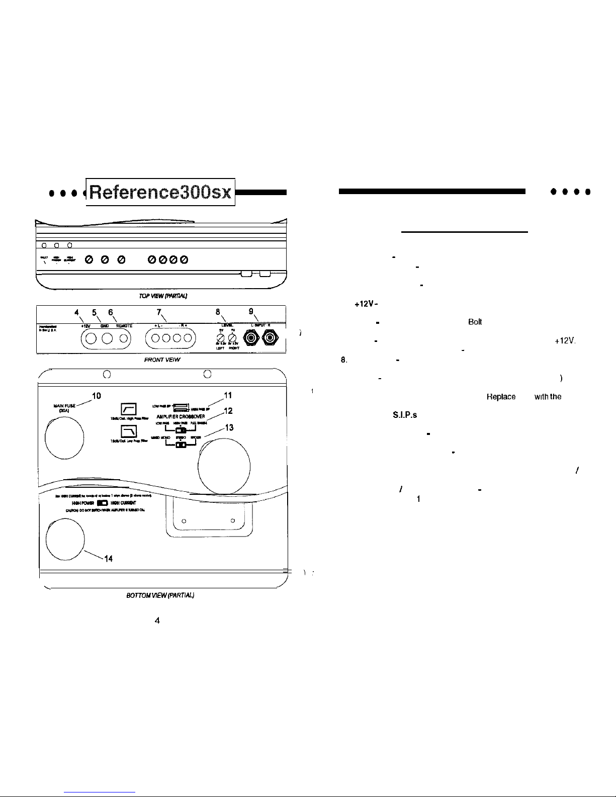
Kev to Caiiouts
Fault LED - Indicates a blown fuse.
High Power LED - Indicates amplifier power on in “High Power’
mode.
High Current LED - Indicates amplifier power on in “High Current”
mode.
+12V -
Connect to a fuse or circuit breaker, then to the batfery’s
positive post.
GND
-
Main ground connection.
Bolt
to a clean chassis ground in
the vehicle.
REM - Remote turn-on input from the head unit. Accepts
+lZV.
Speaker Output Connections - Left and right channels.
Input Level - independent Left and Right channel input level
controls.
Inputs - Right and left channel RCA (Differential Balanced ) inputs;
only right channel input is used in “Mono” mode.
IO. Main Fuse-Main power supply fuse.
Heplace
only
with
the same
value fuse.
11. Crossover
S.1.P.s
-Crossover frequency settings for the amplifier.
See page 9 for more details.
12. Amplifier Crossover - Select high pass, low pass or full range
amplifier operation.
13. Mixed Mono/Stereo/Bridge - Select “Bridge” for bridged mono
operation (use right channel input). Select “Stereo” for coherent
stereo operation. Select “Mixed Mono’ for simultaneous stereo
I
bridged mono operation.
14. High Power I High Current Switch - Use HIGH CURRENT for
loads at or below 1 ohm stereo (2 ohms mono).
CAUTION: DO
NOT SWITCH WHEN AMPLIFIER IS TURNED ON.
4
5
 Loading...