

Soundstream Granite 120.4, Granite 180.6, Granite 60.2 Owners And Installation Manual

SOUNDSTREAM
Granite 60.2,
Granite 120.4 and
Granite 180.6
POWER
AMPLIFIERS
OWNER’S MANUAL &
INSTALLATION GUIDE
CONGRATULATlONS
You now own the Soundstream Granite Amplifier, the result of a unique design and
engineering philosophy.
To maximize the performance of your system, we recommend that you thoroughly
acquaint yourself with its capabilities and features. Please retain this manual and
your sales and installation receipts for future reference.
Soundstream amplifiers are the result of American craftsmanship and the highest
quality control standards, and if properly installed, should provide you with many
years of listening pleasure. Should your amplifier ever need service or replacement
due to theft, please record the following information, which will help protect your
investment.
Model
Serial Number
Dealer’s
Name
Date of Purchase
Installation Shop
Installation Date
CAUTION!
Prolonged listening at high levels may result in hearing loss. Even though your new
Soundstream amplifier sounds better than anything you’ve ever heard, exercise
caution to prevent hearing damage.
DESlGN FEATURES
Handcrafted
in the U.S.A. with mil-spec glass epoxy circuit boards, low-loss con-
nections, gold plated input connectors, and metal film resistors.
Darlington High Current Discrete Output Topology
-
Soundstream’s “overbuild
ing” of the output section incorporates Darlington output devices sandwiched
between the circuit board and the heat sink in a design called
ChassisinkTM
to
ensure cool, efficient amplifier operation.
Mixed Mono Capable so you can simultaneously drive a stereo and mono load
(satellites and subwoofer).
2 Ohm Drive Ability - The Granite amplifiers are designed to drive loads all the
way down to 2 Ohms stereo and 4 Ohms bridged.
Built-in Staggered Asymmetrical Crossovers (Granite 120.4, Granite 180.6)
-
Built-in electronic crossovers are designed to compensate for the acoustics of
the automobile environment. A high pass crossover (at 150 Hz
@
12
dB/octave)
and low pass crossover (at 75 Hz @ 12
dB/octave)
allow you to drive a com-
plete subwoofer and satellite system without the use of passive crossovers.
l Internal Signal Routing (Granite 120.4, Granite 180.6)
-
Permits one pair of
signal cables to drive all 4 channels (Granite 120.4) or two pairs of signal cables
to drive all 6 channels (Granite 180.6).
l Drive Delay Muted
Tunum/off
Circuit
-
a
unique circuit which completely elimi-
nates any amplifier-related turn-on/off noises.
l Flexible Input Sensitivity
-
accepts input voltages from 100 mV to 2.5 V, which
permits maximum output from amplifier with virtually any source unit.
*“Balancing Act” Input Topology
for added immunity to ground loops caused by
component and vehicle electrical system interaction.
Your Granite amplifier comes with a limited warranty. Refer to the enclosed
warranty card for length of warranty and conditions.
SPECIFlCATIONS
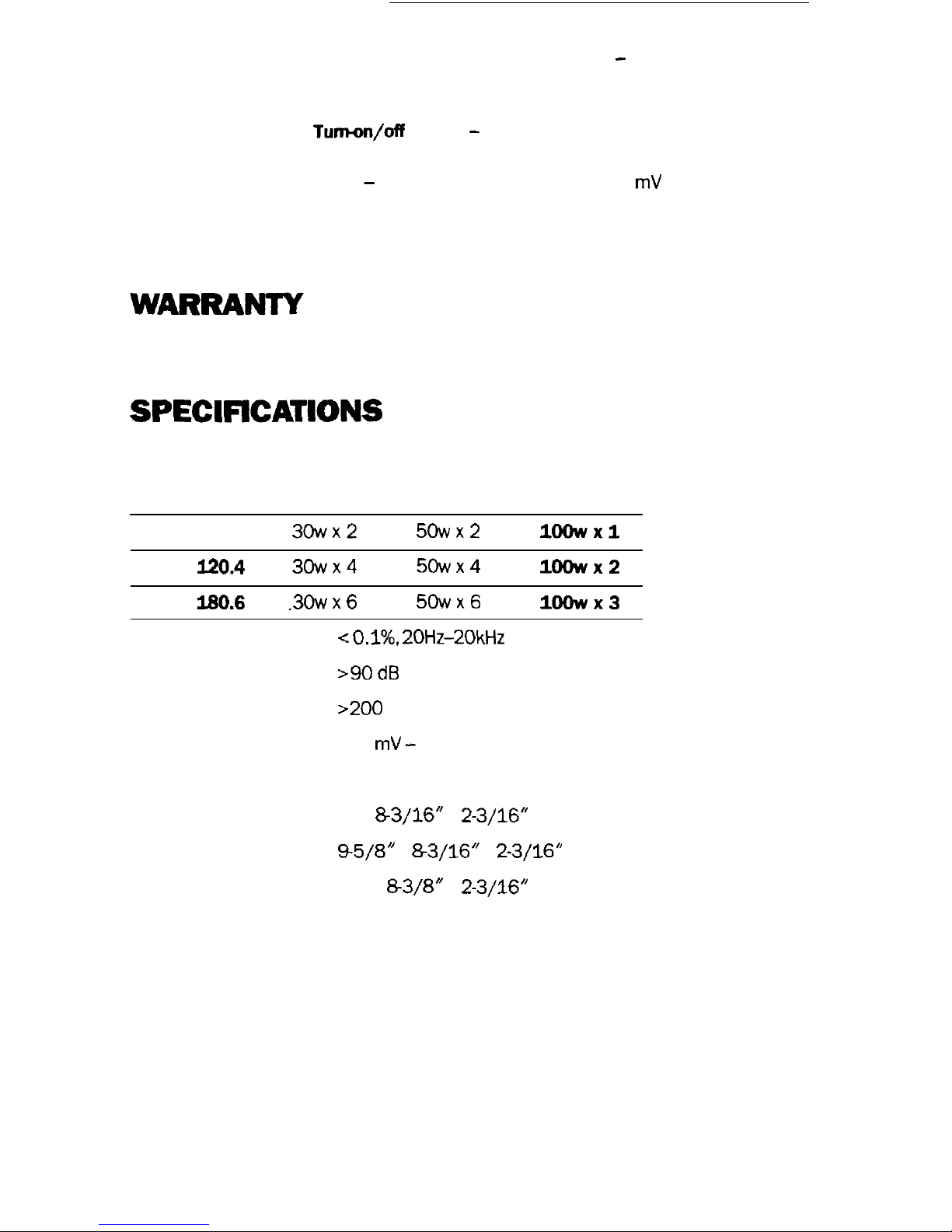
POWER OUTPUT
Power into
Power into
Bridged Power
4
Ohms
2
Ohms
into 4 Ohms
Granite 60.2
3Owx2
5Owx2
loowxl
Granite
120.4
3owx4
5owx4
lOOWx2
Granite 180.6
.3Owx6
50~x6
lOOwx3
THD <
O.l%, 20Hz-20kHz at rated power into 4 ohms
S/N Ratio
>90 dB
Damping Factor
>200
Input Sensitivity 100 mV - 2.5 V
Dimensions (W x D x H)
Granite 60.2 7” x
&3/16”
x
2-3/16”
Granite 120.4
95/8”
x
83/16”
x
2-3/16”
Granite 180.6
12” x
83/8”
x
2-3/16”
2
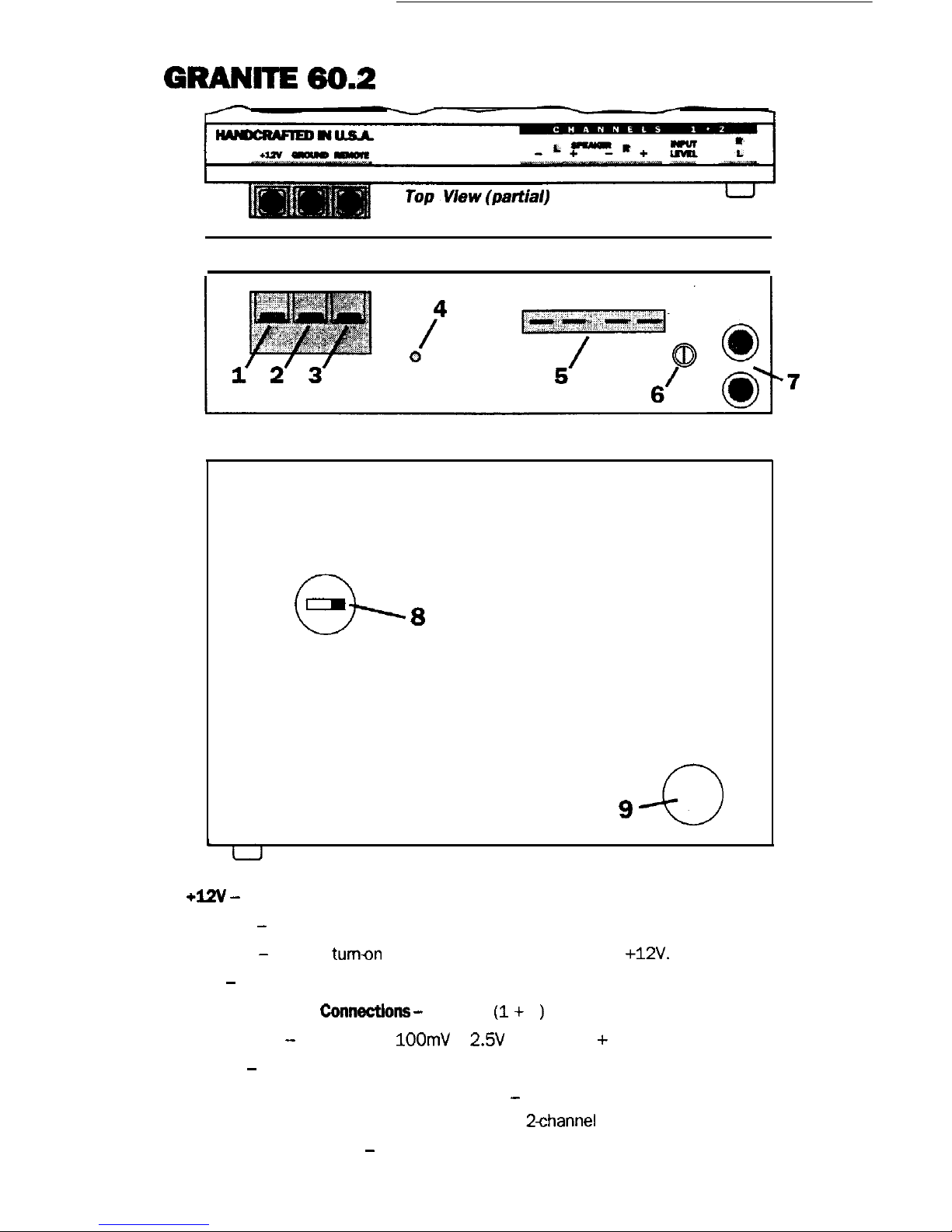
GRANITE
60.2
Side View
MONO STEREO STEREO
o-
.
8
MAIN FUSE
9
-0
Underside
View
1.
+W -
Connected to fuse or circuit breaker, then battery’s positive post.
2. Ground - Main ground connection. Bolt to a clean chassis ground in the vehicle.
3. Remote - Remote
tumon
input from the head unit. Accepts +12V.
4. LED - Indicates amplifier power on.
5.
Speaker Output
ConnectIons -
Channels
(1
+
2
)
6. Input Level - Variable from 100mV to 2.5V (Channels 1 + 2).
7. Inputs - Right and Left Channel inputs; only right channel input used in “Mono” position.
8.
[underside]
Mono/Stereo/Stereo Switch
-
Select “Mono” for bridged operation (only use
right channel input) or either Stereo position for
2channel
Stereo or Mixed Mono operation.
9. [underside] Main Fuse - Main power supply fuse. Replace only with same value.
3
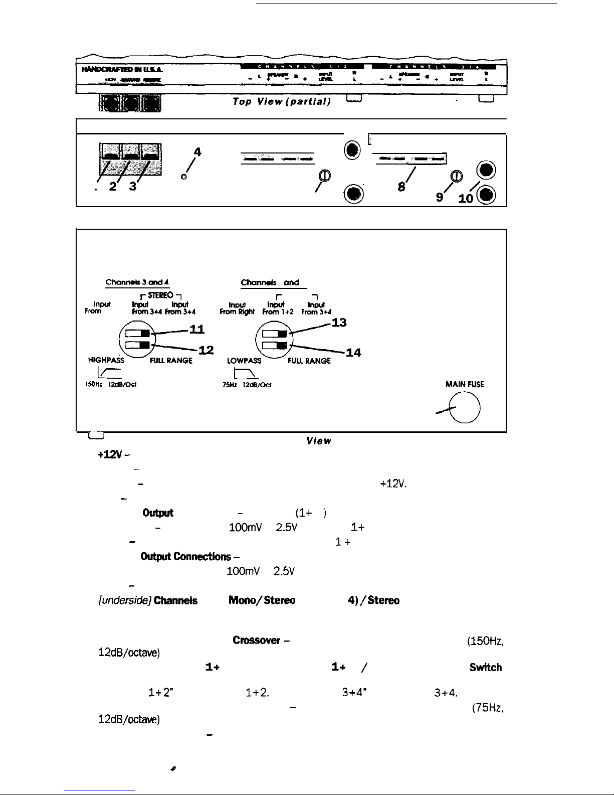
GRANIlE120.4
.->A-
--
0’ --
-,--I
1
5’
6
0
‘7
8
Side View
CflOnllOlS3UldA
Channets 1 and 2
MONO
r~~oi
MONO
r
STEREO
7
twut
tnprt
twut
mm
Right
FKlm3u
ficm3+4
tnpur
tnput
tnwt
FmmRkJht
Ffom1+2
Fmm3+4
15
a
u
L-J Underside View
1. +I2V - Connected to fuse or circuit breaker, then battery’s positive post.
2. Ground - Main ground connection. Bolt to a clean chassis ground in the vehicle.
3. Remote - Remote turn-on input from the head unit. Accepts
+12V.
4. LED - indicates amplifier power on.
5. Speaker
Du@ut
Connections
-
Channels
(1
+
2
)
6. Input Level - Variable from
100mV
to 2.W (Channels
1
+
2).
7. Inputs - Standard RCA style connectors (Channels I+ 2). Right channel only for mono.
8. Speaker
Output
Connections -
(Channels 3 + 4)
9. Input Level -Variable from
1OOmV
to
2.5V
(Channels 3 + 4).
10. Inputs - Standard RCA style connectors (Channels 3 + 4). Right channel only for mono.
11.
[underside]Channels
3 + 4
Mono/Stereo
(input 3 +
4)/Stereo
(input 3 + 4) Switch
MONO position for single channel operation (only right channel is active in Mono). Use
either STEREO input position with RCA inputs from Channels 3 + 4.
12. [underside] Channels 3 + 4
Cnwsover
-
Select either full range or high pass
(150H2,
12dB/octave)
operation.
13. [underside] Channels
1
+
2 Mono/Stereo (input
1
+
2) / Stereo (input 3 + 4)
Switch
MONO position for single channel operation (only right channel is active in Mono). Use
“STEREO
1+2”
for RCA inputs
1+2.
Use “STEREO
3+4”
for RCA input
3+4.
14. [underside] Channels 1 + 2 Crossover - Select either full range or low pass
(75H2,
12dB/octave)
operation.
15. [underside] Main Fuse - Main power supply fuse, replace only with same value.
4
0
GRANITE180.6
u
u
UndersIde View
u
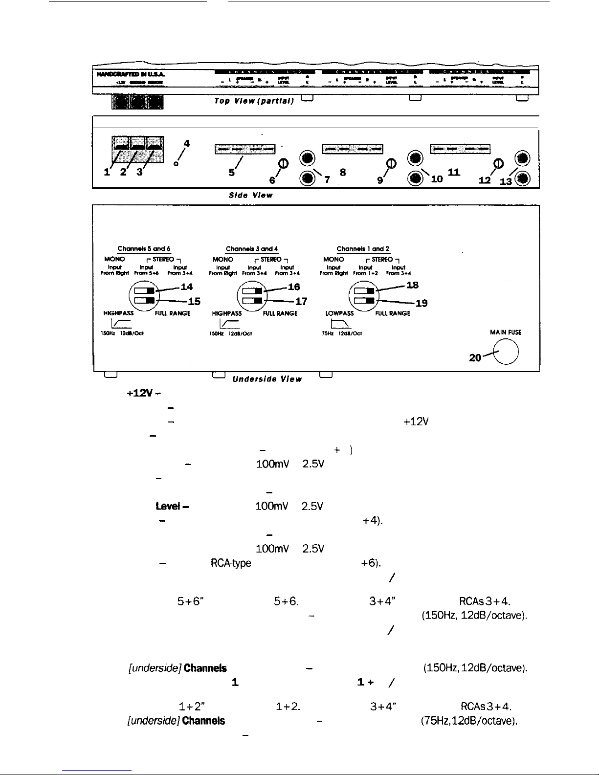
1.
+I2V -
Connected to fuse or circuit breaker, then battery’s positive post.
2. Ground - Main ground connection. Bolt to a clean chassis ground in the vehicle.
3. Remote - Remote turn-on input from the head unit. Accepts +12V
4. LED - Indicates amplifier power on.
5. Speaker Output
Connections - Channels
(1
+
2
)
6. Input Level - Variable from
1OOmV
to 2.5V (Channels 1 + 2).
7. Inputs - Standard RCA-type connectors (Channels
1 +
2). Use only right channel for mono.
8. Speaker Output Connections - (Channels 3 + 4)
9. input
level -
Variable from 100mV to 2.5V (Channels 3 + 4).
10. Inputs - Standard RCA-type connectors (Channels 3
+4).
Use only right channel for mono.
11. Speaker Output Connections - (Channels 5 + 6)
12. Input Level -Variable from
IOOmV
to 2.5V (Channels 5 + 6).
13. Inputs - Standard
RCAtype
connectors (Channels 5
+6).
Use only right channel for mono.
14. [underside] Channels 5 + 6 Mono/Stereo (input 5 + 6) / Stereo (input 3 + 4) Switch
MONO position for single channel operation. (Only right channel is active in Mono) Use
“STEREO
5+6”
for RCA inputs
5+6.
Use “STEREO
3+4”
for input from
RCAs 3+4.
15. [underside] Channels 5 + 6 Crossover - Full range or high pass
(150Hz,12dB/octave).
16. [underside] Channels 3 + 4 Mono/Stereo (input 3 + 4) / Stereo (Input 3 + 4) Switch
MONO position for single channel operation. (Only right channel is active in Mono) Use
either STEREO input position with RCA inputs from Channels 3 + 4.
17.
[undersidejchannels
3 + 4 Crossover - Full range or high pass (150Hz,
12dB/octave).
18. [underside] Channels 1 + 2 Mono/Stereo (input I+ 2) / Stereo (input 3 + 4) Switch
MONO position for single channel operation (only right channel is active in Mono). Use
“STEREO
1+2”
for RCA inputs
1+2.
Use ‘STEREO
3+4”
for input from
RCAs 3+4.
19.
[unde&de]Chann&
1 +
2 Crossover - Full range or low pass (75Hz,
12dB/octave).
20. [underside] Main Fuse - Main power supply fuse, replace only with same value.
5
 Loading...