

Soundstream AirBass, BLT4, DaVinci User Manual

I) A
v
Limited
I
N C
I
Edition
Seven
f
Channel
Balanced Input Amplifier
OWNER’S MANUAL AND
INSTALLATION GUIDE
SOUNDSTREAM@
E
C
N
0
0
G
E
S

CONGRA TULA
TIONS!
You now own
the
Limited Edition
DaVinci amplifier, the product of an uncompromising design and
engineering philosophy. Your Limited Edition DaVinci amplifier will outperform any other amplifier in the
world.
To maximize the performance of your system, we recommend that you thoroughly acquaint yourself with its
capabilities and features.
Please retain this manual and your sales and installation receipts for future
reference.
Soundstream amplifiers are the result of American craftsmanship and the highest quality control standards,
and when properly installed, will provide you with many years of listening pleasure. Should your amplifier ever
need service or replacement due to theft, please record the following information, which will help protect your
investment.
Serial #
Dealer’s Name
Date of Purchase
Installation Shop
Installation Date
2
TABLE OF CONTENTS
Features
. . . . . . . . . . . . . . . . . . . . . . . . .
..~................................~.~..~.~~.........~.....~................................~..........
4-5
DaVinci Diagram
. . . . . . . . . . . . . . . . . . . . . . . . . . . . . . . . . . . . . . . . . . . . . . . . . . . . . . . . . . . . ..-....................................................
6-7
Limited Edition
BLT4TM
Balanced Line Transmitter
. . . . . . . . . . . . . . . . . . . . . . . . . . . . . . . . . . . . . . . . . . . . . . . . . . . . . . . . . . . . . . . .
8-9
Selecting Crossover Modes
......................................................................................................
10
Selecting Input Modes ..............................................................................................................
11
Wiring .......................................................................................................................................
12
Installation and Mounting
. . . . . . . . . . . . . . . . . . . . . . . . . . . . . . . . . . . . . . . . . . . . . . . . . . . . . . . . . . . . . . . . . . . . . . . . . . . . . . . . . . . . . . . . . . . . . . . . . . . . . . . . . .
13
Crossover Adjustments
. . . . . . . . . . . . ..I..............................................................................................
14
.
Level Setting
. . . . . . . . . . . . . . . . . . . . . . . . . . . . . . . . . . . . . . . . . . . . . . . . . . . . . . . . . . . . . . . . . . . . . . . . . . . . . . . . . . . . . . . . . . . . . . . . . . . . . . . . . . . . . . . . . . . . . . . .
.....
15
LSE.Q Subwoofer Equalization Circuitry
. . . . . . . . . . . . . . . . . . . . . . . . . . . . . . . . . . . . . . . . . . . . . . . . . . . . . . . . . . . . . . . . . . . . . . . . . .
..~......
16
A/RBASSTM
Accessory Option
. . . . . . . . . . . . . . . . . . . . . . . . . . . . . . . . . . . . . . . . . . . . . . . . . . . . . . . . . . . . . . . . . . . . . . . . . . . . . . . . . . . . . . . . . . . . . . . . .
17
Sample Systems
. . . . . . . . . . . . . . . . . . . . . . . . . . . . . . . . . . . . . . . . . . . . . . . . . . . . . . . . . . . . . .
..-
I..~............................,..............
18-21
Protection Circuitry, Troubleshooting & Service
. . . . . . . . . . . . . . . . . . . . . . . . . . . . . . . . . .
..-
. . ..-..-...........................
22
Specifications
. . . . . . . . . . . . . . . . . . . . . . . . . . . . . . . . . . . . . . . . . . . . . . . . . . . . . . . . . . . . . . . . . . . . . . . . . . . . . . . . . . . . . . . . . . . . . . . . . . . . . . . . . . . . . . . . . . . . . . . .
...
23
3
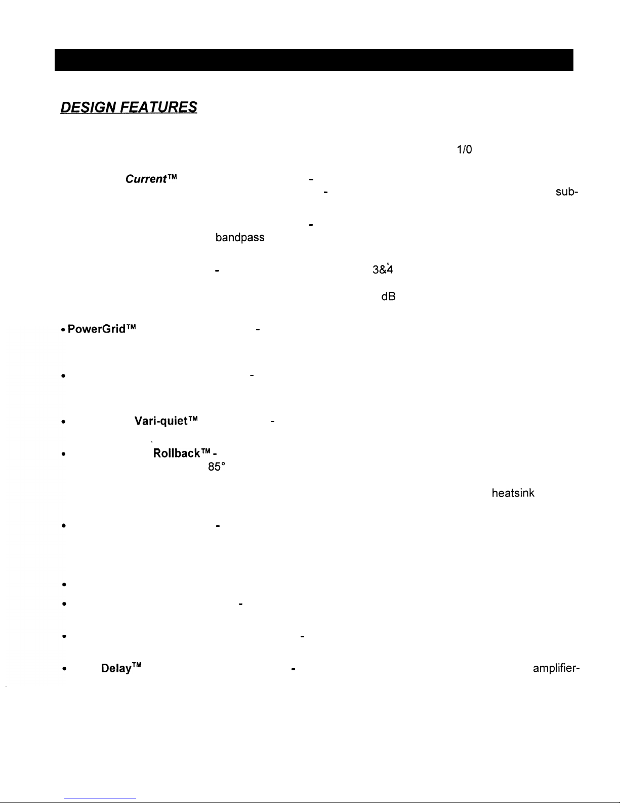
l Uncompromising Design and Construction including mil-spec glass epoxy circuit boards and high
current, custom gold-plated, solid aluminum connections that will accept up to l/O gauge power/ground
wire.
l Auto High
CurrentTM
(subwoofer channel only) - Soundstream’s exclusive circuit which automatically
optimizes your amplifier to its particular application
-
High Current, low impedance loads (multiple
sub-
woofers, less than 2 ohms) or High Power, higher impedance loads (2 ohms and up).
l Continuously Variable Electronic Crossover
-
Continuously variable 4, 3 or 2-way crossovers with
12 dB/octave high pass and bandpass filters, and a 24 dB/octave subwoofer low pass filter. The six
non-subwoofer channels of the DaVinci amplifier can be used to drive almost any conceivable system!
l Rear Channel De-emphasis
-
In 2 or 3-way mode, Channels
3&4
of the DaVinci amplifier can be used
for rear fill, and include a de-emphasis contour filter; a circuit based on theater surround technology in
which rear fill information is rolled off at 6 dB/octave with a -3 dB point at 7,000 Hz to provide a more
realistic listening experience.
PowerGrid
TM
Power Supply Design - All power supply components are located near one another, for
the shortest possible current path and are connected by thick, wide PCB traces, which ensure rapid,
high current delivery.
Ultra-Low ESR Capacitance Bank - Multiple miniature “stiffening” capacitors ensure rapid power de-
livery for dynamic peaks.
Multiple small input power capacitors are used to provide a lower ESR
(Equivalent Series Resistance), which means more power, faster.
Proprietary
Vari-quietTM
Fan Cooling
-
Internal Heat Sinking and thermostat controlled fan system
maintain safe operating temperatures.
.
Smart Thermal
RollbackTM -
Most amplifiers shut off when they get too hot.
In the unlikely event the
DaVinci amplifier reaches 85” C, it will gradually roll back its average power (without affecting the
dynamics). Once the amplifier has cooled off, it returns to full power output. If overheating should
continue, a second thermal sensing protection circuit will shut off the amplifier if the heatsink reaches
95” c.
Unregulated Power Supply - 4 ohm power ratings are measured at 12 volts, which means substantially greater output in the real world when the vehicle is running, where voltages range from 13.6 to
14.4 volts.
Dynamic capability of the unregulated power supply is vastly greater than that of a tightly
regulated power supply.
Fault Monitor LED on the front panel notifies you of a blown power supply fuse.
1 Ohm Subwoofer Drive Ability - The DaVinci subwoofer channel is designed to be stable into any
impedance, down to 1 ohm.
Seven Dual Discrete Class A Drive Stages - Over six times the drive current of most amps, which
maximizes linearity into any load.
Drive
DelayTM
Muted Turn-on/off Circuit - A unique circuit which completely eliminates amplifier-
related turn-on/off noises.
.
Fully-Balanced Studio Quality Class A Inputs with the Limited Edition
BLT4TM 4Channel
Balanced
Line Driver (included) for professional quality performance and noise cancellation. The
6-pin
DIN plug
carries (+) and
(-)
signal information for left and right channels, audio ground, and
*I5
Vdc to operate
the Soundstream
BLT4TM
Balanced Line Transmitter.
Flexible Input Sensitivity - Variable input sensitivity controls for use with a balanced line transmitter,
such as the Soundstream BLT4.
LSE.Q - Fully adjustable subwoofer equalization circuit providing frequency and level
“Q”
adjustment
for optimum subwoofer performance. A frequency tracking subsonic filter protects woofers from potentially harmful low frequency information and maximizes output in a usablerange.
A/RBASSTM
Upgradable - This feature allows wireless remote control level adjustment of the
sub-
woofer channel of the
DaVinci amblifier.
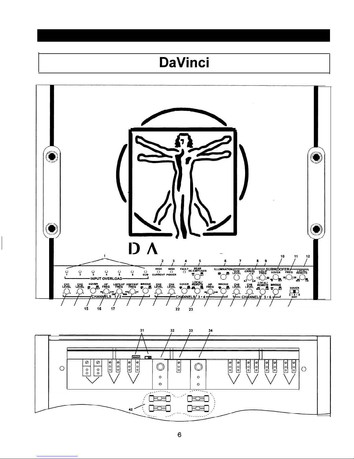
DaVinci
DA
VINCI
l-3
l-4 I-5
l-6 l-7
l-8 l-9
2-O
2-l
2.2
25
24 25 26
27
28 29
30
FRONT PANEL
35
36 37
0
0
v v v v
38 39
40
41
,
I
I
I I
.
__-----__
_..----_
I-
-s
_-
.
.
BOTTOM PANEL
6
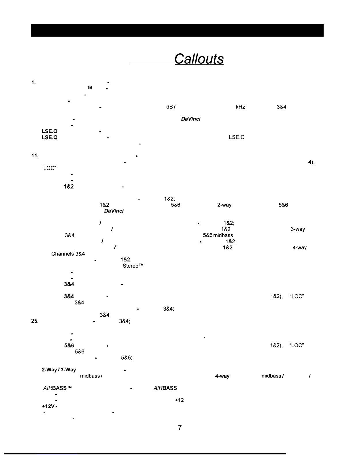
Key to
Calloutq
1.
2.
3.
4.
5.
6.
7.
8.
9.
10.
Input Overload Indicators - Indicates the signal input level or input gain level is too high (Channels 1 through 7).
Auto High CurrentTMLED - Indicates amplified subwoofer channel power on in “High Current” mode.
High Power LED - Indicates amplified subwoofer channel power on in “High Power” mode.
Fault LED - Indicates a blow power supply fuse.
Rear Fill De-Emphasis - Select “IN” to engage the 6 dB / octave low pass filter at 7
kHz
on Channels
3&4
(2 or 3 way
modes only).
Illumination - Turns on and off the back lighting behind the
DaVinci
icon (Vitruvian Man).
Input Level - Subwoofer channel level control.
LSE.Q
Gain(Q) Control - Adjustment for the filter Q (Boost) for the LSE.Q sub-sonic protection circuit.
LSE.Q
Frequency Control - Adjustment for the high pass filter frequency for the
LSEQ
sub-sonic protection circuit.
Subwoofer Channel Crossover Switch - Select “IN” for use with the internal crossover, or “OUT” for use with an
external crossover.
II.
12.
13.
14.
15.
16.
17.
18.
19.
20.
21.
22.
23.
24.
25,
26.
27.
28.
29.
30.
Low Pass Crossover Adjustment Pot - Subwoofer channel; crossover frequency setting for the internal low pass filter.
Subwoofer Channel Input Select - Select “REM” for inputs from remote inputs (internal link to Channels 1 through
4),
or
“LOC” for the local subwoofer channel input.
Input Level -Channel 1 independent level control.
Input Level - Channel 2 independent level control.
Channel
l&2
Crossover Switch
-
Select “IN” for use with the internal high pass filter, or “OUT” for use with an external
crossover or full range operation.
High Pass Crossover Adjustment Pot - Channels
l&2;
crossover frequency setting for the internal high pass filter. This
filter applies to Channels
l&2
in 2-way mode, Channels
5&6
remote input in 2-way mode, or Channels
5&6
high pass in 3
and 4-way mode. (See the DaVinci flow chart diagram and system diagrams on pages 17 and 18 for a more detailed
explanation.)
Low Range Band Pass / High Pass Crossover Adjustment Pot - Channels
l&2;
crossover frequency setting for the
internal low range band pass / high pass filter. This filter applies to Channels
l&2
satellite high pass filter in 3-way mode,
Channels
3&4
midrange high pass filter in 4-way mode, and Channels
5&6
midbass low pass filter in 3 and 4-way modes.
High Range Band Pass I High Pass Crossover Adjustment Pot - Channels
l&2;
crossover frequency setting for the
internal high range band pass / high pass filter. This filter applies to Channels
l&2
tweeter high pass filter in 4-way mode
and Channels’3&4 midrange low pass filter in 4-way mode.
Bridge Mono Switch - Channels
l&Z;
Select “IN” for bridged mono operation (right channel balanced input is only
used.). Select “OUT” for Coherent
StereoTM
operation,
Input Level
-
Channel 3 independent level control.
Input Level - Channel 4 independent level control.
Channel 3&4 Crossover Switch - Select “IN” for use with the internal high pass filter, or “OUT” for use with an external
crossover or full range operation.
Channel
3&4
Input Select
-
Select “REM” for inputs from remote inputs (internal link to Channels
l&2),
or
“LOC”
for the
local Channel
3&4
input.
High Pass Crossover Adjustment Pot - Channels
3&4;
crossover frequency setting for the internal high pass filter. This
filter applies to Channels
3&4
only in 2 and 3-way modes.
Bridge Mono Switch - Channels
3&4;
Select “IN” for bridged mono operation (right channel balanced input is only
used.). Select “OUT” for Coherent Stereo operation.
Input Level
-
Channel 5 independent level control.
Input Level - Channel 6 independent level control.
.
Channel
5&6
Input Select - Select “REM” for inputs from remote inputs (internal link to Channels
l&2),
or “LOC” for the
local Channel
5&6
input.
Bridge Mono Switch - Channels
5&6;
Select “IN” for bridged mono operation (right channel balanced input is only
used.). Select “OUT” for Coherent Stereo operation.
2-Way
/
3-Way
Crossover Switch - All Channel operation. Select 2-way for standard subwoofer satellite operation.
select 3-way for midbass / satellite operation on the front channels. Select 4-way operation for midbass / midrange
/
tweeter operation on the front channels.
31.
A/RBASSTM
Connector and Switch - Optional AIRBASS subwoofer level control connector and input switch.
32.
GND - Main ground connection. Bolt to a clean chassis ground in the vehicle.
33.
REM - Remote turn-on input from the head unit. Accepts
+I2
V.
34.
+12V - Connected to a fuse or circuit breaker, then to the battery’s positive post.
35.- 41. Speaker Connections - Channels l-6 and subwoofer speaker connections.
42.
Main Fuses - Main power supply fuses.
7
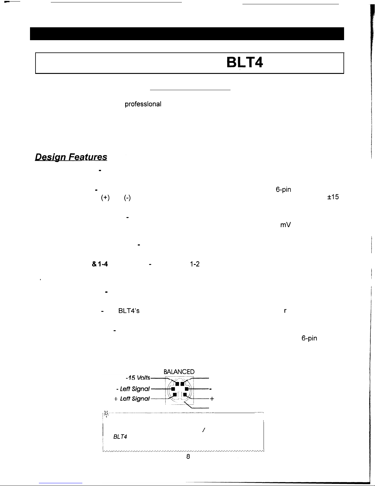
Limited Edition
BLT4
BALANCED INPUT
The DaVinci amplifier utilizes professlonal quality true balanced line audio inputs for maximum fide
and noise cancellation. Supplied with the DaVinci is a Limited Edition BLT4 Balanced Line
Transmitter, finished in the same 24 karat gold as the DaVinci. The BLT4 converts an unbalanced
II
ity
signal (standard RCA output from a head unit) to a True Balanced Audio signal, with all its features
and benefits.
l Phantom Power
-
The BLT4 is powered by the DaVinci amplifier via the mini-DIN cable.
eliminates additional power, ground and remote wire connections.
l Mini-DIN Cable
-
The balanced line audio cable features a small convenient
6-pin
mini-D
I
This cable carries
(+)
and
(-)
signal information for Left and Right channels, audio ground
Vdc to operate the Soundstream BLT4.
This
N plug.
and
*I5
l Flexible Input Sensitivity
-
The BLT4 is designed for optimum performance with a 5 volt balanced
signal level. Any head unit having an unbalanced signal output level from 250 mV to 5.0 V can be
used to obtain the 5 Volt balanced signal.
l Independent Level Controls
-
The BLT4 features independent Left and Right channel input level
controls for added adjustment flexibility and convenience.
l Channels l-2
& l-4
Input Select - Select input
I-2
if you have a single pair of unbalanced inputs.
Select input l-4 if you have two pairs of unbalanced inputs. This enables you to receive 4 channels
t
of balanced line output at all times.
l Clipping Indicator
-
The BLT4 also features an input level clipping LED. This I
you have reached the desired 5 Volts balanced audio signal level.
l Compact Design
-
The
BLT4’s
chassis is small enough to fit in the dash of you
radio or in-dash EQ.
ets you know when
r
car behind your
l industry Compatible
-
While there is as yet no “industry standard” for car audio balanced line
audio connections, you will find an ever-growing number of companies use the same 6-pin
connector and pin configuration (See the diagram below).
(For setting the BLT4, see the section on “Level Setting” on page 16.)
BAIANCED
+ 15
Volts
-
Right Signal
+
Right Signal
Shield
-~.-______-____-
--1
NOTE: The pin configuration shown in the diagram is the
’
view looking into the balanced input / output jacks on the
BLT4
and the DaVinci.
 Loading...