

Page 1

a
l
l
l
l
l
Page 2
CONGRATULATIONS!
You now own the REFERENCE Amplifier, the product of an
uncompromising design and engineering philosophy. Your
REFERENCE amplifier will outperform any other amplifier in the world.
To madmize the
of your system, we recommend that you
thoroughly acquaint yourself with its capabilities and features. Please retain
this manual and your sales and installation receipts for future reference.
Soundstream amplifiers are the result
highest quality control standards, and when
American craftsmanship and
installed
provide
you with many years of listening pleasure. Should your amplifier ever need
service or replacement due to theft, please record the following information,
which will help protect
your
investment.
and Serial #
Dealer’s Name
Date of Purchase
Installation Shop
Darlington Power Array
output section incorporates multiple
for faster, stronger power delivery. The transistors
between the circuit board and
“overbuilding” of
transislors instead of a few
sandwiched
in a design called
to ensure cool. efficient amplifier operation.
power supply components are
located near one another. connected by thick. wide PCB traces. which
ensures rapid, high current delivery. The entire power supply is isolated on
one side of the
board while the audio
is located opposite if,
guaranteeing minimal noise
Ultra-Low ESR Capacitance Bank-Multiple small input power capacitors
are
means more power
In the unlikely event the
to provide a lower ESR (Equivalent Series Resistance), which
Thermal
in and
Rollback
faster.
Most amplifiers
off when they get too hot.
amplifier reaches 85”
it will
gradually roil back its average power (without affecting the dynamics).
Once the amplifier has cooled off, it returns to full power
If
overheating should continue, a second thermal sensing protection circuit
will shut off the amplifier if the
reaches 95” C.
Unregulated Power Supply 4 ohm power ratings are measured at 12
volts, meaning substantially greater oulpui in the real world when the
vehicle is funning, where voltages range from 13.2 to 14.4 volts.
l
Monitor LED
on
top panel notifies you of blown power supply
l
DESIGN FEATURES
. Uncompromising Design and Construction
epoxy circuit boards and high
custom gold-plated solid brass
connections that will accept up to 4 gauge power/ground wire.
. Hlgh PowerRligh Current CapabIlity
Soundstream’s exclusive circuit
which permits customization of your amplifier to its particular
application-high current, low impedance loads (multiple subwoofers, less
than 2 ohms mono) or High Paver, higher impedance loads (2 ohms mono
and up).
. Coherent
Mono
selection for either “pure” stereo
operation or mixed mono for simultaneous stereo and mono.
2
including
glass
l
ohm Drlve
virtually any load-all the way down to
l Dual Discrete Class A Drive Stages
most amps, which maintains
l Drive
completely eliminates any amplifier-related
l Flexible hput Sensitivity
-The REFERENCE amplifiers are designed to drive
ohm stereo (1 ohm mono).
Over six times the drive current of
into low impedance loads.
Turn-oWofl
A unique circuit which
noises.
accepts voltages from 200
maximum output from the amplifier with virtually any source.
l Differential Balanced input Design
for
added
immunity to noise caused
component and vehicle electrical system interaction when using
RCA inputs.
3
to 5.0 V,
Page 3
l
123
l
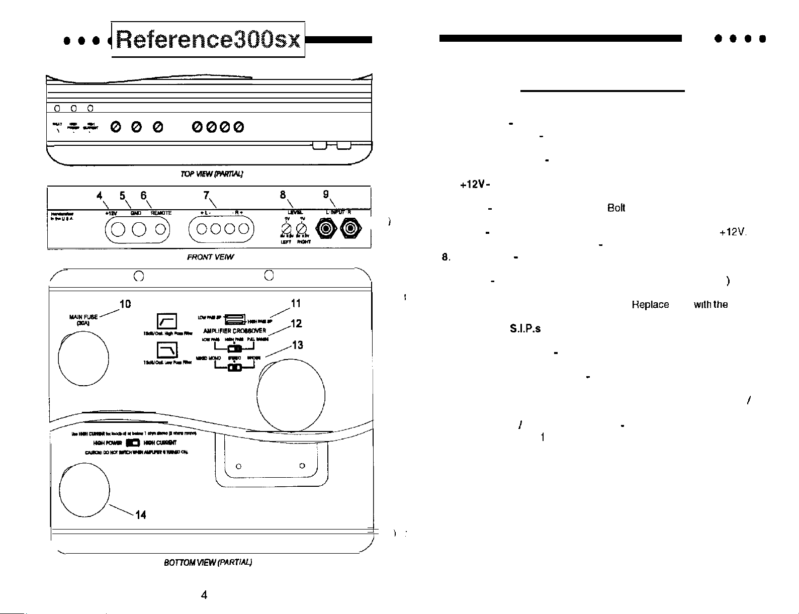
Kev to Caiiouts
Fault LED
1.
High Power LED
2.
mode.
High Current LED
3.
mode.
4.
positive post.
GND
5.
the vehicle.
6.
REM
7.
Speaker Output Connections
Input Level
controls.
Inputs
9.
only right channel input is used in “Mono” mode.
IO. Main Fuse-Main power supply fuse.
value fuse.
11. Crossover
See page 9 for more details.
12. Amplifier Crossover
amplifier operation.
13. Mixed Mono/Stereo/Bridge
operation (use right channel input). Select “Stereo” for coherent
stereo operation. Select “Mixed Mono’ for simultaneous stereo
bridged mono operation.
14. High Power
loads at or below
NOT SWITCH WHEN AMPLIFIER IS TURNED ON.
Indicates a blown fuse.
Indicates amplifier power on in “High Power’
Indicates amplifier power on in “High Current”
Connect to a fuse or circuit breaker, then to the batfery’s
Main ground connection.
Remote turn-on input from the head unit. Accepts
independent Left and Right channel input level
Right and left channel RCA (Differential Balanced
-Crossover frequency settings for the amplifier.
Select high pass, low pass or full range
Select “Bridge” for bridged mono
High Current Switch
ohm stereo (2 ohms mono).
to a clean chassis ground in
Left and right channels.
only
Use HIGH CURRENT for
CAUTION: DO
inputs;
the same
0
0
5
Page 4

l
l
REFERENCE POWER SUPPLY DESIGN
The REFERENCE amplifiers employ an extremely efficient unregulated
width modulated oower
are rated at 12
voltage available when the vehicle is running. The two major advantages of the
unregulated power supply are:
l awesome dynamic power capabilities
l added continuous power with higher voltages (see chart below)
Because of the dynamic properties of most music, all audiocomponents should
be able to react accordingly. Thanks to their unregulated power supplies, the
REFERENCE amplifiers can comfortably exceed their rated power for dynamic
portions of the music.
but
REFERENCE amolifiers from Soundstream
to take advantage of the additional
PASSIVE AND ELECTRONIC CROSSOVERS
Your REFERENCE amplifier is unique in its ability to switch between Coherent
Bridged Mono, and Mixed Mono output mode. The REFERENCE
the Mixed Mono conliguration. However,
output, and best sound quality, we recommend that you
crossover and multiple channels of amplilication.
If a single REFERENCE amplifier is to drive a
passive high and low pass crossovers will be necessary. Use the charts on
pages 7 and
to determine the values of the crossover components.
lowest distortion, maximum
an electronic
and satellite system,
6
VE
PASSIVE CROSSOVER CHART
I
6
KEY
L = high quality (DCR
C = non-polarized 50
L
4.1 mH
3.1
2.4
0.41 mH
0.31 mH
1 ohm) inductor/coil
(or greater) capacitor
4 ohms
L
8.2
3.3
2.4 mH
0.62
0.51
0.33
C
300
150
50
33 pF
L
12
6.8
4.7
3.3
0.33
C
150
75 PF
50 VF
33 VF
20
5
6
7
Page 5

l
12 dB/octave
KEY
Cl
80
130 Hz
260
Hz
Hz
Hz
Hz
12 dB/OCTAVE
PASSIVE CROSSOVER CHART
pass
=
high quality (DCR
non-polarized 50
2 ohms
Cl
5.5
4.7 mH
3.3
2.2
1.6 mH
0.76
0.5
0.47 mH
0.33 mH
0.27
560
400 pF
44 pF
30
4.7
3.6
2.2
0.9
0.75
0.22
12 dB/octave
1 ohm) inductor/coil
(or greater) capacitor
4 ohms
8 ohms
Cl
270 pF
47
27
22
6.6
4.7
3.0
1.6
1.5
3.47 mH
Cl
75
50
33
26 pF
CROSSOVER ADJUSTMENTS
In
Because of their interior dimensions, most cars will resonate or ring at these
information in this region, the fin?. response is
sounding.
car audio installations, there is a tendency for a “midbass boom.”
smooth and natural
The
electronic crossover.
The high and low pass portions of the
crossover can be set independent of
one another.
Below is a chart of S.I.P. values which
can be used for changing the factory
preset
FREQUENCY RESISTOR VALUE
Hz
73 Hz
Hz
Hz
286 Hz
465 Hz
Hz
NOTE: The following formula may be used to determine values in creating
resistor value, or 1.600.000 ohms
use 4 identically valued resistors of 2% or tighter tolerance.
drawing
of
P.
30 K
5.6
3.3 K
2.0 K
information.
COLOR CODE
Green-Green
Green-White
Violet-White
X
incorporates
points for the
divided by the
To make a custom
See
Page 6

SETTING THE
HIGH PO
The High Power/High Current switch allows the REFERENCE amplifier to be
one
two types of amps: either producing maximum power at higher
impedances (perfect for satellites)
subwoofers). The circuit operates by selecting a sat of power supply voltage
rails best suited to your particular application.
optimized for high impedance applications while the other is lower voltage
designed to provide more current. Unlike other amplifiers, Soundstream’s
REFERENCE ampllfiers can be configured to
make maximum power!
CURRENTS
at lower impedances (usually with mukiple
One is a higher voltage “tap”
any impedance and
MIXED-MONO /BRIDGED MONO
The REFERENCE amplifiers have the ability to operate in any one of the
following modes:
Coherent
maximum fidelity. Best choice for satellite speakers. Use this mode unless
Mixed-Mono is necessary.
Mixed-Mono in order to drive stereo and
for center channels. It can be used anytime you
channel. Somewhat sacrifices sonic accuracy as additional circuitry is
introduced to one channel. In
below
on the bottom of the
Bridged MOnO for dedicated single channel operation; ideal far driving
subwoofers. It is also used when large amounts of power are necessary for
single speakers. In
bridged
with identical
the
and right stereo channels for
simultaneously: works well
a summed mono
the
channel Is
channel Input
see
Hlgh Power
Hlgh Current
Watts
50x2 100x2
(100x1) (200x1) (300
25x2
(50x1) (100x1) (150x1)
50x2 100x2
150x2
1)
150x2
OTHER COMMENTS:
you blow fuses with the REFERENCE amplifiers, switch to the High Currant
mode. If the problem persists.
short, either in the speaker wire or in the speaker itself. RecWy the
before
is likafy that the amplifier is seeing a dead
COHERENT
bridged mono, on/y the right channel input is active.
NOTE:
REFERENCE amp in Mono but have stereo
outputs fmm your cmssover or source
you can put the
follow lhs normal wiring for Bridged Mono.
to drive a
in Mixed-Mono buf
11
MONO
Page 7

l
WIRING
POWER AND GROUND
To ensure maximum output from your REFERENCE amplifier, use high quality,
low-loss power and ground cables. The REFERENCE amplifiers will accept up
to 4 gauge or
below the minimum gauge power and ground wire application.
CIRCUIT
EXTERNAL
Like all audio components, the REFERENCE amplifiers must be fused near the
battery A fuse or circuit breaker must be located within
will prevent a fire in the event of a shorted cable. See the chart below
determine the
INTERNAL
The REFERENCE amplifiers are fused with automotive-type fuses.
of blown power supply fuses, the “Fault” indicator an the top panel will light.
The fuses are accessible via a plastic plug on the bottom of the amplifier. See
the chart below to determine the fuse value. Never replace the luaes with a
and
gauge power and ground cables. Determine from the chart
up
BREAKERS/FUSES
of the battery This
fuse value.
This may resufl In
the
warranty!
In the event
damage
REMOTE
Connect
is received, the amplifier will turn on.
the “Remote” to the turn-on lead
the source unit When
SIGNAL CABLE
Use a
high-quality cable that
to guarantee optimum
SPEAKER
The REFERENCE amplifiers will accept up to
high quality, flexible, multi-strand cable for best
Soundstream Speaker120 & 160 (12 and 16 gauge) are ideal.
CABLE
be easy
Soundstream’s DL.l and
install and
has
gauge speaker cable. Use a
minimal signal loss
are ideal.
and longevity.
DIAGRAM
REFERENCE Amplifier Fuse
Amplifier
30 amp automotive
Fuse
12
Battery
amp
Fuse
Page 8

l
INSTALLATION AND MOUNTING
1. AMPLIFIER LOCATION
The REFERENCE amplifiers employ highly efficient circuitry and a unique
cooling may be required if the amplifier is located in a tightly confined area
or when driving especially low impedance loads at extremely high levels.
When mounting the amplifier, it should be securely mounted to either a
panel in the vehicle or an amp board or
vehicle. The mounting location should be either in the passenger
compartment or in the trunk
moving objects. and major electrical components. To provide adequate
ventilation, mount the amplifier so that there are at least two inches of freely
circulating air above and to the sides of it.
the vehicle, away from moisture, stray or
2. SIMTCHES
Set High Power/High Current and Coherent
Mono switches to the appropriate positions (see page 11).
3. MOUNTING THE AMPLiFlER
a. Using the amplifier as a template, mark the mounting surface.
b. Remove the amplifier and drill the holes.
c. Mount the amplifier to the surface using the provided hardware.
4.
a. Run
amplifier from the source unit
b. Carefully run the positive cable from the amplifier to a fuse or circuit
breaker within 19” of the battery.
Connect the fuse or circuit breaker to the battery. Leave the circuit
breaker off or the fuse out until
d. Secure the ground cable to a solid chassis ground on the vehicle.
be necessaty to sand paint down to raw metal for a good connection.
Double check each and every connection!
f. Reconnect the fuse or circuit breaker.
5.
Power up the system and look at the green and red
configuration, one should be lit. There may be a 2 3
time the the source unit is turned on to the time that the LED
turns on. which is normal. Once the amplifier power LED is on and the
source unit is playing, you should have sound coming from the speakers.
and connect the audio signal and remote turn-on cables to the
UP
is securely mounted to the
is bolted down.
depending
the amp
It may
the
the
LEVEL SETTING
The input levels are adjusted by means of the input level controls located on the
front of the amplifier. This is a unique dual-stage circuit that adjusts both level
and gain. This topology maintains better Signal to Noise ratios even when
using sources with minimal output. In the ideal situation, all components in the
audio system reach maximum undistotted output al the same time. The reason
is because an amplifier will only make what comes inlo it bigger. So. if you
send it a distorted signal from the head unit, the amplifier is going to amplify
distorted information. The same thing holds true if an outboard processor or
crossover begins to distort before you have maximum output from the amplifier.
By setting all components to reach clipping at the same time, you can maximize
the output of your system.
procedure for the quickest, easiest means of setting the levels.
Turn the amp’s input levels to minimum position (fully counter-clockwise).
2. Set source unit volume to approximately
3. While playing dynamic source material, slowly increase the amplifier’s
input level until a near maximum undistorted level is heard in the system.
For the REFERENCE amplifiers, follow the below
of full volume.
CAUTION!
Prolonged listening af high lavels may
new Soundstream REFERENCE amplifier sounds better than
ever heard, exercise caulion ropravenr hearing damage.
in hearing loss.
Even
you’ve
PROTECTION ClRCUlTRY
REFERENCE amplifier is protected against both overheating and short
circuits by means of the following circuits:
l Main power supply luses
Circuit breakers
l Smart Power Supply Thermal Rollback activating at 85°C.
l A fail-safe thermal protection circuit activating at 95°C.
Your amplifier also incorporates an innovative Fault Diagnosis system that
identifies a blown power supply fuse.
NOTE: If you experience blown main power supply fuses.
values beyond the original fuse value! Doing so
may damage your
amplifier.
void your warranty and
NOT increase
NOTE:
to
There may be a sizable spark when connecting Ihe
amplifier for
lime. This is caused by currenl rushing info the amplifier
14
ground lead
15
Page 9

l
ACCESSORY
l
Soundstream’s new
amplifier. This feature allows wireless RF remote control
level adjustment of the amplifier, while the low pass filler on the amplifier’s
internal crossover is engaged.
NOTE: The
accessory is added to a
configures
Mono/Bridged Mono switch is bypassed.) Therefore, when
follow the Eridaed Mono
Installing
adding the
labeled on the amplifier’s main circuit board. DO NOT set the
switch to the ‘IN’
NOT move the
damage your speakers.
manual for more details.)
the
accessory is intended lo be used only
amplifier is driving subwoofers. When the
into
Bridged Mono
and
involves removing the bottom plate of the amplifier,
circuit board, and flipping a switch. The switch is
unlessthe
switch while the amplifier is ‘ON’. Doing so
(Please refer to the
feature can be added to the
the
ampkfier,
mode.
(The Coherent
instructions. 17.)
module has been added. DO
owner’s
installation
TROUBLESHOOTING
PROBLEM
No sound and
No sound and
is not installed
Fault LED is lit. Amp has power, but l amp power supply fuse is blown or
the Power LED is not lit
are not lit
are lit, and
I
l no power or ground at amp
l no remote
l blown fuse near battery
.
missing
CAUSE
signal
switch is engaged
High Power
High Current
watts
THD
Signal to Noise
Frequency Response
Stereo Separation
Damping
Input Sensitivity
Input Impedance
50x2
25 x2 50X2
(50
1)
100x2
%
ohms
Crossover Specifications
High Pass: 12 dB/octave, factory
Low Pass: 12 dB/octave, factory set at 75 Hz
at 150 Hz
Dimensions (W x D x
8.625”
9.8”
2.25”
150x2
(300
100x2
1)
150x2
Repeatedly blown amp fuse,
activation of Smart Power
Circuit
. check speaker configuration, amp
be in “High Power” mode, put
amp into “High Current” mode if
speaker load is less than 2 ohms
(see
current
l speaker or leads
. verify adequate
16
“Setting High Power/High
be shorted
ventilation
SERVICE
Your Soundstream REFERENCE amplifier is protected by a limited warranty.
Please read the enclosed warranty card.
Page 10

 Loading...