

SoundScope A12, SoundScope A8 Owner's Manual
OWNER’S MANUAL >>
Multi-Channel, Class D,
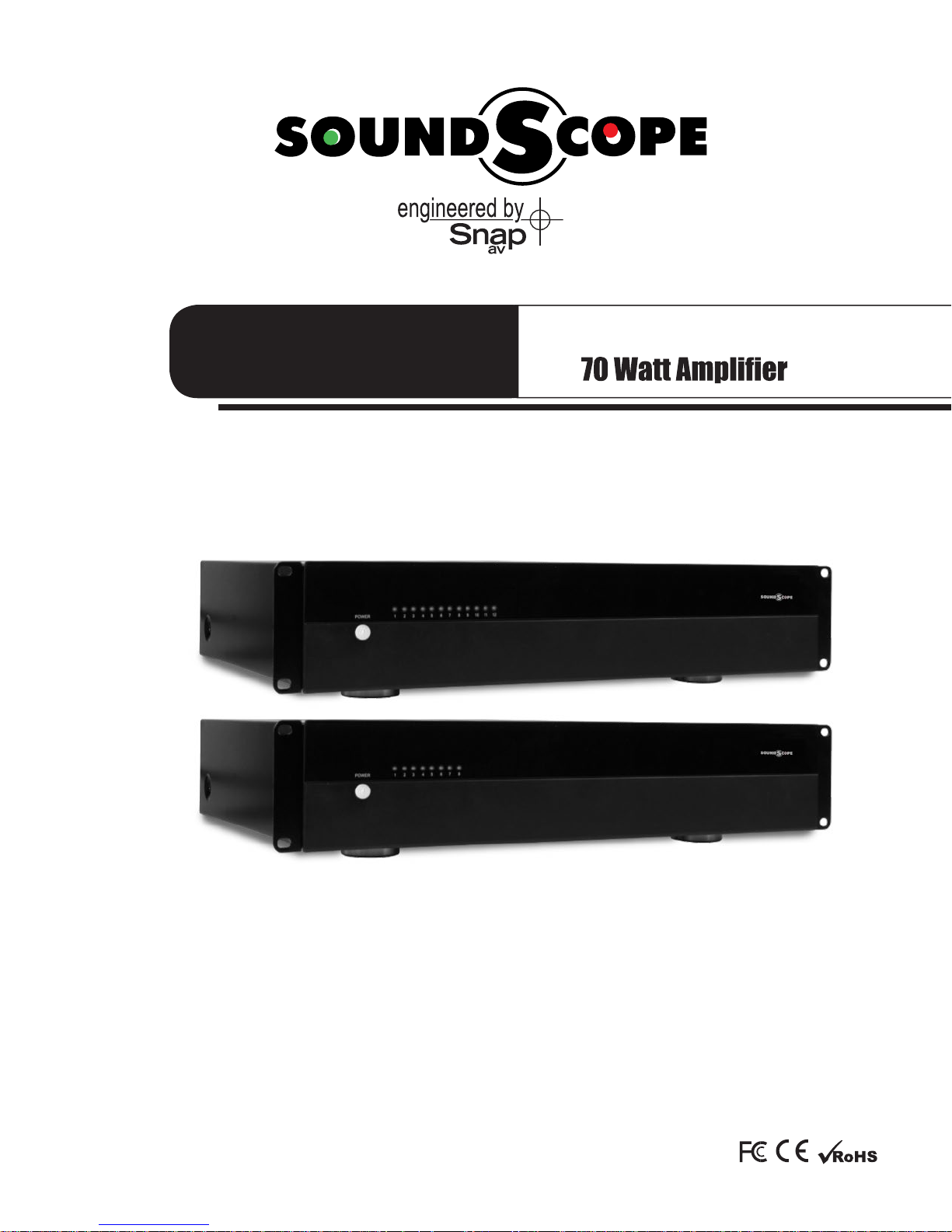
SoundScope A12
12 CHANNEL
SoundScope A8
8 CHANNEL

SoundScope A8&A12 Installation and Users Manual
IMPORTANT SAFETY INSTRUCTIONS
WARNING:
1. Read the following instructions carefully.
2. Keep manual for future reference.
3. Heed all warnings.
4. Follow all instructions in this manual.
5. Do not use this apparatus near water.
6. Clean only with a dry cloth.
7. Do not block any ventilation openings. Install according to manufacturer’s instructions.
8. Do not install near any heat sources such as radiators, heat registers, stoves or other apparatus
9. Do not override the safety purpose of the polarized or grounding-type plug. A polarized plug has two blades -
one wider than the other. A grounding type plug has two blades and a third grounding prong. The wide blade
electrician for replacement of the obsolete outlet.
10. Protect the power cord from being walked on or pinched particularly at plug, convenience receptacles, and
the point where it exits from the apparatus.
,
or sold with the apparatus. When a cart is used, use caution when moving the
cart/apparatus combination to avoid injury from tip-over.
13. Unplug this apparatus during lightning storms or when unused for long periods of time.
in any way, such as when the power-supply cord or plug is damaged, liquid has been spilled or objects have fallen
into the apparatus, the apparatus has been exposed to rain or moisture, does not operate normally, or has
been dropped.
15. To completely disconnect this equipment from the AC mains, disconnect the power supply cord plug from
the AC receptacle.
CAUTION
CAUTION: TO REDUCE THE RISK
OF ELECTRICAL SHOCK, DO
NOT REMOVE COVER. NO USER
SERVICEABLE PARTS INSIDE.
REFER SERVICING TO QUALIFIED
SERVICE PERSONNEL.
triangle, is intended to alert the user to the presence of
uninsulated dangerous voltage within the product’s enclosure
shock to persons.
The exclamation point within an equilateral triangle is intended
to alert the user to the presence of important operating
and maintenance (servicing) instructions in the literature
accompanying the appliance.
pg.3
SoundScope A8&A12 Installation and Users Manual
FEATURES
DURABLE AUDIOPHILE DESIGN
analog designs.
MULTIPLE STAGES OF PROTECTION
Each pair of channels (or Zone) is individually protected with an operation mode indicated by bi-color LEDs on the front of the
to a short, only the channels that are affected will be turned off. The other zones will continue to play.
GLOBAL A & B AND DIRECT INPUTS
A dedicated input can be assigned to a pair of channels via the channel Line In connection. Each pair of channels can also
receive the right channel, and the even-numbered channels will receive the left channel. This is further indicated by the color of
the channel Line In jacks (odd numbers have white jacks and even numbers have red jacks). A 3 position switch is available for
each channel pair to choose between the line-in and the 2 Global-Inputs.
today’s demanding custom audio installations.
INDIVIDUAL CHANNEL AND GAIN ADJUSTMENTS
Each pair of channels has its own level adjustment which adjusts the maximum output. This allows the output of to be perfectly
matched to its area. It can also serve to provide a limit on how loud each speaker may be allowed to play. Be sure set the
volume at a level that does not clip or cause distortion when the volume is at the maximum level. This can cause damage to the
INSTALLATION-FRIENDLY CONNECTIONS
Each pair of speakers feature a removable speaker wire connector that accommodates up to 14 gauge stranded speaker wire.
The power cord is removable as well, facilitating fast and simple installations. The Global Inputs, Loop Output, and individual
Channel Inputs are all high-quality RCA connectors.
BRIDGING
The power output of adjacent channels can be combined to provide extra power when needed in certain areas.
Maintain an 8 ohm minimum when using bridge mode.
RACK-MOUNTABLE
POWER MODE
Power state can be toggled using the front Power Button, 12V input, or Audio Sensing. The method for power toggle is set by
on the operation of each mode.
Note: The front panel power button is inoperative when the 12V Trigger or Audio Sense power modes are selected.
pg.4

SoundScope A8&A12 Installation and Users Manual
SoundScope A12
1 2 3 4 5 6 7 8 9 10 11 12
REAR PANEL FEATURES (12D and 8D)
1. GLOBAL INPUT
Easily amplify outputs from any stereo source across any/all channels
2. LOOP OUT
3. GAIN CONTROL
Allows independent gain for each pair of inputs
4. BRIDGED SWITCH
Easily couple two channels together for increased power
NOTE: 8-ohm minimum when using bridge mode
5. LINE INPUTS
Individual channel inputs for use with multi-channel preamps/ or dedicated sources
pg.5
 Loading...