

Page 1

WF-U2600
True Diversity Dual
Multi-Channel Wireless
Microphone System
USER MANUAL
Please read this manual carefully and proper take care of this manual.
Page 2

Dear customer,
®
First of all thanks far purchasing a SOUNDSATION
product. Our mission is to satisfy all
possible needs of musical instrument, professional audio and lighting users offering a
wide range of products using the latest technologies.
We hope you will be satised with this item and, if you want to collaborate, we are
looking for a feedback from you about the operation of the product and possible improvements to introduce in the next future. Go to our website www.soundsationmusic.
com and send an e-mail with your opinion, this will help us to build instruments ever
closer to customer’s real requirements.
One last thing: read this manual before using the instrument, an incorrect operation
can cause damages to you and to the unit. Take care!
The SOUNDSATION Team
Page 3

ENGLISH
1. TABLE OF CONTENTS
1. UNPACKING ...............................................................................................................6
2. ACCESSORIES .............................................................................................................6
3. OVERVIEW .................................................................................................................. 7
4. MAIN FEATURES ........................................................................................................7
5. RECEIVER CONTROL AND FUNCTIONS ...................................................................8
5.1. Receiver A & B Displays.....................................................................................................................................10
6. RECEIVER INSTALLATION .......................................................................................10
7. SYSTEM SETUP .........................................................................................................11
7.1. Channel Setup Mode ..........................................................................................................................................11
7.2. Handheld Microphone Smart Mute Setting ..............................................................................................13
7.3. Transmitter Power Setting ................................................................................................................................13
8. HAND-HELD MICROPHONE ...................................................................................13
8.1. Handheld Microphone LCD Display .............................................................................................................14
8.2. Hand-held Microphone Operation ...............................................................................................................15
9. POCKET TRANSMITTER AND HEADSET................................................................16
10. AUDIO CONNECTIONS ............................................................................................18
11. SPECIFICATIONS ......................................................................................................19
12. FREQUENCY TABLE ..................................................................................................20
13. DECLARATION OF CONFORMITY ..........................................................................21
14. WARRANTY AND SERVICE .....................................................................................22
15. WARNING.................................................................................................................22
3
Page 4

ENGLISH
IMPORTANT SAFETY SYMBOLS
The symbol is used to indicate that some hazardous live terminals are
involved within this apparatus, even under the normal operating con-
ditions, which may be sufcient to constitute the risk of electric shock
or death.
The symbol is used in the service documentation to indicate that spe-
cic component shall be replaced only by the component specied in
that documentation for safety reasons.
Protective grounding terminal
Alternating current/voltage
Hazardous live terminal
Denotes the apparatus is turned on
Denotes the apparatus is turned off
WARNING:
CAUTION:
Describes precautions that should be observed to prevent the danger
of injury or death to the operator.
Describes precautions that should be observed to prevent danger of
the apparatus.
WF-U2600 User manual
TAKING CARE OF YOUR PRODUCT
f Read these instructions
f Keep these instructions
f Heed all warning
f Follow all instructions
Water / Moisture
The apparatus should be protected from moisture and rain and can not be used near
water; for example near a bathtub, a kitchen sink, a swimming pool, etc.
Heat
The apparatus should be located away from heat sources such as radiators, stoves or
other appliances that produce heat.
4
Page 5

ENGLISH
WF-U2600 User manual
Ventilation
Do not block areas of ventilation opening. Failure to do could result in re. Always
install according to the manufacturer’s instructions.
Object and Liquid Entry
Objects do not fall into and liquids are not spilled into the inside of the apparatus for
safety.
Power Cord and Plug
Protect the power cord from being walked on or pinched particularly at plugs, convenience receptacles, and the point where they exit from the apparatus. Do not defeat
the safety purpose of the polarized or grounding-type plug. A polarized plug has two
poles; a grounding-type plug has two poles and a third grounding terminal. The third
prong is provided for your safety. If the provided plug does not t into your outlet, refer
to an electrician for replacement.
Power Supply
In case of external power supply, the apparatus should be connected to the power supply only of the type as marked on the apparatus or described in the manual. Failure to
do could result in damage to the product and possibly the user. Unplug this apparatus
during lightning storms or when unused for long periods of time.
Fuse
To prevent the risk of re and damaging the unit, please use only of the recommended fuse type as described in the manual. Before replacing the fuse, make sure the unit
turned off and disconnected from the AC outlet.
Electrical Connection
Improper electrical wiring may invalidate the product warranty.
Cleaning
Clean only with a dry cloth. Do not use any solvents such as benzene or alcohol.
Servicing
Do not implement any servicing other than those means described in the manual. Refer
all servicing to qualied service personnel only. Only use accessories/attachments or
parts recommended by the manufacturer.
Warning
Please remember the high sound pressure do not only temporarily damage your sense
of hearing, but can also cause permanent damage. Be careful to select a suitable volume.
Interference from cell phone
Using a cell phone near the wireless system can induce noise. If this occurs, move the
cell phone further away from the components of the wireless system.
5
Page 6

ENGLISH
2. UNPACKING
WF-U2600 system is composed by following parts:
WF-U2600HH
f 1x Receiver
f 1x External Power Adapter
f 2x Hand Transmitter
f 4x 1.5V AA-Type Batteries
f 2x Antennas
f 2x 19” Rack adapters
f 4x Screws
f 1x 6.5mm Jack to 6.5mm Jack audio cable
f This User Manual
WF-U2600HP
f 1x Receiver
f 1x External Power Adapter
f 1x Hand Transmitter
f 1x Pocket Transmitter
f 1x Headset Microphone
f 4x 1.5V AA-Type Batteries
f 2x Antennas
f 2x 19” Rack adapters
f 4x Screws
f 1x 6.5mm Jack to 6.5mm Jack audio cable
f This User Manual
WF-U2600 User manual
ATTENTION: Packaging bag is not a toy! Keep out of reach of children! Keep
in a safe place the original packaging material for future use.
3. ACCESSORIES
SOUNDSATION can supply a wide range of quality accessories that you can use with
your WIREFREE Series wireless microphone system, like Cables, Mixers, Speakers, Ampli-
ers, Stands, etc.
All products in our catalogue has been long tested with this device so we recommend
to use Genuine SOUNDSATION Accessories and Spare Parts. Ask your SOUNDSATION
dealer for any accessories you could need to ensure best performance of the product.
6
Page 7

ENGLISH
WF-U2600 User manual
4. OVERVIEW
WF-U2600 is a dual UHF True Diversity professional wireless microphone with 240
channels for each microphone, and a simple and intuitive user interface. “True Diversity”
means that the receiving system is equipped with two antennas, two receiving circuits
and a device capable of continuously choose the stronger and interference-free signal.
The WF-U2600 is built with leading technology that allows the integration of many
of the major functions - such as amplication section, digital signal processing, PLL
(Phase-Locked Loop) frequency synthesis, and more - into a few CHIPs. This allows us
to offer highly professional performance yet cost-effective products.
The WF-U2600 is also equipped with the automatic frequency search system and IR
sync system for channel synchronization between receiver and transmitter in a quick
way. Furthermore, the Digital Pilot Technology not only allows to monitor reception
level and battery charge, but even to operate up to 200 sets multiple systems without
problems.
Finally, the receiver comes with a kit for mounting in 1 standard 19” rack unit. The kit is
composed by two L-shape adapters and four screws to mount them on both receiver
sides. WF-U2600 systems are available in 2 congurations:
WF-U2600HH
• 2 x Hand Transmitter with Professional Dynamic Cardioid Capsule
• 1 x Dual UHF True Diversity Receiver
WF-U2600HP
• 1 x Hand Transmitter with Professional Dynamic Cardioid Capsule
• 1 x Pocket Transmitter
• 1 x Headset Microphone with Professional Condenser Cardioid Capsule
• 1 x Dual UHF True Diversity Receiver
5. MAIN FEATURES
f UHF True Diversity Technology to Avert Interferences
f 240 Preset Channels for each microphone, and IR Matching System for Quick Setup
f 630-660MHz UHF Band
f Simple and Outright User Interface with LCD display on Transmitters and TFT color
display on Receiver
f Digital Pilot Technology to allow up to 200 systems operation simultaneously with-
out interferences
f Transmitter AF-level and Battery-Low Monitoring directly on the Receiver
f Automatic mute function on microphones, which saves battery power effectively
when it is on but not using
7
Page 8

ENGLISH
WF-U2600 User manual
f 80m Ideal Distance (without obstacles)
f Professional Hand held Microphone with Dynamic Cardioid Capsule
f Body-pack with Connector Locking System (WF-U2600HP model only)
f Professional and Lightweight Headset with High-Sensibility Condenser Cardioid
Capsule (WF-U2600HP model only)
f 19” Rack-Mount adapter kit included
6. RECEIVER CONTROL AND FUNCTIONS
True Diversity multi-Channel wireless receiver
POWER
CHANNEL
MIN MAX
VOLUME
LOCK
ENTERUPDOWN IR
DOWN
IR
CHANNEL
LOCKUP
MIN MAX
VOLUME
ENTER
WF- 2600
unbalanced outputs
ANT ANT
MIX CH-A
Bal. Outs
DC INPUT
CH-B
12V-18V 1.5A
CH-ACH-B
MADE IN CHINA
1. Power Switch: It switches on and off the receiver. Please notice that function
is active at power on. Hold LOCK button for a few seconds to unlock the receiver
and access to the parameters (refer to the section "8. SYSTEM SETUP" at page 11
for details).
2. A-System TFT Color Display: It shows all functions and allows easy and intuitive
programming of all parameters.
3. A-Volume: It adjusts A-system audio output level.
4. A-LOCK: It locks/unlocks A-system in order to avoid accidental setup parameters
changes.
5. A-UP Button: During System-A editing, it increases current parameter’s value.
8
Page 9

ENGLISH
WF-U2600 User manual
6. A-Enter Button: It access to all editing functions of A-System (See section "8. SYS-
TEM SETUP" at page 11 for further details).
7. A-DOWN Button: During System-A editing, it decreases current parameter’s value.
8. A-IR Button: Press it to synchronize the operating channel between receiver and
A-transmitter.
9. IR Sensor: It is the infrared sensor used to synchronize the operating channel
between receiver and the two transmitters (both A and B Systems).
10. B-UP Button: During System-B editing, it increases current parameter’s value.
11. B-LOCK: It locks/unlocks B-system in order to avoid accidental setup parameters
changes.
12. B-IR Button: Press it to synchronize the operating channel between receiver and
B-transmitter.
13. B-DOWN Button: During System-B editing, it decreases current parameter’s value.
14. B-Enter Button: It access to all editing functions of B-System (See section "8. SYS-
TEM SETUP" at page 11 for further details).
15. B-Volume: It adjusts B-system audio output level.
16. B-System TFT Color Display: It shows all functions and allows easy and intuitive
programming of all parameters.
17. A-Antenna: It receives RF signals from transmitters. It’s important to always plug
the two supplied antennas to their connectors on rear panel, taking care to screw
them all the way, and ensure maximum receiving capacity of the system.
18. B-Antenna: Same as Antenna-A.
19. Mix Output: It is the channel-A + channel-B unbalanced audio line output with ¼”
Jack to use in case of connection to mixers or audio equipment with unbalanced
connections.
20. Unbalanced Output B: It is the System-B unbalanced audio line output with ¼”
Jack to connect to your mixer or audio system. For more details about the internal
wiring of balanced cables, refer to paragraph "11. AUDIO CONNECTIONS" at page
18.
21. Unbalanced Output A: Same as unbalanced output B but for System-A.
22. Balanced Output B: It is the Channel-B balanced XLR audio line output to connect
to your mixer or audio system. For more details about the internal wiring of balanced cables, refer to paragraph "11. AUDIO CONNECTIONS" at page 18.
9
Page 10

ENGLISH
WF-U2600 User manual
23. Balanced Output A: Same as balanced output B but for Channel-A.
24. DC Input: Connect here the external power supply (12-18Vdc – 1.5A)
6.1. Receiver A & B Displays
660.00
Soundsation WF-U2600 operates with true diversity technology. This means that the
receiver has inside two independent receiving circuits that share both antennas. Depending on the position of the two transmitters, possible obstacles and their distance
from the receiver, the WF-U2600 chooses best radio signal, always ensuring impeccable
sound quality.
This bar indicates radio signal level. The longer, the higher.
It indicates audio signal level. The longer, the higher.
When on, it indicates that all keys are locked, long press LOCK button to
unlock.
It indicates current frequency group (8th group in the example).
It indicates current frequency in the group (1st frequency in the example)
Indicates receiver is mute/unmute.
This icon shows the battery level of hand-held or pocket transmitter.
Indicates current frequency is 660.00MHz.
Free needed frequency scan function, to nd out frequency
needed upward or downward.
Indicates transmitter battery level.
7. RECEIVER INSTALLATION
Before using the system, please be sure that the receiver is correctly placed at a
distance of about 1m from oor, and 1m from walls or other big physical obstacles
(columns or other radio-frequency equipment).
10
Page 11

ENGLISH
WF-U2600 User manual
f Pull out the two antennas (17) and (18), make them to be perpendicular with the
receiver.
f Connect the supplied power adapter to the DC power supply socket (24).
f Connect balanced audio outputs A (22) and B (23) or the unbalanced/mix output (19,
20, 21) to your mixer or sound system, using the appropriate cables (see section "11.
AUDIO CONNECTIONS" at page 18 for further details).
f Turn on the receiver by pressing POWER button (1). LCD (6) will light up showing
current settings of the system.
8. SYSTEM SETUP
Please notice that when you switch the receiver on LOCK function ( ) is active on both
Channels. Hold for a few seconds SET button A (4) or SET button B (7) to unlock and
have access to parameters. The icon will change into
.
NOTE: In addition to the active LOCK function, at power on the receiver is
even muted (
align it on the same receiver’s channel.
8.1. Channel Setup Mode
icon is on in the display) until you turn on the transmitter and
Group Setting
660.00
f Long press LOCK key to unlock the system, select the GR tag by UP/DOWN key, press
enter key to conrm, then choose the group by UP/DOWN key, press enter key to
conrm, then SYNC by IR key.
11
Page 12

ENGLISH
WF-U2600 User manual
NOTE: If during Group selection you do not press any button for about 10
seconds, the system automatically returns to LOCK mode. It is therefore necessary to unlock the receiver again to re-access Group setup mode.
Channel Setting
660.00
f Long press LOCK to unlock the receiver, then press UP/DOWN to choose the chan-
nel setting function, press ENTER to conrm, press UP/DOWN again to select the
requested channel, press ENTER again to conrm, press IR button to sync.
NOTE: If during Channel selection you do not press any button for about
10 seconds, the system automatically returns to LOCK mode. It is therefore
necessary to unlock the receiver again to re-access Channel setup mode.
Frequency Auto Scan Setting
SOUNDSATION WF-U2600 is equipped with a useful automatic frequency scan function. This allows you to always choose those channels with less problems and make
setting operations extremely quick.
660.00
f Long press LOCK to unlock the receiver, then press UP/DOWN to choose the free
frequency auto scan setting function, press ENTER to conrm, press UP/DOWN to
auto scan for the suitable free frequency, press ENTER again to conrm, press IR
button to sync.
NOTE: If you do not press any buttons for about 10 seconds, the automatic
search goes off and the system returns to channel setting mode. If, after the
receiver is back to channel setting mode you do not press any button for
other 10 seconds, the system automatically returns to LOCK mode.
12
Page 13
ENGLISH
WF-U2600 User manual
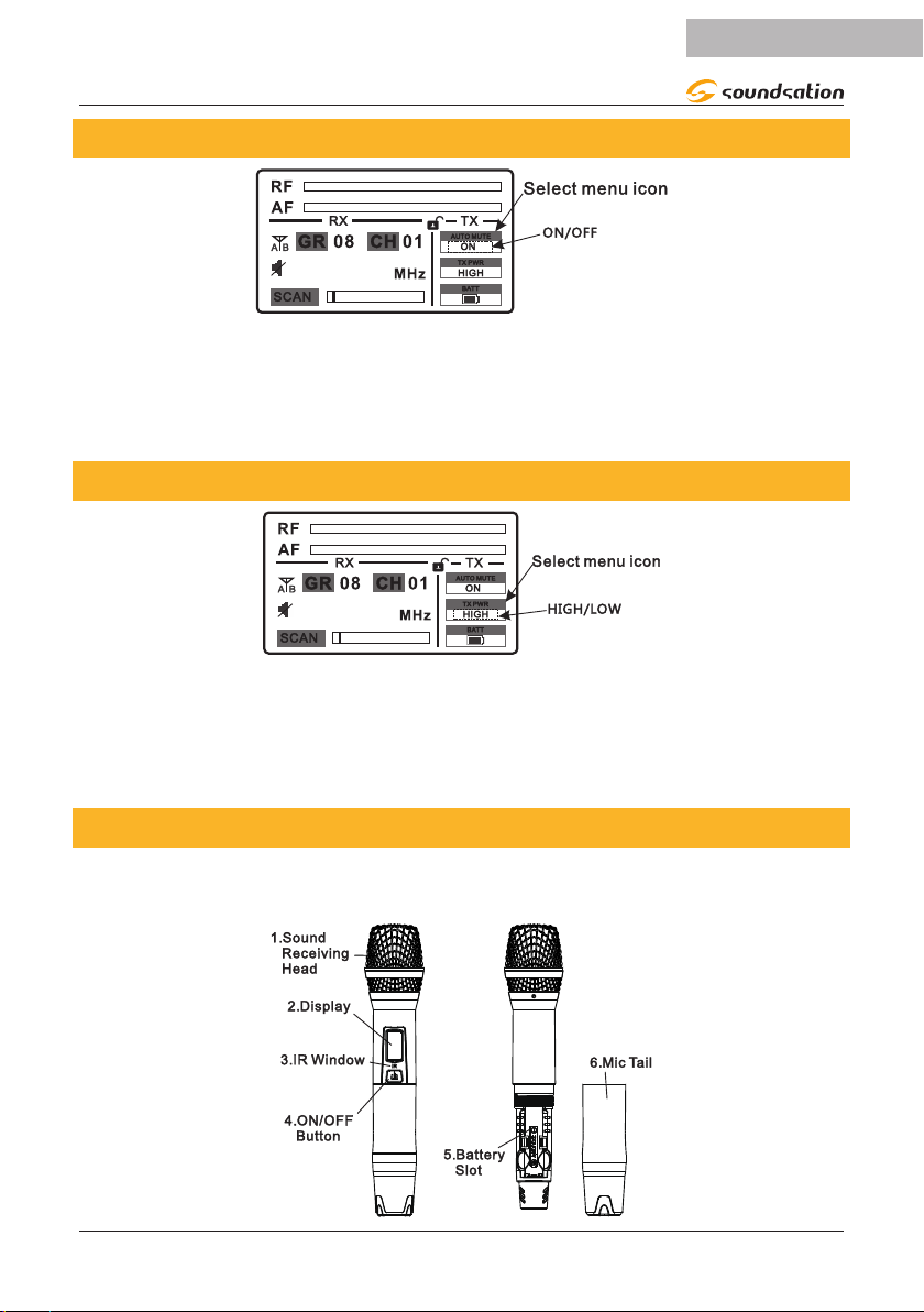
8.2. Handheld Microphone Smart Mute Setting
660.00
Long press LOCK to unlock the receiver, then press UP/DOWN to choose the Auto Mute
Setting function. Press ENTER to conrm, press UP/DOWN to select ON to turn on
smart mute function, or select OFF to turn off it. Press ENTER again to conrm; press IR
button to sync.
8.3. Transmitter Power Setting
660.00
Long press LOCK to unlock the receiver, then press UP/DOWN to choose the transmit-
ter power setting function (TX PWR). Press ENTER to conrm then press UP/DOWN
again to select HIGH power or LOW power. Press ENTER again to conrm; press IR
button to sync.
9. HAND-HELD MICROPHONE
WF-U2600HH and WF-U2600HP systems feature respectively 2 and 1 hand-held transmitters with professional dynamic cardioid capsule.
13
Page 14

ENGLISH
WF-U2600 User manual
1. Sound Receiving Head: It protects microphone capsule. Never remove it to pre-
vent damage to the internal parts of the microphone.
2. LCD Display: This back-lit display shows all important information related to set-
tings, as well as battery charge level.
NOTE: After about 5 seconds back-light is lowered, reducing battery con-
sumption. Full lighting returns each time you press Power button.
3. IR Window: During IR mode, bring this part of the transmitter close to the receiv-
er’s IR sensor to complete the operation.
4. ON/OFF button: Press and hold this button for about 2 seconds to turn on or off
the microphone.
5. Battery Slot: Insert two 1.5V AA-Type batteries, paying attention to correct polari-
ty (indicated on bottom of this battery compartment).
6. Mic Tail: Remove this cover to access the battery-compartment and insert or
replace the batteries.
9.1. Handheld Microphone LCD Display
Sync signal
GROUP Group
Channel
HI means high power, apply to long distance
LO means low power apply to room use
660.00
IR means sync signal
Indicates Group n. 8, channel n. 1
14
660.00
Battery status. When ashing means low power
When on, it indicates that smart Mute is active
Mute status, no voice. Slightly shaking can relieve it. Or a
quick press on ON/OFF button can switch between mute and
work status.
Smart mute function is opened. When falling down or no
using, will automatically mute.
Page 15

ENGLISH
WF-U2600 User manual
Long press ON/OFF button to turn off the microphone.
9.2. Hand-held Microphone Operation
f Unscrew the battery cover and insert two 1.5V AA-Type batteries. Note the polarity
of the battery.
f Long press ON/OFF button for 3 seconds. If the display doesn't light, check if batter-
ies are in correct polarity or run out of power. When battery icon is ashing means
that batteries are low of power and need to be changed.
f Hand-held microphone can only be used under same frequency with the Receiver.
f After turned on, it automatically enters default mode, and automatically saves last
frequency. It does not need to be reset without changing the settings.
WARNING: Infrared frequency response of the hand-held microphone can
only be carried out within 30 seconds after having been turned on.
Microphone Correct Handling Tips
f Don’t hold the microphone grill.
f Avoid holding the microphone on antenna position.
f Don’t hold two microphones together
15
Page 16

ENGLISH
WF-U2600 User manual
ATTENTION: Operating distance between microphone grill and mouth must
be less than 15cm
f Avoid direct the microphone toward a speaker to avoid Larsen effect, which could
damage your audio system.
10. POCKET TRANSMITTER AND HEADSET
1. Microphone: WF-U2600HP system features a headset microphone with profes-
sional condenser dynamic capsule.
2. Microphone Input: Plug here the headset audio connector. Please notice that this
connector is equipped with security threads, to prevent it from coming off during
use.
3. Volume: Adjust the audio input level of the transmitter. Use this knob to adapt
microphone signal level in order to prevent distorted sound.
4. POWER Selector: This selector has 3 positions. When it’s all to the OFF position,
the microphone is turned off; when it is in the central position, the microphone
is active but the audio is disabled; nally, when it’s all to ON position, the micro-
16
Page 17

ENGLISH
WF-U2600 User manual
phone is working and the audio is active.
NOTE: Standby central position allows the unit to transmit without audio.
This option is important to prevent interference in the receiver due to the
absence of a radio transmitting signal. It is, therefore, suggested to ALWAYS
use this standby position when you temporarily don’t sing or play but the
wireless microphone is connected to an audio system (e.g. during a pause in
a show). You can move the switch to OFF position (all down) only when you
are sure that the sound system volume is low.
5. Power LED: It lights up when the transmitter is on.
6. Antenna: It transmits the radio signal. Be careful not to bend or break this termi-
nal.
7. LCD Display: The back-lit display shows all important information relating to set-
tings, as well as battery charge level.
NOTE: After about 5 seconds back-light is lowered, reducing battery con-
sumption. Full lighting returns each time you press Power button.
8. IR Window: During IR mode, bring this part of the transmitter close to the receiv-
er’s IR sensor to complete the operation.
9. Battery Slot: Insert two 1.5V AA-Type batteries, paying attention to correct polari-
ty (indicated on bottom of this battery compartment).
10. Battery Slot Cover: Open this cover to access to insert or replace the batteries.
Following the instructions for their replacement:
f Apply a slight pressure at the top of the door (10) and pull down.
f Insert or replace the batteries in the compartment, observing the +/- polarity marked
on the bottom.
f Close the cover to prevent batteries to be lost during use.
Bodypack Correct Handling Tips
WF-U2600HP bodypack transmitter can be used with different audio sources, like headset microphones (enclosed), lavalier microphones, or electric guitars and basses.
Adjust volume setting in order to avoid distortion, and place microphone capsules as
snown in the following picture.
17
Page 18

ENGLISH
WF-U2600 User manual
11. AUDIO CONNECTIONS
You need XLR balanced cables for connections to your audio equipment. See pictures
below that show the internal wiring of these cables. Be sure to use only high quality
cables (visit our website www.soundsationmusic.com for further details).
Balanced use of XLR connectors
1= Ground/Shield
2= Hot (+)
3= Cold (-)
INPUT OUTPUT
In case of unbalanced use Pins 1 and 3 will be jumped
You can, of course, connect even unbalanced equipment to balanced outputs. Use either mono and stereo jack, making sure ring and collar are connected together (or pins
1 & 3 in the case of XLR connectors).
Unbalanced use of 1/4” jack TS connector
Strain relief
clamp
Sleeve
Tip
Balanced use of 1/4” jack TRS connector
Strain relief
clamp
Sleeve
Ring
Tip
Sleeve
Ground shield
Ring
Cold (- Ve)
Sleeve
Ground shield
Tip
Signal
Tip
Hot (+ Ve)
18
Page 19

ENGLISH
WF-U2600 User manual
12. SPECIFICATIONS
SYSTEM
Carrier Frequency: UHF630-660MHz
Frequency Stabilization: < ±30ppm
Dynamic Range: >100dB
Total Harmonic Distortion: <0.5%
Frequency Response: 40Hz-15KHz ±3dB
Audio Output Level: Balanced 400mV; Unbalanced 400mV
Packing Dimensions (WxHxD): 473 x 75 x 408 mm
Packing Gross Weight: 3.4 kg
RECEIVER
Power Supply: DC 13.5V / 1.5A
Consume Power: 5W
Signal/Noise Ratio: >95dB
Receiving Sensitivity: 5dBuV
De-Emphasis: 50uS
Dimensions (WxHxD): 420 x 50 x 220 mm (antennas not incl.)
Antenna: 255 mm (not bent)
Net Weight: 2.02 kg
HAND-HELD AND POCKET TRANSMITTER
Transmitter Power: 10mW(Max)
Modulation Type: FM
Max Deviation: ±25KHz
Spurious Emission: >40dB
Battery Voltage: 3V (2x1.5V AA Battery)
Continuous Using: 5 hours
Hand-held Mic. Dimensions (W/DxH): Ø35 (min) - Ø53 (max) x 260 mm
Hand-held Mic. Net Weight: 0.335 kg (batteries included)
Pocket Transmitter Dimensions (WxHxD): 62 x 103 x 30 mm
Antenna (W/DxH): Ø3 x 9 mm
Pocket Transmitter Net Weight: 0.132 kg (batteries included)
19
Page 20

ENGLISH
13. FREQUENCY TABLE
1 2 3 4 5 6 7 8
1 630,00 630,90 630,30 632,10 633,60 636,00 639,00 643,20
2 631,50 633,30 635,70 638,40 645,60 651,30 651,00 651,90
3 639,30 640,20 639,60 641,40 642,90 645,30 648,30 652,50
4 630,60 632,70 633,90 637,50 641,70 658,20 657,90 658,80
5 634,50 635,40 634,80 636,60 638,10 640,50 643,50 647,70
6 631,80 648,60 648,90 650,70 649,50 652,20 654,60 657,60
7 632,40 636,90 653,10 654,00 653,40 655,20 656,70 659,10
8 634,20 638,70 642,30 648,00 655,50 656,40 655,80 658,50
9 631,20 633,00 636,30 637,20 639,90 642,00 646,50 659,40
10 643,80 644,70 644,10 645,90 647,40 649,80 652,80 657,00
11 630,10 631,00 630,40 632,20 633,70 636,10 639,10 643,30
12 631,60 633,40 635,80 638,50 645,70 651,40 651,10 652,00
13 639,40 640,30 639,70 641,50 643,00 645,40 648,40 652,60
14 630,70 632,80 634,00 637,60 641,80 658,30 658,00 658,90
15 634,60 635,50 634,90 636,70 638,20 640,60 643,60 647,80
16 631,90 648,70 649,00 650,80 649,60 652,30 654,70 657,70
Group
17 632,50 637,00 653,20 654,10 653,50 655,30 656,80 659,20
18 634,30 638,80 642,40 648,10 655,60 656,50 655,90 658,60
19 631,30 633,10 636,40 637,30 640,00 642,10 646,60 659,50
20 643,90 644,80 644,20 646,00 647,50 649,90 652,90 657,10
21 630,20 631,10 630,50 632,30 633,80 636,20 639,20 643,40
22 631,70 633,50 635,90 638,60 645,80 651,50 651,20 652,10
23 639,50 640,40 639,80 641,60 643,10 645,50 648,50 652,70
24 630,80 632,90 634,10 637,70 641,90 658,40 658,10 659,00
25 634,70 635,60 635,00 636,80 638,30 640,70 643,70 647,90
26 632,00 648,80 649,10 650,90 649,70 652,40 654,80 657,80
27 632,60 637,10 653,30 654,20 653,60 655,40 656,90 659,30
28 634,40 638,90 642,50 648,20 655,70 656,60 656,00 658,70
29 631,40 633,20 636,50 637,40 640,10 642,20 646,70 659,60
30 644,00 644,90 644,30 646,10 647,60 650,00 653,00 657,20
WF-U2600 User manual
Frequency (MHz)
20
Page 21

ENGLISH
WF-U2600 User manual
14. DECLARATION OF CONFORMITY
TO:whomitmayconcer
EUDECLARATIONOFCONFORMITY
We,FRENEXPORTSPA,
ViaEnzoFerrari,10–62017PortoRecanati(MC)Italy
of
Declareunderoursoleresponsibilitythatfollowingproducts:
Models:SOUNDSATIONWF-U2600HHandWF-U2600HP
Description:DualUHF240-ChannelTrueDiversityWirelessSystems
conformtotheessentialrequirementsof:
• Directiveonthegeneralsafetyofproduct2001/95/EU
• EuropeanLowVoltageDirective2014/35/EU
• EuropeanEMCDirective2014/30/EU
• EuropeanRadioEquipmentDirective(RED)2014/53/EU
complywiththefollowingstandards(dependontypeofproduct):
• EN60065:2002+A1:2006+A11:2008+A2:2010+A12:2011
• EN62479:2010
• ETSIEN301489-1V1.9.2(2011-09)
• ETSIEN301489-9V1.4.1(2007-11)
• ETSIEN300422-1V1.5.1(2015-06)
• ETSIEN300422-2V1.4.1(2015-06)
conformtoRoHSdirective2011/65/EC
andrelatedamendments.
PortoRecanati,18/09/2017
Position:_______________________
21
Page 22

ENGLISH
WF-U2600 User manual
15. WARRANTY AND SERVICE
All SOUNDSATION products feature a limited two-year warranty. This two-year warranty is specic
to the date of purchase as shown on your purchase receipt.
The following cases/components are not covered from the above warranty:
• Any accessories supplied with the product
• Improper use
• Fault due to wear and tear
• Any modication of the product effected by the user or a third party
SOUNDSATION shall satisfy the warranty obligations by remedying any material or manufacturing
faults free of charge at SOUNDSATION’s discretion either by repair or by exchanging individual
parts or the entire appliance. Any defective parts removed from a product during the course of a
warranty claim shall become the property of SOUNDSATION.
While under warranty period, defective products may be returned to your local SOUNDSATION
dealer together with original proof of purchase. To avoid any damages in transit, please use the
original packaging if available. Alternatively you can send the product to SOUNDSATION SERVICE
CENTER – Via Enzo Ferrari , 10 – 62017 Porto Recanati - Italy . In order to send a product to service
center you need an RMA number. Shipping charges have to be covered by the owner of the product.
For further information please visit www.soundsationmusic.com
16. WARNING
PLEASE READ CAREFULLY – EU and EEA (Norway, Iceland and Liechtenstein) only
This symbol indicates that this product is not to be disposed of with your household waste, according to the WEEE Directive (2202/96/EC) and your national law.
This product should be handed over to a designated collection point, e.g., on an authorized onefor-one basis when you buy a new similar product or to an authorized collection site for recycling
waste electrical and electronic equipment (WEEE).
Improper handling of this type of waste could have a possible negative impact on the environment
and human health due to potentially hazardous substances that are generally associated with EEE.
At the same time, your cooperation in the correct disposal of this product will contribute to the
effective usage of natural resources.
For more information about where you can drop off your waste equipment for recycling, please
contact your local city ofce, waste authority, approved WEEE scheme or your household waste
disposal service.
22
Page 23

This product is imported in EU by
Questo prodotto viene importato nella UE da
FRENEXPORT SPA – Via Enzo Ferrari, 10 - 62017 Porto Recanati - Italy
www.soundsationmusic.com
Soundsation® is a registered trademark of FRENEXPORT SPA - Italy
Soundsation® è un marchio di fabbrica registrato della FRENEXPORT SPA - Italy
Page 24

www.soundsationmusic.com
Ver 2.0 - Oct. 2017
 Loading...