

Page 1

THESIS 740RZ / 1240RZ
7 x 40W / 12 x 40W LED Moving Head with zoom
USER MANUAL
MANUALE UTENTE
Please read this manual carefully and properly take care of it
Leggete questo manuale e conservatelo per future consultazioni
Page 2

Dear customer,
First of all thanks far purchasing a SOUNDSATION® product. Our mission is to satisfy
all possible needs of musical instrument and professional audio users oering a wide
range of products using the latest technologies.
We hope you will be satised with this item and, if you want to collaborate, we are
looking for a feedback from you about the operation of the product and possible
improvements to introduce in the next future. Go to our website www.soundsation-
music.com and send an e-mail with your opinion, this will help us to build instruments
ever closer to customer’s real requirements.
One last thing: read this manual before using the instrument, an incorrect operation
can cause damages to you and to the unit. Take care!
The SOUNDSATION Team
Gentile Cliente,
Grazie per aver scelto un prodotto SOUNDSATION®. La nostra missione è quella di
orire ai nostri utenti una vasta gamma di strumenti musicali ed apparecchiature audio
e lighting con tecnologie di ultima generazione.
Speriamo di aver soddisfatto le vostre aspettative e, se voleste collaborare, saremmo
lieti di ricevere un vostro feedback sulla qualità del prodotto al ne di migliorare costantemente la nostra produzione. Visitate il nostro sito www.soundsationmusic.com ed
inviateci una mail con la vostra opinione, questo ci aiuterà a sviluppare nuovi prodotti
quanto più vicini alle vostre esigenze.
Un’ultima cosa, leggete il presente manuale al ne di evitare danni alla persona ed al
prodotto, derivanti da un utilizzo non corretto.
Il Team SOUNDSATION
Page 3

ENGLISH
TABLE OF CONTENTS
1. INTRODUCTION ......................................................................................................... 6
1.1. UNPACKING .............................................................................................................................................................6
1.2. Accessories ...............................................................................................................................................................7
2. OVERVIEW .................................................................................................................. 7
3. PRODUCT SPECIFICATION ........................................................................................ 7
4. MAINS CONNECTIONS .............................................................................................8
5. DMX CONNECTION ................................................................................................... 8
5.1. DMX Terminator .....................................................................................................................................................9
5.2. 3-Pin vs 5-Pin DMX cables .................................................................................................................................9
6. INSTALLATION ......................................................................................................... 10
7. FRONT PANEL DESCRIPTION .................................................................................12
8. REAR PANEL DESCRIPTION ....................................................................................13
9. FUNCTIONS DESCRIPTION .....................................................................................14
9.1. Dmx Address Setting ..........................................................................................................................................14
9.2. Fixture ....................................................................................................................................................................15
9.3. Manual .....................................................................................................................................................................16
9.4. Information .............................................................................................................................................................18
9.5. Factory ......................................................................................................................................................................19
9.6. Fixture Reset ...........................................................................................................................................................20
9.7. Display ......................................................................................................................................................................20
9.8. Network ...................................................................................................................................................................21
10. DMX CHANNEL MODES..........................................................................................21
10.1. STD Mode ( 17CH ) .............................................................................................................................................22
10.2. EXT Mode THESIS 740RZ ( 38CH ) ................................................................................................................23
10.3. EXT Mode THESIS 1240RZ ( 58CH ) ..............................................................................................................24
10.4. GUI Mode ( 18CH ) THESIS 740RZ ................................................................................................................25
10.5. GUI Mode ( 18CH ) THESIS 1240RZ ..............................................................................................................27
10.6. HSI Mode ( 11CH ) ...............................................................................................................................................29
11. SPECIFICATION ........................................................................................................30
12. WARRANTY AND SERVICE ..................................................................................... 31
13. WARNING.................................................................................................................32
3
Page 4

ENGLISH
THESIS 740RZ / 1240RZ User manual
IMPORTANT SAFETY SYMBOLS
The symbol is used to indicate that some hazardous live terminals are
involved within this apparatus, even under the normal operating conditions, which may be sucient to constitute the risk of electric shock
or death.
The symbol is used in the service documentation to indicate that spe-
cic component shall be replaced only by the component specied in
that documentation for safety reasons.
Protective grounding terminal
Alternating current/voltage
Hazardous live terminal
Denotes the apparatus is turned on
Denotes the apparatus is turned o
WARNING:
CAUTION:
0.5m
Describes precautions that should be observed to prevent the danger
of injury or death to the operator.
Describes precautions that should be observed to prevent danger of
the apparatus.
To protect the environment, please try to recycle the packing material
as much as possible
The projector is for indoor use only, IP20. Use only in dry locations.
Keep this device away from rain and moisture, excessive heat, humidity and dust. Do not allow contact with water or any other uids, or
metallic objects.
Don’t throw this product away just as general trash, please deal with
the product follow the abandon electronic product regulation in your
country.
Locate the xture in a well ventilated spot, away from any ammable
materials and/or liquids. The xture must be xed at least 50cm from
surrounding walls
TAKING CARE OF YOUR PRODUCT
f Read these instructions
f Keep these instructions
f Heed all warning
f Follow all instructions
4
Page 5

ENGLISH
THESIS 740RZ / 1240RZ User manual
1) Water / Moisture
The apparatus should be protected from moisture and rain and can not be used near
water; for example near a bathtub, a kitchen sink, a swimming pool, etc.
2) Condensation
To avoid condensation to be formed inside, allow this unit to adapt to the surrounding
temperatures when bringing it into a warm room after transport. Condense sometimes
prevents the unit from working at full performance or may even cause damages.
3) Heat
The apparatus should be located away from heat sources such as radiators, stoves or
other appliances that produce heat. Don not use it when maximum ambient temperature is higher than 40°C This equipment shell temperature around 40°C (104°F) to 50 °C
(122°F) while work, do not touch the shell.
4) Ventilation
Do not block areas of ventilation opening. Failure to do could result in re. Always
install according to the manufacturer’s instructions.
5) Object and Liquid Entry
Objects do not fall into and liquids are not spilled into the inside of the apparatus for
safety.
6) Power Cord and Plug
Protect power cord from being walked on or pinched particularly at plugs, convenience
receptacles, and the point where they exit from the apparatus. Do not defeat the safety
purpose of the polarized or grounding-type plug. A polarized plug has two poles; a
grounding-type plug has two poles and a third grounding terminal. The third prong is
provided for your safety. If the provided plug does not t into your outlet, refer to an
electrician for replacement..
7) Power Supply
The apparatus should be connected to the power supply only of the type as marked on
the apparatus or described in the manual. Failure to do could result in damage to the
product and possibly the user. Check whether the power supply and voltage are normal
before use. If the voltage uctuates greatly, it is recommended to use voltage stabilizer
or voltage regulatorUnplug this apparatus during lightning storms or when unused for
long periods of time.
8) Electrical Connection
Always disconnect from the power source before servicing or replacing fuse and be
sure to replace with same fuse size and type. Cut o power before moving, repairing
and cleaning the unit. Improper electrical wiring may invalidate the product warranty.
To avoid electric shock, all xtures must be connected to circuits with a suitable ground.
5
Page 6

ENGLISH
THESIS 740RZ / 1240RZ User manual
9) Fuse
To avoid the risk of re and damage to the unit, use only the type of fuse described
in the manual. Before replacing the fuse, make sure the device is switched o and
unplugged.
10) DMX connection
When use DMX controller, please make sure that there is no interference sources (e.g.
intercom, high frequency radio waves and radiation source).
11) Cleaning
Clean only with a dry cloth. Do not use any solvents such as benzene or alcohol.
12) Servicing
Do not implement any servicing other than those means described in the manual. Refer
all servicing to qualied service personnel only. The internal components of the equipment must be purchased from the manufacturer Only use accessories/attachments or
parts recommended by the manufacturer.
1. INTRODUCTION
Thank you for purchasing our THESIS moving head. Enjoy your new equipment and
make sure to read this manual carefully before operation!
This user manual is made to provide both an overview of controls, as well as information on how to use them. In order to help you to understand the connections between
the various controls, we have gathered in groups according to their functions.
1.1. UNPACKING
Your THESIS moving head was carefully packed to ensure safe transport. Despite this,
we recommend you to carefully examine the package and its contents for any signs of
physical damage, which can occur during transport. Each unit has the following parts:
f Moving Head
f Power Cord (EU plug – PowerCon)
f 1 x DMX Cable (3-Pin XLR Male to Female)
f 2 x Omega Clamps
f User manual
ATTENTION: Packaging bag is not a toy! Keep out of reach of children!!! Keep in
a safe place the original packaging material for future use.
If anything damaged during transport, notify the shipper immediately and keep the
packing material for inspection. Again, please save the carton and all packing materi-
als. If the xture must be returned to manufacturer, it is important that the xture be
6
Page 7

ENGLISH
THESIS 740RZ / 1240RZ User manual
returned in the original manufacturer box and packing. Please do not take any action
without rst contacting us.
1.2. Accessories
SOUNDSATION can supply a wide range of quality accessories that you can use with
your SPIRE Series moving head, like Cables, Splitters, DMX controllers, and a wide range
of other xtures.
All products in our catalogue has been long tested with this device, so we recommend
you to use Genuine SOUNDSATION Accessories and Parts.
Ask your SOUNDSATION dealer or check out our website www.soundsationmusic.com
for any accessories you could need to ensure best performance of the product.
2. OVERVIEW
THESIS series oer two new wash-light moving heads with, respectively, 7 and 12
powerful and reliable 40W OSRAM LEDs. They represent a valid alternative to normal
arch lamps with all the benets of LED technology: low consumption, longer life, lower
temperature dissipation. The light beam ranges from 4.5° to 45°, thanks to the ZOOM
function controlled by three motors simultaneously, which give an extremely soft and
silent adjustment.
The quad-color mixing system, the adjustable color-temperature, the accurate and
linear dimmer, combined with the sophisticated control of the single pixels, make the
new THESIS moving heads a valid tool to enhance the creativity of the most demanding light designers. They oer several Pixel controlling functions: rainbow, single pixel,
circle, full-control of the single colors of each LED, and many others.
Particular attention is paid to precision and noise of mechanical movements. PAN and
TILT are equipped with three-phase motors and 16-bit control. The ZOOM is managed
by three motors, to minimize skating eect and vibrations. The electronic dimmer is ac-
curate and soft. Fan speed is also electronically controlled by the internal temperature,
ensuring the right balance between noise, safety and durability of the LED chips.
3. PRODUCT SPECIFICATION
f LED light: LED 7 x 40W (THESIS 740RZ) / LED 12 x 40W (THESIS 1240RZ) RGBW
OSRAM® with LED lifespan of around 50000 hours
f Beam angle (scan type): 4.5°÷45°
f Electronic smooth Dimmer with 16-bit control
f Strobe: 1-20Hz with instant light ON and OFF work mode
f RGBW smooth color mixing with Pixel eects, like rainbow, single pixel, circle, full
control, xed background light color mixing, xed background light pattern, xed
7
Page 8

ENGLISH
THESIS 740RZ / 1240RZ User manual
background light pixel control.
f ZOOM function 9° ÷ 44° /1.7s, with 3 silent motors at the same time to provide
accurate zooming, stable beam, without skating.
f PAN and TILT with 8-16 bit scanning, photoelectric reset and automatic error cor-
rection function.
f DMX512 / Master-Slave / Auto / Sound control Modes
f Four DMX Channel Modes: 17CH Standard, 38CH Extended, 18CH Pattern, 11CH
HIS
f High eciency cooling system with whole-process temperature monitoring. No
risk of LED lamp damage; Intelligent speed control fan and monitoring of rotation
speed
f 2.0” LCD color screen with easy user-interface
f External power function with USB connection for moving head parameter setting
using display.
f Support RDM, Art-Net®, Kling-Net and sACN networking protocols (Optionals).
4. MAINS CONNECTIONS
Connect the device to the mains with the supplied power cable. Please note that power
voltage and frequency are the same as the marked voltage and frequency of device
when connecting power. Wire correspondence is as follows:
Cable (EU) Pin International
Brown Live L
Blue Neutral N
Yellow/Green Earth
The earth must to be connected! Pay attention to the safety! Before taking
into operation for the rst time, the installation has to be approved by an
expert.
5. DMX CONNECTION
DMX xtures are designed to receive data through a serial Daisy Chain. A Daisy Chain
connection is where the DATA OUT of one xture connects to the DATA IN of the next
xture. The order in which the xtures are connected is not important and has no eect
on how a controller communicates to each xture. Use an order that provides for the
easiest and most direct cabling.
8
Page 9

THESIS 740RZ / 1240RZ User manual
W
DMX Terminator
DMX Termonator
ENGLISH
DMX use of 3-Pin XLR Connectors
OUTPUTINPUT
DMX 512
Unit 1 Unit 2 Last Unit
3-Pin XLR
Pin 1: GND
Pin 2: DMX Pin 3: DMX +
Connect xtures using shielded 2-conductor twisted pair cable with 3-pin XLR male to
female connectors. The shield connection is pin 1, while pin 2 is Data Negative (S-), and
pin 3 is Data positive (S+).
CAUTION: Wires must not come into contact with each other; otherwise the
xtures will not work at all, or will not work properly.
5.1. DMX Terminator
DMX is a resilient communication protocol, however errors still occasionally occur.
In order to prevent electrical noise from disturbing and corrupting the DMX control
signals, a good habit is to connect DMX output of last xture in the chain to a DMX
terminator, especially over long signal cable runs.
The DMX terminator is simply an XLR connector with a 120Ω (ohm), 1/4 Watt resistor
connected across Signal (-) and Signal (+), respectively, pins 2 and 3, which is then
plugged into the output socket on last projector in the chain. The connections are
illustrated below.
120ohm, 1/4
Resistor
Complimentary signal cable can transmits signals to 20 unit xtures at most.
Signal amplier is a must to connect more xtures.
5.2. 3-Pin vs 5-Pin DMX cables
DMX connection protocols used by controllers and xtures manufacturers are not standardized around the world. However, two are the most common standards: 5-Pin XLR
and 3-Pin XLR system. If you wish to connect MOOD 185 WASH to a 5-Pin XLR input
xture, you need to use an adapter-cable or make it by yourself.
9
Page 10

ENGLISH
THESIS 740RZ / 1240RZ User manual
Following the wiring correspondence between 3-Pin and 5-Pin plug and socket standards
5-Pins XLR (socket)
Pin 1: GND (Screen)
Pin 2: Signal (-)
Pin 3: Signal (+)
Pin 4: N/C
Pin 5: N/C
3-Pins XLR (socket)
Pin 1: GND (Screen)
Pin 2: Signal (-)
Pin 3: Signal (+)
6. INSTALLATION
Pay attention to safety! Please respectively consider the EN 60598-2-17 and
the national standard during the installation. The authorized dealer must
only carry out the installation.
The installation of the xture has to be built and constructed in a way that it can hold
10 times the weight for 1 hour without any harming demolition. The installation must
always be secured with a secondary safety attachment, e.g. an appropriate catch net.
This secondary safety attachment must be constructed in a way that no part of the
installation can fall down if the main attachment fails.
When rigging, de-rigging or servicing the xture staying in the area below the installation place, on bridges, under high working places and other endangered areas is
forbidden. The operator has to make sure that the safety measure and the machine’s
technical installation is approved by an expert before taking into operation for the rst
time and after changes before taking into operation anther time. He has also to make
sure that an expert approves safety measure and the machine’s technical installation
once a years.
3-Pins XLR (plug)
Pin 1: GND (Screen)
Pin 2: Signal (-)
Pin 3: Signal (+)
5-Pins XLR (plug)
Pin 1: GND (Screen)
Pin 2: Signal (-)
Pin 3: Signal (+)
Pin 4: N/C
Pin 5: N/C
WARNING: The xture should be installed outside areas where persons may
walk by or be seated.
IMPORTANT: Overhead rigging requires extensive experience, including (but
not limited to) calculating working load limits, installation material being
used, and periodic safety inspection of all installation material and the projector. If you lack these qualications, do not attempt the installation yourself, but instead use a professional structural rigger. Improper installation can
result in bodily injury or property loss.
If the xture shall be lowered from the ceiling or high joists, professional trussing
systems have to be used. The xture must never be xed swinging freely in the room.
Before rigging make sure that the installation area can hold a minimum point load of
10 times the projector’s weight.
CAUTION: Fixture may cause severe injuries when crashing down. If you have
10
Page 11

ENGLISH
5
1
2
THESIS 740RZ / 1240RZ User manual
doubts concerning the safety of a possible installation, do not install the
xture!
CAUTION: Use two appropriate clamps to rig the xture on the truss. Follow
the instructions mentioned at the bottom of the base. Make sure that the
device is xed properly! Ensure that the structure (truss) to which you are
attaching the xtures is secure.
DANGER OF FIRE! When installing the device, make sure there is no highly
inammable material (decoration articles, etc.) within a distance of minimum
0.5 meter.
The moving head can be placed directly on the oor or rigged in any orientation on a
truss, without altering its operation characteristics. Please refer to the picture below and
strictly follow the instructions.
4
2
3
6
90°
5
5
f Use clamps suitable for the section of the truss on which you want to x the mov-
ing head.
f Insert the screw in the central hole of the bracket n.2, and tighten the nut supplied
with the clamp (and any washers always supplied with the clamp).
f Place the plugs with wings n.3 in the direction of the holes n.5 placed under the
base of the moving head. Screw them clockwise for about 90°, until you hear a click
that indicates the achievement of the correct and safe position.
f Hook the moving head to the truss through the two clamps now perfectly xed to
the base, and screw the wing-screw n.4 so as to tighten the moving head and avoid
as much as possible vibrations during the use of the xture.
f For overhead use, always install a safety rope that can hold at least 10 times the
weight of the xture. Hook the safety cable to the hole n.6 located under the base
of the moving head.
11
Page 12

ENGLISH
1
2
3
4
5
6
THESIS 740RZ / 1240RZ User manual
7. FRONT PANEL DESCRIPTION
STD Mode: 17CH
Temp: 23 C FanSpeed:0000RPM
001
UPDATE
UP
ENTER INVERTESC
DOWN
7
1) LCD GRAPHIC DISPLAY
It shows the operating mode and other system information.
2) POWER USB Connection
External power function with USB connection (for power bank, Laptop, etc.) for moving
head parameter setting using display without the device being turned on using the
power button.
3) ESC BUTTON
Press to exit from the functions without parameters variation or press repeatedly to go
back to the main display.
4) UP BUTTON
It scrolls up individual items in the selection menu and sub-menus for system settings
(DMX address, Fixture, Manual, etc.) and increases the values/settings of parameters.
5) INVERT BUTTON
Pressing this button, the display will be rotate by 180°. This can be useful for overhead
installation. After switching o the device, the display will return to the normal position
at the next switch-on.
6) DOWN BUTTON
It scrolls down individual items in the selection menu and sub-menus for system settings (DMX address, Fixture, Manual, etc.) and decreases the values/settings of parameters.
7) ENTER BUTTON
Press ENTER to access the menu levels and conrm the parameters value changes.
12
Page 13
THESIS 740RZ / 1240RZ User manual
3
21
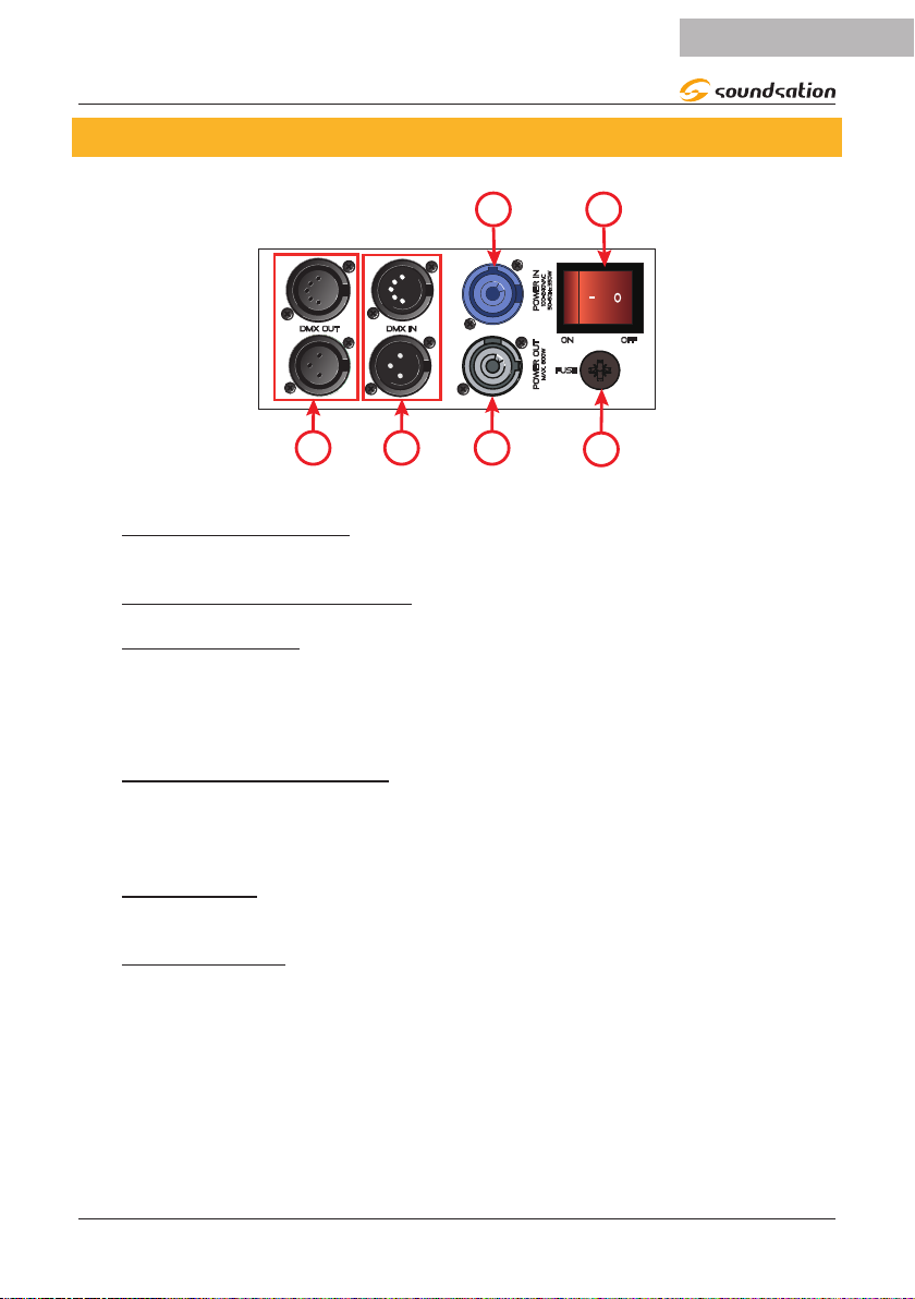
8. REAR PANEL DESCRIPTION
POWER IN
DMX OUT DMX IN
POWER OUT
ENGLISH
350w
Z
100-240VAC
50-60h
OFF
ON
FUSE
mAX. 800W
6
5 4
1) POWER IN SOCKET
Plug the power-cord into an AC socket properly congured for your particular model.
2) POWER ON/OFF SWITCH
3) FUSE HOLDER
Fuse holder with F7AL / 250 V fuse (5 x 20 mm). In case of fuse burn, to prevent the risk
of re and damaging the unit, please use only a spare of the recommended fuse type
as described. Before replacing the fuse, make sure the unit turned o and disconnected
from the AC outlet.
4) POWER OUT SOCKET
Power output socket for power supply to additional SOUNDSATION lights. Ensure that
the total current consumption of all connected devices does not exceed the value spec-
ied on the device in amperes (A).
5) DMX INPUT
Male 3-pin and 5-pin XLR sockets for connection to a DMX control device
6) DMX OUTPUT
Female 3-pin and 5-pin XLR socket for sending the DMX control signal.
13
Page 14

ENGLISH
STD Mode: 17CH
MainMenu
Dmx Address 001
Network
THESIS 740RZ / 1240RZ User manual
9. FUNCTIONS DESCRIPTION
At power on, the device resets all the electrical and mechanical parts. Once the startup procedure is nished, the display will show the current DMX operating mode, the
current operating temperature and the eventual fan speed. If, for example, the device is
set to GUI mode (18CH Mode channel) and the starting address is set to 1, the display
will show:
Temp: 23°C FanSpeed:0000RPM
001
If the device is set in DMX mode and is not connected to a DMX control unit, the main
screen shot will blink. By pressing the [ESC] button twice, the display will show the main
function menu.
9.1. Dmx Address Setting
The Dmx Address setting allows you to set the DMX channel of the machine between
1 and 512. To change it, select the parameter using the [UP] / [DOWN] buttons ( gure
above ) and then, press the [ENTER] button to start the edit. Using again the [UP] /
[DOWN] buttons the DMX Address Value will increase or decrease. Use the [ENTER]
button to conrm, or the [ESC] button to exit without conrming.
14
Fixture
Manual
Information
Factory
Fixture Reset
Display
Page 15

ENGLISH
Fixture
MainMenu
Network
THESIS 740RZ / 1240RZ User manual
9.2. Fixture
By selecting this option using the [UP] / [DOWN] buttons and then pressing the [ENTER] button, you access a submenu consisting of the following options:
Dmx Address 001
Fixture
Manual
Information
Dmx Mode
Run Mode DMX
Pan Invert Close
Tilt Invert
Close
GUI
Factory
Fixture Reset
Display
Dmx Mode
By selecting this option using the [UP] / [DOWN] buttons and then pressing the [ENTER] button, it is possible to select one of the available channel mode.
Using again the [UP] / [DOWN] buttons, you can choose the following modes:
GUI (18CH)
EXT (38CH in the 740RZ model and 58CH in the 1240RZ model)
STD (17CH)
HSI (11CH)
Use the [ENTER] button to conrm, or the [ESC] button to exit without conrming.
Run Mode
By selecting this option using the [UP] / [DOWN] buttons and then pressing the [ENTER] button, it is possible to select one of the available run mode. They are, respec-
tively, the DMX control mode, the Master/Slave mode (named HOST), and the Sound
Control with which the machine is controlled by the sound present in the surrounding
environment.
Using the [UP] / [DOWN] buttons, you can choose the desired run mode.
Use the [ENTER] button to conrm, or the [ESC] button to exit without conrming.
Pan Invert
By selecting this option using the [UP] / [DOWN] buttons and then pressing the [ENTER] button, it is possible to set the PAN Invert parameter. The default setting of this
parameter is “Close”. To invert the Pan, set the parameter to “Open”
Using the [UP] / [DOWN] buttons, you can choose the “Pan Mode”.
Use the [ENTER] button to conrm, or the [ESC] button to exit without conrming.
Note: When the xture is set to HOST but is not connected with other devic
es, the AUTO mode will be activated.
15
Page 16

ENGLISH
Manual
MainMenu
Network
Red 000
THESIS 740RZ / 1240RZ User manual
Tilt Invert
Selecting this option using the [UP] / [DOWN] buttons and then pressing the [ENTER]
button, it is possible to set the TILT Invert parameter. The default setting of this parameter is “Close”. To invert the Tilt, set the parameter to “Open”
Using the [UP] / [DOWN] buttons, you can choose the “Tilt Mode”.
Use the [ENTER] button to conrm, or the [ESC] button to exit without conrming.
9.3. Manual
By selecting this option using the [UP] / [DOWN] buttons and then pressing the [ENTER] button, you access a submenu consisting of the following options:
To select the sub-menu parameters use the [UP] / [DOWN] buttons and then pressing
the [ENTER] button to access the parameter modication.
Using again the [UP] / [DOWN] buttons the value of each parameter will increase or
decrease. Use the [ENTER] button to conrm, or the [ESC] button to exit without conrming.
Pan
Pan adjustment. The range is 0 ÷ 255.
Pan Fine
Fine Pan adjustment. The range is 0 ÷ 255.
Tilt
Tilt adjustment. The range is 0 ÷ 255.
Tilt Fine
Fine Tilt adjustment. The range is 0 ÷ 255.
P/T Speed
Speed adjustment for Pan and Tilt. The range is 0 ÷ 255.
Dim
Adjustment of the light output intensity (Dimmer). The range is 0 ÷ 255.
Strobe
Adjusting the speed of light ashes in the strobe eect. The range is 0 ÷ 255.
Dmx Address 001
Fixture
Manual
Information
Factory
Fixture Reset
Display
Pan
000
Pan Fine 000
Tilt 000
Tilt Fine
000
P/T Speed 000
Dim
Strobe
000
000
16
Page 17

ENGLISH
THESIS 740RZ / 1240RZ User manual
Red
Red color intensity adjustment. The range is 0 ÷ 255.
Green
Green color intensity adjustment. The range is 0 ÷ 255.
Blue
Blue color intensity adjustment. The range is 0 ÷ 255.
White
White color intensity adjustment. The range is 0 ÷ 255
Macro
Scrolling of all color combinations. The range is 0 ÷ 255.
Shape
This function replicates all the combinations of channel 13 of the DMX GUI mode for
both models. The range is 0 ÷ 255.
(Please refer to “10.4. GUI Mode ( 18CH ) THESIS 740RZ” on page 25 or to “10.5. GUI
Mode ( 18CH ) THESIS 1240RZ” on page 27).
Speed
Speed adjustment of the dynamic eects contained in the shape option.
The range is 0 ÷ 255.
Color
Selecting the background color for each eect selected in the shape option.
The range is 0 ÷ 255.
BackDim
Adjusting the brightness of the background selected in the “Color” option.
The range is 0 ÷ 255.
Zoom
Zoom adjustment. The range is 0 ÷ 255 ( 9 °÷ 44 °).
Reset
This function replicates the DMX STD mode Channel 17 controls for both models.
The range is 0 ÷ 255.
(Please refer to “10.1. STD Mode ( 17CH )” on page 22)
17
Page 18

ENGLISH
Information
Temperature
MainMenu
Network
THESIS 740RZ / 1240RZ User manual
9.4. Information
By selecting this option using the [UP] / [DOWN] buttons and then pressing the [ENTER] button, you access a submenu consisting of the following options:
Dmx Address 001
Fixture
Manual
Information
Factory
Fixture Reset
Display
Time
Sensor
Software Version
Time
By selecting this option information on the life cycle of the moving head are shown on
the display:
- Current Time: Partial operating time.
- Total Time: Total operating time.
- Power Count: Number indicating how many times the machine has been
turned On.
Sensor
By selecting this option you will get information on the correct operation of the “Pan,
Tilt, Zoom, Temp and Fan” sensors. When the operation is correct, TRUE is displayed
for each sensor otherwise FALSE will be displayed.
Temperature
By selecting this option, you will have the information concerning the temperature of
the moving head:
- Head Temp: Internal temperature of the moving head.
- Fan Speed: Speed (in RPM) of the fan when it is active. The fan will activate
when the temperature internally exceeds 40 °.
Software Version
Selecting this option, you will get information about the software versions of the
following devices: Panel, Motor, Dimmer e Network. As for Network, the software
version will only be displayed if the optional card is inserted
18
Page 19

ENGLISH
Manual
MainMenu
Network
White
255
THESIS 740RZ / 1240RZ User manual
9.5. Factory
By selecting this option using the [UP] / [DOWN] buttons and then pressing the [ENTER] button, you access a submenu consisting of the following options:
Dmx Address 001
Fixture
Manual
Information
Factory
Fixture Reset
Display
Password
Pan 127
Tilt 127
Zoom
127
Red 255
Green
Blue
000
255
255
All parameters, once set, will be maintained each time the device is turned on. Only the
password must be entered each time to enable the modication of the parameters
contained in this submenu. To select the sub-menu parameters use the [UP] / [DOWN]
buttons and then pressing the [ENTER] button to access the parameter modication.
Using again the [UP] / [DOWN] buttons the value of each parameter will increase or
decrease. Use the [ENTER] button to conrm, or the [ESC] button to exit without conrming.
Password:
The password to be entered is 158. Once the password has been entered, the modication of all other parameters will be enabled.
Pan
Pan ne adjustment for the initial position after switching on. The default value
is 127. The interval is 0 ÷ 255.
Tilt
Tilt ne adjustment for the initial position after switching on. The default value
is 127. The interval is 0 ÷ 255.
Zoom
Zoom ne adjustment for the initial position after switching on. The default
value is 127. The interval is 0 ÷ 255.
Red, Green, Blue, White
Color brightness adjustment. Il valore di default è 255. L’intervallo è 0 ÷ 255.
19
Page 20

ENGLISH
Fixture Reset
MainMenu
Network
Display
Display Flip Normal
Display Mode Show
Language EN
MainMenu
Network
THESIS 740RZ / 1240RZ User manual
9.6. Fixture Reset
By selecting this option using the [UP] / [DOWN] buttons and then pressing the [ENTER] button, you access a submenu consisting of the following options:
Dmx Address 001
Fixture
Motor Reset
Factory Cance
Cance
Manual
Information
Factory
Fixture Reset
Display
Motor Reset
Normally this function is set to “Cance”. Switching to “Run”, using the [UP] / [DOWN]
buttons and then the [ENTER] button, the device will reset the Pan, Tilt and Zoom
motors.
Factory
This function must be used only when you want to reset all the default values. Normally
it is set to “Cance”. Switching to “Run”, using the [UP] / [DOWN] buttons and then the
[ENTER] button, the device will reset all the parameters and functions with the default
values.
9.7. Display
By selecting this option using the [UP] / [DOWN] buttons and then pressing the [ENTER] button, you access a submenu consisting of the following options:
Dmx Address 001
Fixture
Manual
Information
Factory
Fixture Reset
Display
Language
Selects the display language between English and Chinese.
Display Flip
When this parameter is set to “Normal”, the display is in the normal position ;
when “Reverse” is set, the display is in the inverted position.
20
Page 21

ENGLISH
Network
Disable
Universe 000
Protocol ArtNet
MainMenu
Network
IP Address
Subnet Mask
THESIS 1240RZ THESIS 740RZ
THESIS 740RZ / 1240RZ User manual
Display Mode
When this parameter is set to “Show” the display will always remain on. If
instead it is set to “60s”, the display will turn O after 60 seconds if no op-
eration is done. When the display is o, just press any of the control panel
buttons to turn it back On.
9.8. Network
By selecting this option using the [UP] / [DOWN] buttons and then pressing the [ENTER] button, you access a submenu consisting of the following options:
Dmx Address 001
Fixture
Manual
Information
Factory
Fixture Reset
Display
Note: All the parameters contained in this sub-menu will be described in an
addendum owner’s manual related to the optional network board.
10. DMX CHANNEL MODES
The DMX channel modes for both models are 4. In the EXT and GUI modes the DMX
controls are dierent because each model has a dierent number of LEDs. In this
regard, the gure below shows a numbering of the LEDs for both models that will be
used in the tables for the EXT and GUI modes.
L12
L11
L10
L2 L3
L9
L8
L4
L5
L1
L6
L7
KlingNet
L7
L6
L5
L2
L1
L3
L4
.
21
Page 22

ENGLISH
10.1. STD Mode ( 17CH )
Channel Function Value Effect
1 Pan 0 ÷ 255 Pan Rotation
2 Pan Fine 0 ÷ 255 Fine Pan Adjustmnet
3 Tilt 0 ÷ 255 Tilt Rotation
4 Tilt Fine 0 ÷ 255 Fine Tilt Adjustmnet
5 P/T speed 0 ÷ 255 Motor Speed
6 Dim 0 ÷ 255 Dimming
7 DimFine 0 ÷ 255 Fine Dimmer Adjustmnet
8
9 Red 0 ÷ 255 Red Intensity Adjustmnet
10 Green 0 ÷ 255 Green Intensity Adjustmnet
11 Blue 0 ÷ 255 Blue Intensity Adjustmnet
12 White 0 ÷ 255 White Intensity Adjustmnet
13 CCT 0 ÷ 255
14 Macro 0 ÷ 255 Color Macro
15 Eect
16 Zoom 0 ÷ 255 Focus
17 Reset/Prog
Strobe
THESIS 740RZ / 1240RZ User manual
0 ÷ 3 Shut
4 ÷ 103
104 ÷ 107 Open
108 ÷ 207
208 ÷ 212 Open
213 ÷ 225 Random slow strobe
226 ÷ 238
239 ÷ 251 Random fast strobe
252 ÷ 255 Open
0 Shut
1 ÷ 100 Eect of dream
101 ÷ 200 Wave eect
201 ÷ 255 No eect
0 ÷ 59 No eect
60 ÷ 99 All motors reset
100 ÷ 200 Start the auto program
201 ÷ 255 No eect
Regular strobe, speed from
slow to fast
Pulse strobe, speed from slow
to fast
Random medium speed
strobe
White color temperature
adjustment
22
Page 23

ENGLISH
THESIS 740RZ / 1240RZ User manual
10.2. EXT Mode THESIS 740RZ ( 38CH )
Channel Function Value Effect
1 Pan 0 ÷ 255 Pan Rotation
2 Pan Fine 0 ÷ 255 Fine Pan Adjustmnet
3 Tilt 0 ÷ 255 Tilt Rotation
4 Tilt Fine 0 ÷ 255 Fine Tilt Adjustmnet
5 P/T speed 0 ÷ 255 Motor Speed
6 Dim 0 ÷ 255 Dimming
7 DimFine 0 ÷ 255 Fine Dimmer Adjustmnet
0 ÷ 3 Shut
4 ÷ 103
104 ÷ 107 Open
108 ÷ 207
8
9 ÷ 12 R1, G1, B1, W1 0 ÷ 255 LED_1 R-G-B-W
13 ÷ 16 R2, G2, B2, W2 0 ÷ 255 LED_2 R-G-B-W
17 ÷ 20 R3, G3, B3, W3 0 ÷ 255 LED_3 R-G-B-W
21 ÷ 24 R4, G4, B4, W4 0 ÷ 255 LED_4 R-G-B-W
25 ÷ 28 R5, G5, B5, W5 0 ÷ 255 LED_5 R-G-B-W
29 ÷ 32 R6, G6, B6, W6 0 ÷ 255 LED_6 R-G-B-W
33 ÷ 36 R7, G7, B7, W7 0 ÷ 255 LED_7 R-G-B-W
37 Zoom 0 ÷ 255 Focus
38 Reset/Prog
Strobe
208 ÷ 212 Open
213 ÷ 225 Random slow strobe
226 ÷ 238
239 ÷ 251 Random fast strobe
252 ÷ 255 Open
0 ÷ 59 No eect
60 ÷ 99 All motors reset
100 ÷ 200 Start the auto program
201 ÷ 255 No eect
Regular strobe, speed from
slow to fast
Pulse strobe, speed from slow
to fast
Random medium speed
strobe
23
Page 24

ENGLISH
THESIS 740RZ / 1240RZ User manual
10.3. EXT Mode THESIS 1240RZ ( 58CH )
Channel Function Value Effect
1 Pan 0 ÷ 255 Pan Rotation
2 Pan Fine 0 ÷ 255 Fine Pan Adjustmnet
3 Tilt 0 ÷ 255 Tilt Rotation
4 Tilt Fine 0 ÷ 255 Fine Tilt Adjustmnet
5 P/T speed 0 ÷ 255 Motor Speed
6 Dim 0 ÷ 255 Dimming
7 DimFine 0 ÷ 255 Fine Dimmer Adjustmnet
0 ÷ 3 Shut
4 ÷ 103
104 ÷ 107 Open
108 ÷ 207
8
9 ÷ 12 R1, G1, B1, W1 0 ÷ 255 LED_1 R-G-B-W
13 ÷ 16 R2, G2, B2, W2 0 ÷ 255 LED_2 R-G-B-W
17 ÷ 20 R3, G3, B3, W3 0 ÷ 255 LED_3 R-G-B-W
21 ÷ 24 R4, G4, B4, W4 0 ÷ 255 LED_4 R-G-B-W
25 ÷ 28 R5, G5, B5, W5 0 ÷ 255 LED_5 R-G-B-W
29 ÷ 32 R6, G6, B6, W6 0 ÷ 255 LED_6 R-G-B-W
33 ÷ 36 R7, G7, B7, W7 0 ÷ 255 LED_7 R-G-B-W
37 ÷ 40 R8, G8, B8, W8 0 ÷ 255 LED_8 R-G-B-W
41 ÷ 44 R9, G9, B9, W9 0 ÷ 255 LED_9 R-G-B-W
45 ÷ 48 R10, G10, B10, W10’ 0 ÷ 255 LED_10 R-G-B-W
49 ÷ 52 R11, G11, B11, W11 0 ÷ 255 LED_11 R-G-B-W
53 ÷ 56 R12, G12, B12, W12 0 ÷ 255 LED_12 R-G-B-W
57 Zoom 0 ÷ 255 Focus
58 Reset/Prog
Strobe
208 ÷ 212 Open
213 ÷ 225 Random slow strobe
226 ÷ 238
239 ÷ 251 Random fast strobe
252 ÷ 255 Open
0 ÷ 59 No eect
60 ÷ 99 All motors reset
100 ÷ 200 Start the auto program
201 ÷ 255 No eect
Regular strobe, speed from
slow to fast
Pulse strobe, speed from slow
to fast
Random medium speed
strobe
24
Page 25

THESIS 740RZ / 1240RZ User manual
10.4. GUI Mode ( 18CH ) THESIS 740RZ
Channel Function Value Effect
1 Pan 0 ÷ 255 Pan Rotation
2 Pan Fine 0 ÷ 255 Fine Pan Adjustmnet
3 Tilt 0 ÷ 255 Tilt Rotation
4 Tilt Fine 0 ÷ 255 Fine Tilt Adjustmnet
5 P/T speed 0 ÷ 255 Motor Speed
6 Dim 0 ÷ 255 Dimming
0 ÷ 3 Shut
4 ÷ 103 Regular strobe, speed from slow to fast
104 ÷ 107 Open
108 ÷ 207 Pulse strobe, speed from slow to fast
7 Strobe
8 Red 0 ÷ 255 Red Intensity Adjustmnet
9 Green 0 ÷ 255 Green Intensity Adjustmnet
10 Blue 0 ÷ 255 Blue Intensity Adjustmnet
11 White 0 ÷ 255 White Intensity Adjustmnet
12 Macro 0 ÷ 255 Color Macro
13 Combination
208 ÷ 212 Open
213 ÷ 225 Random slow strobe
226 ÷ 238 Random medium speed strobe
239 ÷ 251 Random fast strobe
252 ÷ 255 Open
0 Shut
1 ÷ 6 LED 1 on
7 ÷ 13 LED 2 on
14 ÷ 20 LED 3 on
21 ÷ 27 LED 4 on
28 ÷ 34 LED 5 on
35 ÷ 41 LED 6 on
42 ÷ 48 LED 7 on
49 ÷ 55 LED 2, LED 3 On
56 ÷ 62 LED 4, LED 5 On
63 ÷ 69 LED 6, LED 7 On
70 ÷ 76 LED 1, LED 2, LED 3 On
77 ÷ 83 LED 1, LED 4 LED 5 On
84 ÷ 90 LED 1, LED 6 LED 7 On
91 ÷ 97 LED 1, LED 2 On
98 ÷104 LED 3, LED 6 On
105 ÷111 LED2, LED 3, LED 5, LED 6 On
112 ÷118 LED 1, LED 3, LED 6 On
119 ÷125 LED 2, LED 4, LED 6 On
126 ÷ 132 LED 1, LED2, LED 3, LED 5, LED 6 On
ENGLISH
25
Page 26

ENGLISH
13 Combination
14 Speed 0 ÷ 255 Graphic eect speed selection
15 Shape Back 0 ÷ 255 Graphic background color selection
16 BackDim 0 ÷ 255 Background brightness from light to dark
17 Zoom 0 ÷ 255 Focus
18 Reset/Prog
THESIS 740RZ / 1240RZ User manual
133 ÷ 139 LED 2, LED3, LED 4, LED 5, LED 6, LED 7 On
140 ÷146
147 ÷ 153
154 ÷ 160
161 ÷ 167
168 ÷174
175 ÷181
182 ÷188
189 ÷195
196 ÷ 202
203 ÷ 209
210 ÷ 216
217 ÷223
224 ÷ 230
231 ÷ 237 Color petal wave eect
238 ÷ 244 Color petal rotation eect
245 ÷ 255 Colorful rotation eect
0 ÷ 59 No eect
60 ÷ 99 All motors reset
100 ÷ 200 Start the auto program
201 ÷ 255 No eect
LED2 to LED7 LEDs will light up dynamically
one at a time
The LED2 to LED7 LEDs will light up two at a
time dynamically
LED 1 always on;
LED2 to LED7 LEDs will light up dynamically
one at a time
3 LEDs will light up alternately:
(L1, L2, L3) - (L1, L4, L5) - (L1, L6, L7)
3 LEDs will light up alternately in circular
mode
LED 1 always on;
3 LEDs will light up alternately in circular
mode
2 LEDs will alternately turn on in the oppo-
site angle in circular mode
4 LEDs will alternately turn on in the oppo-
site angle in circular mode
LED 1 always on;
2 LEDs will alternately turn on in the oppo-
site angle in circular mode
LED 1 always on;
4 LEDs will alternately turn on in the oppo-
site angle in circular mode
The following groups of LEDs will light up
alternatively: (L2, L3) - (L1, L4, L7) - (L5, L6)
The central LED (L1) and all the other LEDs
will turn on alternately
The central LED (L1) and all the other LEDs
will be lit alternately together with a se-
quence of colors
26
Page 27

THESIS 740RZ / 1240RZ User manual
10.5. GUI Mode ( 18CH ) THESIS 1240RZ
Channel Function Value Effect
1 Pan 0 ÷ 255 Pan Rotation
2 Pan Fine 0 ÷ 255 Fine Pan Adjustmnet
3 Tilt 0 ÷ 255 Tilt Rotation
4 Tilt Fine 0 ÷ 255 Fine Tilt Adjustmnet
5 P/T speed 0 ÷ 255 Motor Speed
6 Dim 0 ÷ 255 Dimming
0 ÷ 3 Shut
4 ÷ 103 Regular strobe, speed from slow to fast
104 ÷ 107 Open
108 ÷ 207 Pulse strobe, speed from slow to fast
7 Strobe
8 Red 0 ÷ 255 Red Intensity Adjustmnet
9 Green 0 ÷ 255 Green Intensity Adjustmnet
10 Blue 0 ÷ 255 Blue Intensity Adjustmnet
11 White 0 ÷ 255 White Intensity Adjustmnet
12 Macro 0 ÷ 255 Color Macro
13 Combination
208 ÷ 212 Open
213 ÷ 225 Random slow strobe
226 ÷ 238 Random medium speed strobe
239 ÷ 251 Random fast strobe
252 ÷ 255 Open
0 Shut
1 ÷ 6 LED 1 on
7 ÷ 13 LED 2 on
14 ÷ 20 LED 3 on
21 ÷ 27 LED 4 on
28 ÷ 34 LED 5 on
35 ÷ 41 LED 6 on
42 ÷ 48 LED 7 on
49 ÷ 55 LED 8 on
56 ÷ 62 LED 9 on
63 ÷ 69 LED 10 on
70 ÷ 76 LED 11 on
77 ÷ 83 LED 12 on
84 ÷ 90 LED1, LED6, LED7 On
91 ÷ 97 LED2, LED9, LED10 On
98 ÷ 104 LED3, LED4, LED12 On
105 ÷ 111 LED1, LED6, LED7, LED8 On
112 ÷ 118 LED2, LED9, LED10, LED11 On
119 ÷ 125 LED3, LED4, LED5, LED12 On
126 ÷ 132 LED1, LED2, LED8 On
ENGLISH
27
Page 28

ENGLISH
13 Combination
14 Speed 0 ÷ 255 Graphic eect speed selection
15 Shape Back 0 ÷ 255 Graphic background color selection
16 BackDim 0 ÷ 255 Background brightness from light to dark
17 Zoom 0 ÷ 255 Focus
18 Reset/Prog
THESIS 740RZ / 1240RZ User manual
133 ÷ 139 LED2, LED3, LED11 On
140 ÷ 146 LED1, LED3, LED5 On
147 ÷ 153 LED1, LED2, LED3 On
154 ÷ 160 da LED4 a LED12 On
161 ÷ 167 LED1, LED2, LED3, LED5, LED8, LED11 On
168 ÷ 174
175 ÷ 181
182 ÷188
189 ÷195
196 ÷ 202
203 ÷ 209
210 ÷ 216
217 ÷ 223 Windmill rotation eect
224 ÷ 230 Dynamic eect of petal blooming
231 ÷ 237 Color petal blooming eect
238 ÷ 244 Color petal wave eect
245 ÷ 251 Color petal rotation eect
252 ÷ 255 Color rotation eect
0 ÷ 59 No eect
60 ÷ 99 All motors reset
100 ÷ 200 Start the auto program
201 ÷ 255 No eect
The L4 to L12 LEDs will light up one at a
time dynamically
The L4 to L12 LEDs will light up two at a
time dynamically
The L4 to L12 LEDs will light up three at a
time dynamically
3 LEDs will light up alternately:
(L1, L2, L8) - (L2, L3, L11) - (L1, L3, L5)
4 LEDs will light up alternately:
(L3, L4, L5, L12) - (L1, L6, L7, L8)
(L2, L9, L10, L11)
The following groups of LEDs will light up
alternatively:
(L7, L8, L9) - (L1, L2, L6, L10) - (L3, L5, L11)
(L12, L4)
The following groups of LEDs will light up
alternatively:
(L1, L6, L7) - (L2, L9, L10) - (L3, L4, L11)
28
Page 29

THESIS 740RZ / 1240RZ User manual
10.6. HSI Mode ( 11CH )
Channel Function Value Effect
1 Pan 0 ÷ 255 Pan Rotation
2 Pan Fine 0 ÷ 255 Fine Pan Adjustmnet
3 Tilt 0 ÷ 255 Tilt Rotation
4 Tilt Fine 0 ÷ 255 Fine Tilt Adjustmnet
5 P/T speed 0 ÷ 255 Motor Speed
0 ÷ 3 Shut
4 ÷ 103
104 ÷ 107 Open
108 ÷ 207
6 Strobe
7 Hue 0 ÷ 255 Color Scale
8 Saturation 0 ÷ 255 Saturation
9 Intensity 0 ÷ 255 Luminance
10 Zoom 0 ÷ 255 Focus
11 Reset/Prog
208 ÷ 212 Open
213 ÷ 225 Random slow strobe
226 ÷ 238
239 ÷ 251 Random fast strobe
252 ÷ 255 Open
0 ÷ 59 No eect
60 ÷ 99 All motors reset
100 ÷ 200 Start the auto program
201 ÷ 255 No eect
Regular strobe, speed from
slow to fast
Pulse strobe, speed from slow
to fast
Random medium speed
strobe
ENGLISH
29
Page 30

ENGLISH
THESIS 740RZ / 1240RZ User manual
11. SPECIFICATION
THESIS 740RZ THESIS 1240RZ
LED light 7 x 40W RGBW OSRAM® 12 x 40W RGBW OSRAM®
LED Lifespan 5000 Hours
Voltage 100V-240V 50-60Hz
Power consumption 400W 600W (7R)
Amperage 2,5A
Control mode DMX512, Master/Slave, Auto, Sound
Channel Mode 18CH, 38CH, 17CH, 11CH 18CH, 58CH, 17CH, 11CH
Network function Support RDM, Art-Net®, Kling-Net and sACN networking protocols (Optional)
Beam angle (Scan type) 4,5° ÷ 45°
Dimmer 0-100% (16bit )
CCT 2800K-8500K
Zoom
X/Y scan Pan 540°,Tilt:270°
Strobe 1-20Hz
Display 2” Color LCD, English and Chinese switchable languages, Reversible
Housing Flame-retardant plastic
Internal Running Temp.. 0 ÷ 40°C
Dimensions (W,D,H) 290 x 225 x 380 mm 395 x 265 x 410 mm
Weight 8.9 kg 14.35 kg
Package Dimensions (W,D,H) 310 x 250 x 430 mm 420 x 290 x 430 mm
Package Weight 10 Kg 17 Kg
9° ÷ 44° /1.7s, with 3 silent motors at the same time to provide
accurate zooming, stable beam, without skating
Note: Our products are subject to a process of continual further development. Therefore modications to the
technical features remain subject to change without further notice.
30
Page 31

ENGLISH
THESIS 740RZ / 1240RZ User manual
12. WARRANTY AND SERVICE
All SOUNDSATION products feature a limited two-year warranty. This two-year warranty is specic to the date of purchase as shown on your purchase receipt.
The following cases/components are not covered from the above warranty:
• Any accessories supplied with the product
• Improper use
• Fault due to wear and tear
• Any modication of the product eected by the user or a third party
SOUNDSATION shall satisfy the warranty obligations by remedying any material or
manufacturing faults free of charge at SOUNDSATION’s discretion either by repair or by
exchanging individual parts or the entire appliance. Any defective parts removed from
a product during the course of a warranty claim shall become the property of SOUNDSATION.
While under warranty period, defective products may be returned to your local
SOUNDSATION dealer together with original proof of purchase. To avoid any damag-
es in transit, please use the original packaging if available. Alternatively you can send
the product to SOUNDSATION SERVICE CENTER – Via Enzo Ferrari , 10 – 62017 Porto
Recanati - Italy . In order to send a product to service center you need an RMA number.
Shipping charges have to be covered by the owner of the product.
For further information please visit www.soundsationmusic.com
31
Page 32

ENGLISH
THESIS 740RZ / 1240RZ User manual
13. WARNING
PLEASE READ CAREFULLY – EU and EEA (Norway, Iceland and Liechtenstein) only
This symbol indicates that this product is not to be disposed of with your household
waste, according to the WEEE Directive (2202/96/EC) and your national law.
This product should be handed over to a designated collection point, e.g., on an
authorized one-for-one basis when you buy a new similar product or to an authorized
collection site for recycling waste electrical and electronic equipment (WEEE).
Improper handling of this type of waste could have a possible negative impact on the
environment and human health due to potentially hazardous substances that are gen-
erally associated with EEE. At the same time, your cooperation in the correct disposal of
this product will contribute to the eective usage of natural resources.
For more information about where you can drop o your waste equipment for recycling, please contact your local city oce, waste authority, approved WEEE scheme or
your household waste disposal service.
32
Page 33

ITALIANO
MANUALE D’USO THESIS 740RZ / 1240RZ
SOMMARIO
1. INTRODUZIONE .......................................................................................................36
1.1. DISIMBALLAGGIO ................................................................................................................................................36
1.2. Accessori .................................................................................................................................................................37
2. DESCRIZIONE GENERALE ........................................................................................37
3. CARATTERISTICHE PRINCIPALI ..............................................................................37
4. CONNESSIONI DI RETE ...........................................................................................38
5. CONNESSIONE DMX ...............................................................................................38
5.1. Terminatore DMX .................................................................................................................................................39
5.2. Cavi DMX 3-Poli / 5-Poli ....................................................................................................................................39
6. INSTALLAZIONE.......................................................................................................40
7. DESCRIZIONE DEL PANNELLO FRONTALE ............................................................42
8. DESCRIZIONE DEL PANNELLO POSTERIORE ........................................................43
9. DESCRIZIONE DELLE FUNZIONI .............................................................................44
9.1. Dmx Address..........................................................................................................................................................44
9.2. Fixture .......................................................................................................................................................................45
9.3. Manual .....................................................................................................................................................................46
9.4. Information .............................................................................................................................................................48
9.5. Factory ......................................................................................................................................................................49
9.6. Fixture Reset ...........................................................................................................................................................50
9.7. Display ......................................................................................................................................................................50
9.8. Network ...................................................................................................................................................................51
10. MODALITÀ CANALE DMX .......................................................................................51
10.1. Modalità STD ( 17CH ) .......................................................................................................................................52
10.2. Modalità EXT ( 38CH ) THESIS 740RZ ..........................................................................................................53
10.3. Modalità EXT ( 58CH ) THESIS 1240RZ ........................................................................................................54
10.4. Modalità GUI ( 18CH ) THESIS 740RZ ..........................................................................................................55
10.5. Modalità GUI ( 18CH ) THESIS 1240RZ ........................................................................................................57
10.6. Modalità HSI ( 11CH ).........................................................................................................................................59
11. SPECIFICHE ...............................................................................................................60
12. GARANZIA E ASSISTENZA ...................................................................................... 61
13. AVVISO .....................................................................................................................62
33
Page 34

ITALIANO
MANUALE D’USO THESIS 740RZ / 1240RZ
IMPORTANTI SIMBOLI DI SICUREZZA
Il simbolo è usato per indicare che in questa apparecchiatura sono
presenti alcuni terminali sotto tensione pericolosi, anche in condizioni
di normale funzionamento, che possono costituire rischio di scosse
elettriche o di morte.
Il simbolo viene utilizzato nella documentazione di servizio per indicare
che uno specico componente può essere sostituito esclusivamente
dal componente specicato nella documentazione per motivi di sicu-
rezza.
Terminale di Terra
Corrente/Tensione alternata
Terminale in tensione pericoloso
Indica che l’apparato è acceso.
Indica che l’apparato è spento.
WARNING:
CAUTION: Precauzioni da osservare per evitare danni all’apparecchio.
0.5m
Precauzioni da osservare per evitare il pericolo di ferimento o di morte
per l’utilizzatore.
Per proteggere l’ambiente, provare a riciclare il materiale di imballaggio
il più possibile
Il proiettore è solo per uso interno (IP20). Usare solo in luoghi asciutti.
Tenere il dispositivo lontano da pioggia e umidità, calore eccessivo,
umidità e polvere. Non permettere il contatto con acqua o altri liquidi
o oggetti metallici.
Non gettare via questo prodotto come spazzatura generica, si prega
di trattare il prodotto seguendo la normativa sui prodotti elettronici
abbandonati nel proprio paese.
Posizionare l’apparecchio in un luogo ben ventilato, lontano da ma-
teriali inammabili e / o liquidi. L’apparecchio deve essere ssato ad
almeno 50 cm dalle pareti circostanti.
CURA DEL PRODOTTO
f Leggete queste istruzioni
f Conservate queste istruzioni
f Rispettate tutte le avvertenze
f Seguite tutte le istruzioni
34
Page 35

ITALIANO
MANUALE D’USO THESIS 740RZ / 1240RZ
1) ACQUA / UMIDITA
The apparatus should be protected from moisture and rain and can not be used near
water; for example near a bathtub, a kitchen sink, a swimming pool, etc.
2) CONDENSAZIONE
Per evitare la formazione di condensa all’interno, lasciare che questa unità si adatti alle
temperature circostanti quando viene trasportata in una stanza calda dopo il trasporto.
A volte la condensa impedisce all’unità di funzionare a pieno ritmo o può addirittura
causare danni.
3) CALORE
L’apparecchio deve essere posto lontano da fonti di calore come radiatori, stufe o altri
apparecchi che producono calore. Non usare il dispositivo quando la temperatura ambiente massima è superiore a 40 °C.
4) VENTILAZIONE
Non ostruite le prese d’aria per la ventilazione: ciò potrebbe provocare incendi. Installate sempre l’unità secondo le istruzioni del produttore.
5) Introduzione di oggetti e liquidi
Non introdurre oggetti o versare liquidi all’interno dell’apparato per ragioni di sicurezza.
6) Cavo di alimentazione e spina
Evitate che il cavo di alimentazione venga calpestato o schiacciato, in particolare in
prossimità delle spine, delle prese e del punto in cui fuoriesce dall’apparecchio. Non
vanicate la nalità di sicurezza della spina con messa a terra. Una spina normale o
“polarizzata” ha due soli terminali; una spina con messa a terra ha un terzo polo di
terra. Questo ulteriore terminale serve per la vostra sicurezza. Se la spina fornita non si
inserisce nella presa, consultate un elettricista per l’eventuale sostituzione.
7) ALIMENTAZIONE
L’apparecchio deve essere collegato alla sorgente di alimentazione elettrica del tipo
indicato sull’apparecchio o descritto nel manuale. In caso contrario si potrebbero
provocare danni al prodotto ed eventualmente all’utente. Staccate la spina in caso di
temporali o quando non viene utilizzato per lunghi periodi di tempo.
8) CONNESSIONE ELETTRICA
Disconnettersi sempre dalla fonte di alimentazione prima di riparare o sostituire il fusibile e assicurarsi di sostituirlo con lo stesso tipo e dimensioni di fusibile. Interrompere
l’alimentazione prima di spostare, riparare e pulire l’unità. Un cablaggio elettrico errato
può invalidare la garanzia del prodotto.
Per evitare scosse elettriche, tutti gli apparecchi devono essere collegati a circuiti con
una presa a terra adatta. Non accendere e spegnere l’apparecchio in breve tempo.
35
Page 36

ITALIANO
MANUALE D’USO THESIS 740RZ / 1240RZ
9) FUSIBILE
Per evitare il rischio di incendi e di danni all’unità, utilizzate solo il tipo di fusibile descritto nel manuale. Prima di sostituire il fusibile, assicuratevi che l’apparecchio sia spento e scollegato dalla presa di corrente.
10) CONNESSIONE DMX
Quando si usa il controller DMX, assicurarsi che non vi siano fonti di interferenza (ad
esempio: Intercom, onde radio ad alta frequenza e sorgenti di radiazioni).
11) PULIZIA
Pulire solo con un panno asciutto. Non utilizzare solventi come benzolo o alcol.
12) Manutenzione
Non eettuate qualsiasi altro intervento al di fuori di quelli descritti nel manuale. Per
eventuale assistenza rivolgetevi solo a personale qualicato. Utilizzate solo accessori /
componenti suggeriti dal produttore.
1. INTRODUZIONE
Grazie per aver acquistato la nostra testa mobile THESIS 740RZ. Godetevi la tua nuova
attrezzatura e assicuratevi di leggere attentamente questo manuale prima di mettere in
funzione il dispositivo!
Questo manuale utente è stato creato per fornire sia una panoramica dei controlli, sia
informazioni su come usarli. Per aiutarvi a capire le connessioni tra i vari controlli, questi
sono stati riuniti in gruppi in base alle loro funzioni.
1.1. DISIMBALLAGGIO
La testa mobile SPIRE BEAM è stata accuratamente imballata per garantire un trasporto
sicuro. Nonostante questo, si consiglia di esaminare attentamente il pacchetto e il suo
contenuto per eventuali segni di danni sici, che possono vericarsi durante il trasporto. Ogni unità ha le seguenti parti:
f Una Testa Mobile
f Un Cavo di alimentazione (Presa EU - PowerCon)
f Un Cavo DMX (3-Pin XLR da Maschio a Femmina)
f Due Morsetti (tipo Omega)
f Un Manuale di istruzioni
ATTENZIONE: La confezione non è un giocattolo! Tenere fuori dalla portata
dei bambini! Conservare in un luogo sicuro il materiale di imballaggio originale per uso futuro.
36
Page 37

ITALIANO
MANUALE D’USO THESIS 740RZ / 1240RZ
In caso di danni durante il trasporto, informare immediatamente lo spedizioniere e
conservare il materiale di imballaggio per l’ispezione. Ancora una volta, si prega di
conservare il cartone e tutti i materiali di imballaggio. Se l’apparecchiatura deve essere
restituita al produttore, è importante che l’apparecchiatura venga restituita nella confezione originale del produttore e nell’imballaggio. Si prega di non intraprendere alcuna
azione senza prima contattarci.
1.2. Accessori
SOUNDSATION può fornire una vasta gamma di accessori di qualità che è possibile
utilizzare con la testa mobile della serie SPIRE, come cavi, splitter, controller DMX e una
vasta gamma di altri proiettori.
Tutti i prodotti del catalogo SOUNDSATION sono stati a lungo testati con questo
dispositivo quindi si consiglia di utilizzare accessori originali e parti di ricambio Soundsation.
Chiedete al vostro rivenditore SOUNDSATION o consultate il nostro Sito Web www.
soundsationmusic.com per tutti gli accessori necessari a garantire le migliori prestazioni
del prodotto.
2. DESCRIZIONE GENERALE
La serie THESIS di teste mobili SOUNDSATION ore due nuovi modelli di washlight con,
rispettivamente, 7 e 12 potenti e adabili LED da 40W OSRAM. Rappresentano una
valida alternativa alle lampade a ioduri di metallo con tutti i beneci della tecnologia
LED: basso consumo, maggiore durata, minore dissipazione della temperatura. Il fascio
luminoso varia da 4.5° a 45° grazie allo ZOOM controllato da 3 motori simultaneamente che conferiscono una regolazione estremamente morbida e silenziosa.
Il sistema di miscelazione dei colori in quadricromia, la temperatura-colore regolabile,
il dimmer accurato e lineare, uniti al sosticato controllo dei singoli pixel fanno delle
nuove teste mobili THESIS dei validi strumenti di lavoro capaci di valorizzare la creatività dei light designer più esigenti. Numerose sono le funzioni di combinazione dei Pixel:
arcobaleno, pixel singolo, cerchio, controllo complete dei singoli colori di ogni LED, e
molti altri.
Particolare attenzione è dedicata alla precisione e silenziosità dei movimenti meccanici.
PAN e TILT sono dotati di motori trifase con controllo a 16-bit. Lo ZOOM è gestito da 3
motori per ridurre al minimo lo skating e le vibrazioni. Il Dimmer elettronico è accurato
e morbido. Anche la velocità delle ventole è controllato elettronicamente in funzione
della temperatura interna, garantendo un giusto equilibrio tra silenziosità, sicurezza e
durata dei chip LED.
3. CARATTERISTICHE PRINCIPALI
f Luci LED: 7 x 40W (THESIS 740RZ) / 12 x 40W (THESIS 1240RZ) RGBW OSRAM® con
durata di vita dei LED di circa 50000 ore
37
Page 38

ITALIANO
f Angolo Beam (tipo scan) ): da 4.5°a 45°
f Dimmer elettronico graduale con controllo a 16 bit
f Strobo: 1-20Hz con modalità di lavoro ON e OFF a luce istantanea
f Miscelazione RGBW di colori uniformi con eetti Pixel, come arcobaleno, singolo
pixel, cerchio, controllo completo, miscelazione ssa di colori di sfondo ssi, pattern di luce di fondo sso, controllo di pixel luminosi di fondo ssi.
f Funzione ZOOM da 9 ° a 44 ° / 1,7 secondi, con 3 motori silenziosi e simultanei per
fornire zoom accurato, raggio stabile ed omogeneità di eetto
f PAN e TILT con scansione a 8-16 bit, reset fotoelettrico e funzione di correzione
automatica degli errori.
f Modalità di controllo DMX512, Master-Slave, Auto e Sound
f Quattro modalità DMX: 17CH standard, 38CH/58CH (740RZ/1240RZ) estesa, 18CH
pattern, 11CH HIS
f Sistema di rareddamento ad alta ecienza con monitoraggio della temperatura.
Nessun rischio di danni alla lampada a LED; Ventola con controllo intelligente della
velocità e monitoraggio della velocità di rotazione.
f Display a colori LCD da 2,0 “con una facile interfaccia utente
f Funzione di alimentazione esterna con connessione USB per l’impostazione dei
parametri della testa mobile tramite display.
f Supporta i protocolli di rete RDM, Art-Net®, Kling-Net e SACN (Optionali)
MANUALE D’USO THESIS 740RZ / 1240RZ
4. CONNESSIONI DI RETE
Collegare il dispositivo alla rete elettrica con il cavo di alimentazione in dotazione. Si
prega di notare che la tensione di alimentazione e la frequenza siano le stesse della
tensione e della frequenza del dispositivo quando si collega l’alimentazione. La corrispondenza dei li è la seguente:
Cavo (EU) Piedino Internazionale
Marrone Fase L
Blu Neutro N
Giallo/Verde Terra
La terra deve essere collegata! Prestare attenzione alla sicurezza! Prima di
mettere in funzione per la prima volta, l’installazione deve essere approvata
da un esperto
5. CONNESSIONE DMX
Gli apparecchi DMX sono progettati per ricevere dati attraverso una catena seriale a
cascata. Questo tipo di connessione permette di connettere il DATA OUT di un dispositivo al DATA IN del dispositivo successivo. L’ordine in cui i dispositivi sono collegati
non è importante e non ha alcun eetto su come un controllore comunica a ciascuna
38
Page 39

ITALIANO
W
Terminatore DMX
MANUALE D’USO THESIS 740RZ / 1240RZ
apparecchiatura. Utilizzare un ordine che preveda il cablaggio più semplice e diretto
DMX Termonator
Uso dei 3-Piedini nei Connettori XLR per DMX
USCITAINGRESSO
DMX 512
Unit 1 Unit 2 Last Unit
3-Poli XLR
Piedino 1: MASSA
Piedino 2: DMX Piedino 3: DMX +
Collegare i dispositivi utilizzando un cavo bipolare schermato a 2 conduttori con
connettori XLR maschio-femmina a 3 poli. La connessione dello schermo è il piedino 1,
mentre il piedino 2 è negativo (S-)e il piedino 3 è positivo (S +).
ATTENZIONE: I li non devono entrare in contatto l’uno con l’altro; altrimenti
i dispositivi non funzioneranno aatto o non funzioneranno correttamente.
5.1. Terminatore DMX
DMX è un protocollo di comunicazione elastico, tuttavia si potrebbero vericare occasionalmente degli errori. Le terminazioni riducono gli errori di segnale, e quindi le
migliori applicazioni includono l’uso di una terminazione in tutte le circostanze. Se si
vericano problemi con un comportamento irregolare dell’apparecchio, specialmente
sulla lunghezza dei cavi di segnale, un terminale può aiutare a migliorare le prestazioni.
Il terminatore DMX è semplicemente un connettore XLR con un resistore da 120Ω
(ohm), 1/4 Watt collegato attraverso il segnale (-) e il segnale (+), rispettivamente, i pin
2 e 3, che viene quindi inserito nella presa di uscita sull’ultimo proiettore nella catena.
Le connessioni sono illustrate di seguito.
120ohm, 1/4
resistenza
Un cavo di segnale DMX standard può trasmette segnali a 20 unità al massi-
mo. E’ necessario un amplicatore di segnale per collegare più apparecchi.
5.2. Cavi DMX 3-Poli / 5-Poli
I protocolli di connessione DMX utilizzati dai produttori di controller e apparecchi non
sono standardizzati in tutto il mondo.Tuttavia, due sono gli standard più comuni: XLR
39
Page 40

ITALIANO
MANUALE D’USO THESIS 740RZ / 1240RZ
a 5 poli e sistema XLR a 3 poli. Se si desidera collegare MOOD 185 WASH a un dispositivo di ingresso XLR a 5 poli è necessario utilizzare un cavo adattatore o farlo da soli
seguendo la corrispondenza di cablaggio tra gli standard di spina e presa a 3 e 5 poli
5-Pins XLR (socket)
Pin 1: GND (Screen)
Pin 2: Signal (-)
Pin 3: Signal (+)
Pin 4: N/C
Pin 5: N/C
3-Pins XLR (socket)
Pin 1: GND (Screen)
Pin 2: Signal (-)
Pin 3: Signal (+)
3-Pins XLR (plug)
Pin 1: GND (Screen)
Pin 2: Signal (-)
Pin 3: Signal (+)
5-Pins XLR (plug)
Pin 1: GND (Screen)
Pin 2: Signal (-)
Pin 3: Signal (+)
Pin 4: N/C
Pin 5: N/C
6. INSTALLAZIONE
Prestare attenzione alla sicurezza! Si prega di considerare rispettivamente la
EN 60598-2-17 e lo standard nazionale durante l’installazione. Il rivenditore
autorizzato deve eseguire solo l’installazione.
L’installazione dell’apparecchiatura deve essere fatta e costruita in modo da poter
reggere 10 volte il peso per 1 ora senza problemi di demolizione. L’installazione deve
essere sempre assicurata con un accessorio di sicurezza secondario, come ad esempio
una rete di cattura adeguata. Questo accessorio di sicurezza secondario deve essere
costruito in modo che nessuna parte dell’installazione possa cadere se l’attacco principale dovesse non funzionare.
E vietato installare, disinstallare o eettuare manutenzione su ponti, luoghi di lavoro
sopraelevati e in altre aree pericolose o ad alto rischio . L’operatore deve assicurarsi
che le misure di sicurezza e l’installazione tecnica della macchina siano approvate da un
esperto prima di essere messa in funzione per la prima volta ed anche, dopo even-
tuali modiche, prima di essere rimessa ancora in funzione. Assicurarsi che un esperto
approvi le misure di sicurezza e l’installazione tecnica della macchina almeno una volta
all’anno.
AVVERTIMENTO: Il dispositivo deve essere installato fuori da aree dove le
persone possano sedersi o camminare.
IMPORTANTE: Le installazioni su impalcature alte richiedono una grande
esperienza, incluso (ma non limitato a) il calcolo dei limiti di carico del materiale di installazione utilizzato per il quale va eettuata una ispezione periodica di sicurezza estesa anche al proiettore. In assenza di tali requisiti, non
si deve tentare l’installazione da soli, avvalendosi invece di un installatore
professionale di tali strutture. Un’installazione errata può provocare lesioni
personali o danni materiali.
Nel caso di riposizionamento in basso dell’attrezzatura ssata a sotto o su travetti alti,
utilizzare sempre sistemi di tralicci professionali. L’apparecchio non deve mai essere
installato in modo che possa oscillare liberamente. Prima del montaggio, accertarsi
40
Page 41

ITALIANO
5
1
2
MANUALE D’USO THESIS 740RZ / 1240RZ
che il punto di installazione possa reggere un carico minimo di 10 volte il peso del
proiettore.
ATTENZIONE: Il dispositivo può causare gravi lesioni in caso di collisione.
In caso di dubbi sulla sicurezza di una possibile installazione, non installare
l’apparecchiatura!
ATTENZIONE: Utilizzare due morsetti appropriati per ssare l’apparecchio su
tralicci o travature . Seguire le istruzioni indicate nella parte inferiore della
base. Assicurarsi che il dispositivo sia stato sistemato correttamente e che la
struttura (traliccio) a cui si sta ssando i proiettori sia sicura.
PERICOLO DI FUOCO! Durante l’installazione del dispositivo, assicurarsi che
non vi siano materiali altamente inammabili (articoli di decorazione, ecc.)
entro una distanza minima di 0,5 metri.
La testa mobile può essere posizionata direttamente sul pavimento oppure montata
con qualsiasi orientamento su un traliccio o travatura, senza alterarne le caratteristiche
di funzionamento. Si prega di fare riferimento alla foto qui sotto e seguire rigorosamente le istruzioni.
4
2
3
6
90°
5
5
f Utilizzare morsetti adatti alla sezione del traliccio su cui si desidera ssare la testa
mobile.
f Inserire la vite nel foro centrale della staa n.2 e serrare il dado fornito con il mor-
setto (e le eventuali rondelle fornite sempre con il morsetto).
f Posizionare i tappi con le alette n.3 nella direzione dei fori n.5 posti sotto la base
della testa mobile. Avvitarli in senso orario per circa 90 °, no a quando si sentirà
un clic che indica il raggiungimento della posizione corretta e sicura.
f Agganciare la testa mobile al traliccio o travatura tramite i due morsetti già per-
fettamente ssati alla base, e avvitare la vite ad aletta n.4 in modo da stringere la
testa mobile ed evitare il più possibile vibrazioni durante l’uso del dispositivo.
f Quando la testa mobile è posizionata in alto, installare sempre un cavo di sicurezza
41
Page 42

ITALIANO
1
2
3
4
5
6
MANUALE D’USO THESIS 740RZ / 1240RZ
che possa reggere almeno 10 volte il peso del dispositivo. Agganciare il cavo di
sicurezza al foro n.6 situato sotto la base della testa mobile.
7. DESCRIZIONE DEL PANNELLO FRONTALE
STD Mode: 17CH
Temp: 23 C FanSpeed:0000RPM
001
UPDATE
UP
ENTER INVERTESC
DOWN
7
1) DISPLAY GRAFICO LCD
Mostra la modalità operativa e altre informazioni di sistema.
2) CONNESSIONE DI ALIMENTAZIONE USB
Funzione di alimentazione esterna con connessione USB (per power bank, laptop, etc.)
per l’impostazione dei parametri della testa mobile tramite display senza che questa
venga accesa usando il pulsante di accensione.
3) PULSANTE ESC
Premere questo pulsante per uscire dalle funzioni senza variazione dei parametri o
premere ripetutamente per tornare alla videata principale.
4) PULSANTE UP
Utilizzare questo pulsante per scorrere verso l’alto le voci nel menu di selezione e nei
sottomenu per le impostazioni di sistema (DMX Address, dispositivo, manuale, ecc.).
Premere questo pulsante anche per aumentare i valori e le impostazioni dei parametri.
5) PULSANTE INVERT
Premendo questo pulsante, il display ruoterà di 180 °. Questo può essere utile per
l’installazione dall’alto. Dopo aver spento il dispositivo, il display tornerà alla posizione
normale alla successiva accensione.
6) PULSANTE DOWN
Utilizzare questo pulsante per scorrere verso il basso le voci nel menu di selezione
e nei sottomenu per le impostazioni di sistema (DMX Address, xture, manual, ecc.).
42
Page 43

ITALIANO
3
21
MANUALE D’USO THESIS 740RZ / 1240RZ
Premere questo pulsante anche per decrementare i valori e le impostazioni dei parametri.
8. DESCRIZIONE DEL PANNELLO POSTERIORE
350w
Z
100-240VAC
50-60h
DMX OUT DMX IN
POWER IN
ON
FUSE
mAX. 800W
POWER OUT
OFF
6
5 4
1) PRESA DI ALIMENTAZIONE
Collegare il cavo di alimentazionea questa presa ed a una presa CA correttamente
congurata per il modello specico
2) Interruttore di accensione/spegnimento (On/Off)
3) PORTAFUSIBILE
Portafusibile con fusibile F7AL / 250 V (5 x 20 mm). In caso di bruciatura del fusibile, per
prevenire il rischio di incendio e di danneggiare l’unità, utilizzare solo un tipo di fusibile
consigliato come descritto. Prima di sostituire il fusibile, assicurarsi che l’unità sia spenta e scollegata dalla presa di corrente.
4) PRESA DI ALIMENTAZIONE PER DISPOSITIVI ESTERNI
Presa di alimentazione per ulteriori dispositivi luci SOUNDSATION. Assicurarsi che il
consumo di corrente totale di tutti le apparecchiature collegate non superi il valore
specicato in ampere (A) sulla testa mobile.
5) Ingressi DMX
Prese di ingresso XLR maschio a 3 e 5 pin per il collegamento a un dispositivo di controllo DMX
6) USCITE DMX
Presa di uscita XLR femmina a 3 e 5 pin per l’invio del segnale di controllo DMX.
43
Page 44

ITALIANO
STD Mode: 17CH
MainMenu
Dmx Address 001
Network
MANUALE D’USO THESIS 740RZ / 1240RZ
9. DESCRIZIONE DELLE FUNZIONI
All’accensione, il dispositivo resettaa tutte le parti elettriche e meccaniche. Al termine
della procedura di avvio, il display mostrerà la modalità operativa DMX corrente, la
temperatura operativa corrente e l’eventuale velocità della ventola. Se, ad esempio, il
dispositivo è impostato in modalità GUI (modalità 18CH) e l’indirizzo iniziale è impostato su 1, il display mostrerà:
Temp: 23°C FanSpeed:0000RPM
001
Se il dispositivo è impostato in modalità DMX e non è collegato a un’unità di controllo
DMX, la schermata principale lampeggerà. Premendo due volte il tasto [ESC], il display
mostrerà il menu delle funzioni principali
9.1. Dmx Address
Questa funzione consente di impostare il canale DMX della macchina tra 1 e 512. Per
modicare l’indirizzo, selezionare il parametro utilizzando i pulsanti [UP] / [DOWN]
e quindi, premere il pulsante [ENTER] per iniziare la modica. Usando nuovamente i
pulsanti [UP] / [DOWN] si aumenterà / diminuirà il valore dell’indirizzo DMX. Utilizzare il
pulsante [ENTER] per confermare o il pulsante [ESC] per uscire senza confermare.
44
Fixture
Manual
Information
Factory
Fixture Reset
Display
Page 45

ITALIANO
Fixture
MainMenu
Network
MANUALE D’USO THESIS 740RZ / 1240RZ
9.2. Fixture
Selezionando questa opzione usando i pulsanti [UP] / [DOWN] e quindi premendo il
pulsante [ENTER], si accede a un sottomenu composto dalle seguenti voci:
Dmx Mode
Selezionando questa opzione usando i pulsanti [UP] / [DOWN] e quindi premendo il
pulsante [ENTER], è possibile selezionare una delle modalità di canale disponibili. Utilizzando di nuovo i pulsanti [UP] / [DOWN], è possibile scegliere le seguenti modalità:
GUI (18CH)
EXT (38CH nel modello 740RZ e 58CH nel modello1240RZ )
STD (17CH)
HSI (11CH)
Utilizzare il pulsante [ENTER] per confermare o il pulsante [ESC] per uscire senza confermare.
Run Mode
Selezionando questa opzione usando i pulsanti [UP] / [DOWN] e quindi premendo
il pulsante [ENTER], è possibile scegliere una delle modalità di esecuzione disponi-
bili. Sono, rispettivamente, la modalità di controllo DMX, la modalità Master / Slave
(denominata HOST) e la modalità SOUND con cui la macchina è controllata dal suono
presente nell’ambiente circostante.
Utilizzando i pulsanti [UP] / [DOWN], è possibile scegliere la modalità di esecuzione
desiderata.
Usare il pulsante [ENTER] per confermare o il pulsante [ESC] per uscire senza confermare.
Dmx Address 001
Fixture
Manual
Information
Dmx Mode
Run Mode DMX
Pan Invert Close
Tilt Invert
Close
GUI
Factory
Fixture Reset
Display
Nota: Quando l’apparecchio è impostato su HOST ma non è collegato ad altri
dispositivi, verrà attivata la modalità AUTO.
Pan Invert
Selezionando questa opzione usando i pulsanti [UP] / [DOWN] e quindi premendo il
pulsante [ENTER], è possibile impostare il parametro PAN Invert. L’impostazione pre-
45
Page 46

ITALIANO
Manual
MainMenu
Network
Red 000
MANUALE D’USO THESIS 740RZ / 1240RZ
denita di questo parametro è “Close”. Per invertire il Pan, impostare il parametro su
“Open”. Usando i pulsanti [UP] / [DOWN], si può scegliere la “Modalità Pan”.
Utilizzare il pulsante [ENTER] per confermare o il pulsante [ESC] per uscire senza confer-
mare.
Tilt Invert
Selezionando questa opzione usando i pulsanti [UP] / [DOWN] e quindi premendo
il pulsante [ENTER], è possibile impostare il parametro TILT Invert. L’impostazione
predenita di questo parametro è “Close”. Per invertire il Tilt, impostare il parametro su
“Open”. Usando i pulsanti [UP] / [DOWN], si può scegliere la “Modalità Pan”.
Utilizzare il pulsante [ENTER] per confermare o il pulsante [ESC] per uscire senza confer-
mare.
9.3. Manual
Selezionando questa opzione usando i pulsanti [SU] / [GIÙ] e quindi premendo il pulsante [ENTER], si accede a un sottomenu composto dalle seguenti voci:
Per scegliere i parametri del sottomenu utilizzare i pulsanti [UP] / [DOWN] e quindi
premere il pulsante [ENTER] per accedere alla modica dei parametri.
Usando di nuovo i pulsanti [UP] o [DOWN], il valore parametro selezionato aumenta o
diminuisce. Utilizzare il pulsante [ENTER] per confermare o il pulsante [ESC] per uscire
senza confermare.
Pan
Regolazione del Pan. L’intervallo è 0 ÷ 255.
Pan Fine
Regolazione ne del Pan. L’intervallo è 0 ÷ 255.
Tilt
Regolazione del Tilt. L’intervallo è 0 ÷ 255.
Tilt Fine
Regolazione ne del Tilt. L’intervallo è 0 ÷ 255.
P/T Speed
Regolazione della velocità per il Pan e il Tilt. L’intervallo è 0 ÷ 255.
Dmx Address 001
Fixture
Manual
Information
Factory
Fixture Reset
Display
Pan
000
Pan Fine 000
Tilt 000
Tilt Fine
000
P/T Speed 000
Dim
Strobe
000
000
46
Page 47

ITALIANO
MANUALE D’USO THESIS 740RZ / 1240RZ
Dim
Regolazione dell’intensità dell’emissione luminosa (Dimmer). L’intervallo è 0 ÷255.
Strobe
Regola la velocità dei ash nell’eetto strobo. L’intervallo è 0 ÷ 255.
Red
Regolazione dell’intensità del colore rosso. L’intervallo è 0 ÷ 255.
Green
Regolazione dell’intensità del colore verde. L’intervallo è 0 ÷ 255.
Blue
Regolazione dell’intensità del colore blù. L’intervallo è 0 ÷ 255.
White
Regolazione dell’intensità del colore bianco. L’intervallo è 0 ÷ 255.
Macro
Scorrimento di tutte le combinazioni dei colori. L’intervallo è 0 ÷ 255.
Shape
Questa funzione replica tutte le combinazioni del canale 13 della modalità DMX GUI
per entrambe i modelli. L’intervallo è 0 ÷ 255.
(Fare riferimento a “10.4. Modalità GUI ( 18CH ) THESIS 740RZ” a pagina 55 oppure
a “10.5. Modalità GUI ( 18CH ) THESIS 1240RZ” a pagina 57).
Speed
Regolazione della velocità degli eetti dinamici contenuti nell’opzione “Shape”.
L’intervallo è 0 ÷ 255
Color
Selezione del colore di sfondo per ogni eetto selezionato nell’opzione “Shape”.
L’intervallo è 0 ÷ 255.
BackDim
Regolazione della luminosità dello sfondo selezionato nell’opzione “Color”.
L’intervallo è 0 ÷ 255.
Zoom
Regolazione dello Zoom. L’intervallo è 0 ÷ 255 ( 9 °÷ 44 °).
Reset
Questa funzione replica i controlli del canale 17 della modalità DMX STD. Per entrambe
i modelli. L’intervallo è 0 ÷ 255.
(Fare riferimento a “10.1. Modalità STD ( 17CH )” a pagina 52).
47
Page 48

ITALIANO
Information
Temperature
MainMenu
Network
MANUALE D’USO THESIS 740RZ / 1240RZ
9.4. Information
Selezionando questa opzione usando i pulsanti [SU] / [GIÙ] e quindi premendo il pulsante [ENTER], si accede a un sottomenu composto dalle seguenti voci:
Dmx Address 001
Fixture
Manual
Information
Factory
Fixture Reset
Display
Time
Sensor
Software Version
Time
Selezionando questa opzione, si ottengono le informazioni relative al ciclo di vita della
testa mobile:
- Current Time: Tempo parziale di funzionamento.
- Total Time: Tempo totale di funzionamento.
- Power Count: Numero di accensioni.
Sensor
Selezionando questa opzione si ottengono le informazioni relative al corretto funzionamento dei sensori: Pan, Tilt, Zoom, Temp e Fan. Quando il funzionamento è corretto
viene visualizzato TRUE per ogni sensore altrimenti verrà visualzzato FALSE.
Temperature
Selezionando questa opzione, si ottengono le informazioni relative all temperatura
della testa mobile:
- Head Temp: Temperatura interna della testa mobile.
- Fan Speed: Velocità (in RPM) della ventola quando è attiva. La ventola si
attiverà quando internamente la temperatura supererà i 40°.
Software Version
Selezionando questa opzione, si ottengono le informazioni relative alle versioni del
software dei seguenti dispositivi: Panel, Motor, Dimmer e Network.
Per quanto riguarda Network, la versione software verrà visualizzata soltanto se la
scheda opzionale è inserita.
48
Page 49

ITALIANO
Manual
MainMenu
Network
White
255
MANUALE D’USO THESIS 740RZ / 1240RZ
9.5. Factory
Selezionando questa opzione usando i pulsanti [SU] / [GIÙ] e quindi premendo il pulsante [ENTER], si accede a un sottomenu composto dalle seguenti voci:
Tutti i parametri, una volta impostati, saranno mantenuti ad ogni accensione del
dispositivo. Soltanto la password dovrà essere immessa ogni volta per abilitare la
modica dei parametri contenuti in questo sottomenu. Per scegliere i parametri del
sottomenu utilizzare i pulsanti [UP] / [DOWN] e quindi premere il pulsante [ENTER]
per accedere alla modica dei parametri. Usando di nuovo i pulsanti [UP] o [DOWN], il
valore parametro selezionato aumenta o diminuisce. Utilizzare il pulsante [ENTER] per
confermare o il pulsante [ESC] per uscire senza confermare.
Password
La password da immettere è 158. Una volta inserita la password si abiliterà la
modica a tutti gli altri parametri.
Pan
Regolazione ne del Pan per la posizione iniziale dopo l’accensione. Il valore di default
è 127. L’intervallo è 0 ÷ 255.
Tilt
Regolazione ne del Tilt per la posizione iniziale dopo l’accensione. Il valore di default
è 127. L’intervallo è 0 ÷ 255.
Zoom
Regolazione ne dello Zoom per la posizione iniziale dopo l’accensione. Il valore di
default è 127. L’intervallo è 0 ÷ 255.
Red, Green, Blue, White
Regolazione iniziale della luminosità dei colori. Il valore di default è 255. L’intervallo è
0 ÷ 255.
Dmx Address 001
Fixture
Manual
Information
Factory
Fixture Reset
Display
Password
000
Pan 127
Tilt 127
Zoom
127
Red 255
Green
Blue
255
255
49
Page 50

ITALIANO
Fixture Reset
MainMenu
Network
Display
Display Flip Normal
Display Mode Show
Language EN
MainMenu
Network
MANUALE D’USO THESIS 740RZ / 1240RZ
9.6. Fixture Reset
Selezionando questa opzione usando i pulsanti [SU] / [GIÙ] e quindi premendo il pulsante [ENTER], si accede a un sottomenu composto dalle seguenti voci:
Dmx Address 001
Fixture
Motor Reset
Factory Cance
Cance
Manual
Information
Factory
Fixture Reset
Display
Motor Reset
Normalmente questa fuzione è impostata su “Cance”. Passando a “Run”, utilizzando i
pulsanti [UP] / [DOWN] e quindi il pulsante [ENTER], il dispositivo eettuerà il reset dei
motori Pan, Tilt e Zoom.
Factory
Questa funzione deve essere utilizzata soltanto quando si vogliono reimpostare tutti
i valori di default. Normalmente questa è impostata su “Cance”. Quando si passa a
“Run”, utilizzando i pulsanti [UP] / [DOWN] e quindi il pulsante [ENTER], il dispositivo
resetterà tutti i parametri e le funzioni con i valori di default.
9.7. Display
Selezionando questa opzione usando i pulsanti [SU] / [GIÙ] e quindi premendo il pulsante [ENTER], si accede a un sottomenu composto dalle seguenti voci:
Dmx Address 001
Fixture
Manual
Information
Factory
Fixture Reset
Display
Language
Seleziona la lingua di visualizzazione tra inglese e cinese.
Display Flip
Quando questo parametro è “Normal”, il display è in posizione normale;
Quando è “Reverse” il display è rovesciato.
50
Page 51

ITALIANO
Network
Disable
Universe 000
Protocol ArtNet
MainMenu
Network
IP Address
Subnet Mask
THESIS 1240RZ THESIS 740RZ
MANUALE D’USO THESIS 740RZ / 1240RZ
Display Mode
Quando questo parametro è impostato su “Show” il display rimarrà sempre
acceso. Se invece viene impostato su “60s”, il display si spegnerà dopo 60
secondi se non viene eseguita alcuna operazione. Quando il display è spento, basterà premere uno qualunque dei pulsanti del pannelo di controllo per
riaccenderlo.
9.8. Network
Selezionando questa opzione usando i pulsanti [SU] / [GIÙ] e quindi premendo il pulsante [ENTER], si accede a un sottomenu composto dalle seguenti voci:
Dmx Address 001
Fixture
Manual
Information
Factory
Fixture Reset
Display
Note: Tutti i parametri contenuti in questo sottomenu saranno descritti in un
aggiuntivo manuale di istruzioni relativo alla scheda Network opzionale.
10. MODALITÀ CANALE DMX
Le modalita canale DMX per entrambe i modelli sono 4. Nelle modalita EXT e GUI i
controlli DMX sono diversi poichè ogni modello ha un dierente numero di LED. A tal
proposito nella gura seguente viene riportata una numerazione dei LED per entrambe
i modelli che verrà usata nelle tabelle per le modalità EXT e GUI.
L12
L11
L10
L2 L3
L9
L8
L4
L5
L1
L6
L7
KlingNet
L7
L6
L5
L2
L1
L3
L4
51
Page 52

ITALIANO
10.1. Modalità STD ( 17CH )
Canale Funzione Intervallo Valori Effetto
1 Pan 0 ÷ 255 Rotazione Pan
2 Pan Fine 0 ÷ 255 Regolazione ne del Pan
3 Tilt 0 ÷ 255 Rotazione Tilt
4 Tilt Fine 0 ÷ 255 Regolazione ne del Tilt
5 P/T speed 0 ÷ 255 Velocità Motore
6 Dim 0 ÷ 255 Dimming
7 Dim Fine 0 ÷ 255 Regolazione ne del Dimmer
8 Strobo
9 Rosso 0 ÷ 255 Regolazione intensità Rosso
10 Verde 0 ÷ 255 Regolazione intensità Verde
11 Blù 0 ÷ 255 Regolazione intensità Blù
12 Bianco 0 ÷ 255 Regolazione intensità Bianco
13 CCT 0 ÷ 255
14 Macro 0 ÷ 255 Macro Colori
15 Eetto
16 Zoom 0 ÷ 255 Focus
17 Reset/Prog
MANUALE D’USO THESIS 740RZ / 1240RZ
0 ÷ 3 Chiusa
4 ÷ 103
104 ÷ 107 Aperta
108 ÷ 207
208 ÷ 212 Aperta
213 ÷ 225 Strobo lenta Casuale
226 ÷ 238
239 ÷ 251 Strobo Veloce Casuale
252 ÷ 255 Aperta
0 Chiusa
1 ÷ 100 Eetto Sogno
101 ÷ 200 Eetto Onda
201 ÷ 255 Nessun Eetto
0 ÷ 59 Nessun Eetto
60 ÷ 99 Reset dei Motori
100 ÷ 200 Avvia il programma Auto
201 ÷ 255 Nessun Eetto
Strobo regolare, velocità da
lenta a veloce
Strobo a impulsi, velocità da
lenta a veloce
Strobo Casuale con velocità
media
Regolazione temperatura del
colore bianco
52
Page 53

MANUALE D’USO THESIS 740RZ / 1240RZ
10.2. Modalità EXT ( 38CH ) THESIS 740RZ
Canale Funzione Intervallo Valori Effetto
1 Pan 0 ÷ 255 Rotazione Pan
2 Pan Fine 0 ÷ 255 Regolazione ne del Pan
3 Tilt 0 ÷ 255 Rotazione Tilt
4 Tilt Fine 0 ÷ 255 Regolazione ne del Tilt
5 P/T speed 0 ÷ 255 Velocità Motore
6 Dim 0 ÷ 255 Dimming
7 Dim Fine 0 ÷ 255 Regolazione ne del Dimmer
0 ÷ 3 Chiusa
4 ÷ 103
104 ÷ 107 Aperta
108 ÷ 207
8 Strobo
9 ÷ 12 R1, G1, B1, W1 0 ÷ 255 LED_1 R-G-B-W
13 ÷ 16 R2, G2, B2, W2 0 ÷ 255 LED_2 R-G-B-W
17 ÷ 20 R3, G3, B3, W3 0 ÷ 255 LED_3 R-G-B-W
21 ÷ 24 R4, G4, B4, W4 0 ÷ 255 LED_4 R-G-B-W
25 ÷ 28 R5, G5, B5, W5 0 ÷ 255 LED_5 R-G-B-W
29 ÷ 32 R6, G6, B6, W6 0 ÷ 255 LED_6 R-G-B-W
33 ÷ 36 R7, G7, B7, W7 0 ÷ 255 LED_7 R-G-B-W
37 Zoom 0 ÷ 255 Focus
38 Reset/Prog
208 ÷ 212 Aperta
213 ÷ 225 Strobo lenta Casuale
226 ÷ 238
239 ÷ 251 Strobo Veloce Casuale
252 ÷ 255 Aperta
0 ÷ 59 Nessun Eetto
60 ÷ 99 Reset dei Motori
100 ÷ 200 Avvia il programma Auto
201 ÷ 255 Nessun Eetto
Strobo regolare, velocità da
lenta a veloce
Strobo a impulsi, velocità da
lenta a veloce
Strobo Casuale con velocità
media
ITALIANO
53
Page 54

ITALIANO
MANUALE D’USO THESIS 740RZ / 1240RZ
10.3. Modalità EXT ( 58CH ) THESIS 1240RZ
Canale Funzione Intervallo Valori Effetto
1 Pan 0 ÷ 255 Rotazione Pan
2 Pan Fine 0 ÷ 255 Regolazione ne del Pan
3 Tilt 0 ÷ 255 Rotazione Tilt
4 Tilt Fine 0 ÷ 255 Regolazione ne del Tilt
5 P/T speed 0 ÷ 255 Velocità Motore
6 Dim 0 ÷ 255 Dimming
7 Dim Fine 0 ÷ 255 Regolazione ne del Dimmer
0 ÷ 3 Chiusa
4 ÷ 103
104 ÷ 107 Aperta
108 ÷ 207
8
9 ÷ 12 R1, G1, B1, W1 0 ÷ 255 LED_1 R-G-B-W
13 ÷ 16 R2, G2, B2, W2 0 ÷ 255 LED_2 R-G-B-W
17 ÷ 20 R3, G3, B3, W3 0 ÷ 255 LED_3 R-G-B-W
21 ÷ 24 R4, G4, B4, W4 0 ÷ 255 LED_4 R-G-B-W
25 ÷ 28 R5, G5, B5, W5 0 ÷ 255 LED_5 R-G-B-W
29 ÷ 32 R6, G6, B6, W6 0 ÷ 255 LED_6 R-G-B-W
33 ÷ 36 R7, G7, B7, W7 0 ÷ 255 LED_7 R-G-B-W
37 ÷ 40 R8, G8, B8, W8 0 ÷ 255 LED_8 R-G-B-W
41 ÷ 44 R9, G9, B9, W9 0 ÷ 255 LED_9 R-G-B-W
45 ÷ 48 R10, G10, B10, W10’ 0 ÷ 255 LED_10 R-G-B-W
49 ÷ 52 R11, G11, B11, W11 0 ÷ 255 LED_11 R-G-B-W
53 ÷ 56 R12, G12, B12, W12 0 ÷ 255 LED_12 R-G-B-W
57 Zoom 0 ÷ 255 Focus
58 Reset/Prog
Strobo
208 ÷ 212 Aperta
213 ÷ 225 Strobo lenta Casuale
226 ÷ 238
239 ÷ 251 Strobo Veloce Casuale
252 ÷ 255 Aperta
0 ÷ 59 Nessun Eetto
60 ÷ 99 Reset dei Motori
100 ÷ 200 Avvia il programma Auto
201 ÷ 255 Nessun Eetto
Strobo regolare, velocità da
lenta a veloce
Strobo a impulsi, velocità da
lenta a veloce
Strobo Casuale con velocità
media
54
Page 55

MANUALE D’USO THESIS 740RZ / 1240RZ
10.4. Modalità GUI ( 18CH ) THESIS 740RZ
Canale Funzione Intervallo Valori Effetto
1 Pan 0 ÷ 255 Rotazione Pan
2 Pan Fine 0 ÷ 255 Regolazione ne del Pan
3 Tilt 0 ÷ 255 Rotazione Tilt
4 Tilt Fine 0 ÷ 255 Regolazione ne del Tilt
5 P/T speed 0 ÷ 255 Velocità Motore
6 Dim 0 ÷ 255 Dimming
0 ÷ 3 Chiusa
4 ÷ 103 Strobo regolare, velocità da lenta a veloce
104 ÷ 107 Aperta
108 ÷ 207 Strobo a impulsi, velocità da lenta a veloce
7 Strobe
8 Red 0 ÷ 255 Regolazione intensità Rosso
9 Green 0 ÷ 255 Regolazione intensità Verde
10 Blue 0 ÷ 255 Regolazione intensità Blù
11 White 0 ÷ 255 Regolazione intensità Bianco
12 Macro 0 ÷ 255 Macro Colori
13 Combinationi
208 ÷ 212 Aperta
213 ÷ 225 Strobo lenta Casuale
226 ÷ 238 Strobo Casuale con velocità media
239 ÷ 251 Strobo Veloce Casuale
252 ÷ 255 Aperta
0 Tutti i LED Accesi
1 ÷ 6 LED 1 On
7 ÷ 13 LED 2 On
14 ÷ 20 LED 3 On
21 ÷ 27 LED 4 On
28 ÷ 34 LED 5 On
35 ÷ 41 LED 6 On
42 ÷ 48 LED 7 On
49 ÷ 55 LED 2, LED 3 On
56 ÷ 62 LED 4, LED 5 On
63 ÷ 69 LED 6, LED 7 On
70 ÷ 76 LED 1, LED 2, LED 3 On
77 ÷ 83 LED 1, LED 4 LED 5 On
84 ÷ 90 LED 1, LED 6 LED 7 On
91 ÷ 97 LED 1, LED 2 On
98 ÷104 LED 3, LED 6 On
105 ÷111 LED2, LED 3, LED 5, LED 6 On
112 ÷118 LED 1, LED 3, LED 6 On
119 ÷125 LED 2, LED 4, LED 6 On
126 ÷ 132 LED 1, LED2, LED 3, LED 5, LED 6 On
ITALIANO
55
Page 56

ITALIANO
13 Combinationi
14 Speed 0 ÷ 255 Selezione della velocità degli eetti
15 Shape Back 0 ÷ 255
16 BackDim 0 ÷ 255
17 Zoom 0 ÷ 255 Focus
18 Reset/Prog
MANUALE D’USO THESIS 740RZ / 1240RZ
133 ÷ 139 LED 2, LED3, LED 4, LED 5, LED 6, LED 7 On
140 ÷146
147 ÷ 153
154 ÷ 160
161 ÷ 167
168 ÷174
175 ÷181
182 ÷188
189 ÷195
196 ÷ 202
203 ÷ 209
210 ÷ 216
217 ÷223
224 ÷ 230
231 ÷ 237 Eetto petali colorati
238 ÷ 244 Eetto petali colorati con rotazione
245 ÷ 255 Eetto di rotazione dei colori
0 ÷ 59 Nessun Eetto
60 ÷ 99 Reset dei Motori
100 ÷ 200 Avvia il programma Auto
201 ÷ 255 Nessun Eetto
I LED da LED2 a LED7 si illumineranno uno
alla volta dinamicamente
I LED da LED2 a LED7 si illumineranno due
alla volta dinamicamente
LED 1 sempre acceso;
I LED da LED2 a LED7 si illumineranno uno
alla volta dinamicamente
Si accenderanno alternativamente 3 LED:
(L1, L2, L3) - (L1, L4, L5) - (L1, L6, L7)
Si accenderanno alternativamente 3 LED in
modo circolare
LED 1 sempre acceso;
Si accenderanno alternativamente 3 LED in
modo circolare
Si accenderanno alternativamente 2 LED su
angolo opposto in modo circolare
Si accenderanno alternativamente 4 LED su
angolo opposto in modo circolare
LED 1 sempre acceso;
Si accenderanno alternativamente 2 LED su
angolo opposto in modo circolare
LED 1 sempre acceso;
Si accenderanno alternativamente 4 LED su
angolo opposto in modo circolare
Si accenderanno alternativamente i seg-
uenti gruppi di LED:
(L2, L3) - (L1, L4, L7) - (L5, L6)
Si accenderanno alternativamente il LED
centrale (L1) e tutti gli altri LED insieme.
Si accenderanno alternativamente il LED
centrale (L1) e tutti gli altri LED insieme
con una sequenza di colori.
Selezione del colore di sfondo per ogni
eetto
Luminosità dello sfondo da luminoso a
scuro
56
Page 57

MANUALE D’USO THESIS 740RZ / 1240RZ
10.5. Modalità GUI ( 18CH ) THESIS 1240RZ
Canale Funzione Intervallo Valori Effetto
1 Pan 0 ÷ 255 Rotazione Pan
2 Pan Fine 0 ÷ 255 Regolazione ne del Pan
3 Tilt 0 ÷ 255 Rotazione Tilt
4 Tilt Fine 0 ÷ 255 Regolazione ne del Tilt
5 P/T speed 0 ÷ 255 Velocità Motore
6 Dim 0 ÷ 255 Dimming
0 ÷ 3 Chiusa
4 ÷ 103 Strobo regolare, velocità da lenta a veloce
104 ÷ 107 Aperta
108 ÷ 207 Strobo a impulsi, velocità da lenta a veloce
7 Strobe
8 Red 0 ÷ 255 Regolazione intensità Rosso
9 Green 0 ÷ 255 Regolazione intensità Verde
10 Blue 0 ÷ 255 Regolazione intensità Blù
11 White 0 ÷ 255 Regolazione intensità Bianco
12 Macro 0 ÷ 255 Macro Colori
13 Combinationi
208 ÷ 212 Aperta
213 ÷ 225 Strobo lenta Casuale
226 ÷ 238 Strobo Casuale con velocità media
239 ÷ 251 Strobo Veloce Casuale
252 ÷ 255 Aperta
0 Tutti i LED Accesi
1 ÷ 6 LED1 On
7 ÷ 13 LED2 On
14 ÷ 20 LED3 On
21 ÷ 27 LED4 On
28 ÷ 34 LED5 On
35 ÷ 41 LED6 On
42 ÷ 48 LED7 On
49 ÷ 55 LED8 On
56 ÷ 62 LED9 On
63 ÷ 69 LED10 On
70 ÷ 76 LED11 On
77 ÷ 83 LED12 On
84 ÷ 90 LED1, LED6, LED7 On
91 ÷ 97 LED2, LED9, LED10 On
98 ÷ 104 LED3, LED4, LED12 On
105 ÷ 111 LED1, LED6, LED7, LED8 On
112 ÷ 118 LED2, LED9, LED10, LED11 On
119 ÷ 125 LED3, LED4, LED5, LED12 On
126 ÷ 132 LED1, LED2, LED8 On
ITALIANO
57
Page 58

ITALIANO
13 Combinationi
14 Speed 0 ÷ 255 Selezione della velocità degli eetti
15 Shape Back 0 ÷ 255
16 BackDim 0 ÷ 255
17 Zoom 0 ÷ 255 Focus
18 Reset/Prog
MANUALE D’USO THESIS 740RZ / 1240RZ
133 ÷ 139 LED2, LED3, LED11 On
140 ÷ 146 LED1, LED3, LED5 On
147 ÷ 153 LED1, LED2, LED3 On
154 ÷ 160 da LED4 a LED12 On
161 ÷ 167 LED1, LED2, LED3, LED5, LED8, LED11 On
168 ÷ 174
175 ÷ 181
182 ÷188
189 ÷195
196 ÷ 202
203 ÷ 209
210 ÷ 216
217 ÷ 223 Eetto di rotazione “Mulino a Vento)
224 ÷ 230 Eetto dinamico “oritura dei petali””
231 ÷ 237
238 ÷ 244 Eetto Petali colorati
245 ÷ 251 Eetto di rotazione colori a gruppi di 4 LED
252 ÷ 255 Eetto di rotazione dei colori
0 ÷ 59 Nessun Eetto
60 ÷ 99 Reset dei Motori
100 ÷ 200 Avvia il programma Auto
201 ÷ 255 Nessun Eetto
I LED da LED4 a LED12 si illumineranno
uno alla volta dinamicamente
I LED da LED4 a LED12 si illumineranno due
alla volta dinamicamente
I LED da LED4 a LED12 si illumineranno tre
alla volta dinamicamente
Si accenderanno alternativamente 3 LED:
(L1, L2, L8) - (L2, L3, L11) - (L1, L3, L5)
Si accenderanno alternativamente 4 LED:
(L3, L4, L5, L12) - (L1, L6, L7, L8)
(L2, L9, L10, L11)
Si accenderanno alternativamente i seg-
uenti gruppi di LED:
(L7, L8, L9) - (L1, L2, L6, L10) - (L3, L5, L11)
(L12, L4)
Si accenderanno alternativamente i seg-
uenti gruppi di LED:
(L1, L6, L7) - (L2, L9, L10) - (L3, L4, L11)
Eetto dinamico “oritura dei petali” con
diversi colori
Selezione del colore di sfondo per ogni
eetto
Luminosità dello sfondo da luminoso a
scuro
58
Page 59

MANUALE D’USO THESIS 740RZ / 1240RZ
10.6. Modalità HSI ( 11CH )
Canale Funzione Intervallo Valori Effetto
1 Pan 0 ÷ 255 Rotazione Pan
2 Pan Fine 0 ÷ 255 Regolazione ne del Pan
3 Tilt 0 ÷ 255 Rotazione Tilt
4 Tilt Fine 0 ÷ 255 Regolazione ne del Tilt
5 P/T speed 0 ÷ 255 Velocità Motore
0 ÷ 3 Chiusa
4 ÷ 103
104 ÷ 107 Aperta
108 ÷ 207
6 Strobe
7 Hue 0 ÷ 255 Scala Colori
8 Saturation 0 ÷ 255 Saturazione
9 Intensity 0 ÷ 255 Luminanza
10 Zoom 0 ÷ 255 Focus
11 Reset/Prog
208 ÷ 212 Aperta
213 ÷ 225 Strobo lenta Casuale
226 ÷ 238
239 ÷ 251 Strobo Veloce Casuale
252 ÷ 255 Aperta
0 ÷ 59 Nessun Eetto
60 ÷ 99 Reset dei Motori
100 ÷ 200 Avvia il programma Auto
201 ÷ 255 Nessun Eetto
Strobo regolare, velocità da
lenta a veloce
Strobo a impulsi, velocità da
lenta a veloce
Strobo Casuale con velocità
media
ITALIANO
59
Page 60

ITALIANO
MANUALE D’USO THESIS 740RZ / 1240RZ
11. SPECIFICHE
THESIS 740RZ THESIS 1240RZ
Luci LED 7 x 40W RGBW OSRAM® 12 x 40W RGBW OSRAM®
Durata LED 5000 Ore
Voltaggio 100V-240V 50-60Hz
Consumo Energia 400W 600W (7R)
Amperaggio 2,5A
Modalità di controllo DMX512, Master/Slave, Auto, Sound
Modalità Canale 18CH, 38CH, 17CH, 11CH 18CH, 58CH, 17CH, 11CH
Funzione Network Supporta i protocolli di rete RDM, Art-Net®, Kling-Net e SACN (Optionale)
Angolo Beam (Tipo Scan) 4,5° ÷ 45°
Dimmer 0-100% (16bit )
CCT 2800K-8500K
Zoom
X/Y scan Pan 540°,Tilt:270°
Strobo 1-20Hz
Display LCD a Colori da 2 “; Selezione lingue tra Inglese e Cinese; Rovesciabile
Alloggiamento Plastica ignifuga
Temperatura interna di
lavoro.
Dimensioni (L,P,A) 290 x 225 x 380 mm 395 x 265 x 410 mm
Peso 8.9 kg 14.35 kg
Dimensioni Imballo (L,P,A) 310 x 250 x 430 mm 420 x 290 x 430 mm
Peso Imballo 10 Kg 17 Kg
Nota: I nostri prodotti sono soggetti ad un processo di continuo ed ulteriore sviluppo. Le caratteristiche tecniche
sono soggette a modiche senza preavviso
Da 9 ° a 44 ° / 1,7 secondi, con 3 motori silenziosi e simultanei per fornire zoom
accurato, raggio stabile ed omogeneità di eetto
0 ÷ 40°C
60
Page 61

ITALIANO
MANUALE D’USO THESIS 740RZ / 1240RZ
12. GARANZIA E ASSISTENZA
Tutti i prodotti SOUNDSATION dispongono di una garanzia di due anni. Questa garanzia di due anni è valida dalla data di acquisto, come indicato dal documento di acquisto.
I seguenti casi / componenti non sono coperti dalla garanzia di cui sopra:
• Tutti gli accessori forniti con il prodotto
• Uso improprio
• Guasto dovuto all’usura
• Ogni modica del prodotto eettuata dall’utente o da terzi
SOUNDSATION deve soddisfare gli obblighi di garanzia dovuti a eventuali materiali
non conformi o difetti di fabbricazione, rimediando gratuitamente e a discrezione di
SOUNDSATION sia mediante riparazione o sostituendo singole parti o l’intero apparecchio. Eventuali parti difettose rimosse da un prodotto durante il corso di una richiesta
di garanzia diventano di proprietà di SOUNDSATION.
Durante il periodo di garanzia, i prodotti difettosi possono essere restituiti al rivenditore SOUNDSATION locale con prova di acquisto originale. Per evitare danni durante il
trasporto, si prega di utilizzare l’imballo originale, se disponibile. In alternativa è possibile inviare il prodotto a SERVICE CENTER SOUNDSATION - Via Enzo Ferrari, 10 - 62017
Porto Recanati - Italia. Per poter inviare un prodotto al centro di assistenza è necessario
un numero di RMA. Le spese di trasporto devono essere coperte dal proprietario del
prodotto.
Per ulteriori informazioni visitate il sito: www.soundsationmusic.com
61
Page 62

ITALIANO
MANUALE D’USO THESIS 740RZ / 1240RZ
13. AVVISO
LEGGETE ATTENTAMENTE - solo per UE e SEE (Norvegia, Islanda e Liechtenstein).
Questo simbolo indica che il prodotto non deve essere smaltito con i riuti domestici,
in base alla direttiva RAEE (2202/96/CE) e legislazione nazionale.
Il prodotto deve essere consegnato a un centro di raccolta dierenziata o, in caso di
ritiro dell’usato quando si acquista un nuovo prodotto simile, ad un rivenditore autorizzato per il riciclaggio di apparecchiature elettriche ed elettroniche (WEEE).
Un uso improprio di questo tipo di riuti può avere un impatto negativo sull’ambiente
e sulla salute umana a causa di sostanze potenzialmente pericolose che sono generalmente associate alle apparecchiature elettriche ed elettroniche. Allo stesso tempo, la
vostra collaborazione per il corretto smaltimento di questo prodotto contribuirà a un
utilizzo ecace delle risorse naturali.
Per ulteriori informazioni sui punti di raccolta delle apparecchiature da rottamare, con-
tattate il comune, l’autorità di gestione dei riuti, strutture coinvolte nel sistema RAEE o
il servizio di smaltimento dei riuti domestici.
62
Page 63

This product is imported in EU by
FRENEXPORT SPA – Via Enzo Ferrari, 10 - 62017 Porto Recanati - Italy
Questo prodotto viene importato nella UE da
www.soundsationmusic.com
Soundsation® is a registered trademark of FRENEXPORT SPA - Italy
Soundsation® è un marchio di fabbrica registrato di FRENEXPORT SPA - Italy
Page 64

www.soundsationmusic.com
Ver 1.0 - May 2019
 Loading...