


OMEGA-850 PRO
850mW Professional Graphic Laser
with ILDA® and SD-Card
USER MANUAL
Please read this manual carefully and proper take care of this manual.

Dear customer,
First of all thanks for purchasing a SOUNDSATION® product. Our mission is to satisfy
all possible needs of musical instrument, professional audio and lighting users offering
a wide range of products using the latest technologies.
We hope you will be satised with this item and, if you want to collaborate, we are
looking for a feedback from you about the operation of the product and possible improvements to introduce in the next future. Go to our website www.soundsationmusic.
com and send an e-mail with your opinion, this will help us to build instruments ever
closer to customer’s real requirements.
One last thing: read this manual before using the instrument, an incorrect operation
can cause damages to you and to the unit. Take care!
The SOUNDSATION Team

ENGLISH
TABLE OF CONTENTS
1. 1. INTRODUCTION ....................................................................................................7
1.1. UNPACKING ............................................................................................................................................................. 7
1.2. ACCESSORIES ..........................................................................................................................................................7
2. OVERVIEW .................................................................................................................. 8
3. MAIN FEATURES ........................................................................................................8
4. OVERHEAD RIGGING ................................................................................................8
5. MAINS CONNECTIONS .............................................................................................9
6. DMX CONNECTION .................................................................................................10
6.1. DMX Terminator ...................................................................................................................................................11
6.2. 3-Pin vs 5-Pin DMX cables ...............................................................................................................................11
7. POLARIZED ADJUSTMENT .....................................................................................11
8. FRONT/REAR PANELS .............................................................................................12
9. MENU OPERATING INSTRUCTION ........................................................................13
9.1. Initial Setting ..........................................................................................................................................................14
9.2. Display Interface Description ..........................................................................................................................14
9.3. Play Function Description .................................................................................................................................14
9.4. Edit SD Playing List ..............................................................................................................................................14
9.5. Pattern Setting ......................................................................................................................................................15
10. DMX Channel Chart ................................................................................................15
11. SPECIFICATIONS ......................................................................................................17
12. WARRANTY AND SERVICE .....................................................................................18
13. WARNING.................................................................................................................18
3

ENGLISH
IMPORTANT SAFETY SYMBOLS
The symbol is used to indicate that some hazardous live terminals are
involved within this apparatus, even under the normal operating con-
ditions, which may be sufcient to constitute the risk of electric shock
or death.
The symbol is used in the service documentation to indicate that spe-
cic component shall be replaced only by the component specied in
that documentation for safety reasons.
Protective grounding terminal
Alternating current/voltage
Hazardous live terminal
Denotes the apparatus is turned on
Denotes the apparatus is turned off
WARNING:
CAUTION:
0.5m
Describes precautions that should be observed to prevent the danger
of injury or death to the operator.
Describes precautions that should be observed to prevent danger of
the apparatus.
Laser safety warning labels
To protect the environment, please try to recycle the packing material
as much as possible
The projector is for indoor use only, IP20. Use only in dry locations.
Keep this device away from rain and moisture, excessive heat, humid-
ity and dust. Do not allow contact with water or any other uids, or
metallic objects.
Don’t throw this product away just as general trash, please deal with
the product follow the abandon electronic product regulation in your
country.
Locate the xture in a well ventilated spot, away from any ammable
materials and/or liquids. The xture must be xed at least 50cm from
surrounding walls
OMEGA-850 PRO User manual
LASER SAFETY WARNINGS
According to the EN 60825-1:2007 regulation, this product belongs to Class 4. Direct
eye contact may cause injury.
4

ENGLISH
OMEGA-850 pro User manual
CAUTION - CLASS 4 LASER
LIGHT - WHEN OPEN AVOID
EYE OR SKIN EXPOSURE
TO DIRECT OR SCATTERED
RADIATION
f This product is for laser show only. The Class 4 laser light should be operated by
professional operator only.
f This is so-called show laser, emitting radiation with a wavelength spectrum between
400 and 700nm and producing lighting effects for shows.
f International laser safety regulations require that the vertical height from installment
to ground is more than 3 meters, horizontal distance is 2.5 meters from audience.
f Never direct the laser beam to people or animals and never leave this device running
unattended.
f The legal requirements for using laser entertainment products vary from country to
country. The user is responsible for the legal requirements at the location/country
of use.
Warning! Avoid direct eye contact with laser beams during operation, espe-
cially when the laser beams stay still, or injury to eyes may occur.
Caution! Laser security measures are designed according to the specic terms
of the relevant international laser safety standards and has the following
laser safety protection means:
• Laser key switch: laser is available only when the key is turned on.
• Laser indication : laser indication on the front panel of the laser light for
indicating “laser-ready”.
• Laser safety label: The labels of according with European standard are sticked
on the device body.
• Laser modulation closed: When laser scanning pattern is less than ± 1 degree, built-in single chip will close the light after comparison operation.
• Laser shutter protection: When laser scanning pattern is less than ± 1 degree, shutter protection will cut off light path.
Remark: When the device work with ILDA or DMX program, there has the
status of shutter protection, and the pattern is less than ± 1 degree, it’s normal protection.
TAKING CARE OF YOUR PRODUCT
f Read these instructions
f Keep these instructions
f Heed all warning
f Follow all instructions
5

ENGLISH
OMEGA-850 PRO User manual
Water / Moisture
The apparatus should be protected from moisture and rain and can not be used near
water; for example near a bathtub, a kitchen sink, a swimming pool, etc.
Condensation
To avoid condensation to be formed inside, allow this unit to adapt to the surrounding
temperatures when bringing it into a warm room after transport. Condense sometimes
prevents the unit from working at full performance or may even cause damages.
Heat
The apparatus should be located away from heat sources such as radiators, stoves or
other appliances that produce heat. Don not use it when maximum ambient temperature is higher than 40°C.
Ventilation
Do not block areas of ventilation opening. Failure to do could result in re. Always
install according to the manufacturer’s instructions.
Object and Liquid Entry
Objects do not fall into and liquids are not spilled into the inside of the apparatus for
safety.
Power Cord and Plug
Protect power cord from being walked on or pinched particularly at plugs, convenience
receptacles, and the point where they exit from the apparatus. Do not defeat the safety
purpose of the polarized or grounding-type plug. A polarized plug has two poles; a
grounding-type plug has two poles and a third grounding terminal. The third prong is
provided for your safety. If the provided plug does not t into your outlet, refer to an
electrician for replacement. Unplug the unit when it is not used for a longer time.
Power Supply
In case of external power supply, the apparatus should be connected to the power supply only of the type as marked on the apparatus or described in the manual. Failure to
do could result in damage to the product and possibly the user. Unplug this apparatus
during lightning storms or when unused for long periods of time.
Electrical Connection
Always disconnect from the power source before servicing or replacing fuse and be
sure to replace with same fuse size and type. Cut off power before moving, repairing
and cleaning the unit. Improper electrical wiring may invalidate the product warranty.
To avoid electric shock, all xtures must be connected to circuits with a suitable ground.
Do not power on and power off the xture in a short time.
6

ENGLISH
OMEGA-850 pro User manual
DMX connection
When use DMX controller, please make sure that there is no interference sources (e.g.
intercom, high frequency radio waves and radiation source).
Cleaning
Clean only with a dry cloth. Do not use any solvents such as benzene or alcohol.
Servicing
Do not implement any servicing other than those means described in the manual. Refer
all servicing to qualied service personnel only. Only use accessories/attachments or
parts recommended by the manufacturer.
1. 1. INTRODUCTION
Thank you for purchasing our OMEGA-850 PRO graphic laser. Enjoy your new equipment and make sure to read this manual carefully before operation!
This user manual is made to provide both an overview of controls, as well as information on how to use them. In order to help you to understand the connections between
the various controls, we have gathered in groups according to their functions.
1.1. UNPACKING
Your OMEGA-850 PRO was carefully packed to ensure safe transport. Despite this, we
recommend you to carefully examine the package and its contents for any signs of
physical damage, which can occur during transport. It is composed by following parts:
f Laser light
f Switch KEYs (2pcs)
f Remote Connector
f Power Cord
f User manual
ATTENTION: Packaging bag is not a toy! Keep out of reach of children!!! Keep in
a safe place the original packaging material for future use.
1.2. ACCESSORIES
SOUNDSATION can supply a wide range of quality accessories that you can use with
your OMEGA-850 PRO laser, like Cables, Splitters, DMX controllers, and a wide range of
xtures.
All products in our catalogue has been long tested with this device, so we recommend
7

ENGLISH
OMEGA-850 PRO User manual
you to use Genuine SOUNDSATION Accessories and Parts.
Ask your SOUNDSATION dealer or check out our website www.soundsationmusic.com
for any accessories you could need to ensure best performance of the product.
2. OVERVIEW
SOUNDSATION OMEGA-850 PRO is a professional Class 4 graphic laser projector based
on latest scanning laser light technology. It features high-quality LED RGB laser emitters
and sh-eye lens that produce bright laser beams with light angle of almost 180°. LCD
control panel assures fast operation, making complex professional laser accessible to
everyone. ILDA connection to PC and to other ILDA-standard laser units as well as the
SD-Card slot open to users’ creativity quite innite possibilities of use. This laser light is
the right choice for all those professionals, light designers and rental companies who
need a reliable and versatile instrument for graphic laser effects.
3. MAIN FEATURES
f 850mW RGB graphic laser (200mW R, 150mW G, 500mW B) for complete color pal-
ette effects
f 20K scanner speed
f Built-in Fish-eye Lens for 180° emitting radiation Angle
f Lens Magnication: 0.23X
f 3-dimensional adjustment frame for maximum alignment of laser emitters
f Built-in 2 sets of programs and 2 sets of voice programs
f SD-Card reader for quick access to external ILDA libraries
f ILDA standard protocol for maximum compatibility with other ILDA software/hard-
ware equipment
f Operation Modes: ILDA show in SD Card playing, Internal Program playing, Sound,
DMX, Master/Slave
f DMX: 24CH mode
f 128x64 dot multi-function LCD display system fox quick access to all parameters
memory content
f Job wheel with switch for easy menu navigation and editing
f Wired Remote Control Connector for hard-blackout
f Key switch and safety eye for maximum safety of use and installation
4. OVERHEAD RIGGING
WARNING: The installation must be carried out by qualied service personal
only. Improper installation can result in serious injuries and /or damage to
property. Overhead rigging required extensive experience! Working load
limits should be respected, Certied installation materials should be used,
the installed device should be inspected regularly for safety.
8

L
FUSE: 5×20mm
250V 1.5A slow
ENGLISH
OMEGA-850 pro User manual
• Make sure the area below the installation place is free from unwanted persons
during rigging, de -rigging and servicing.
• Locate the xture in a well ventilated spot, far away from any ammable materials
and/or liquids. The xture must be xed at least 50cm from surrounding walls.
• The device should be installed out of reach of people and outside areas where
persons may walk by or be seated.
• Before rigging, make sure that the installation area can hold minimum point load
of 10 times the device”s weight. The device should be well xed; a free swinging
mounting is dangerous and may not be considered!
• Do not cover any ventilation opening as this may result in overheating
• Before the rst time use, it must be inspected by professional staff to make sure
safety, inspection regularly every year.
5. MAINS CONNECTIONS
Connect the device to the mains with the supplied
power cable. Please note that power voltage and
frequency are the same as the marked voltage and
frequency of device when connecting power.
Every device’s power should be connected separately,
so that device can be controlled individually. To pre-
vent the risk of re and damaging the unit, please use only of the recommended fuse
type as described above. Before replacing the fuse, make sure the unit turned off and
disconnected from the AC outlet.
E N
9

ENGLISH
OMEGA-850 PRO User manual
Wire correspondence is as follow:
Cable (EU) Pin International
Brown Live L
Blue Neutral N
Yellow/Green Earth
The earth must to be connected! Pay attention to the safety! Before taking
into operation for the rst time, the installation has to be approved by an
expert.
6. DMX CONNECTION
DMX xtures are designed to receive data through a serial Daisy Chain. A Daisy Chain
connection is where the DATA OUT of one xture connects to the DATA IN of the next
xture. The order in which the xtures are connected is not important and has no effect
on how a controller communicates to each xture. Use an order that provides for the
easiest and most direct cabling.
DMX Termonator
Unit 1 Unit 2 Last Unit
DMX 512
Connect xtures using shielded 2-conductor twisted pair cable with 3-pin XLR male to
female connectors. The shield connection is pin 1, while pin 2 is Data Negative (S-), and
pin 3 is Data positive (S+).
DMX use of 3-Pin XLR Connectors
3-Pin XLR
Pin 1: GND
Pin 2: DMX Pin 3: DMX +
OUTPUTINPUT
CAUTION: Wires must not come into contact with each other; otherwise the
xtures will not work at all, or will not work properly.
10

ENGLISH
OMEGA-850 pro User manual
6.1. DMX Terminator
DMX is a resilient communication protocol, however errors still occasionally occur. In order to prevent electrical noise from disturbing and
corrupting the DMX control signals, a good habit is to connect DMX
output of last xture in the chain to a DMX terminator, especially over
long signal cable runs.
The DMX terminator is simply an XLR connector with a 120Ω (ohm), 1/4 Watt resistor
connected across Signal (-) and Signal (+), respectively, pins 2 and 3, which is then
plugged into the output socket on last projector in the chain. The connections are
illustrated below.
Complimentary signal cable can transmits signals to 20 unit xtures at most.
Signal amplier is a must to connect more xtures.
6.2. 3-Pin vs 5-Pin DMX cables
DMX connection protocols used by controllers and xtures manufacturers are not standardized around the world. However, two are the most common standards: 5-Pin XLR
and 3-Pin XLR system. If you wish to connect SCENESPLIT 8 RACK to a 5-Pin XLR input
xture, you need to use an adapter-cable or make it by yourself.
Following the wiring correspondence between 3-Pin and 5-Pin plug and socket standards
DMX Terminator
120ohm, 1/4W
resistor
5-Pins XLR (socket)
Pin 1: GND (Screen)
Pin 2: Signal (-)
Pin 3: Signal (+)
Pin 4: N/C
Pin 5: N/C
3-Pins XLR (socket)
Pin 1: GND (Screen)
Pin 2: Signal (-)
Pin 3: Signal (+)
3-Pins XLR (plug)
Pin 1: GND (Screen)
Pin 2: Signal (-)
Pin 3: Signal (+)
5-Pins XLR (plug)
Pin 1: GND (Screen)
Pin 2: Signal (-)
Pin 3: Signal (+)
Pin 4: N/C
Pin 5: N/C
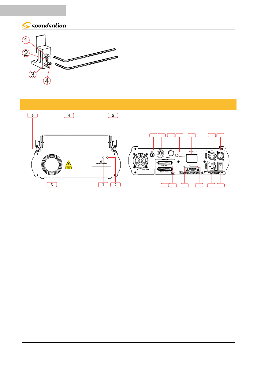
7. POLARIZED ADJUSTMENT
A laser equipment is an aggregate light that is affected by vibrations and other shocks
during transport and use. Due to these shocks, laser emitting mechanism might lose its
original alignment.
You can adjust the alignment through the three-dimensional adjusting frame as shown
in the picture.
Warning! Polarization adjustment can only be adjusted by qualied pro-
fessionals, operation, and to ensure strict accordance with the procedures
described in this manual.
11
7811181617
1312101915149
ENGLISH
8. FRONT/REAR PANELS
OMEGA-850 PRO
Professional Laser Show System
OMEGA-850 PRO User manual
NOTE:
• Adjust 1 and 2 at the same time
• Adjust 3 and 4 at the same time
INSTRUCTIONS
• 1 tight 2 loose - light slants to left
• 1 loose 2 close - light slants to right
• 3 tight 4 loose - light deflection moved up
• 3 loose 4 close - light deflection moved down
1. Power indicator LED: Red light when the device is turned on
2. Sound indicator LED: Music signal indicator
3. Laser output: Laser show; do not look directly into the hole (when laser scanning
pattern runs within ±1°, it will shut off laser automatically)
4. Handle: For carrying Laser Light during transportation
5. Hanging bracket: For hanging and angle adjustment
6. Insurance rings: Connecting wire rope to prevent illegal operation and fall
7. Power switch: Power ON/OFF.
8. Power Input: Power input socket, built-in fuse.
9. Key switch: Used to switch the machine off.
10. LCD display: User interface to control xture operation and settings.
11. SD-Card slot: Laser program storage and playback, compatible with TF, SD cards.
12. DMX output: 3PIN female XLR connector for DMX communication.
13. DMX input: 3PIN male XLR connector for DMX communication.
14. Adjustment keys: Adjustment of pattern size (5% -100% adjustment).
12

ENGLISH
OMEGA-850 pro User manual
15. Knob with push switch: Menu control knob up and down to select, push to con-
rm, exit, etc.
16. ILDA input: Standard ILDA interface, input, when connected to the device, it automatically switch between internal program and ILDA program.
17. ILDA output: Standard ILDA interface, the output signal gain unlimited coupling.
Playback control box as SD program output can be used as SD card-to-ILDA player
to other lasers with ILDA Interface.
18. Microphone: It Receives audio signal. Its response to the intensity can be adjusted
by SENSITIVITY potentiometer.
19. Remote Connector: By remoting this connector, you can place a safety ON/OFF
switch anywhere and use it for safety reasons to immediately switch Off laser
beam.
This unit has the ILDA DB25 interface and can be controlled by a PC. It automatically
converts ILDA laser show contents through the internal processing.
When connected to the 25-pin cable, the unit will be controlled by a computer or other
ILDA 25-pin standard equipment.
When no ILDA equipment are connected, the unit will play pre-programmed contents
from internal memory or SD-Card, and control other lasers with ILDA interface by mean
of THROUGH port.
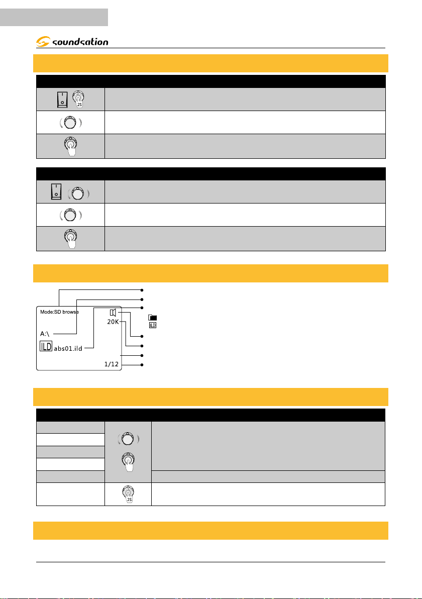
9. MENU OPERATING INSTRUCTION
When laser is powered on, rstly VERSION and MANUFACTURE INFORMATION will be
shown on LCD monitor. After a while it shows current operating standalone mode or
DMX address in case of DMX use.
With the help of the LCD display, it’s very easy to set and change operating mode. After
every resetting and saving, the new mode information will be shown on the LCD display
at next power on.
Turn left and right MENU encoder to move up and down or left and
right menu selections.
Press it to conrm the selection.
Press it 2 seconds, to jump out of current menu and go back to main
menu or return to the previous level.
13
Current operating mode
ENGLISH
9.1. Initial Setting
Language Setting
At start-up, when version information appears, press and hold 2
Choose between Simplified Chinese, Traditional Chinese, ENGLISH,
Confirm the selection, and automatically exit into boot routine.
At start-up, when version information appears, move left or right the
Choose between Color Setting, Maximum Scanner Speed, and Screen
Then select EXIT and press to confirm.
9.2. Display Interface Description
Current open folder name (A:\ directory in the SD card)
File type icon:
Graphic, file folder
ild format
Voice On indicator. It will appear only when open voice is on
Shows current scanner speed
Showis currently selected file or folder name
Shown total number of files in current directory and selected file number
OMEGA-850 PRO User manual
seconds.
and JAPANESE.
Basic Setting
encoder.
brightness setting
9.3. Play Function Description
Basic Setting
ILD show
PRG ILD List
Built-in show
Select 8 seconds after jump automatically to the selected
mode, or opt-out jumped into the selected mode.
DMX
Sound Active Sound control pattern change.
Exit Back to main menu and return to previous level.
9.4. Edit SD Playing List
In ILD mode, select the ILD document you want to edit, press inward (as below picture),
14

ENGLISH
OMEGA-850 pro User manual
le by le put into the SD list, as follows
ILD file playback times SD default list Select No. previously
compiled list will be added
to the back, empty on the
new list, re-start editing a
new list.
9.5. Pattern Setting
X mirror Horizontal direction of pattern ip
Y mirror Figure vertical direction ip
Color setting Single / Red Green Yellow / RGB
Scan Rate 0-20K, to choose scanner speed
Play speed
Pattern speed, the larger the numerical
value, the slower the playback speed
Compatible with
initial setting
Effective only in the
ILD play mode
10. DMX Channel Chart
Channel Value Description
000
001-040 ILD show in SD card
041-080 ILD show in SD card by sound control
CH1 MODE
081-100 PRG show in SD card
101-120 PRG show in SD card by sound control
121-160 AUTO SHOW
161-200 MUSIC SHOW
201-240 DMX MODE
241-255 DMX MODE by sound control
PRG or ILD MODE
Channel Value Description
CH2 000-255
CH3 Not working
CH4 000-255 Select the SD card folder
CH5 000-255 ILD file folder or play LST list
Laser Black Out
Sound sensitivity control
15

ENGLISH
DMX Programming Mode
Channel Value Description
CH2 000-255
001-049
CH3 / CH14
Pattern mode
selection
CH4 / CH15 Pat-
tern choose
CH5 / CH16
Shrinking
CH6 / CH17
Rotating
CH7 / CH18
Horizontal
CH8 / CH19
Vertical movement
CH9 / CH20
Horizontal shrink-
ing
CH10 / CH21
Vertical shrinking
CH11 / CH22
Gradually drawn
CH12 / CH23
Node
050-099
100-149
150-199
000-255
000-255 Total 256 patterns. Each value becomes into each pattern
000-063 Adjust the size of the pattern Manually
064-191
160-192 Shrinking
192-223 Enlarge
224-255 Zoom back and forth (largest to smallest)
000-063 Adjust the angle of rotation manually
064-191
192-223 Clockwise rotation
224-255 Counterclockwise rotation
000-063 Manually adjust the horizontal movement of Location
064-255
000-063 Manually adjust the horizontal shrinking movement of Location
064-255
000-063 Manually adjust the horizontal shrinking movement of Location
064-255
000-063 Manually adjust the horizontal shrinking movement of Location
064-255
000-063 Adjust gradually drawn position manually
064-255
000-255 The pattern node clarity adjusting
000
OMEGA-850 PRO User manual
Sound sensitivity control
Laser Blackout
Pattern out through the mode. Channel values of 1-6. The pattern
will shrink.
Pattern out of bounds fold back mode. Channel values of 51-56. The
pattern will be reduced.
Pattern out through the mode. Channel values of 101-106. The
pattern will shrink.
Pattern out of bounds foldback mode, Channel values of 151-156,
the pat-tern will shrink
The pattern out of bounds reentrant mode. Channel value 201-206
251-256 pattern will shrink.
Zoom back and forth • the 32th value as a section, into 3 section
effect
Rotating back and forth • the 32th value as a section. into 4 section
effect
The effect of vertical shrinking movement • the 32th value as a
section, into 6 section effect
The effect of vertical shrinking movement • the 32th value as a
section, movement
The effect of vertical shrinking movement ' the 32th value as a
section, shrinking
The effect of vertical shrinking movement • the 32th value as a
section, into 6 section effect
Adjust the speed of gradually drawn
16

OMEGA-850 pro User manual
000-007 Primary
008-015 Red
016-023 Green
024 031 Yellow
CH13 / CH24
Color
032-039 Blue
040-047 Purple
048-055 Cyan
056-063 White
064-127
128-191
192-255
Current discoloration
Monochrome transition
Blending transition
11. SPECIFICATIONS
Model OMEGA-850 PRO
Light source
Red 638nm 200mw
Green DPSS 532nm 150mw
Blue 450nm 500mw
Type Class 4 Laser
Zoom angle 1-36°
Speed 20K
External Control
I/O Connectors (DMX) 3-pin XLR / (ILDA) DB25
S/D Connectors Outlay SD card store programs
Channel Range 1-24
Internal Controller
Auto Two laser effects
Sound Two laser effects
Working condition
Maximum External Temp 104°F (40°C)
Cooling System Green TEC cooling
Power
Power Supply Type Switching (internal)
Range 100-240V 50/60Hz
Consumption 30W
Fuse T1.6A 250V
Mechanical
Dimension (LxHxD) 316 x 89 x 154 mm
Weight 4.26Kg
ENGLISH
17

ENGLISH
12. WARRANTY AND SERVICE
All SOUNDSATION products feature a limited two-year warranty. This two-year warranty is specic
to the date of purchase as shown on your purchase receipt.
The following cases/components are not covered from the above warranty:
• Any accessories supplied with the product
• Improper use
• Fault due to wear and tear
• Any modication of the product effected by the user or a third party
SOUNDSATION shall satisfy the warranty obligations by remedying any material or manufacturing
faults free of charge at SOUNDSATION’s discretion either by repair or by exchanging individual
parts or the entire appliance. Any defective parts removed from a product during the course of a
warranty claim shall become the property of SOUNDSATION.
While under warranty period, defective products may be returned to your local SOUNDSATION
dealer together with original proof of purchase. To avoid any damages in transit, please use the
original packaging if available. Alternatively you can send the product to SOUNDSATION SERVICE
CENTER – Via Enzo Ferrari , 10 – 62017 Porto Recanati - Italy . In order to send a product to service
center you need an RMA number. Shipping charges have to be covered by the owner of the product.
For further information please visit www.soundsationmusic.com
13. WARNING
PLEASE READ CAREFULLY – EU and EEA (Norway, Iceland and Liechtenstein) only
This symbol indicates that this product is not to be disposed of with your household waste, according to the WEEE Directive (2202/96/EC) and your national law.
This product should be handed over to a designated collection point, e.g., on an authorized onefor-one basis when you buy a new similar product or to an authorized collection site for recycling
waste electrical and electronic equipment (WEEE).
Improper handling of this type of waste could have a possible negative impact on the environment
and human health due to potentially hazardous substances that are generally associated with EEE.
At the same time, your cooperation in the correct disposal of this product will contribute to the
effective usage of natural resources.
For more information about where you can drop off your waste equipment for recycling, please
contact your local city ofce, waste authority, approved WEEE scheme or your household waste
disposal service.
18

This product is imported in EU by
Questo prodotto viene importato nella UE da
FRENEXPORT SPA – Via Enzo Ferrari, 10 - 62017 Porto Recanati - Italy
www.soundsationmusic.com
Soundsation® is a registered trademark of FRENEXPORT SPA - Italy
Soundsation® è un marchio di fabbrica registrato della FRENEXPORT SPA - Italy

www.soundsationmusic.com
Ver 1.1 - July 2017
 Loading...