


S O U N D P R O J E C T S
SOUND PROJECTS
Karperweg 16
1317 SN Almere
The Netherlands
Phone +31 (0)36 53 94 570
Fax +31 (0)36 53 00 578
G
G
EENNEERRAALL
I
I
NNFFO
O
AANND
D
O
O
PPEERRAATTIIOONN
M
M
AANNUUAAL
L
FFOOR
R
S
S
IIGGMMAA
S
S
EERRIIEES
S
™
™

Product info SPL Series
- 1 -
Contents
BASIC SET-UP PRINCIPLES ....................................................................................... 1
QUICK REFERENCE SET-UP GUIDE .......................................................................... 3
SPX MOUNTING BRACKET COMPONENTS .............................................................. 3
USING THE SPX MOUNTING BRACKET ................................................................... 4
SPX FLYING SYSTEM COMPONENTS ........................................................................ 5
5 SIMPLE STEPS TO RIG YOUR SPL ARRAY .............................................................. 7
SETUP EXAMPLES .................................................................................................... 9
GROUND-STACKING AN SPL ARRAY..................................................................... 10
GROUNDSTACKING ON TOP OF BASSBINS .......................................................... 12
ADDITIONAL SAFETY GUIDELINES ........................................................................ 13
MAINTENANCE ..................................................................................................... 13
SIGMA SERIES SPECIFICATIONS ............................................................................. 14
GUIDELINE TO MAXIMUM AMOUNT OF CABINETS .............................................. 15
DECLARATION OF CONFORMITY ......................................................................... 16
All the important notes regarding proper operation of the product and potential danger
or damage to either the user or the equipment, are highlighted in light grey

Product info SPX Series
- 1 -
Basic set-up principles
The SPL90, SPL90T, SP2-10 and SP18 are components of the Sigma Series modular, selfpowered, audio system. Many combinations of the top cabinets with SP2-10 and SP18 are
feasible. All models have integrated rigging points enabling each system to be flown by means
of pragmatic rigging hardware.
The SPL housing, originally a conventional stack design, is easily converted into a so called
virtual line array. Benefits achieved by flying multiple SPL systems opposed to stacking side by
side are achieved through minimizing overlap areas.
The hybrid design greatly enlarges functionality of the system. The trapezoidal housing of the
SPL90-T adds the advantage of a rotatable horn enabling rigging without an open splay at the
fronts of the cabinet.
Establishing proper vertical coverage of a line-array
The first step in the configuration process is to get the venue parameters and listeners positions
right. It may seem logical but a good preparation is the main time-saver in setting up any audiosystem. Once these parameters, such as distances to first and last listener positions and flying
height, are known prediction software such as SPArC™ can easily be employed to configure the
best flying position.
Establishing proper height of the rig
In general, flying a system higher will bring a more even loudness throughout the audience, and
flying at a lower position will get more loudness at the front listener positions. The highest horn
unit in the SPL array should be aimed at the furthest listening position. In many cases it might
even be preferred to aim just a little above this position.
When a line array is flown it is most logical to configure from top to bottom (far coverage to
near coverage). Therefore it might not always be possible to point the bottom array element to
the nearest listener position to be fed by the array (e.g. due to limited number of array elements).
Additional front fill is then necessary. Another situation where front fill is preferred is when the
array is flying relatively high to the first listeners position. In order to avoid 'elevator-music'
coming from above, front fills placed at stage height will place the sound image downward for
the front of the audience.
When a line array is ground stacked it is more logic to configure the array from bottom to top.
Additional front fill can still be used, however often not necessary.
Horizontal coverage
In some cases it might be necessary to use more than one array per side in order to achieve
more horizontal coverage or to be used as in-fills. An important rule applies when this situation
occurs. Instead of placing an array directly besides the first one a more suitable approach would
be to utilize a second array, which is focused on another portion of the audience and spaced at
least 6-7 meters (approximately 20 ft) away from the first array.
Given this separation, interference only occurs in the low frequency range and there are no
audible intelligibility losses for two reasons: the first main cancellation is shifted lower in
frequency (example, 28 Hz for 2 arrays of the same size, spaced 6 metres) and tends to be
masked or filled in by room reverberation; by focussing the arrays at different panning angles,
comb filtering interaction is lessened since their overlap region is reduced. In addition, the ear
cannot resolve tightly spaced comb filtering notches at higher frequencies throughout the
overlap region.

Product info SPX Series
- 2 -
Typical stack configuration consisting of 1xSPL90T, 1xSP2-10 and 2xSP18s

Product info SPX Series
- 3 -
Quick reference set-up guide
Carefully read this section before suspending the SPL system
Note! The SPX flying system has been designed according to most international
guidelines for overhead suspension. However, local safety legislation may be
applicable and it is the responsibility of the installer to apply these safety guidelines.
SPX Mounting bracket components
SPX Mounting Bracket
For single or double* cabinet fixing
*restrictions apply
Quick Release Pin
Bracket and connector fixes
4 pins per bracket included
SPX Connector set
Cabinet interconnection
2 per cabinet
8 Quick Release Pins included

Product info SPL Series
- 4 -
Using the SPX Mounting Bracket
The SPL mounting bracket is designed for use with a single cabinet when using the middle
fixing hole or 2 cabinets when using the two outer fixing holes.
All items for cabinet fixture are included. Various ways to connect the bracket to wall, ceiling or
construction are applicable. Items for this purpose are optional.
Step 1
When using a clamp or other device
connect the clamp to the bracket. Connect
safety slings to the left and right hole on top
of the bracket if deemed necessary.
Step 2
Once the mounting bracket is prepared for
its intended purpose, the cabinet may be
fixed to the bracket using the Quick Release
Pins. There are three angles possible:
parallel to bracket or tilted 10 or 15 degrees
downwards.
Step 3
ONLY applicable when using the two
outer fixing holes of the Mounting
Bracket!
Connect a second cabinet by means of two
connector plates and 8 quick release pins.
Safety Note: For direct fixes to walls or ceilings ALWAYS use two or more fixtures (e.g.
safety slings) suitable for the applicable underground! Consult local rigging legislation
regarding overhead suspension.

Product info SPL Series
- 5 -
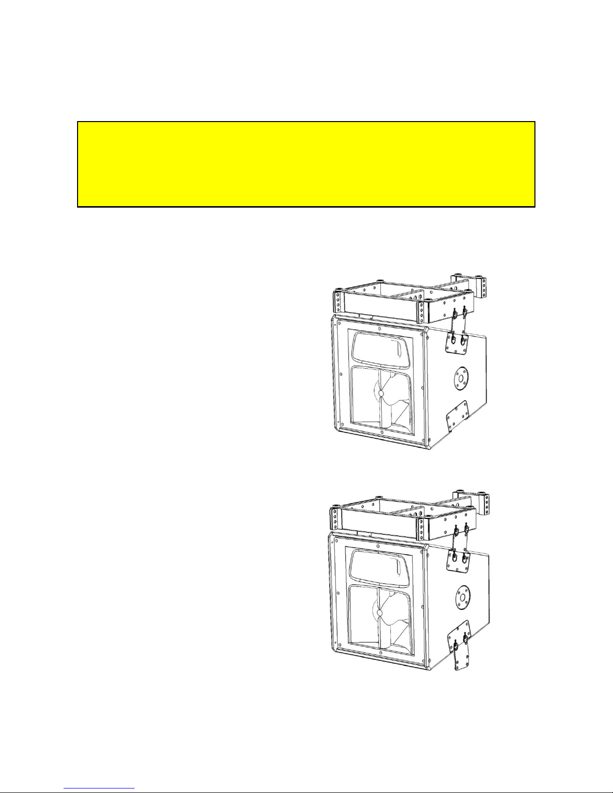
SPX flying system components
SPX Basic Flyingframe
for use up to 6 cabinets
SPX Flying frame Extender
For use up to 6 cabinets –
configuration dependant
SPX Flying frame assembly
for flying up to 6 cabinets or groundstacking up to 4 cabinets
for flying below or on top of SP18/SP2-10 bassbins
Flying frame and extender are connecter by means of bolt M12x60, washers and locking nuts
M12 (included)
Product info SPL Series
- 6 -
Consult the Guideline to maximum amount of cabinets on page 15 when preparing the
design of an SPX line-array using the SPX flying frame with the flying frame extender.
Quick Release Pin (8 per cabinet)
Connector fixes
SPL Connector (2 per cabinet)
Cabinet interconnection
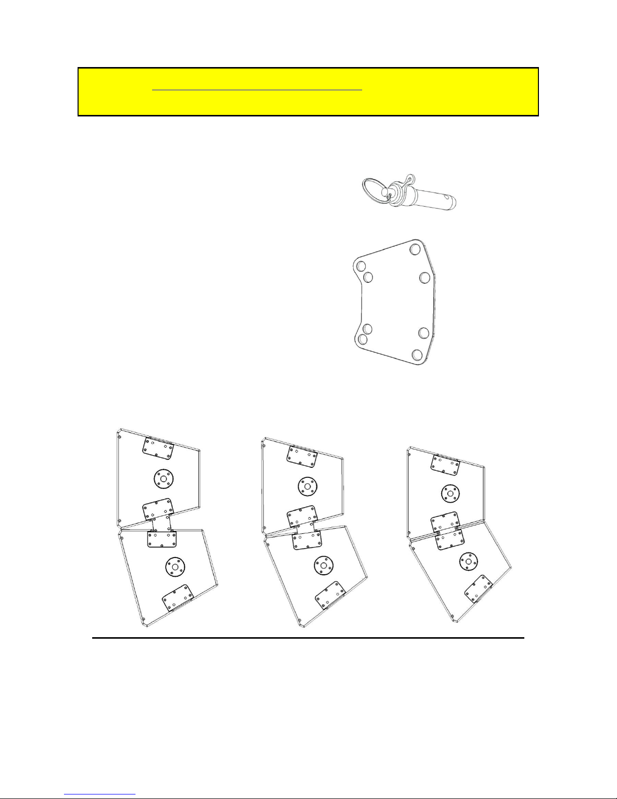
Angle settings of the SPL connector
The SPL connector holds 4 pairs of holes enabling combinations for 3 different angle settings:
15, 22.5 or 30 degrees between cabinets.
The 3 combinations of the SPL connector resulting in 15, 22.5 and 30 degrees respectively
Combining the outer two pairs results in a 15 degree angle.
One outer pair and one inner pair results in 22.5 degrees.
Combining the two inner pairs gives a 30 degree splay.
Product info SPL Series
- 7 -
5 simple steps to rig your SPL array
Safety Note:
The maximum amount of cabinets to be hoisted by the SPL flying frame is dependent
on the configuration of the intended setup. Due to momentum critical forces on
connectors will increase fast when the lifting point is shifted backwards. Consult table
on page 15 to avoid overload situations!
Method A
Step 1
When using the Flying frame extender, start
with assembling the extender to the flying
frame. Then connect the flying frame to the
first cabinet in line with the connectors and
Quick Release Pins and attach the hoist at
the corresponding hole.
When flying below subcabinets the flying
frame needs to be attached to the
subcabinets first.
Step 2
Lift the frame and cabinet to approximately
head-high position to enable attachment of
the next cabinet. Start with attaching the
two connectors at the cabinet in the array
using the Quick Release Pins.

Product info SPL Series
- 8 -
Step 3
Now lift the adjacent cabinet with one
person a side and attach it to the extending
connectors using two QRPs per side.
Step 4
Connect audio and mains power cables.
Repeat step 2 thru 4 for all cabinets in the
array.
Step 5
Connect audio and power cables and lift
the SPL array to the desired height.
Guide the cables and fix them to avoid
extensive pulling forces at the connectors.
Method B
See chapter ‘Ground-stacking an SPL array’
to comfortably fly small arrays without
subcabinets. In step 3 the complete cluster
is lifter by a motorhoist instead of tilted
upright.

Product info SPL Series
- 9 -
Setup examples
Typical system setup consisting of 2 SPL90-Ts, 2 SP210s and 4 SP18s

Product info SPL Series
- 10 -
Ground-stacking an SPL array
Note: Always use an SPX flying frame with extender to stack an array of SPL cabinets.
When stacking on top of a cluster of bassbins it is highly recommended to secure the
flying frame with connectors to the bassbin.
Up to 4 cabinets can be groundstacked by means of the SPX flying frame with extender. Setup
can be done either by placing cabinets one by one on top of each other or by pre-assembling
the array on the floor and tipping the complete cluster including frame. The latter is explained
below.
Step 1
Pre-assembly the array of cabinets on the floor with the angles between cabinets as needed.
Step 2
Attach the flying frame including extender at the intended angel with the rubber feet pointed
outwards.

Product info SPL Series
- 11 -
Step 3
Lift the complete ground stack array in an upright position.
Typical groundstack setup consisting of 3 SPL-90Ts on a flying frame.
Note: the maximum amount of cabinets is largely depending on local circumstances
such as ground-stability, weather influences (e.g. wind) and array shape. Always check
groundstack stability physically and if necessary grant stability using stabilizing lines.

Product info SPL Series
- 12 -
Groundstacking on top of Bassbins
When making a ground stack on top of a bassbin cluster it is highly recommended to use fixing
connectors between the bassbin and the SPL flying frame.
Example Groundstack setup consisting of 4 SPL-90Ts and 2 SP18s

Product info SPL Series
- 13 -
Additional Safety Guidelines
Before suspending the SPL system be sure you apply the following general safety guidelines.
Standards for flying and rigging are local not universal, therefore it is important for the user
to contact appropriate regulatory agencies concerning relevant standards for specific
applications.
Before suspending any system, always inspect all components of the rigging system for
deformation, corrosion, and damaged or missing parts that could reduce strength and safety
of the rigging system.
Use only load rated hardware.
Never exceed maximum load ratings at any time.
Consult a licensed physical engineer if you are unsure how to proceed.
It is advisable to consult and engage a qualified rigger when making decisions related to
purchase, set-up and use of any equipment and technique that will be used to suspend any
temporary loudspeaker system above areas that will be occupied by persons.
Never tilt the array by pushing or pulling the array at the enclosures itself! The flyingframe is
equipped and designed to be used both as lifting point and tilting point.
Maintenance
Minimum requirements for inspection of flying hardware:
Control all rigging hardware on deformations, irregularities and missing or loose parts before
every use. (User)
Inspect all items at least once a year. (Qualified rigging personnel)
Approval testing by Certified Body every two years. (Official agency)
Like any high performance tool your Sound Projects system needs regular maintenance.
Check all bolts and nuts of your audio systems at least once a year!
Clean fan-grill, foam-grill and cabinet openings with vacuum cleaner and compressed
air to remove excessive dust. Frequency depending on local circumstances.

Product info SPL Series
- 14 -
Sigma Series specifications
Model:
SPL-90(T)
SP2-10
SP18
Acoustical
specifications:
Max. peak SPL @1m:
crest factor 2 (6 dB)
136dB
136dB
132dB
Freq. response:
250 Hz -20kHz
60 -250Hz
25 -60/250Hz
Coverage angle:
85H x 30V
omni-directional
omni-directional
Electrical
specifications:
- Drivers:
10”/ 1.4”
2 x 10”
18”
Transient output:
1000W
1000W
1000W
Amplifier(s):
MA1000™ technology
Protection:
D.A.L.C. (Double AudioLogic Control)
Fast double driver-relais turn on/off
Transient (soft power-up)
DC-voltage short-circuit
LED indication:
power-on/signal/protect
Input impedance:
20 kOhms balanced,
10 kOhms unbalanced
Output impedance:
hard-wired to input
Protection threshold:
+4dBU
Mains voltage:
230V (other on request)
Mains frequency:
50/60 Hz
Power cons. Idle:
< 50VA
Additional data:
Cabinet
construction:
crossgrain laminated multiplex
Finish:
Nano Armor PU Coating
Size WxHxD (mm):
395x600x405 trapezoid
Rigging points:
integrated SPX flypoints
recessed pole-mount adapter
Audio connectors:
IEC XLR-3 in/out
Main connectors:
powercon in, powercon out
Max. operating
temp.:
-10 to 40 C ambient
Weight:
32kg
58kg
54kg
Additional information about SPL Series can be found on our website: www.soundprojects.com

Product info SPL Series
- 15 -
Guideline to maximum amount of cabinets
*Flying frame should be positioned horizontally
ALWAYS consult Sound Projects’ proprietary acoustic prediction software SPArC™
(downloadable at www.soundprojects.com) to determine the maximum amount of
cabinets at specific situations. The angle of the flying frame influences the forces on the
flying hardware.
Note: The maximum amount of cabinet as described in the table above are calculated
with double the design factor as described in the ‘Guidelines for Machinery’ making it
suitable for overhead suspension in most European communities. (e.g. NPR 8020)
M
M
OODDEEL
L
M
M
AAXXIIMMUUMM NNUUMMBBEERR OOFF CCAABBIINNEETTSS
**
SSPPXX
66 66 66 55 44 44 44 SSPPLL 66 66 66 66 55 44 44
SPX
SPL

Product info SPL Series
- 16 -
Declaration of Conformity
Almere, 1 October 2010
D
D
EECCLLAARRAATTIIOONN OOFF CCOONNFFOORRMMIITTY
Y
SOUND PROJECTS, hereafter referred to as the manufacturer, declares that the SPX rigging
system and its rigging hardware as supplied by the manufacturer are produced and, when
provided with certificate, tested conform CE norms as described in the Guidelines for Machinery
appendix 2A.
SOUND PROJECTS
Karperweg 16
1317 SN Almere
The Netherlands
 Loading...