

Page 1
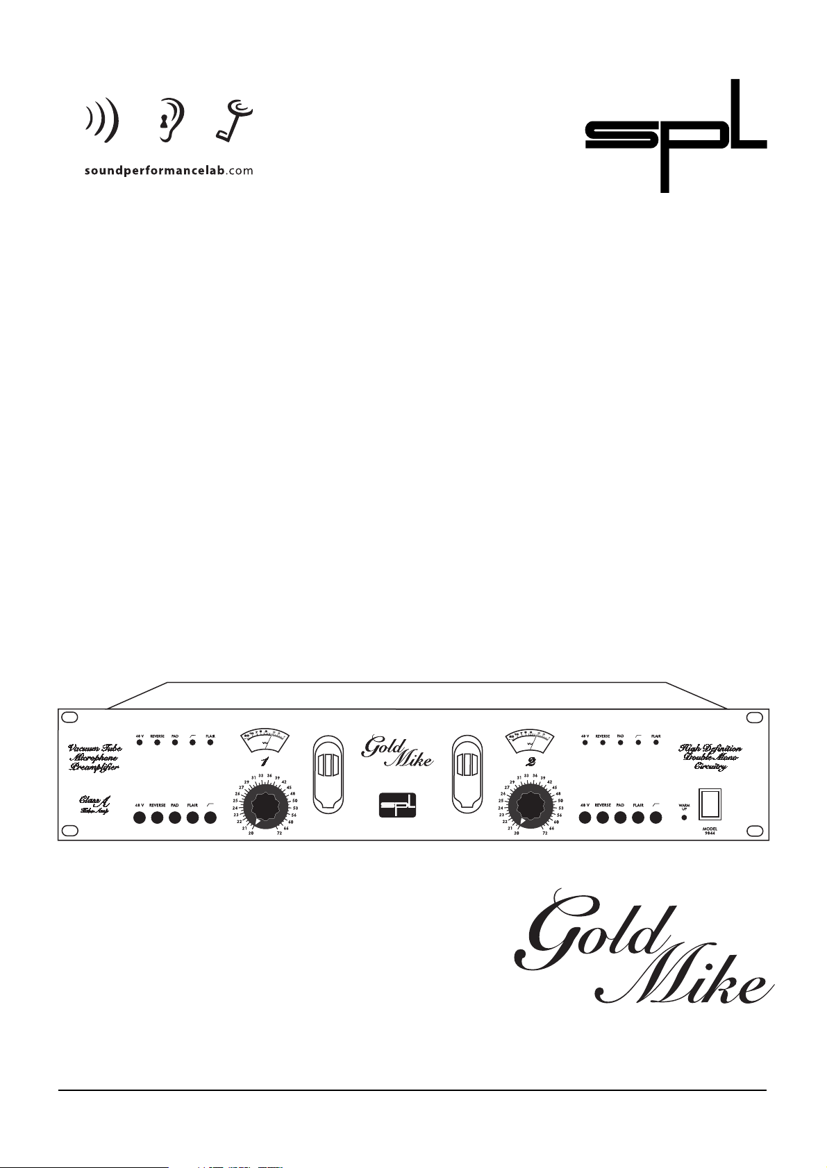
Model 9844
Manual
Vacuum T ube Microphone Preamplifier
Page 2

By Hermann Gier and W olf gang Aichholz
Version 1.4 - 5/2000
The information in this document has been
carefully verified and is assumed to be
correct. However Sound Performance Lab
(SPL) reserves the right to modify the product
described in this manual at any time.Changes
without notice.This document is the property
of SPL and may not be copied or reproduced
in any manner, in part or full without the
authorisation of SPL.
Limitations of Liability:
In no event will SPL be liable for any damages,
including loss of data, lost profits, cost of
cover or other special,incidental,consequential or indirect damages arising from the use
of the unit, however caused and on any
theory of liability. This limitation will apply
even if SPL or an authorised dealer has been
advised of the possibility of such damage.
SPL electronics GmbH
P.O.Box 12 27
D- 41368 Niederkruechten,Germany
Phone +49 - 21 63 / 98 34-0
Fax +49 - 21 63 / 98 34-20
eMail:info@ soundperformancelab.com
GoldMike
Model 9844
Manual
© 2000 SPL electronics GmbH. All rights reserved.
Page 3

3
Contents
Foreword .................................................................................................. 3
Introduction ............................................................................................ 4
Hookup ..................................................................................................... 5
Installation & Connections ................................................................. 5
Power Supply ............................................................................................ 6
Tech Talk .................................................................................................. 7
Control elements ................................................................................. 9
MIC GAIN............................................................................................. 9
48V ....................................................................................................... 9
REVERSE ..............................................................................................10
PAD ....................................................................................................... 10
HIGHPASS ...........................................................................................11
FLAIR ....................................................................................................11
Displays ...............................................................................................11
Specifications .........................................................................................12
Warranty ...................................................................................................13
Foreword
Thanks
I would like to start with my thanks to all our staff,who created
what is to be described here.The importance of their exceptional
qualification and talents cannot be overestimated.Special thanks
to Ruben Tilgner for his creativity.
Our products are often tested and compared in many publications and by our customers themselfs and constantly valued with
best results. I would like to pass on this broad appreciation to
those,who deserve it – my excellent colleagues .
Hermann Gier
Dear customer,
Thank you for the confidence you have shown towards
SPL electronics GmbH by purchasing the SPL GoldMike.You have
decided to use an innovative microphone preamp which
provides excellent sound quality by combining exemplary specifications with highest manufacturing standards. Please read this
manual carefully to ensure you have all the information you need
to use the Gold Mike.We wish you every success with it.
Your Sound Performance Lab-Team
Page 4

4
The GoldMike is another jewel in the SPL Tube series.Like all SPL
tube processors,the G oldM ike combines the unique sonic qualities
of tube technology with state-of-the-art manufacturing, meticulous component selection and high-tech conception.
This latest product,a dual-channel tube microphone preamplifier
with superb sonic qualities, is particularly suited for recording
vocals and acoustic instruments. You will be surprised by not
only its precision but also the natural impact of different vocal
timbres – the silky warmth of a pristine tube sound is needed by
more than just acoustic guitars!
You don't have to listen to those dead and sterile HD recordings.
GoldMike's whisper quiet performance makes it ideal for digital
recording.Even the most demanding recording subjects,such as
a choir,are easily handled. The Class A tube amp, designed as
two independent mono blocks, guarantees absolute channel
separation.Your stereo recordings in particular will benefit from
a wider stereo depth.
GoldMike's technical standards are predicated on an uncompromising effort to combine the sonic advantages of tubes with the
experience of more than 12 years of research in semi-conductor
amplification design.
The GoldMike allows for up to 72 dB of gain – a value tube-only
designed preamps can't match.The SPL tube/IC construction,
on the other hand, superbly combines today's standards with
such trademark tube characteristics: improved spatial depth,
rich detailed imaging, warm and smooth sonics. Moreover, the
GoldMike delivers high common-mode-rejection and ultra linear
amplification in addition to the high gain capabilities.
Features
• Unique "FLAIR" circuitry enhances the presence and
intelligibility of any signal.Vocals,for example,
seem to move closer.Pristine,non-colored "softening"
of very harsh and aggressive sounds
• 50Hz high-pass filter
• Phase reverse switch
• 30dB pad
• Switchable 48-volt phantom power with
independently filtered power supply
• High-qualit y ALPS potentiometers
• Click-free switches
• Five LEDs per channel
• Two backlit VU meters
• Warm-up LED indicates tube status during warm up
• Star ground wiring scheme for best sound performance;
extra wide PCB ground connections guarantee
stable voltage distribution
• Power supply with state-of-the-art filtering schemes and
solid power reserves (6000 µF in the main supply
and 400 µF in the tube supply)
• XLR inputs
• XLR and 1/4" outputs (c an be used individually or
simultaneously)
Introduction
Page 5

5
Carefully select a place for setting up the GoldMike. The unit
should be situated away from heat sources and direct sunlight.
Avoid installing your GoldMike in environments exposed to vibrations,dust,heat,cold or moisture.Keep the unit away from transformers or motors or any other unit that could generate large
variations in power supply or cause electrical interferences. Do
not install the unit in close proximity to power amplifiers or
digital processors.You may consider placing it in a rack containing other analog gear.Such placement can prevent interference
from Word Clock,Smpte,MIDI,etc.
• Do not open the case. You may risk electric shock and may
damage your equipment.
• Leave repairs and maintenance to a qualified service technician.
Should foreign objects fall inside the case,contact your authorised
dealer or support person.
• To avoid electric shock or fire hazards do not expose your unit to
rain or dampness.
• In case of lightning unplug the unit.Please unplug the cable by
pulling on the plug only;never pull on the cable.
• Never force a switch or knob.
• To clean the case use a lint-free cloth. Avoid cleaning agents as
they may damage the chassis.Manufactured in standard 19" EIA
format,it utilises two rack units.
• Please support the back of the unit whenever it is being mounted
into a 19" rack (especially important when touring).
Again, while GoldMike's housing is EMV-proof and protects
against HF-interference, placement of the unit is ver y important
since it is capable of amplifying microphone signals as well as
other unwanted signals up to 2200 times.Before connecting the
GoldMike, or any other equipment, turn off all power. Adjust the
voltage setting on the back so that it corresponds with the power
conditions.The GoldMike's XLR inputs,which are used for connecting microphone and line level signals, are electronically
balanced, while the outputs allow for simultaneous feed to the
balanced XLR connectors as well as to the unbalanced 1/4"
outputs.The unit can even be used as a microphone splitter .
Important safety instructions--
please read carefully!
Hookup
Installation &
Connections
Page 6

6
The following graph shows the correct wiring for connecting unbalanced signals to the balanced XLR connectors.
VERY IMPORTANT
Phantom power must be switched off before unbalanced signals
are connected! Otherwise short circuits cause damages!
Built around a torroidal transformer ,the power supply allows for a
minimal electromagnetic field with no hum or mechanical noise.
The supply voltage can be set to 230 V/50 Hz or 115 V/60 Hz.
Check your country's power requirements for the appropriate
setting. An AC power cord is included to feed the IEC-spec, 3prong connector. Transformer, AC cord and IEC-receptacle are
VDE, UL and CSA approved. The main fuses are rated at 315mA
(230V) and 500mA (115V).
Chassis ground and AC ground can be physically disconnected
by the “Ground Lift” switch (GND LIFT). This helps to eliminate
hums.The power supply's output side is filtered by an RC circuit to
extract noise and hums caused by your power service. 6000µf
capacitors smooth out the positive and negative half waves.
The phantom power is derived from a separate winding in the
transformer.Filtered and rectified by a series of zener diodes and
transistors,a clean 48 volts leaves the circuitry.This supply voltage
reaches the phantom power switch through the PCB where
another RC circuit stabilises the supply again. Our high quality
0.1%/6,81kOhm resistors ensure the pristine quality of the
phantom power supply .
A stable,low ripple torroidal power
supply is the foundation for any
high-fidelity sound shaping.
The GND-LIFT switch helps
eliminate hums caused by
ground loops.
Phantom Power with a complex
filtering scheme and highly
selected components.
Power Supply
Page 7

7
Advantages of the SPL dual-stage preamplifier
The GoldMike's engine is the newly designed SPL dual-stage
preamplifier.During the first stage of amplification the signal is
amplified by a semi-conductor circuit while the second stage
applies tube electronics.We achieve a high common-mode-rejection by using laser trimmed components.Likewise,minimal noise
and distortion figures distinguish our high-quality preamp.
Analog Device's semi-conductor (SSM2017) is very unreceptive to
HF and hum interference,and is perfec tly integrated by the PCB
layout; wide PCB conductors guarantee a stable power supply
even when extreme level changes demand an immediate current
supply. The star ground wiring scheme ensures a quiet elec tronic
performance. The dimensions of the PCB conductors, and their
respective layout (wide or narrow),were especially designed for
the integration of tubes and ICs in the preamplification circuitry.
The MIC GAIN potentiometer adjusts the semi-conductor stage,
allowing amplification up to 2200 times the original signal. The
following secondary tube stage adds a constant 6 dB of gain;
therefore,the same amount of tube character is added regardless
of amplification. The MIC GAIN should be adjusted for a "0" VU
meter reading.At this level the best signal-to-noise performance
is achieved and the tube will perform in its ideal sonic range.
(Please note that the VU readings are not peak PPM but average
levels.In other words,watch out for the meter hitting the red.)
In summary,our dual-stage design maximises the amplific ation
power and signal-to-noise performance of the SPL semiconductor at the first stage and then maximises the warmth and
liveliness of a meticulously selected and tested ECC 83 tube at the
second stage.This makes the GoldMik e an ideal par tner for highend HD recording. The unit's dynamic range of 111 dBu even
outperforms some 24-bit recording gear.
Advantages of the dual mono design
GoldMike's two mono amplifier blocks are designed with a
central power supply that utilises a star ground wiring scheme.
Chief advantages of this particular layout are the excellent
channel separation and,respectively,the low crosstalk figures.
In your daily work you will find many practical applications for
these advantages. You may use the GoldMike's channels for a
snare and a vocal (arguably the most important elements in a
mix) simultaneously. Stereo recordings, benefiting in particular
from the low crosstalk figures,will have wider stereo depth and
precise spatial definition.Another advantage of the central power
supply with a star ground wiring scheme is that the two individual circuitries, operating discretely, can deliver identical sonic
performances per channel.The current demands of one channel
(i.e.,snare) are not compromised by the current demands of the
other channel (i.e.,vocal). All power supplying conductors, layed
out identically and symmetrically,provide both channels with the
necessary current.
Tech Talk
The GoldMike combines superb
signal-to-noise specs with not only
the amplification power of semi-
conductors but also the warmth
and liveliness of tubes.
An outstanding dynamic range of
111 dBu outperforms even the
average 24-bit recording system.
Dual-Mono-Layout, with central
power supply and star grounding,
delivers excellent
channel separation
• two discrete signals (snare,vocal)
may be recorded simultaneously
without crosstalk
• precise spatial definition
• identical sonic performance
per channel
Page 8

8
Sound optimization already during recording:
FLAIR circuitry
The FLAIR circuitry enhances the presence of vocals and acoustic
instruments, FLAIR makes these elements cut better through a
mix. It has proved to be superior in double-blind tests. Once a
signal completes the semi-conductor amplification stage, it is
then split and fed into the tube stage and the FLAIR electronics.
The FLAIR circuit is built from a unique valve/inductor/capacitor
hybrid.I t operates in a bandpassed frequency range from 1.5 kHz
to 20 kHz.The center frequency is set at 6 kHz with a boost of 2.5
dB. Frequency response, harmonic contents and time of impact
are manipulated as well. The FLAIR circuit's output is mixed
directly in the tube with the source signal.The circuit's character
can be best described as a "closed shelving bandpass";nevertheless, a shifted timebase (phase) is responsible for boosting the
harmonic content. The close correlation, however, between
frequency- and amplitude-timebase to the dynamics of the input
signal remains intact.
When working on a hard disc recording system,you will greatly
appreciate the appeal of the Flair circuitry and the topnotch
sounding signal it delivers. I t can spare you hours of twiddling
with a compromised recording.
WARM UP circuit
The W ARM UPcircuit measures the tube's anode plate and heater
voltages. After approximately eight seconds the anode voltage of
250 Volts is reached; the heater voltage takes only four seconds.
Once the ideal working status is achieved, the output signal is
enabled.As the W ARM UP LED is lit,no output is present.
Tech Talk
The FLAIR circuitry
enhances a signal's presence
and cutting ability.
The correlation between
frequency- and amplitude-timebase to the dynamics of the input
signal remains intact.
Ideally suited for HD recording.
Page 9

9
Control elements
The MIC GAIN knob controls the input signal's amplification.The
range extends to 72 dB of gain.The levels should be adjusted for a
meter reading around 0 VU to get the best signal-to-noise performance. Please note that the meters show only an rms/average
level, so keep your GoldM ike from pegging the meters' needles.
When adjusting the MIC GAIN, consider the t ype of microphone
(dynamic,condenser or ribbon) and the microphone's sensitivity;
likewise, check sound pressure levels at the sound source, the
microphone placement and room acoustics.The sensitivity of a
dynamic microphone is approximately 2 mV/Pa, whereas a
condenser microphone may reach 20 mV/Pa,an increase of 20 dB.
Condenser Mics require a 48-volt power supply, which is sent
through the balanced audio cable on pins 2 and 3.When tur ning
on the supply voltage,a phantom circuit is generated by splitting
the 48-volt supply signal equally between the + and - conductors
of the audio cabling; the voltage is returned through the cable's
shield. No potential difference is present between the two
conductors (+/-); dynamic microphones may be used while
phantom power is switched on without damage.
Phantom power in effect reduces the interference from ground
loops as well as other unwanted signals picked up by the shielding.It also proves to be a very HF resilient connection.
WARNING: All balanced microphones with isolated
grounds, even tube-equipped microphones, may be used
while phantom power is switched on. All other microphones
require the phantom power to be switched off.
Connect line-level signals and unbalanced microphones
only while phantom power is off.
7
2
3
4
5
6
MIC GAIN
1
48 V
2
Phantom power specs in
accordance with
DIN 45 596/ IEC 268-15
1
The VU meters show
a rms/average signal
Check the transducer type and
sensitivity
!
Page 10

10
HIGHPASS
5
Filters problematic frequen-
cies (rumble,etc.)
Tips on how to use the phase
reverse
30 dB pad
By pressing the REVERSE button, you invert the microphone's
polarity.When the REVERSE button is released (status LED off) the
signal is in phase. Pressing it switches the signal out-of-phase
(LED on).
Reasons for reversing the phase:
1.You are recording a vocal or voice-over and the vocalist cannot
hear him or herself very well in the headphones. Reversing the
phase effectively reverses the polarity between microphone and
monitor signal, thus enabling the vocalist to hear him or herself
better without any volume increase in the headphones.
2.The REVERSE button is engaged to adjust the GoldMike to the
polarity of a microphone or microphone wiring scheme.
GoldMike's XLR connectors are configured as follows: pin 2 =
high (+),pin 3 = low (-).
3.Experimenting with the phase reverse option may reward you
with better results.
The PAD switch attenuates the input signal by 30 dB, allowing
even high-level signals to be processed by the GoldMike.This may
apply to loud drum or brass recordings.
The HIGHPASS filter will pass only frequencies above a certain
threshold,thereby eliminating unwanted portions of a signal.The
GoldMike's roll-off point is set to 50 Hz. We use a 2nd order
Butterworth filter for its low ripple.The roll-off slope is 12 dB per
octave.
Applications for the HIGHPASS filter:
1.Voice-over recordings suffering from the "proximity effect",a
boost in low frequencies due to the short distance between sound
source and microphone.
2."Pop" sounds that extend into the lower frequency range.
3. Any unwanted signal, such as steps,rumble and other low-frequency sounds.
REVERSE
3
PAD
4
Page 11

11
True to SPL's philosophy,the GoldMike features the sound enhancing FLAIR circuitry.More than simply a frequency-range manipulating tool, the FLAIR circuitr y is also a timebase shifting (phase)
device that enhances a sound's harmonic content.The close relation between frequency- and amplitude-timebase and the source
signal's dynamics remains intact.
FLAIR boosts the frequency range from 1.5 kHz to 20 kHz.The
center frequency, set at 6 kHz, is boosted 2.5 dB and applied
mainly to the harmonic content and format frequencies of voices
and acoustic instruments.And finally,the FLAIR's output is mixed
right along with the original source signal by the tube during the
tube amplification stage.
The resulting recorded signal resounds with more detail,intelligibility,presence and cut- through.The FLAIR circuitry is especially valuable when working in an HD recording environment
because of the great sounding signal it delivers at the outset,
thereby sparing you hours of fixing a compromised recording.
Each of the GoldMike's channels is equipped with a backlit VU
meter (calibrated to 0 dBu) that displays the unit's output level.
Five LEDs per channel display the current operating status.
The WARM UP LED,located next to the power switch,remains lit
until the unit's tubes reach their optimum operating condition.As
long as the WARM UP LED is lit,no output is available.
FLAIR
6
DISPLAYS
7
Circuitry enhances presence and
boosts cut-through
Manipulates frequency range,time
impact and harmonic content
simultaneously
Page 12

12
Audio
Frequency Response:...................................... 10 Hz - 100 kHz,+/- 0.5 dB
Common-Mode-Rejection at -20 dBu:...... 1 kHz:-80 dBu
... 10 kHz:-73 dBu
Harmonic Distortion
Input level Gain THD
-30 dB ................................... 30 dB ................... 0.175 %
-60 dB ................................... 60 dB ................... 0.2 %
Signal-To-Noise Ratio
Signal-to -Noise ratio: Gain A-weighted
72 dBu -62.4 dBu
60 dBu -71.8 dBu
30 dBu -85.6 dBu
Dynamic Range: ............................................... 111 dBu
Noise Figure:...................................................... 3.8
E.I.N.(Equivalent Input Noise) ..................... 135.4 dBu
Inputs
Microphone/Instrument Preamplifier ,
electronically balanced (differential),transformerless
Input Impedance ............................................. 1.8 kOhm
Max.Input Level ............................................... +25.72 dBu
Outputs
XLR-Output:Microphone/Instrument Preamplifier,
electronically balanced (differential),transformerless
Nominal Output Level XLR .......................... +6 dB
Max.Output Level XLR ................................... +25.4 dB
Nominal Output Level 1/4" .......................... 0 dB
Max.Output Level 1/4".................................. +19.4 dB
Output Impedance (XLR/Klinke) ................ < 600 Ohm
Dimensions
Standard EIA 19"/1HE chassis ...................... 19" x 3.47" x 6.18"
(482 x 88 x 157mm)
Weight ................................................................. 6.7 lbs.(3.05 kg)
Rear Panel Controls and Connectors
• Balanced Inputs and Outputs (XLR/+6 dB)
• Unbalanced Outputs (1/4" / 0 dB)
• V oltage Selector 115 V/60 Hz or 220 V/50
• 3-Prong Standard-IEC-AC Receptacle
• GND-LIFT-Switch
Specifications
GoldMike Rear Panel,Model 9844
Page 13

13
Warranty
SPL electronics GmbH (hereafter called SPL) products are
warranted only in the country where purchased, through the
authorized SPL distributor in that country, against defects in
material or workmanship. The specific period of this limited
warranty shall be that which is described to the original retail
purchaser by the authorized SPL dealer or distributor at the time
of purchase.
SPL does not, however, warrant its products against any and all
defects:
1) arising out of materials or workmanship not provided or
furnished by SPL,or
2) resulting from abnormal use of the product or use in violation
of instructions,or
3) in products repaired or serviced by other than authorized SPL
repair facilities,or
4) in products with removed or defaced serial numbers,or
5) in components or parts or products expressly warranted by
another manufacturer.
SPL agrees, through the applicable authorized distributor, to
repair or replace defects covered by this limited warranty with
parts or products of original or improved design, at its option in
each respect,if the defective product is shipped prior to the end
of the warranty period to the designated authorized SPL warranty
repair facility in the country where purchased, or to the SPL
factory in Germany, in the original packaging or a replacement
supplied by SPL, with all transportation costs and full insurance
paid each way by the purchaser or owner.
All remedies and the measure of damages are limited to the
above services. It is possible that economic loss or injury to
person or property may result from the failure of the product;
however, even if SPL has been advised of this possibility, this
limited warranty does not cover any such consequential or incidental damages.Some states or countries do not allow the limitations or exclusion of incidental or consequential damages,so the
above limitation may not apply to you.
Any and all warranties,express or implied,arising by law,course of
dealing, course of performance, usage of trade, or otherwise,
including but not limited to implied warranties of merchantability and fitness for particular,are limited to a period of 1 (one) year
from either the date of manufacture.Some states or countries do
not allow limitations on how long an implied warranty lasts, so
the above limitations may not apply to you.
This limited warranty gives you specific legal rights,and you may
also have other rights which vary from state to state,country to
country.
SPL electronics GmbH, 41372 Niederkruechten,Germany
 Loading...