

Page 1
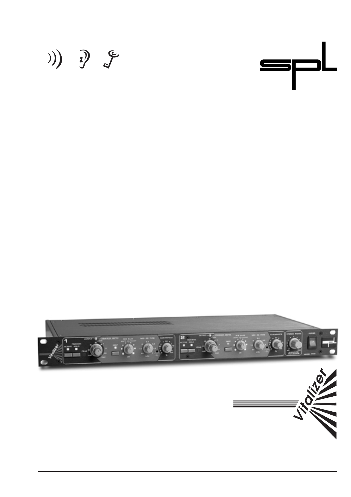
CLASSIC VITALIZER, Model 9215
Manual
Dual-channel program equaliser
®
soundperformancelab.com
Page 2

2
R & D:Wolfgang Neumann
Version 3.1 – 8/2000
The information in this document has been carefully verified
and is assumed to be correct. However Sound Performance Lab
(SPL) reserves the right to modify the product described in this
manual at any time.Changes without notice.This document is the
property of SPL and may not be copied or reproduced in any
manner,in part or full without the authorisation of SPL.
Limitations of Liability:
In no event will SPL be liable for any damages,including loss of
data, lost profits, cost of cover or other special, incidental, consequential or indirect damages arising from the use of the unit,
however caused and on any theory of liability.This limitation will
apply even if SPL or an authorised dealer has been advised of the
possibility of such damage.
SPL electronics GmbH
P.O. Box 12 27
D- 41368 Niederkruechten, Germany
Phone +49 - 21 63 / 98 34-0
Fax +49 - 21 63 / 98 34-20
eMail: info@soundperformancelab.com
www.soundperformancelab.com
© 2000 SPL electronics GnbH. All Rights Reserved.
Classic Vitalizer · Model 9215
Page 3

3
®
Contents
Welcome!
I would like to start with my thanks to all our staff. Our products
are often tested and compared in many publications as well as by
our customers themselves and constantly attract outstanding
evaluations for their audio performance.
I would like to pass on this broad appreciation to those, who
deserve it – my excellent colleagues.
Hermann Gier
Thanks
Congratulations on the purchase of the CLASSIC VITALIZER.
We are sure that you have as much pleasure using it as we had
making it. Please read this manual carefully to ensure that you
gain all the benefits of this unique program equaliser.
Introduction ............................................................................................ 4
Hook up .................................................................................................... 4
Connections ........................................................................................... 5
Applications
Recording Studio – Setups
1: Vitalizer between Mixer and Recorder ....................................... 6
2: Vitalizer between Noise Reduction and Recorder .................. 6
3: Vitalizer connected to the Master-Inserts ................................. 6
4: Vitalizer between Compressor and Recorder .......................... 7
5: Vitalizer inserted in the Aux Send-/Return-Bus ...................... 7
6: Vitalizer connected to the Channel Strip Inserts .................... 7
Tape Duplication ................................................................................... 8
Broadcast ................................................................................................. 8
P.A. ............................................................................................................. 8
Video & Film Post Production ............................................................ 8
First Steps ................................................................................................ 9
Control Elements
Active ........................................................................................................10
Output .......................................................................................................10
Process Depth – Part 1 .........................................................................10
Process Solo ............................................................................................10
Sub Bass ...................................................................................................10
Deep ..........................................................................................................11
Mid-Hi Tune ............................................................................................11
Q .................................................................................................................11
Process Depth – Part 2 .........................................................................11
Harmonics ...............................................................................................12
Surround Processor ..............................................................................13
Power Supply .........................................................................................13
Specifications ........................................................................................14
Warranty ..................................................................................................15
Page 4

Hook up
4
®
The CLASSIC VITALIZER combines most modern equalisation,
phase shift manipulation and harmonic enhancement to provide
signal enhancement across the entire audio spectrum. Based on
established psychoacoustic and audiometric principles, the
VITALIZER brings mid-range material into sharp focus while
enhancing high frequencies.The attendant harshness introduced
by units that add controlled distortion to the signal is avoided.At
the low end the sub-bass is accentuated without incurring the
penalties of boomyness or clouded low-mid detail that inevitably
occur when conventional equalisers are used. The result is a
sound that is subjectively more powerful, more detailed and
more commercially appealing. Additionally, a separate stereo
width-expander is incorporated which may be used either in
conjunction with the VITALIZER equalisers or on its own.
The VITALIZER may be used on complete mixes or on individual
tracks within a mix.Furthermore,a PROCESS SOLO function allows
the processed signal to be added selectively to different tracks
within a mix using the mixing console’s aux send system. Both
signal channels of the VITALIZER are identical and have separate
controls with the exception of STEREO WIDTH which affects both
channels.If the unit is to be used as two independent mono channels, this control should be set fully counter-clockwise.The VITALIZER may be connected either via suitable signal insert points or
via the aux send/return circuit of a mixing console; in the latter
application,the PROCESS SOLO button must be active.
The Signal Peak LED should light either briefly on signal peaks
or not at all. In operation, the Signal Peak LED comes on 3dB
before the onset of clipping in the processing chain. All front
panel push-button switches have status LEDs that light when the
switch is active.Each channel has an independent ACTIVE/BYPASS
switch. Processing is achieved by adding a treated signal to the
original. The treated signal may be auditioned by depressing the
PROCESS SOLO button.
Packaged in a standard 19" EIA format and occupying 1U
(44,45 mm) of rack space,the VITALIZER can be installed in a standard rack,but it is recommended to support the rear of the case –
especially in touring applications. The VITALIZER should not be
installed near units which produce strong magnetic fields or
extreme heat or directly above or below power amplifiers or
digital processors. If possible, the VITALIZER should be placed in
an 'analogue rack' where the majority (or all) of the equipment
installed is analogue.
• Use a small,flat bladed screwdriver to set the voltage selector to
the voltage for the area in which the unit will be used.
• Never cover up the ventilation slots on the top side of the unit.
• If, during operation, the sound is interrupted or indicators no
longer illuminate, or if abnormal odour or smoke is detected,or
if liquids are spilled on the unit, immediately disconnect the
power cord plug and contact your dealer.
• Only clean the unit with a soft, lint-free cloth. Use only standard
cleaning agents.
Introduction
Page 5
Before connecting the VITALIZER or any other equipment turn off
all power. Adjust the voltage setting on the back so that it corresponds with the local power conditions.
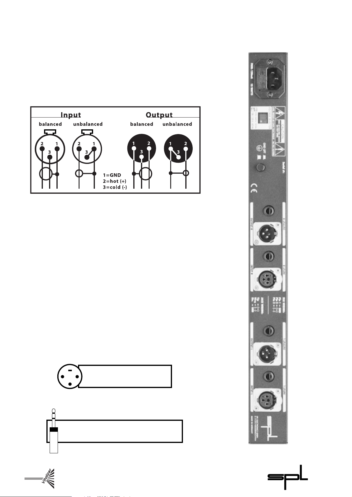
The balanced XLR input connectors are Neutrik XLRs wired pin 2
hot. The unbalanced mono-jacks are wired tip hot. Should the
need arise to use the XLR unit in an unbalanced system, pin 3 of
both the input and output connectors should be grounded.
The following graph shows the correct wiring for connecting
unbalanced signals to the balanced XLR connectors:
Both output stages operate in parallel, so it is possible to connect
two different destination units simultaneously, for example to
record to two different media at the same time or split the output
between a mixer and effects processor. However,only one type of
input (jack or XLR) should be connected at a time – the VITALIZER
is not intended to be used as a mixer!
To ensure optimal signal quality, SPL has developed a new
hybrid-component balanced input/output stage using all lasertrimmed resistors with a tolerance of 0.01 %. This approach has
resulted in an exceptionally high CCMR (common mode rejection); 100dB at 1kHz and 80 dB at 10 kHz.
As a precaution, before connecting the VITALIZER switch off the
power to the unit and to all connected units.
Connections
5
®
Pin wiring Jack connectors
Tip = hot (+), Ring = cold (-),Schaft = GND
1
2
3
Pin-wiring XLR connectors
1 = GND, 2 = hot (+), 3 = cold (-)
Page 6

Studio Application 3:
The VITALIZER connected
to the Master or Subgroup
Inserts of the consoles
Multitrack
Console
Recorder
Inputs (L+R)
Vitalizer Outputs
Master Outputs (L+R)
Vitalizer Inputs
Master or Subgroup Insert Sends
Master or Subgroup-Insert Returns
6
®
1.The most obvious application of the VITALIZER is to process a
final stereo mix, either while mixing or during post-production
prior to cutting.It is important to use full-range monitors to assess
the effect of any bass processing since it is valuable to occasionally
switch the processor in and out of circuit in order to appreciate
how much processing has been added.The brain-hearing system
soon acclimatises to changes in timbre – processing is easily overdone! It is recommended to refer frequently to known recordings.
2. Another popular stereo application is the processing of existing
master tapes during post-production such as remastering archive
material for CD release. If a single-ended noise reduction system
is used to clean up the original, the VITALIZER can make a significant contribution in restoring the high end detail that invariably
suffers during such treatment.
3. When processing stereo-mixes it is recommended to patch the
VITALIZER into the master-breaks of the console. Mostly these
breaks are switched pre-fader, so that the monitoring volume
does not affect the processing intensity,which would be the case
when using the VITALIZER on the master outputs of the console.
Applications
Studio Application 1:
VITALIZER between console
(master outputs) and recorder
Studio Application 2:
The VITALIZER between Noise
Reduction and Recorder to
improve archived recordings
Archived Recording
Noise Reduction
Recorder
Recorder Inputs
(L+R)
Vitalizer
Outputs (L+R)
Outputs (L+R)
Vitalizer
Inputs (L+R)
Inputs
(L+R)
Outputs
(L+R)
Multi-Track
Console
Recorder
Recorder
Inputs (L+R)
Master Outputs (L+R)
Vitalizer Inputs (L+R)
Vitalizer
Outputs (L+R)
Recording Studio
Page 7

4. Another interesting application is the use of the VITALIZER
right after a compressor unit in the master signal chain. Using the
VITALIZER before a compressor can result in more obvious sideeffects of the compressor, such as pumping. It is also possible to
patch the VITALIZER into the aux send system of a console in
much the same way as a reverb or delay unit as long as the
PROCESS SOLO switch is active. The aux return mixing stages in
some consoles are designed in a more cost effective and simpler
way than in the VITALIZER.That’s why it might be possible that the
sonic effect of the VITALIZER sounds different when using the unit
on the aux send/ return system.
5. To obtain better transparency and a full rich sound even if very
long reverb-times are used, the processing of the reverb can be
interesting, too. Connect the VITALIZER right after the reverb unit
and feed the VITALIZER outputs to the aux returns.
6. It is also possible to use the VITALIZER either in place of or to
supplement an equalizer for enhancing individual channels or
sub groups.
Console
Recorder
Compressor
Inputs (L+R)
Vitalizer Outputs
Vitalizer Inputs
Outputs (L+R)
Master Outputs
(L+R)
Multi-Track
Console
Recorder
Reverb
Recorder Inputs
(L+R)
Master Outputs (L+R)
Aux Sends (L+R)
Aux Returns (L+R)
Multi-Track
Applications
7
®
Studio Application 5:
The VITALIZER inserted in the
Aux Send/Return-Bus to improve
the reverb signal
Studio Application 4:
If used together with a
compressor,the VITALIZER is to be
inserted behind the compressor
Console
Recorder
Recorder Inputs
(L+R)
Master Outputs (L+R)
Insert Send 1 (e. g. vocals)
Insert Return 1 (vocals)
Insert Send 2 (e. g. bass)
Insert Return 2 (bass)
Multi-Track
Studio Application 6:
The VITALIZER connected to the
Inserts of two channel strips
to improve single instruments
and vocals
Page 8

8
®
Tape duplication is often made at high speed, resulting in a deterioration of the high frequency spectrum of the copies. By processing the output from the source machine, additional brightness
can be added to compensate for deficiencies in the copying
system. It may also be necessary to modify the bass end as many
high speed systems fail to reproduce the bass end of the spectrum faithfully. In both applications, the VITALIZER is both effective and simple to set up.
The VITALIZER is perfectly suited for the production of radio
jingles,commercials and station idents.Due to the unique processing of the VITALIZER the treated signal will appear louder, closer,
brighter and more intelligible than those signals broadcasted
without VITALIZER processing.In commercial radio, the VITALIZER
can be used to process the entire on-air signal helping the radio
station stand out from the competition. The integral STEREO
WIDTH expander creates a wider stereo spread for those listeners
using a narrow speaker geometry (e. g. car and portable systems).
In live performances or in club installations, the VITALIZER is a
powerful ally in maintaining speech intelligibility under difficult
conditions. It is also of great benefit in systems designed to play
recorded music because the hearing sensation of loudness can
be maintained at lower absolute SPLs. This could be particularly
beneficial with the introduction of new noise level legislation. On
the subjective side, the VITALIZER helps produce a detailed, tight
sound, even from indifferent speaker systems giving an improvement in perceived audio quality.
As in other areas,the VITALIZER can be used to optimise dialogue,
especially when the microphone placement is inadequate (for
example when the mic must be kept out of shot). Music soundtracks benefit in the same way as described for audio-only applications.For most soundtrack producers the enormous ease of use
compared with tuning multi-band equalisers means to save a lot
of wasted time.
Time-compressed audio can also be treated to restore the lack
of timbre.This is particularly valid in the case of vocal narratives as
even a relatively small amount of time compression or expansion
can dramatically compromise the sound quality.
On the post production work on Spike Lee´s “Malcom X” the
voice of Denzel Washington playing Malcolm X was treated with
the Vitalizer for dramatical reasons:
“We wanted to make sure that there was a dramatic quality
difference between the voice-over and the sync dialog,”
Fleischman adds,offering a mixer´s view.“You try to find a balance
between two center mics then balance that with whatever you´re
using from left-right pair.We then treated it with the SPL Vitalizer,
a program equalizer. It brings a lot more presence to the upper
end of the spectrum and a very deep low end so that the voice
sounds full.”(Mix Magazine)
Applications
Broadcast
P. A .
Video & Film
Post Production
Tape Duplication
Page 9

9
®
Both channels of the VITALIZER are set-up identically and can be
controlled separately – except the STEREO WIDTH control. If the
channels are to be used separately, the STEREO WIDTH control is
to be set to OFF. If the VITALIZER is connected to the ,,Aux Send/
Return”Bus,the PROCESS SOLO circuitry must be activated.
Check the PEAK LED regularly: short illuminating indicates
peaks at about 3 dB below clipping – constant illumination is to
be avoided. Please contact SPL if you are not satisfied with the
Input Level adjustment.All front switch positions are indicated by
Status-LEDs.The ACTIVE button switches each channel in or off.
When setting up the VITALIZER for the first time, it is recommended to approach the controls in a specific order to achieve
positive results right from the start.
Initially,set the SUB BASS and HARMONICS controls to 0. Please
note that the SUB BASS control is off in its center position, not
when set fully counter-clockwise.
Set the MID-HI TUNE control to around 3.5kHz and then
advance the PROCESS DEPTH control until the processing can be
heard.You should hear a change in the mid-range but no appreciable change at the bass end.
To hear the effect of the MID-HI TUNE control in isolation, increase the PROCESS DEPTH and set the SUB BASS and HARMONICS
controls to 0.
Next, try advancing the SUB BASS control both clockwise and
counter-clockwise and listen to the different effect on the
character of the bass end.At this point,it is also interesting to hear
the difference the DEEP button makes (full-range monitors
needed; near-field monitors do not generally have the necessary
low frequency capability to reveal the extent of the lowfrequency processing applied by the VITALIZER).
To hear the effect of the SUB BASS in isolation, turn up the
PROCESS DEPTH control,set HARMONICS to minimum and set the
MID-HI TUNE fully counter clockwise to its maximum frequency of
22 kHz.
In the next step, advance the HARMONICS control and listen to
the high end details.To hear the effect of this control in isolation,
set the PROCESS DEPTH to minimum. Note that the MID-HI TUNE
frequency control still influences the action of the HARMONICS
section.
Finally, turn up the STEREO WIDTH control to the 12 o’clock
position and note the soft spreading stereo image.
First Steps
Page 10

10
®
Control Elements
The ACTIVE-function allows to switch between the processed and
unprocessed signal. The green status LED indicates that the
channel is active.A relais hard bypass circuitry works on both XLR
and Jack connections. In case of a power failure the unit is switched to hard-bypass.
The outer ring of the dual-concentric control sets the output level
and is usually set in its fully clockwise position giving unity gain.
However, intensive processing, especially of the bass end, may
increase the overall signal level.The GAIN control may be used to
control the output accordingly.
The inner ring of the dual-concentric control regulates the intensity of the equalisation process. The effect only pertains to the
SUB BASS and MID-HI TUNE controls.Effects generated using the
HARMONICS or STEREO WIDTH controls are not affected.
The PROCESS SOLO button may be used to compare the
processed signal with the dry signal. Alternatively a processed
only output can be created (necessary when using the VITALIZER
in the effects send/return loop of a mixing console).
The SUB BASS control is arranged so as to have no effect when set
to its central position denoted by a ~ on the scale.Turned clockwise, the processing produces a tight, punchy bass sound free
from boomyness. The scale markers in the clockwise half of the
scale are square markers to give a visual indication that a tight or
sharply defined bass sound is being produced.
When turned in the counter-clockwise direction, a very deep,
warm bass sound is created. This is denoted by circular markers
on the counter-clockwise half of the scale suggesting a ”rounded”
sound.The processing increases the more the controls are turned
from it’s centre position.
As with the MID-HI TUNE control, the amount of processed
signal added to the main signal is determined by the setting of
the PROCESS DEPTH control.
Active
Process Depth
(Part 1)
Process Solo
Sub Bass
Output
Page 11

11
®
Control Elements
The DEEP button spreads the frequency range around which the
SUB BASS is centered. Also the level is increased by +4 dB at the
centre frequency of 50 Hz.
This affects both the hard and soft bass settings giving the
choice of four possible permutations.
Equalising the mid-range signal according to the dynamics and
spectral content of the input signal, the VITALIZER improves the
focus of mid-range detail while modifying the overall signal
response curve to create an impression of increased loudness.
The degree of processing is controlled by the PROCESS DEPTH
control while the MID-HI TUNE control is used to set the lower
frequency limit at which processing will take place.
With the control set fully counter-clockwise at 22 kHz, no
audible processing will be evident as the filters are limiting
processing to those frequencies outside the human range of
hearing. However, if you turn the PROCESS DEPTH control fully
clockwise you will hear the high end starting to sound duller than
the dry signal. This effect can be used to dull out very bright
signals. By decreasing the frequency setting, the processing will
become more evident. Additionally, the lower the frequency is
set,the more obvious the effect becomes since more of the audio
spectrum is being treated.
It is generally best to start off with this control set to somewhere between 3 kHz and 6 kHz and then fine tune by ear.
Adjusting the bandwidth preset control (”Q”, inside the front
panel) changes the characteristics of the MID-HI TUNE filter. The
VITALIZER is shipped with the Q setting in its minimum position
(counter-clockwise) which is best suited to general purpose
processing. A higher Q may be selected in order to selectively
enhance certain parts of the audio spectrum such as hi-hats as
may be desirable when mastering a record or reworking an
existing recording.
If the Q control is advanced too far clockwise, the filter is likely
to oscillate. In this case the control should be backed off until
oscillation ceases.For stereo applications,care should be taken to
ensure that the Q presets on either channel are set up as similarly
as possible to eliminate the possibility of spectrally related image
shifts.
This control affects the amount of SUB BASS and MID-HI TUNE
filter signal added back into the mix and will cause certain dominating mid-range frequencies to be attenuated increasing the
overall sense of loudness. Since the human ear perceives the
audio spectrum differently at different SPLs (sound pressure
levels),the VITALIZER reshapes the spectrum so as to convince the
human brain/hearing system that the sound being heard is
louder than it actually is.
Deep
Mid-Hi Tune
Q
Bandwidth Setting of Mid-Hi Tune
Process Depth
(Teil 2)
Page 12

12
®
Advancing the setting of the PROCESS DEPTH control simultaneously increases the amount of MID-HI TUNE filter and SUB BASS
signals in the mix while attenuating other midrange frequencies
to enhance the sense of loudness,thus increasing clarity,bass end
punch and overall power.
Because the PROCESS DEPTH control is really varying three
parameters at once, it is worthwhile setting aside a little time to
explore the important interaction between the PROCESS DEPTH,
SUB BASS and MID-HI TUNE controls.
This harmonic enhancement circuitry is based on fourth-order
filters and phase manipulation, effectively restoring harmonics
that have been corrupted during the recording process or by
other equipment in the processing chain. It may also be used to
increase the subjective brightness of a sound without introducing harshness. Used as an effect, this process is useful for increasing the intelligibility and intimacy of vocals.
The harmonic circuitry is driven by a signal combining the
original, ”dry” signal and the output signal of the MID-HI TUNE
filter. The HARMONICS control determines how much of the
restored harmonics are added back to the original signal.Though
the circuitry of the VITALIZER is inherently very quite, please note
that applying any significant degree of high frequency processing will show up any noise present as part of the signal source.
For this reason, the signal source should be as noise-free as
possible. The harmonics control is independent of the PROCESS
DEPTH control.
Control Elements
Harmonics
Diagram:
„Curves of equal loudness“
according to psychoacoustic
researches by Fletcher and
Munson
Sound Pressure Level in dB
Newton/m
2
Threshold of pain
Loudness level
Frequency in Hertz
Page 13

13
®
Control Elements
Working on established inter-channel phase principles, the
STEREO WIDTH control increases the subjective soundstage
width of any stereo source. The off-centre signals of the stereo
source are detected and fed back phase inverted to the opposite
channel. This effect can be applied to overall mixes as well as to
single instruments.Very interesting is the spreading of the stereo
image of overhead mics of drums-sets,choruses or horn sections.
The Surround Processor section is independent from all other
processes and is not affected by the ACTIVE buttons or PROCESS
DEPTH controls. To deactivate the effect of this section, the
STEREO WIDTH control should be set fully counter clockwise. In
standard applications a STEREO WIDTH setting above the
2 o’clock position is not recommended for complete mixes.
However, such settings can produce some very interesting special
effects for single instruments.
Special care has gone into the design of the power supply of the
VITALIZER – the better it is, the better the system works. In an
audio system,this translates into better sound quality,lower noise
and lower distortion.
The power supply is based around a 15VA toroidal transformer
and is designed to minimise induced hum and noise due to the
lack of an air-gap.
The primary voltage may be selected between 230 V / 50Hz and
115 V / 60 Hz by means of a recessed slide switch on the rear panel
and a rear-panel ground-lift switch is fitted for use where ground
loops are causing hum problems.When the Gnd Lift switch is set
to off,the circuit ground is isolated from the chassis ground.
The detachable power cord is a standard 3-wire type fitted with
an IEC mains connector; the transformer, power cord and mains
connector have VDE, UL and CSA approvals.
The fuse has a value of 315 mA for the primary voltage.
On the secondary side of the power supply,an RC combination
is used to filter out noise and hum voltages. Both half-waves are
smoothed with 4000 microF capacitors in the positive and negative supply path, and both lines use precision voltage regulators
for optimum stability. Deviations of only a few millivolts can
impair audio quality, introducing artifacts such as loss of stereo
imaging or a diffused sound character.
Surround Processor
Power Supply
Page 14

14
®
Frequency response: ...................................... 20 Hz-22kHz, +1 - 0.25dB
THD: ...................................................................... 0.002% @ 1 kHz
... 0.105% @ 10 kHz
S/N (CCIR 468): .................................................. Bypass:-96 dBu
... In/Effekt min:-78 dBu
XLR Inputs:
Electronically balanced (differential),transformerless
Impedance: ........................................................ 20 kOhm
Nominal input level: ....................................... + 6 dB
Maximum input level: .................................... + 22 dBm
XLR Outputs:
Electronically balanced (differential),transformerless
Impedance: ........................................................ >75 Ohm
Nominal output level: .................................... + 6 dB
Minimum load ohms: ..................................... 600 Ohm
XLR-wiring: ........................................................ Pin 2 = (+); Pin 3 = (-)
Jack Inputs:
Unbalanced
Impedance: ........................................................ = 20 kOhm
Nominal input level: ....................................... 0 dB
Maximum input level: .................................... +22 dBm
Jack Outputs:
Unbalanced
Impedance: ........................................................ <600 Ohm
Nominal output level: .................................... 0 dB
Minimum load ohms: ..................................... 600 Ohm
Jack Wiring:Tip = (+); Shield = GND
Power Supply:Toroidal transformer
Primary Voltage Selectable (230 V / 50 Hz or 115 V / 60 Hz)
AC cord:IEC mains connector with detachable 3-wire,U-ground
power cord
PCB Ground-Lift (Gnd Lift) switch on rear panel
Fuse:630 mA
Operating Temperature: + 10°C - + 40°C
Relative Humidity: 5% - 92%
Dimensions:19“ EIA rack mounting unit, 482 x 44 x 232 mm
Specifications
Page 15

15
®
SPL electronics GmbH (hereafter called SPL) products are
warranted only in the country where purchased, through the
authorized SPL distributor in that country, against defects in
material or workmanship. The specific period of this limited
warranty shall be that which is described to the original retail
purchaser by the authorized SPL dealer or distributor at the time
of purchase.
SPL does not, however, warrant its products against any and all
defects:
1) arising out of materials or workmanship not provided or
furnished by SPL, or 2) resulting from abnormal use of the
product or use in violation of instructions, or 3) in products
repaired or serviced by other than authorized SPL repair facilities,
or 4) in products with removed or defaced serial numbers,or 5) in
components or parts or products expressly warranted by another
manufacturer.
SPL agrees, through the applicable authorized distributor, to
repair or replace defects covered by this limited warranty with
parts or products of original or improved design, at its option in
each respect, if the defective product is shipped prior to the end
of the warranty period to the designated authorized SPL warranty
repair facility in the country where purchased, or to the SPL
factory in Germany, in the original packaging or a replacement
supplied by SPL, with all transportation costs and full insurance
paid each way by the purchaser or owner.
All remedies and the measure of damages are limited to the
above services. It is possible that economic loss or injury to
person or property may result from the failure of the product;
however, even if SPL has been advised of this possibility, this
limited warranty does not cover any such consequential or incidental damages.Some states or countries do not allow the limitations or exclusion of incidental or consequential damages, so the
above limitation may not apply to you.
Any and all warranties,express or implied, arising by law,course
of dealing, course of performance, usage of trade, or otherwise,
including but not limited to implied warranties of merchantability and fitness for particular,are limited to a period of 1 (one) year
from either the date of manufacture. Some states or countries do
not allow limitations on how long an implied warranty lasts, so
the above limitations may not apply to you.
This limited warranty gives you specific legal rights, and you
may also have other rights which vary from state to state,country
to country.
SPL electronics GmbH
41372 Niederkruechten, Germany
Warranty
 Loading...