

Page 1
Owner‘s Manual
SPL Router
Model 2269
8 Channel Stereo Router
Page 2

Owner‘s Manual SPL Router
Version 1.1 – 3/2003
R&D: Ruben Tilgner
The information in this document has been carefully verified and is assumed
to be correct. However Sound Performance Lab (SPL) reserves the right to
modify the product described in this manual at any time. Changes without
notice. This document is the property of SPL and may not be copied or reproduced in any manner, in part or full without the authorization of SPL.
Limitations of Liability:
In no event will SPL be liable for any damages, including loss of data, lost
profits, cost of cover or other special, incidental, consequential or indirect
damages arising from the use of the unit, however caused and on any theory
of liability. This limitation will apply even if SPL or an authorized dealer has
been adviced of the possibility of such damage.
Model 2269
As with all SPL products, the SPL Router is conceived, designed and handbuilt in Germany.
Sound Performance Lab
SPL electronics GmbH
P.O. Bo x 1 2 2 7
D- 41368 Niederkruechten, Germany
Phone +49 2163 983 40
Fax +49 - 2163 983 420
eMail: info@soundperformancelab.com
www.soundperformancelab.org
© 2003 SPL electronics GmbH. All rights reserved. Technical specifi cations and appearance subject to
change without notice.
2
Page 3

Introduction ............................................................................................... 3
Hookup and Security Advices ..................................................................... 3
Rear Panel/Connections ............................................................................. 4
Front Panel ................................................................................................. 7
Applications ............................................................................................... 9
Technical Specifications ............................................................................. 10
Warranty .................................................................................................... 11
The SPL Router is a flexible switchbox suited for a wide variety of applications.
With it, you can easily route a stereo signal to eight stereo outputs, or eight
stereo signals to one stereo output. Switching is fully balanced using high
quality switches, and all inputs and outputs are balanced, ensuring professional audio quality.
Additional features include:
• Up to +10 dB of preamplification for input signals
• Onboard headphone amp with mono switch in the output section for comfortable direct monitoring of the selected signal
Content
Introduction
• Line output with level control allows direct connection of active speakers.
A switchable FIXED mode is provided for insert applications, which routes
the selected signal 1:1 to the output.
Hookup and Security Advices
Carefully select a place for setting up the SPL Router. The unit should be
situated away from heat sources and direct sunlight. Avoid installation in environments exposed to vibrations, dust, heat, cold or moisture. Keep the unit
away from transformers or motors or any other unit that could generate large
variations in power supply or cause electrical interferences. Do not install the
unit in proximity to power amplifiers or digital processors. You may consider
placing it in a rack containing other analog gear. Such placement can prevent
interference from Word Clock, Smpte, MIDI, etc.
• Do not open the case. You may risk electric shock and may damage your
equipment.
• Leave repairs and maintenance to a qualified service technician. Should
foreign objects fall inside the case, contact your authorized dealer or suppor t
person.
• To avoid electric shock or fire hazards do not expose your unit to rain or
dampness.
• In case of lightning unplug the unit. Please unplug the cable by pulling on
the plug only; never pull on the cable.
• Never force a switch or knob.
• To clean the case use a lint-free cloth. Avoid cleaning agents as they may
damage the chassis. Manufactured in standard 19“ EIA format, it utilises
two rack units.
• Please support the back of the unit whenever it is being mounted into a
19 inch rack (especially important when touring).
3
Page 4
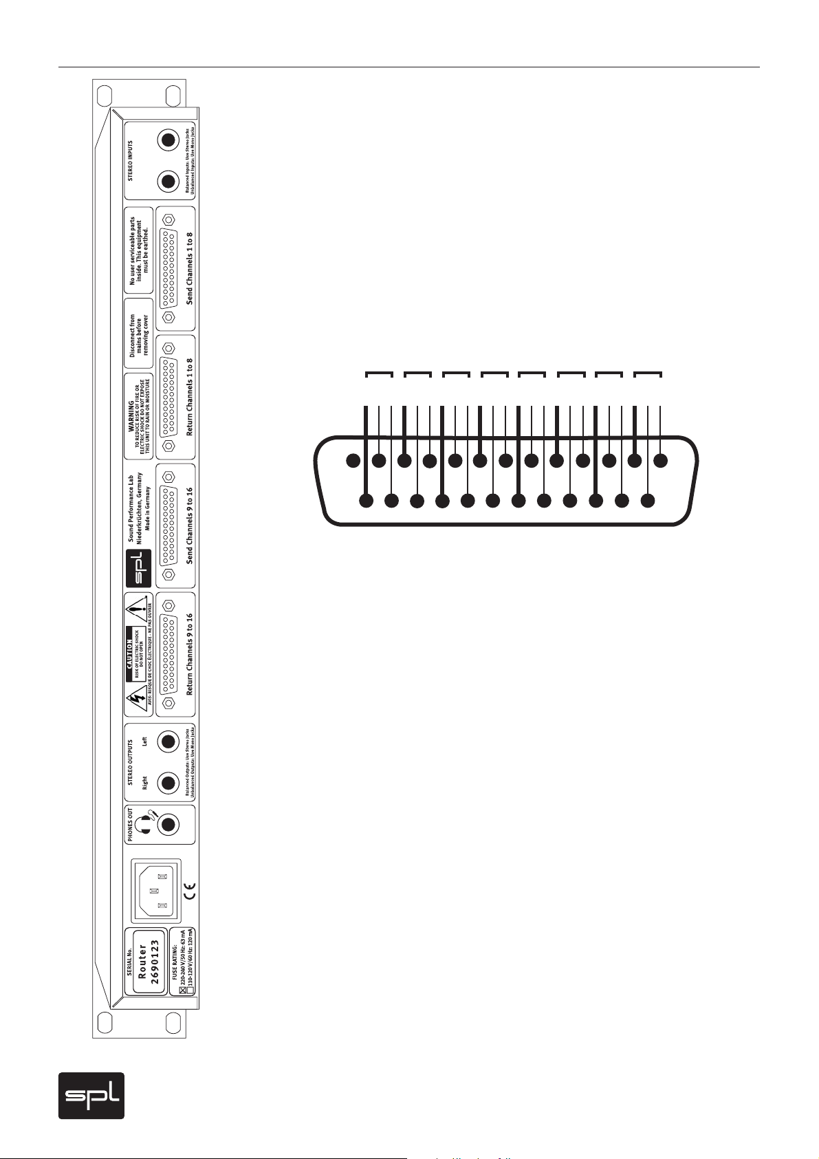
Rear Panel/Connections
STEREO INPUTS
For connection of the source signal, which will be routed to the eight outputs.
Use 1/4” TRS (stereo) plugs for balanced connections and 1/4“ TS (mono)
plugs for unbalanced signals. Maximum input level is +19 dBu.
SEND CHANNELS 1 TO 8
These connectors provide the balanced SEND signals from stereo channels
1 to 4 for connection to processor inputs. A send channel will only carry the
input signal if the corresponding switch is activated. Standard adapter cables
are readily available for these connections (Sub-D > XLR male or female or
Sub-D > 1/4“).
The Sub-D connectors are wired according to the Tascam standard:
1234567 8
GCHGCHGCHGCHGCH GCHGCHGCH
13
25
G= GROUND, C=COLD (-), H=HOT (+)
The numbers on the cables correspond to the Router send channels as
follows:
Cable No. Send Channel Switch Position
1 Send 1 Left
1
2 Send 1 Right
3 Send 2 Left
4 Send 2 Right
5 Send 3 Left
6 Send 3 Right
7 Send 4 Left
8 Send 4 Right
}
}
}
}
2
3
4
1
14
Example: if switch 1 is activated, the lef t side of the stereo signal is present at
cable no. 1 and the right side at cable no. 2. Switch 2 routes the stereo signal
to cables 3 and 4 and so on.
4
Page 5

Rear Panel/Connections
RETURN CHANNELS 1 TO 4
These connectors provide the balanced RETURN signal from stereo channels 1
to 4 for connection to processor outputs. These signals are routed to the headphone amp and the line out according to the switch positions. Once again, the
connectors are wired according to the Tascam standard. The numbers on the
cables correspond to the Router return channels as follows:
Cable No. Return Channel Switch Position
1 Return 1 Left
1
2 Return 1 Right
3 Return 2 Left
4 Return 2 Right
5 Return 3 Left
6 Return 3 Right
7 Return 4 Left
8 Return 4 Right
}
}
}
}
2
3
4
SEND CHANNELS 9 TO 16
These connectors provide the balanced SEND signal from stereo channels 5 to
8 for connection to processor inputs. The numbers on the cables correspond
to the Router send channels as follows:
Cable No. Send Channel Switch Position
1 Send 5 Left
5
2 Send 5 Right
3 Send 6 Left
4 Send 6 Right
5 Send 7 Left
6 Send 7 Right
7 Send 8 Left
8 Send 8 Right
}
}
}
}
6
7
8
5
Page 6

Rear Panel/Connections
RETURN CHANNELS 5 TO 8
These connectors provide the balanced RETURN signal from stereo channels
5 to 8 for connection to processor outputs. The numbers on the cables correspond to the Router channels as follows:
Cable No. Return Channel Switch Position
1 Return 5 Left
2 Return 5 Right
3 Return 6 Left
4 Return 6 Right
5 Return 7 Left
6 Return 7 Right
7 Return 8 Left
8 Return 8 Right
}
}
}
}
5
6
7
8
STEREO OUTPUTS
These connectors provide the balanced return signal from channels 1 to 8
according to the switch positions for connection of active speakers or other
monitoring systems. The level is controlled by the LINE OUT pot. If FIXED
mode is activated (switch depressed), the return signals are passed 1:1 to the
STEREO OUTPUTS.
PHONES OUT
This stereo connector provides the same signal as the front-panel headphones
output. Its level is also controlled by the VOLUME pot on the front panel. You
can connect two headphones at a time (see page 8, PHONES OUT).
AC
For connection of the Router to AC power using the included power cord.
6
Page 7

MIC INPUT
This connector allows you to connect a microphone and route it to eight
external devices. One possible application would be easy comparison of up
to eight mic preamps or other external processors with a single microphone.
A condenser microphone may be used, although switching noises may occur
due to phantom power. In this ca se, we recommend that you reduce the output
volume before switching.
LINE/MIC Switch
This switch allows you to easily select between two connected sources. With
the switch depressed (LED illuminates), the microphone input signal is routed
to the outputs.
NOTE: The microphone signal is only routed to the left channels; right chan-
nels will still carry the line signal (if present). Always use the left channel
(odd adapter cable numbers) when connecting to the inputs of various mic
preamps or other external processors. The external equipment‘s outputs may
be connected to either left or right channels. The MONO switch on the Router
should be activated so that the microphone signal is heard on both channels.
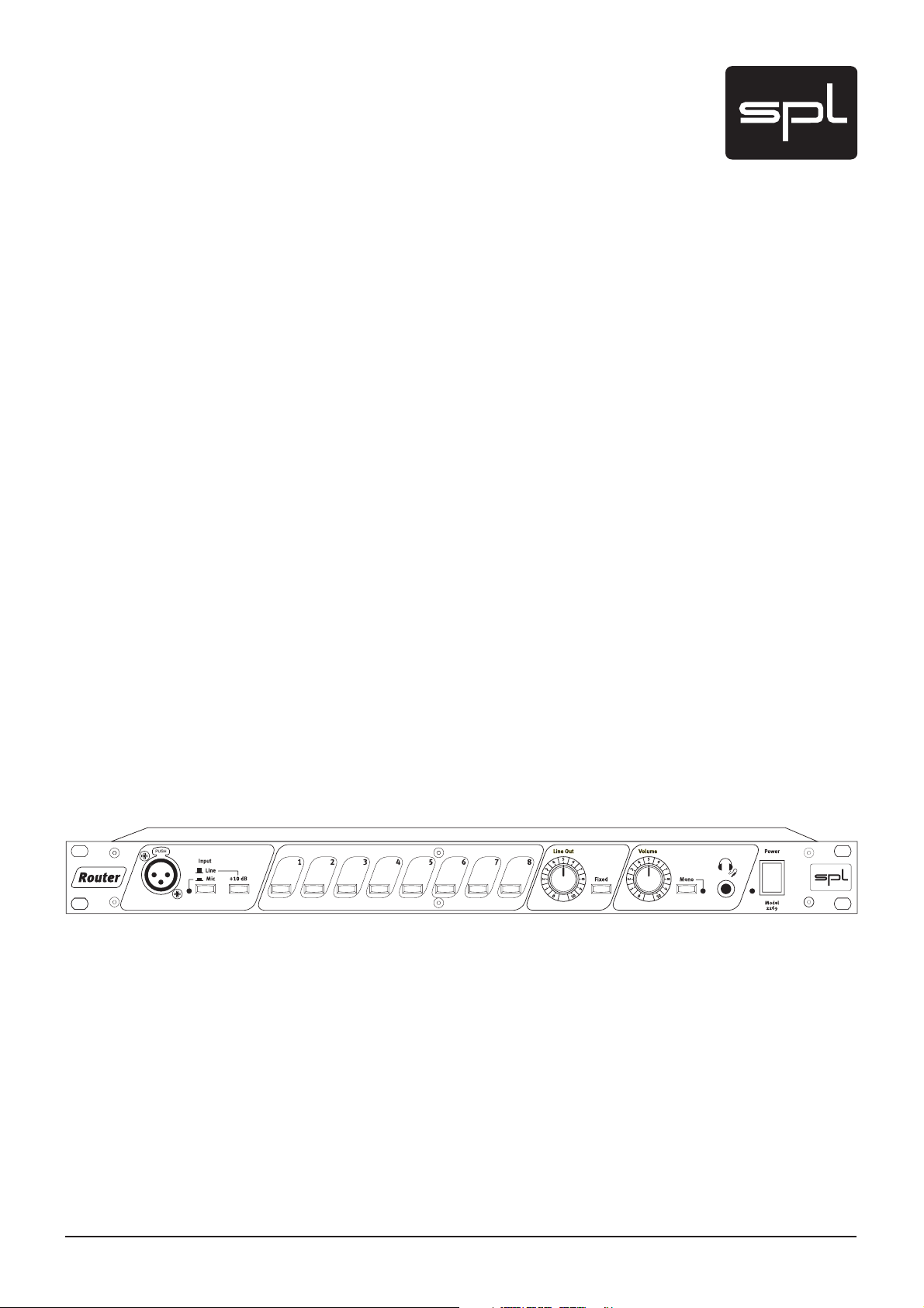
Front Panel
Switches „1“ bis „8“
These switches route the input signal to the corresponding sends, e.g. external
devices. A switch must be activated in order for the corresponding device to
receive the signal.
+10 dB
This switch allows you to increase the Router‘s input level by 10 dB. This is
often necessary when using commercial CD players or similar devices with low
output levels in conjunction with professional audio equipment.
LINE OUT
This pot controls the output level at the STEREO OUTPUTS. If for example
active speakers are connected to these outputs, the volume can be controlled
via the LINE OUT pot.
FIXED
This switch routes the return signal 1:1 to the STEREO OUTPUTS, bypassing
the LINE OUT level control. The Router should always be in FIXED mode when
used to switch between various insert devices.
7
Page 8

Front Panel
VOLUME
This pot controls the level of the front- and rear-panel headphone outputs.
MONO
This switch converts the signal at the headphone and line outputs into a mono
signal. The MONO switch should be activated when mono processors are
connected or when microphones are used as a signal source (see above).
With the MONO function, it is also very easy to check for mono compatibility
of stereo effects.
PHONES OUT
This connector allows you to connect standard stereo headphones. When
using two sets of headphones (via the front- and rear-panel connectors), both
sets should ideally have the same impedance. Otherwise, they could vary
greatly in volume.
POWER-Schalter
You guessed it: this switch turns the Router on and off. The LED illuminates
when power is on.
8
Page 9

Selection of processors at the master insert of a console
By connecting the Router to a console‘s master insert you can connect up
to eight various processors for easy comparison/selection, eliminating timeconsuming patching and re-patching.
Connect the console‘s master insert sends to the Router‘s STEREO INPUTS,
and the Router‘s STEREO OUTPUTS to the console‘s master insert returns.
Select LINE on the front-panel INPUT switch. The +10 dB switch should be
deactivated and FIXED mode activated so that the Router does not affect
levels. Now the units can be connected to the router for comparison.
Expanded source switching in connection with a console
The Router can easily expand your console‘s source inputs, allowing you to
monitor up to eight additional stereo sources. Simply connect your additional
sources (CD, DAT, TV, Video etc.) to the Router‘s RETURN CHANNELS, and its
STEREO OUTPUTS to your console‘s master input. The Router should be in
FIXED mode. You can also directly monitor your sources via the Router‘s headphone outputs.
Applications
Speaker selection
The Router can also select and/or compare various speaker systems. Connect
your stereo signal (e.g. console main outs) to the Router‘s STEREO INPUTS
and your amplifiers or active speakers to the SEND CHANNELS. The INPUT
switch should be set to LINE and the +10 dB switch deactivated.
Signal processor comparison/selection
The Router is an excellent tool for comparison and demonstration of various
signal processors (equalizers, compressors, reverb or multieffects units) in a
retail setting. Simply connect a CD player to the STEREO INPUTS, the SEND
connectors to the processors‘ inputs and the processors‘ outputs to the
RETURN CHANNELS. The INPUT switch should be set to LINE and the +10 dB
switch activated if necessary. Depending on the situation, the various processors can be compared via headphones (PHONES OUTs) or active speakers
(STEREO OUTPUTS). Use the LINE OUT pot to control the volume (FIXED mode
must be deactivated).
Mic preamp comparison/selection
Similarly, the Router can be used for comparison and/or selection of various
preamps. Connect a microphone to the MIC INPUT and set the INPUT switch
accordingly. Connect the left SEND channels to the mic preamps‘ inputs and
their outputs to either side of the Router‘s RETURN channels. Activate the
MONO switch. For accurate comparison, be sure that all preamps are set
to equal levels. If you are using a condenser mic, you will need to activate
phantom power.
NOTE: Switching noises may occur due to phantom power. We recommend
that you reduce the output volume before switching when using condenser
microphones.
9
Page 10

Technical Specifi cations
STEREO INPUTS/SEND connectors
Maximum input level: +19 dBu
Input impedance: 10 kOhms
CCMR (1 kHz): › 70 dB
Maximum output level: +20 dBu
THD+N (+10 dBu): › 105 dB
Noise: -98.2 dBu
Noise (+10 dB): -89.5 dBu
Freq. response (-0.5 dB): 10 Hz-80 kHz
STEREO OUTPUTS/RETURN connectors
Maximum input level: +19 dBu
Input impedance: 10 kOhms
CCMR (1 kHz): › 70 dB
Maximum output level: +19 dBu
THD+N (+10 dBu): › 100 dB
THD+N (Fixed): › 112 dB
Noise: -98.2 dBu
Freq. response (-0.5 dB): 10 Hz-80 kHz
PHONES OUT
Output impedance: 0.2 Ohms
Maximum output voltage: 50 Ohms: 3.57 Veff
150 Ohms: 5.74 Veff
300 Ohms: 6.73 Veff
600 Ohms: 7.11 Veff
THD+N (150 Ohms, 4 Veff): › 95 dB
Power consumption: 7 W
Housing/measures: Standard EIA 19 inch housing, 1 U
44 x 480 x 112 mm (H x B x T)
10
Weight: 2 kg
Techn ica l s pec ifi cations subject to change without notice.
Page 11

SPL electronics GmbH (hereafter called SPL) products are warranted only in
the country where purchased, through the authorized SPL distributor in that
country, against defects in material or workmanship. The specific period of
this limited warranty shall be that which is described to the original retail
purchaser by the authorized SPL dealer or distributor at the time of purchase.
SPL does not, however, warrant its products against any and all defects:
1) arising out of materials or workmanship not provided or furnished by SPL,
or
2) resulting from abnormal use of the product or use in violation of instruc-
tions, or
3) in products repaired or serviced by other than authorized SPL repair
facilities, or
4) in products with removed or defaced serial numbers, or 5) in components
or parts or products expressly warranted by another manufacturer.
SPL agrees, through the applicable authorized distributor, to repair or
replace defects covered by this limited warranty with parts or products of
original or improved design, at its option in each respect, if the defective
product is shipped prior to the end of the warranty period to the designated
authorized SPL warranty repair facility in the country where purchased, or
to the SPL factory in Germany, in the original packaging or a replacement
supplied by SPL, with all transportation costs and full insurance paid each
way by the purchaser or owner.
Warranty
All remedies and the measure of damages are limited to the above services.
It is possible that economic loss or injury to person or property may result
from the failure of the product; however, even if SPL has been advised of this
possibility, this limited warranty does not cover any such consequential or
incidental damages. Some states or countries do not allow the limitations or
exclusion of incidental or consequential damages, so the above limitation may
not apply to you.
Any and all warranties, express or implied, arising by law, course of dealing,
course of performance, usage of trade, or otherwise, including but not limited
to implied warranties of merchantability and fitness for particular, are limited
to a period of 1 (one) year f rom either the date of manufacture. Some states or
countries do not allow limitations on how long an implied warranty lasts, so
the above limitations may not apply to you.
This limited warranty gives you specific legal rights, and you may also have
other rights which vary from state to state, country to country.
SPL electronics GmbH
41372 Niederkruechten, Germany
11
Page 12

Owner‘s Manual SPL Router, Model 2269
All you need is imagination, good ears and three letters:
 Loading...