

Page 1
SAE Class 2 LED Beacon
ELB42BM(z)+(x)(y) Magnet Mount
ELB42BC(z)Ø(x)(y) Flat/Pipe Mount
INSTALLATION:
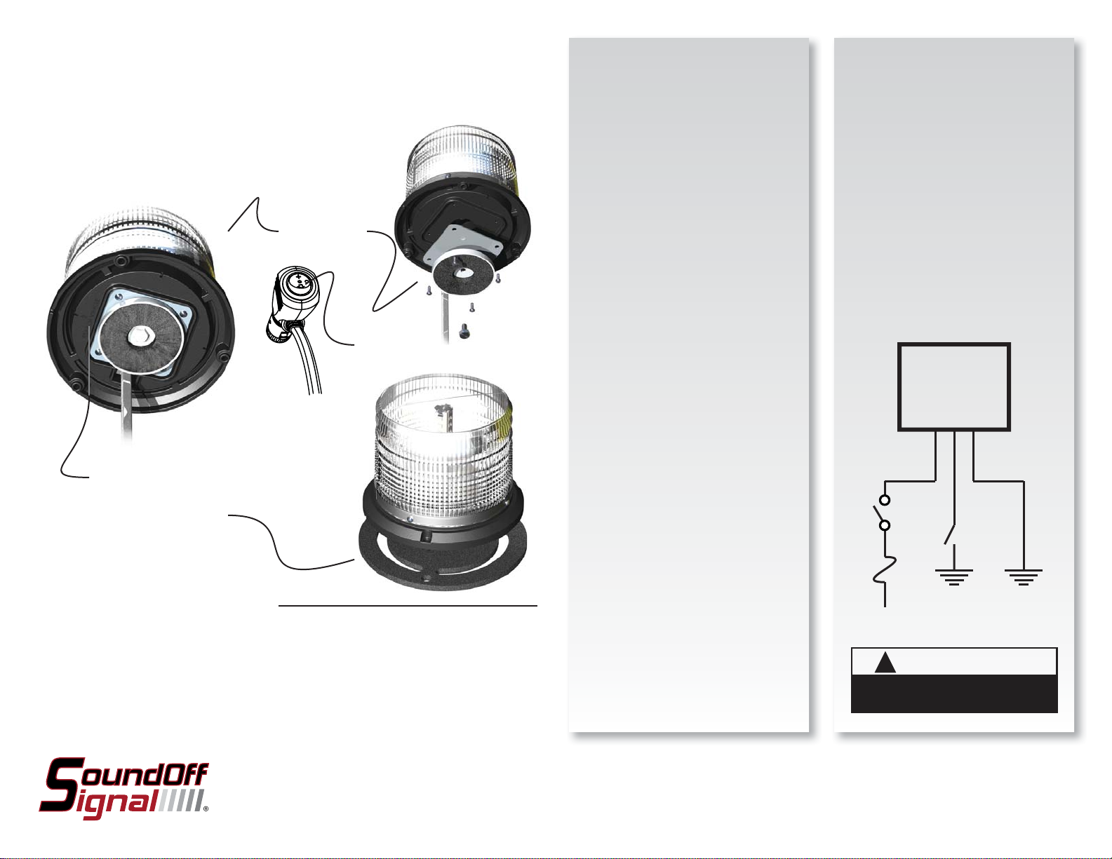
Magnet Mount
1) Install square metal plate with PEM
nut up using M3x10mm screws as
shown.
2) Carefully place beacon on steel top of
vehicle with “Rear of Vehicle” arrow
toward rear.
3) Route wire to 12V socket.
OPERATION:
Magnet Mount
1) Place beacon on roof of vehicle.
2) Route wire through window.
3) Plug into 12V socket.
4) Press arrow on cigar plug >1 sec but
<5 sec: pattern advances 1 step.
5) Press arrow for >5 sec pattern resets
to pattern #1.
MAGNET MOUNT
ELB45BM(z)+(x)(y)
Pattern Select
on Cigar Plug
“REAR OF VEHICLE” ARROW
FLAT MOUNT / PIPE MOUNT
ELB45BC(z)Ø(x)(y)
Please see reverse for
Technical Specifi cations
Important Information:
• Warning devices are strictly regulated and governed by Federal, State and Municipal ordinances.
These devices shall be used ONLY on approved vehicles. It is the sole responsibility of the user of these
devices to ensure compliance.
• DO NOT install this product or route any wires in the Air Bag Deployment Zone. Refer to your vehicle
Owner’s Manual for the location of any air bag deployment zones.
• DO NOT connect this device to a strobe power supply. This product is self-contained and does not
require an external power supply.
Flat Mount
1) Determine location where beacon is
to be installed and drill
n1/2” hole at
the center for cord exit.
2) Using the housing as a guide mark
the centers of hole positions in three
places (note “Rear of Vehicle” Arrow)
and drill appropriate pilot holes.
3) With wire through center of gasket
make electrical connections.
4) Ensure “Rear of Vehicle” Arrow is in
correct position and install 3 screws
being careful not to strip out pilot
holes. DO NOT OVERTIGHTEN.
Pipe Mount
Beacon may be installed on a vertical
pipe with 1” NPT thread.
1) Feed wires through pipe and make
electrical connections.
2) Screw base of beacon to pipe
(clockwise). Adjust pipe or beacon so
that “Rear of Vehicle” Arrow points to
the rear.
Flat / Pipe Mount
1) Connect wires as shown below (note
that white wire is for momentary
ground (used for pattern selection)
and should be taped after pattern is
selected.
BEACON
RED
WHITE
FUSE
5 AMP
+12 Vdc
WARNING
!
This product contains high intensity LED devices.
To prevent eye damage, DO NOT stare into the
light beam at close range.
BLACK
GROUND
MOMENTARY
To review our Limited Warranty Statement & Return Policy for this or any SoundOff Signal product please visit our website at www.soundoffsignal.com and select the “Warranty & Returns”
link along the left column of our home page. If you have questions regarding this product please contact Technical Services, Monday - Friday, 8 am to 5 pm at 1.800.338.7337, press #4 to
skip the automated message. Questions or comments that do not require immediate attention may be emailed to techsupport@soundoffsignal.com.
1.800.338.7337. / www.soundoffsignal.com / Thank you for trusting us with your safety!
ELB42BM(z)+(x)(y) - ELB42BC(z)Ø(x)(y) 2.10
Page 2

SAE Class 2 LED Beacon
ELB42BM(z)+(x)(y) Magnet Mount
ELB42BC(z)Ø(x)(y) Flat/Pipe Mount
TECHNICAL SPECIFICATIONS
Overall Dimensions:
Flash Patterns: 8 fl ash patterns
Input Voltage Range:
Current Consumption: less than 2 amps
# of LEDs: 4 Generation 3 LEDs
Light Sync Technology: Yes
Operating Temperature: -40º to +65º C
Alternating Patterns 1 Light
1. Warp
2. Quad Flash
3. Quint
4. Double Flash
5. Quad2 Flash
2
6. Warp
7. E-Ideal Single Flash
2
8. U
4.86”H x 6.35”n
9 - 30 Vdc
Flash Patterns
Alternating
2 Lights
xx x
xx x
xx x
xx x
xx x
xx x
xx x
xx x
Simultaneous
2 Lights
X-Pattern
4 Lights
FPM
(Flashes per
Minute)
240
81
70
70
67
59
63
176
SAE Class 2 LED Beacon
ELB42BC(z)0(x)(y) Flat/Pipe Mount
NOTE: The Magnet Mount Beacon
CANNOT be synced.
Beacon Light Sync Confi guration Instructions
1. Set ID#
a. Identify which pattern and sequence you want.
b. Connections
i. RED: +12Vdc
ii. WHT: +12Vdc (Note: you will need to disconnect after
power is applied)
iii. BLK: Ground
c. Apply power to unit
d. Without disconnecting power from red wire, disconnect
WHT wire
e. Momentarily connect WHT to Ground to change ID #
i. Identify ID# by number of sequential fl ashes
ii. Possible ID#s: 1 – 4
f. Disconnect power from red wire to get out of ID mode.
2. Set Pattern
a. Reapply power to red wire.
b. Once all Light Head ID#s are confi gured, make sure all
lights are fl ashing the same pattern.
c. Connect corresponding colored wires of all units together:
RED to RED, etc.
d. Change Pattern
i. Momentarily connect WHT wires to Ground
ii. Observe pattern change on all lights connected
e. Insulate all wire connections
3. Reset Pattern
a. Remove power
b. Place WHITE (sync) wire to ground
c. With sync wire grounded, re-power RED wire
d. Maintain for one second (light will dim)
e. Remove power and ground (pattern 1 set)
(ELB45BM(z)+(x)(y))
Replacement Parts & Accessories:
E36ØBG4: Metal Branch Guard for 4” Low Dome
E36ØBG6: Metal Branch Guard for 6” High Dome
E36ØDC6: Clear Dust Cover for 4” Low and 6” High Dome
ET2BLL(x): Replacement 4” Low Dome
ET2BLT(x): Replacement 6” High Dome
PE2BBDR2: Black Dress Ring
SEQUENCE:
2 LIGHTS
ALTERNATING: To obtain Alternating patterns, follow the ID
SELECTION steps and set one Beacon to ID#1 and the other to
ID#3. Then proceed to the PATTERN SELECTION steps.
SIMULTANEOUS: To obtain Simultaneous patterns, follow the
ID SELECTION steps and set both Beacon lights to ID#1. Then
proceed to PATTERN SELECTION steps.
ELB42BM(z)+(x)(y) - ELB42BC(z)Ø(x)(y) 2.10
 Loading...