

Page 1
IMPORTANT INFORMATION:
Warning devices are strictly regulated and governed by Federal, State and Municipal ordinances. These devices shall be used ONLY on approved vehicles. It is the sole responsibility of the user of these devices to ensure compliance.
To review our Limited Warranty Statement & Return Policy for this or any SoundOff Signal product, visit our website at www.soundoffsignal.com/sales-support.
If you have questions regarding this product, contact Technical Services, Monday - Friday, 8 a.m. to 5 p.m. at 1.800338.7337 (press #4 to skip the automated message).
Questions or comments that do not require immediate attention may be emailed to techservices@soundoffsigal.com.
SUPERIOR CUSTOMER RELATIONSHIPS. SMARTLY DESIGNED LIGHTING & ELECTRONIC SOLUTIONS.
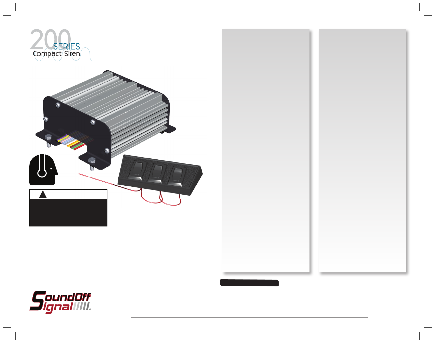
WARNING
ETSA2ØØR
!
Sirens produce loud sounds that
may damage hearing:
- Roll up windows.
- Wear hearing protection.
- Use only for emergency response.
- Avoid exposure to siren sound
outside of vehicle.
Please see reverse for
Technical Specifications
Important Information:
• Warning devices are strictly regulated and governed by Federal, State and Municipal ordinances.
These devices shall be used ONLY on approved vehicles. It is the sole responsibility of the user of these
devices to ensure compliance.
IMPORTANT NOTICE TO
INSTALLER:
Make sure to read and understand
all instructions and warnings before
proceeding with the installation of this
product. Ensure the manual and all
warning cards are delivered to the end
user of this equipment.
Introduction
The ETSA2ØØR is a Compact Siren
Amplifier designed for single 100 Watt
speaker or dual 58 Watt use.
The primary operating modes are User
Selectable Tone, Yelp, Wail, Piercer,
Hi-Lo, Super Hi-Lo, Radio, PA, Horn
Override, and a Manual Override are
available in all modes.
Sirens provide an essential function
of an effective audio / visual warning
system. However, sirens are only short
range secondary devices. The use of
a siren does not insure that all drivers
can or will abide by or react to an
emergency warning signal, especially at
high rates of speeds or long distances.
The operator of the vehicle must never
take the right of way for granted and
it is the operator’s responsibility to
proceed safely.
The effectiveness of this siren system
is highly dependant on the correct
mounting and wiring. The installer must
read and follow the manufacturer’s
installation instructions and warnings in
the manual. The vehicle operator should
verify the siren system is securely
fastened to the vehicle and properly
functioning.
Effective sirens generate loud sound
pressure levels that can potentially
cause hearing damage. Installers and
those around the vehicle need to be
aware of the dangers and wear hearing
protection whenever the siren system
is operating. Vehicle operators and
occupants should assess their exposure
to siren noise and determine what steps
need to be taken to prevent hearing
damage.
The siren system is intended for use
by authorized personnel only. It is the
user’s responsibility to ensure they
understand and operate the emergency
warning devices in compliance with
all applicable city, state, and federal
laws and regulations. SoundOff
Signal assumes no liability for any
loss resulting from the use of the siren
system.
Package Contents:
1 ea. Amplifier
1 ea. Instruction Manual
1 ea. Operators Warning Card to
remain in vehicle for operator
review
1 ea. Sound Pressure Warning Label
that is to be attached in vehicle
and in plain site of operator and
occupants of the vehicle
1 ea. 3 Switch panel with:
1-ON/OFF/ON Switch
2-OFF/MOMENTARY Switch
1 ea. Electrical Isolation Hardware Kit
Wire capacity requirements for siren
amplifier (incoming power + ground)
0-10 Feet: 14 AWG
10-20 Feet: 12 AWG
20-30 Feet: 10 AWG
30+ Feet: Consult Factory to
determine requirements
ETSA2ØØR 5.13
Page 2
ETSA2ØØR
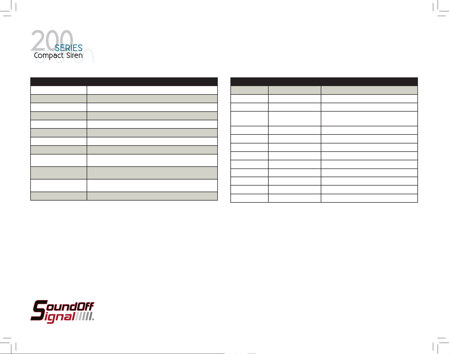
TECHNICAL SPECIFICATIONS
Size Amplifier: 2.3”H x 5.4”W x 4.6”D
Input Voltage: 10 - 30 Vdc (negative ground)
Input Current: 8 Amps @ 13.6 Vdc (100W speaker)
Standby Current: <1 mA
Audio Frequency:
Output Power: 100 WATTS RMS MAX. (11 Ohm Speaker Impedance)
Siren Frequency: 675Hz - 1633Hz
High Voltage Protection: 30 Vdc will cause siren output to cease, resume at normal.
Low Voltage Shutdown: Voltage below 9.0 Volts for 10 seconds or more will cause siren output
Operating
Temperature / Humidity:
Controls: Tone, Yelp, Wail, Horn, Manual, Horn Ring,
Boxed Weight 3 Lbs.
to cease and will resume when system voltage is above 9.0 Volts
-40° F to +110°F temperature, 5-95% Non-condensing humidity
PA VOLUME PROGRAMMING
1. Connect audio source to White/Red wire
2. Connect Grey wire to ground to activate PA
3. Momentarily connect Violet wire to ground to toggle
through the available volume settings.
4. The last volume selected will be programmed to be
used whenever PA control is selected
200Hz - 10 kHz + 3db
Park Kill, Ignition, PA, Radio Rebroadcast
RADIO RE-BROADCAST VOLUME
PROGRAMMING
5. Connect audio source to Blue wires
6. Connect Grey wire to +V to activate Radio Rebroadcast
7. Momentarily connect Violet wire to ground to toggle
through the available volume settings.
8. The last volume selected will be programmed to be used
whenever Radio Rebroadcast is selected
INPUT WIRE HARNESS
WIRE COLOR: FUNCTION ACTIVATION METHOD
TAN Tone 1 Select Connect to +Vdc
BROWN Tone 2 Select Connect to +Vdc
TAN AND
Tone 3 Select Connect to +Vdc
BROWN
RED/BLACK Manual Tone Select Connect to +Vdc
RED Horn Tone Select Connect to +Vdc
ORANGE/BLACK Ignition Input Connect to +Vdc
WHITE/RED PA Audio through Siren Connect PTT Switch wire (Grey) to ground (-)
BLUE Radio Rebroadcast Connect Grey wire to +Vdc
YELLOW Park Kill / Tone Disable Connect to Ground (-)
WHITE Horn Ring Output
WHITE/BLACK Horn Ring Input Ground Input Signal
VIOLET Tone / Volume Program Connect to Ground to change tone / volume
HORN RING TONE ACTIVATION:
When Horn Ring is activated, while Tone 1 is activated,
the siren will switch to Tone 2 for 5 seconds and then
return to Tone 1
When Horn Ring is activated, while Tone 2 is activated,
the siren will switch to Tone 1 for 5 seconds and then
return to Tone 2
When Horn Ring is activated, while Tone 3 is activated,
the siren will switch to Tone 1 for 5 seconds and then
return to Tone 3
HANDS FREE OPERATION:
When the Horn Ring is programmed to a warning tone,
Hands-free operation is enabled. When the Horn Ring
is activated, the tone will sound until the Horn Ring is
activated again. Tone1, Tone2, Tone3, PTT, Manual Tone
and Radio Rebroadcast will override Hands-free operation.
ETSA2ØØR 5.13
Page 3

ETSA2ØØR
TONE SELECT PROGRAMMING
1. Connect the following wires to +Vdc to activate tone that needs to be programmed
WIRE COLOR: FUNCTION
TAN Tone 1 Select
BROWN Tone 2 Select
TAN AND BROWN Tone 3 Select
RED Horn Tone Select
WHITE/BLACK Horn Ring
2. Momentarily connect Violet wire to ground to toggle through available tones
3. The last tone selected will be programmed to be used whenever selected control wires
are activated
4. Repeat steps 1-3 for each tone option
NOTE: Manual Function is NOT programmable.
TONE RESET INSTRUCTION:
INSTALLATION:
1. Mount Amplifier Assembly in a protected location, being careful to route wires away from
any hot surfaces or areas where the wires may get pinched.
2. Locate Green and Green/Black wires that are on opposite corners of all other input/control
wires. These are the outputs to the speaker(s)
3. Connect these 2 wires to the speaker(s) which are installed on the vehicle. The white/
red wire jumper will determine if the amplifier is to operate at an output voltage designed
to drive a single 100 Watt speaker or a single/dual 58 Watt speaker(s). See electrical
schematic on reverse side for more information.
SPEAKER CONFIGURATION WHITE/RED JUMPER WIRE
SINGLE 100 WATT SPEAKER DO NOT CUT
SINGLE 58 WATT SPEAKER Cut and Tape both ends
DUAL 58 WATT SPEAKER Cut and Tape both ends
4. Connect Black wire to reliable ground. Using wire capacity chart as a guideline to
establish wire gauge to use for extending wires.
5. Connect Orange wire to fused constant +Vdc. Using wire capacity chart as a guideline to
establish wire gauge to use for extending wires.
6. Connect Orange/Black wire to ignition switch. +Vdc is required on Orange/Black wire for
siren to operate.
When toggling through available tones, holding the violet wire to ground for more
than two seconds the tone will switch to the default tone.
(See Horn Tone and Warning Tone Table below)
HORN TONE TABLE
HORN TONE 1 Default
HORN TONE 2
HORN TONE 3
HORN TONE 4
SUPER Hi-Lo
CYCLE TONE
WARNING TONE TABLE
WAIL
YELP Tone 2 (default)
ALERT A Tone 3 (default)
PIERCER
Hi-Lo
Tone 1 and Horn Ring
(default)
Plays thru Wail, Yelp, Alert
A and Piercer (Tone changes
every 5 seconds)
7. Connect Tone 1, Tone 2, Manual Tone, Horn Tone wires to provided switch panel as
needed.
8. Program Tones following instructions found earlier in the manual under Tone Select
Programming.
9. Connect Blue wires to radio output if radio rebroadcast feature is required.
10. Connect White/Red wire to PA microphone.
11. Connect PTT / Radio Rebroadcast activation wire and to switch that will supply ground
when activated for PA function and +Vdc when activated for Radio Rebroadcast function.
A Single Pole Double Throw (SPDT) switch with center OFF position will be required for
this.
12. Program Radio Rebroadcast following the Programming instructions found earlier in the
manual under Radio Re-broadcast Volume Programming.
13. Program Radio Rebroadcast following the Programming instructions found earlier in the
manual under PA Volume Programming.
14. (OPTIONAL) Attach Yellow wire (Park Kill) to a switch that will supply ground whenever
the siren is to be disabled.
ETSA2ØØR 5.13
Page 4

ETSA2ØØR
PARK KILL INPUT
PA AUDIO INPUT
TONE 1
TONE 2
MANUAL TONE INPUT
HORN TONE INPUT
IGNITION INPUT
GROUND
TONE SELECT
PTT / RADIO REBROADCAST
PARK KILL SWITCH
PTT SWITCH
RADIO
REBROADCAST
ACTIVATION
SWITCH (9-30Vdc)
PROGRAMMING
SWITCH
INSTALLER
SUPPLIED AND
INSTALLED
10A FUSE
BATTERY
RADIO REBROADCAST
0-5V ANALOG SIGNAL
SUPPLIED
SPLASH-PROOF
FUSEHOLDER W/10A
FUSE
10 amp
Fuse
HORN OUT
HORN IN
ORANGE
TAN
BROWN
RED/BLACK
RED
ORANGE/BLACK
WHITE
WHITE/BLACK
BLUE
BLUE
WHITE/RED
GREY
YELLOW
VIOLET
BLACK
FOR 58 WATT
OPERATION,
CUT AND TAPE
BOTH ENDS
WHITE/RED
JUMPER WIRE
GREEN
GREEN/BLACK
2nd 58 WATT
SPEAKER
(OPTIONAL
58/100 WATT
SPEAKER
PROGRAM:
MOMENTARY
CONNECTION
(GROUND)
ETSA2ØØR 5.13
Page 5

IMPORTANT INFORMATION:
Warning devices are strictly regulated and governed by Federal, State and Municipal ordinances. These devices shall be used ONLY on approved vehicles. It is the sole responsibility of the user of these devices to ensure compliance.
To review our Limited Warranty Statement & Return Policy for this or any SoundOff Signal product, visit our website at www.soundoffsignal.com/sales-support.
If you have questions regarding this product, contact Technical Services, Monday - Friday, 8 a.m. to 5 p.m. at 1.800338.7337 (press #4 to skip the automated message).
Questions or comments that do not require immediate attention may be emailed to techservices@soundoffsigal.com.
SUPERIOR CUSTOMER RELATIONSHIPS. SMARTLY DESIGNED LIGHTING & ELECTRONIC SOLUTIONS.
ETSA2ØØR
FLAT WASHER
SPEAKER
SPEAKER BRACKET
SHOULDER WASHER
For 200 Series Sirens the speaker must be
electrically isolated from the vehicle’s chassis ground.
NOTICE TO INSTALLER:
When installing your speaker, be sure to use
the supplied electrical isolation hardware kit
as shown left.
1. Use a .375 drill bit to drill a hole in the
speaker bracket to allow room for the shoulder washer if needed.
2. Place shoulder washers between the
speaker and the speaker bracket
3. Place flat washer on outside of speaker
bracket and use the screws supplied with
your speaker to screw together.
ETSA2ØØR 5.13
 Loading...