

Page 1
SM-SA1002
2-CHANNEL CAR AMPLIFIER 2-КАНАЛЬНЫЙ УСИЛИТЕЛЬ МОЩНОСТИ
Instruction manual Руководство по эксплуатации
Page 2

2
YOUR NEW HIGH FIDELITY BRIDGEABLE/STEREO AMPLIFIER IS DESIGNED TO DELIVER MAXIMUM
ENJOYMENT AND ONE YEAR OF TROUBLE FREE SERVICE.
Table of contents
TABLE OF CONTENTS ...................................................................................................................................................... 2
FEATURES .......................................................................................................................................................................... 3
PRECAUTIONS: READ FIRST! ........................................................................................................................................ 3
INSTALLATION .................................................................................................................................................................. 5
CONNECTIONS ................................................................................................................................................................. 6
OPERATION ELEMENTS ................................................................................................................................................... 7
POWER SUPPLY/REMOTE TURN-ON CONNECTION .................................................................................................... 8
STEREO MODE .................................................................................................................................................................. 9
BRIDGED MODE ............................................................................................................................................................. 10
OPERATING ELEMENTS AND IN/OUTPUTS ................................................................................................................ 11
TROUBLESHOOTING GUIDE ......................................................................................................................................... 12
SPECIFICATION .............................................................................................................................................................. 13
Page 3

3
Features
Class ''AB'' Technology MOSFET Power Supply
Remote turn-on of the amplifier via car radio
Continuously Variable 12dB/Octave High Pass & 12dB/Octave Low Pass Crossover
Enhanced Bass Boost 0/12dB @50Hz
Regulator for input sensitivity
Bridgeable mode
Overload, Thermal, Short Circuit Protection
Power & Protection indicator
Precautions: Read First!
If after reading the direction you feel uncomfortable about installing the amplifier in your car, or not
equipped or competent to do so, you should have the amplifier installed by an authorized installer.
It's your car!
Negative battery terminal must be disconnected before any electrical connections are made.
Be sure choosing a location that provides substantial ventilation for the amplifier.
The most preferred locations would be in your car's trunk, under the front seats or on the back wall of
a truck.
The location chosen should provide at least 2" of clearance above the amplifier for adequate
ventilation.
If the amplifier is to be mounted vertically be sure that it is in a place where adequate air will flow
along the length of its heat sink fins for cooling.
NEVER mount the amplifier up side down; this will cause the heat to rise back into the amplifier
causing thermal shutdown or possible permanent damage.
NEVER mount the amplifier in a location that is subject to direct sunlight or exposed to moisture.
Be sure to mount the amplifier to a strong, solid surface, which will not give way under the stress of a
sudden stop or accident.
Make sure that the mounting screws will not penetrate the gas tank, brake and fuel lines, wiring or
other critical parts of your car when installed.
NEVER operate the amplifier without the proper power and ground wire 10 gauge minimum.
NEVER operate the amplifier without proper fusing. Fuse holder must be located with in 0.5 meters
from the battery. This fuse is to protect the car not the electronics. In case of a short, the fuse will
blow instead of the wire burning up. Using other than the recommended fuse ratings at the battery
and at the amplifier may cause damage to the amplifier and will void your warranty.
Page 4

4
Do not run wiring underneath or outside the car since exposure to the elements may cause the
insulation to deteriorate rapidly, resulting in short-circuits and/or intermittent operation. All cables
should be run beneath carpets and inside trim pieces.
To help minimize interference, it is best to run the power cables along the opposite side from the
audio cables.
Whenever wires pass through metal, rubber or plastic grommets must be used to prevent the mental
from wearing through the installation and causing a short.
Whenever possible, use cable ties, mounting clamps and similar wiring aids (available from an
electrical supply or auto parts store) Adding stress relief loops to wiring is also advisable to prevent
straining or breakage.
It is best to test the system before the amplifier is mounted and interior of car is reassembled.
If the temperature inside your car reaches extreme levels (such as sitting locked up for several hours
in the hot sun or exposed to a very cold winter's day) the amplifier may go into protection mode and
shut off. Leave the unit off until the ambient temperature returns to normal.
The amplifier operates with any vehicle using a 12-volt negative ground system. If you are not sure
of the type of electrical system in your vehicle, consult your authorized dealer or qualified mechanic.
NEVER ground the speaker leads and NEVER allow the speaker leads to come in contact with each
other. Speaker wire should be 18 gauge or larger.
Remote turn on wire must be switched by the radio does not have a remote turn on or antenna
output, connect to wire that has a positive 12 volts when the key is turned to the accessory. If the
amplifier does not turn off the battery will die.
Do not listen to high volumes for extended periods of time or hearing damage may occur.
CONTINOUS EXPOSURE TO SOUND PRESSURE LEVELS OVER 100dB
MAY CAUSE PERMANENT HEARING LOSS. HIGH POWERED AUTOSOUND
SYSTEM MAY PRODUCE SOUND PRESSURE LEVELS WELL OVER
130dB. USE COMMON SENSE AND PRACTICE SAFE SOUND.
Page 5
5
Installation
MOUNTING:
1. After reading precaution, decide where you are going to install the unit. Also, see the picture below.
2. Once the location has been determined, remove the plastic decorative panels from left and right sides
of amplifier then place the amplifier in position. Using a felt tip pen or pencil mark the four holes to be
drilled for mounting. NEVER use the amplifier as a template for drilling. It is very easy to damage the
amplifier surface in manner.
3. Remove amplifier with a getting back the plastic panels. Drill four 3.5 mm. Diameter holes into
mounting surface on steel panel. If you want mounting the MDF or wood panel, drill four 3.0m/m
diameter holes into mounting surface.
4. If possible, test the system operating before final mounting of the amplifier.
5. Mount the amplifier using the supplied 4 self-threading screws.
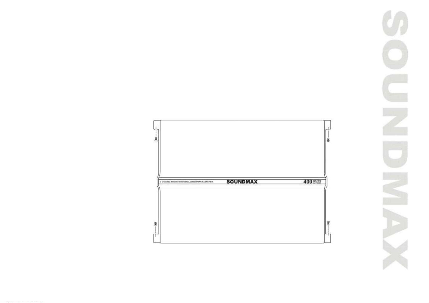
INSTALLATION DIAGRAM
Fig. 1
Page 6

6
Connections
POWER SUPPLY AND REMOTE TURN-ON OF THE AMPLIFIER
NOTE: Do not connect the plus terminals to the car battery before other connections, or it may occur
short circuit.
The gauges of power cables should be enough for the power amplifier demands at least 5.27mm2.
The + 12V DC and ground cables should be at least 6 mm2.
Firstly connect the GROUND terminal to the battery negative pole. It is very important that the
connection is fastened. Loose connection may cause malfunctions or interference noise or distortion. Dirt
residues must be carefully removed from the battery connection point.
Then connect the +12V DC power terminal via an integrated fuse to the battery plus pole. The fuse must
be located close to the battery; the length of cable from the battery positive pole to the fuse must be
50cm for safety. Install the fuse after other connections including the connection of the stereo and the
loudspeakers. Finally connect the terminal of the remote turn-on to the amplifier REM control jack. The
cable gauge of 0.75mm2 is sufficient for the amplifier REMOTE connection.
AUDIO CABLES
When installing the stereo input connection and the speaker connection, make sure the audio and the
power supply cables do not run the same side of the vehicle. This reduces crosstalk interference to the
audio cables.
LOUDSPEAKER CONNECTIONS
In normal operation mode (I.e. one loudspeaker on each Individual amplifier channel), the lowest
terminal Resistance is 2 Ohms per channel.
In bridge mode (two amplifier outputs combined), the lowest terminal resistance is 4 Ohms.
Never connect the loudspeaker negative terminals to the vehicle chassis.
Do not connect the +12V power supply to a loudspeaker output otherwise this will destroy the
amplifier terminals.
Page 7

7
Operation elements
SETTING THE INPUT AND SENSITIVITY
The regulator for input sensitivity is used to adapt amplifier for each car radio or tape deck. Turn the
volume control of your radio to central position and adjust the input-level control (2) Fig. 5, to produce
medium volume. This setting can provide sufficient power and optimum Signal to Noise (S/N) ratio.
CAUTION: Do not run the amplifier in high volume for long time, otherwise the loudspeakers will be
damaged.
LOW-PASS FILTER WITH ADJUSTABLE CROSSOVER FREQUENCY
If the unit is used as a subwoofer amplifier, turn the switch (4) to" LPF". And set proper cross-over
frequency with adjusting the control (5) to make the filter match the timbre requirement of the installed
woofer.
The crossover slope of the filter can accurately reduce the medium and high frequency ranges.
HIGH-PASS FILTER WITH ADJUSTABLE CROSS-OVER FREQUENCY
If the amplifier is used for satellite loudspeakers (mid-range/tweeter loudspeakers), turn switch (4) to
"HPF".
Set proper crossover frequency with adjusting the control (3). The frequencies only above the setting
will be amplified. This can effectively minimizes distortions caused by excessive membrane movement at
the low frequencies. And the result does not reduce the bass level when it is used for small power-supply
loudspeakers.
BASS-BOOST
Use the bass-boost switch (6) to eliminate harmonic distortion of the lower bass frequencies and weaken
the bass faction.
OUTPUTS FOR CONNECTING ADDITIONAL AMPLIFIERS
The input signal of the LOW INPUT connections L and R is directly output to the LINE OUT L and R jacks
(1).
Additional amplifiers can be connected to the LINE OUT jacks without additional T-plugs and cables.
Page 8
8
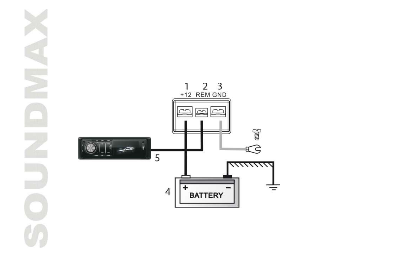
Power supply/remote turn-on connection
(1) Terminal for +12V battery voltage
(2) REM terminal for remote turn-on
(3) GND terminal for the ground, to the battery negative pole
(4) Battery
(5) Automatic antenna connection,
If your car is not equipped with an automatic antenna connection, connect this cable plus pole (+) to the
ignition lock. An on/off switch should be inserted in this case. Make sure that this switch is turned off if
the amplifier is not used.
Fig.2
Page 9

9
Stereo mode
Connect and set the amplifier as shown in Fig. 3, when the stereo has two outputs and the unit is used to
drive two loudspeakers. The high-pass filter must be activated if the amplifier drives satellite
loudspeakers.
See section HIGH-PASS FILTER WITH ADJUSTABLE CROSS-OVER FREQUENCY to catch how to regulate
the high pass filter.
Fig. 3
Page 10

10
Bridged mode
If the amplifier needs high power output to drive a subwoofer, connect and set it as shown in Fig. 4.
Fig. 4
Page 11

11
Operating elements and in/outputs
(1) CH1/CH2 inputs
(2) GAIN control
(3) High-pass filter (HPF) adjusting knob, the frequency ranges from 100Hz to 2.2kHz
(4) X-over switch (HPF/FLAT/LPF)
(5) Low-pass filter (LPF) adjusting knob, the frequency ranges from 50Hz to 250Hz
(6) Bass-boost control
(7) Indicator light (Green light means amplifier is working. Red light means self-protection mode of the
amplifier).
(8) Speaker connecting terminals
(9) Fuse
(10) +12 Power terminal, REM Remote turn-on terminal, GND Ground terminal.
Fig. 5
Page 12

12
Troubleshooting Guide
SYMPTOM
PROBABLE CAUSE
SOLUTION
No audio
Low or N.C. remote turn-on connections
Check remote turn-on voltage at amp and head
unit
Blown fuse
Replace with new fast-blow fuse
Power wires not connected
Check butt splices or solder joints;
Check ground and battery connections
Blown or non-speakers connected
Use VOM or DVM to measure speaker coil
impedance; check speaker wiring connections
Distorted audio
Input sensitivity not set properly or
damaged speaker cones
See adjustment procedure and check each step;
inspect each speaker for damage and repair or
replace suspected component
Low turn-on voltage
Refer to head unit owner’s manual
Audio level low
Mute circuits is on head unit
Check electrical system for low voltage;
Check ground connection
Audio lacks
Speakers wired with wrong polarity,
causing cancellation of bass frequencies
Check polarity of wires from amplifiers to each
speak as defined by the system design;
Check battery voltage at amplifier during
operation
External fuse
blowing
Incorrect wiring or short circuit
Refer to electrical installation and check each
installation step
Whining noise on
audio with engine
running
Amplifier is picking up alternator noise
Install a line noise filter on the head unit’s power
wire;
Check alternator routing diodes or voltage
regulator for proper operation. Check all
grounds, check battery voltage, check RCA
cables
Ticking noise on
audio with engine
running
Amplifier is peaking up radiated spark
noise
Check RCA audio cable; Install an in-line noise
filter on the head unit’s power wire, check spark
plug wires
Protection LED (right
color) light up when
the amplifier is
powered up
Incorrect impedance
Incorrect wiring or short circuit
Airflow around the amplifier is not
enough
Check if the minimum impedance is correct for
this model.
Check the speaker shots.
Check the airflow around the amplifier. More
space is required.
Before you consult this listing, make sure the vehicle’s electrical system is working properly by verifying
that other electrical items (e. g. headlights, Windows, etc.) still function correctly.
Page 13

13
Specification
MODEL
SM-SA1002
RMS Power @ 14.4 DC
2 x 100W at 4 0hms
2 x 190W at 2 0hms
1 x 360W at 4 Ohms (bridged)
Maximum power
400 W
Loudspeaker impedance (stereo)
2-8 Ohms
Frequency response
10 - 25 000 Hz
Total harmonic distortion
0.01%
Stereo separation
50 dB
Signal to Noise Ratio
98 dB
Input sensitivity
0.2V - 7V
Input impedance
10 KOhms
Low-pass filter
50-250 Hz
High-pass filter
100 Hz - 2.2 kHz
Bass boost
(0dB~12dB)
Power supply
+12V, Negative Ground
Fuse rating
30Ax1
Dimensions: WxHxL
295 x 64 x 240 mm
Weight
1.9 Kgs
Note: Specifications & design subject to change without notice for improvement. The pictures have been
done for reference and can be different from real units.
Page 14

14
ПОЗДРАВЛЯЕМ С ПРИОБРЕТЕНИЕМ НАШЕГО 2-КАНАЛЬНОГО УСИЛИТЕЛЯ МОЩНОСТИ! ЕГО
СОВЕРШЕННАЯ КОНСТРУКЦИЯ ПОЗВОЛИТ ВАМ НАСЛАЖДАТЬСЯ ВЫСОКОКАЧЕСТВЕННЫМ ЗВУКОМ С
ГАРАНТИЕЙ ОДИН ГОД. ПОЖАЛУЙСТА, ПРОЧИТАЙТЕ ВНИМАТЕЛЬНО ДАННОЕ РУКОВОДСТВО – В НЁМ
ОПИСАНЫ СВОЙСТВА И ПРАВИЛА ЭКСПЛУАТАЦИИ УСИЛИТЕЛЯ.
Содержание
СОДЕРЖАНИЕ................................................................................................................................................................. 14
ВОЗМОЖНОСТИ ............................................................................................................................................................. 15
ТРЕБОВАНИЯ БЕЗОПАСНОСТИ .................................................................................................................................. 15
УСТАНОВКА .................................................................................................................................................................... 17
ПОДКЛЮЧЕНИЕ УСИЛИТЕЛЯ...................................................................................................................................... 18
НАСТРОЙКИ .................................................................................................................................................................... 19
ПОДКЛЮЧЕНИЕ ПИТАНИЯ УСИЛИТЕЛЯ .................................................................................................................. 20
РЕЖИМ СТЕРЕО ............................................................................................................................................................. 21
МОСТОВОЙ РЕЖИМ ...................................................................................................................................................... 22
СХЕМА РЕГУЛЯТОРОВ И РАЗЪЁМОВ.......................................................................................................................... 23
ВОЗМОЖНЫЕ НЕПОЛАДКИ И ИХ УСТРАНЕНИЕ ........................................................................................................ 24
ТЕХНИЧЕСКИЕ ХАРАКТЕРИСТИКИ .............................................................................................................................. 25
Page 15

15
Возможности
Источник питания класса «AВ» с технологией MOSFET
Управление включением усилителя с головного устройства
Регулируемый ВЧ/НЧ 12 дБ/октава фильтр.
Улучшенная регулируемое усиление НЧ 0/12 дБ
Регулируемая чувствительность на входе
Мостовой режим работы
Защита от перегрузок, перегрева и коротких замыканий
Индикатор питания и защиты
Требования безопасности
Если после изучения руководства Вы по каким-либо причинам сомневаетесь, что сможете
самостоятельно установить усилитель, обратитесь в сертифицированную Сервисную Службу ведь это Ваш автомобиль!
Перед тем, как производить любые подключения, отсоедините отрицательную клемму
аккумулятора.
Устанавливайте усилитель таким образом, чтобы обеспечить его достаточную вентиляцию.
Лучше всего для этого подходят багажник, пространство под передними сидениями или задняя
стенка кабины грузовика. Вокруг усилителя должно оставаться свободное пространство не
менее 5 см.
Если усилитель крепится вертикально, воздушные потоки должны проходить вдоль пластин
радиатора охлаждения.
НИКОГДА не устанавливайте усилитель в перевёрнутом положении во избежание перегрева, в
результате которого устройство может отключиться или выйти из строя.
Не подвергайте усилитель воздействию прямого солнечного света или влаги.
Крепите усилитель к прочной твёрдой поверхности, способной удержать его при ударах, резких
торможениях или авариях.
При установке усилителя следите за тем, чтобы крепёжные винты не повредили топливный бак,
бензопровод, тормозные магистрали, проводку или другие важные узлы и коммуникации.
ЗАПРЕЩАЕТСЯ подключать усилитель проводами (силовыми и массы) сечением, меньше 5,27
мм2.
НЕ ДОПУСКАЕТСЯ работа усилителя без предохранителей. Блок предохранителей должен быть
расположен в пределах 0,5 метра от аккумулятора. Предохранитель не является электронным
устройством; он разрывает цепь при коротком замыкании, предотвращая, таким образом,
Page 16

16
возгорание проводов. Установка на аккумулятор и усилитель предохранителей с номиналами,
отличными от рекомендованных, может привести к поломке усилителя, при этом гарантийные
обязательства утрачивают силу.
Во избежание повреждения изоляции проводов, что может привести к сбоям в работе усилителя
или короткому замыканию, не устраивайте проводку вне салона автомобиля; рекомендуется
пропускать провода под ковриками или внутренней облицовкой.
Для снижения помех прокладывайте силовые и аудио кабели как можно дальше друг от друга
(например, по разным сторонам салона).
Для предотвращения повреждения изоляции проводов в местах, где они проходят через
отверстия в металлических элементах, следует устанавливать проходные изолирующие втулки.
При прокладке проводов по возможности используйте различный крепёж (зажимы, хомуты и
др.), а также оставляйте припуски, ослабляющие натяжение.
Целесообразно проверить работу усилителя перед окончательной его установкой, пока
внутренняя облицовка не установлена на место.
Если температура в салоне слишком высокая или, наоборот, низкая, усилитель может перейти в
защитный режим и отключиться. В таких случаях не включайте усилитель до тех пор, пока
окружающая температура не станет нормальной.
Усилитель может быть установлен в любом автомобиле, где есть питание 12В с отрицательной
«массой». Если вы не знаете, какой системой оснащён Ваш автомобиль, обратитесь в
сертифицированную Сервисную Службу или к квалифицированному специалисту.
ЗАПРЕЩАЕТСЯ подключать к корпусу и замыкать накоротко провода от динамиков. Эти провода
должны иметь сечение не меньше 0,832 мм2.
Усилитель должен отключаться при выключении магнитолы (источника сигнала), если она не
оснащена выходом для дистанционного управления, подключайте дистанционный выключатель
к проводу, на котором после поворота ключа в замке зажигания будет +12В. Если усилитель не
отключать, аккумулятор разрядится
Чтобы не повредить слух, не слушайте долго громкую музыку.
ДЛИТЕЛЬНОЕ ВОЗДЕЙСТВИЕ ГРОМКОГО ЗВУКА (ВЫШЕ 100 ДБ) МОЖЕТ ПРИВЕСТИ К ПОТЕРЕ СЛУХА.
МОЩНЫЕ АВТОМОБИЛЬНЫЕ АУДИОСИСТЕМЫ МОГУТ ВЫДАВАТЬ БОЛЕЕ 130 ДБ. БУДЬТЕ
БЛАГОРАЗУМНЫ!
Page 17

17
Установка
Выберите место для установки усилителя, учитывая приведенные выше требования
безопасности.
Приложите усилитель к выбранному месту и наметьте точки для сверления четырёх крепёжных
отверстий, предварительно сняв декоративные пластиковые накладки справой и с левой
стороны усилителя. Используйте карандаш с тонким стержнем для удобства разметки. Ни в
коем случае не используйте сам усилитель в качестве шаблона при сверлении, чтобы не
повредить его.
Отодвиньте усилитель, вернув на свои места декоративные накладки, и просверлите 4
отверстия диаметром 3,5мм в стальной основе и 3,0мм – в пластике или деревянной панели.
Перед окончательной установкой усилителя проверьте работу системы.
Закрепите усилитель четырьмя саморезами.
Рис. 1
Page 18

18
Подключение усилителя
ПОДКЛЮЧЕНИЕ ПИТАНИЯ УСИЛИТЕЛЯ
Внимание: Никогда не подключайте плюсовую клемму усилителя до подключения других разъёмов
и соединений, так как это может быть причиной короткого замыкания.
Толщина сечения силового кабеля для усилителя должна удовлетворять требованиям усилителя (не
менее 5.27 мм2). Кабель массы (земли) должен быть на менее 6 мм2.
Подсоедините первым кабель массы к отрицательному выходу аккумуляторной батареи. Важно,
чтобы контакт был плотный и надёжный, иначе могут возникать помехи и сбои в работе. На
контактах батареи не должно быть никаких следов грязи и пыли.
Подключите +12 B вход силового кабеля к + выходу батареи, обязательно включив в схему
предохранитель
(не менее 40 А). Предохранитель должен находиться рядом с батареей и длина кабеля между ним и
плюсом батареи должна составлять 50 см. Установить предохранитель рекомендуется после того,
как вы установили все другие подключения и соединения стерео сигнала и динамиков.
В завершении подключите управляющий кабель к соответствующему разъёму на усилителе.
Толщина кабеля должна быть не меньше 0,75 мм2.
АУДИО КАБЕЛИ
Для правильного подключения акустики и линейных входов, не прокладывайте силовые и аудио
кабели с одной стороны автомобиля, дабы избежать взаимных наводок и помех.
ПОДКЛЮЧЕНИЕ ДИНАМИКОВ
Для нормального функционирования каждого динамика, сопротивление на каждом канале должно
составлять не менее 2-х Ом.
В мостовом режиме, когда два выхода усилителя скомбинированы, сопротивление на разъёмах
должно быть не меньше 4-х Ом.
Ни в коем случае не подключайте «минус» от динамиков к корпусу автомобиля.
Ни в коем случае не подключайте питание +12В на выход на динамики, дабы избежать повреждения
разъёмов на усилителе.
Page 19

19
Настройки
Установка входной чувствительности
В усилителе предусмотрена возможность настройки чувствительности, что позволяет использовать
его с различными источниками сигнала. Установите уровень звука вашего головного устройства в
центральное положение и регулируйте уровень чувствительности (регулятор 2 на схеме 5), чтобы
получить среднее значение звука. Такая настройка обеспечит вам достаточную мощность и
оптимальное отношение сигнала к шуму.
Внимание: Ни в коем случае не используйте усилитель в режиме максимального звука, это может
разрушить динамики.
Регулировка фильтра низких частот
Если усилитель используется в качестве усилителя на сабвуфер, установите переключатель (4) в
положение “LPF”. Также установите необходимое значение переходной частоты, регулятором (5),
таким образом, установив требуемый частотный диапазон для сабвуфера. Кроссовер фильтра
позволяет отсечь диапазон средних и высоких частот.
Регулировка фильтра верхних частот
Если усилитель используется для подключения НЧ/СЧ-динамиков и твитеров, установите
переключатель (4) в положение “HPF”. Также установите необходимое значение частоты среза,
регулятором (3). Частоты находящиеся ниже установленной регулятором будут подавляться. Таким
образом, достигается эффективное снижение искажений возникающих вследствие глубоких
колебаний мембраны динамика на низких частотах. Данная схема может быть использована для
подавления инфранизких частот при подключении сабвуфера.
Усиление уровня НЧ-сигнала
Чтобы улучшить отдачу громкоговорителей на низких частотах, используйте регулятор повышения
уровня НЧ-сигнала Bass-Boost (6). Однако, делайте это аккуратно, поскольку чрезмерное усиление
баса, может стать причиной выхода из стоя громкоговорителей.
Подключение дополнительного усилителя
Входной разъём по низким частотам L и R, является линейным выходом LINE OUT L и R под RCA-
разъемы (тюльпаны) (1). Дополнительный усилитель может быть подключен к линейному выходу
основного усилителя с помощью кабеля 2xRCA-2xRCA без дополнительных переходников.
Page 20

20
Подключение питания усилителя
(1) Разъем для питания от батареи +12V
(2) Разъем дистанционного управления
(3) Разъём для кабеля от отрицательного полюса батареи
(4) Аккумуляторная батарея
(5) Провод дистанционного управления
Примечание: в случае, если ваше головное устройство не оборудовано проводом дистанционного
управления, используйте провод прикуривателя, тогда сигнал на включение усилителя должен
подаваться с использованием реле.
Важно соблюсти правило, при котором после выключения зажигания, усилитель будет выключаться
автоматически.
Рис. 2
Page 21

21
Режим стерео
Подключите усилитель, как показано на схеме 3. В этом случае усилитель управляет двумя
динамиками в стерео режиме. Для того чтобы воспользоваться фильтрами НЧ и ВЧ обратитесь к
соответствующему пункту данной инструкции.
Рис. 3
Page 22

22
Мостовой режим
Если вы хотите использовать мощность усилителя для сабвуфера, подсоедините устройство так, как
показано на рис. 4, с применением фильтра НЧ.
Рис. 4
Page 23

23
Схема регуляторов и разъёмов
(1) Низкоуровневый вход (Левый, Правый)
(2) Регулятор чувствительности
(3) Регулятор усиления ВЧ-сигнала от 100 Гц до 2.2 кГц
(4) Переключатель фильтра частот (HPF/FLAT/LPF)
(5) Регулятор усиления НЧ-сигнала от 50 Гц до 250 Гц
(6) Регулятор низких частот
(7) Световой индикатор. При включенном усилителе индикатор горит зеленым цветом. Красный
цвет означает аварийный режим.
(8) Разъемы для подключения динамиков
(9) Предохранитель
(10) Разъем +12, REM разъем дистанционного управления, GND разъем “заземления”.
Рис. 5
Page 24

24
Возможные неполадки и их устранение
Неполадка
Возможная причина
Способ устранения
Нет звука
Ненадёжно или вообще не
подсоединён провод
дистанционного отключения.
Проверьте напряжение в цепи.
Сгорел предохранитель.
Замените его.
Не подключено питание.
Проверьте клеммы аккумулятора и
электрические цепи.
Неисправны или не подключены
динамики.
Проверьте катушки динамиков и линии
подключения.
Некачественный
звук
Неправильно настроена
чувствительность.
Неисправны динамики.
Перенастройте чувствительность,
контролируя каждое действие.
Проверьте динамики и, при
необходимости, замените их.
Низкий уровень входного сигнала
Отрегулируйте уровень входного сигнала.
Тихое звучание
Неполадки на линии источника
сигнала.
Проверьте электрические цепи.
Обеднённое
звучание
Не соблюдена полярность при
подключении динамиков,
вследствие чего басы глушатся.
Проверьте полярность подключения
каждого динамика и напряжение питания
усилителя во время работы.
Перегорел
предохранитель
Неправильное подключение в
электрической цепи или КЗ.
Проверьте все электрические цепи.
Воющий звук при
включении
двигателя
Усилитель реагирует на работу
генератора.
Установите шумоподавляющий фильтр на
линию питания источника сигнала
(например, магнитолы).
Проверьте управляющие диоды и
регулятор напряжения генератора.
Проверьте все электрические цепи и
линии соединений, RCA кабели.
Характерный
тикающий звук
при включении
двигателя
Усилитель реагирует на искрение.
Проверьте RCA аудио кабели; Установите
шумоподавляющий фильтр на линию
питания источника сигнала; Проверьте, не
искрят ли электрические соединения.
При возникновении любых неполадок в работе усилителя в первую очередь проверьте его питание.
Page 25

25
Технические характеристики
Модель
SM-SA1002
Номинальная мощность @ 14.4
2 x 100 Вт на 4 Ом
2 x 190 Вт на 2 Ом
1 х 360 Вт на 4 Ом (мостовой режим)
Максимальная выходная мощность
400 Вт
Сопротивление динамиков в режиме стерео
2-8 Ом
Диапазон воспроизводимых частот
10 - 25 000 Гц
Гармонические искажения
0,01%
Разделение каналов
50 дБ
Соотношение сигнал/шум
98 дБ
Входная чувствительность
0,2 В – 7 В
Входное сопротивление
10 КОм
Фильтр низких частот
50-250 Гц
Фильтр высоких частот
100 Гц – 2.2 кГц
Усиление НЧ-сигнала
0 дБ ~ 12 дБ
Рабочее напряжение
+12В (отрицательный полюс – масса)
Номинал предохранителей, А
30Ax1
Размеры (Ш х В х Д), мм
295 x 64 x 240 мм
Масса устройства
1.9 кг
В целях улучшения конструкция и технические характеристики усилителя могут быть изменены без
предварительного уведомления.
Схемы и рисунки в данной инструкции могут отличаться от реальных параметров.
 Loading...