

Page 1

7
CONTENT
INTRODUCTION---------------------------------------------------------------------------------------2
TECHNICAL SPECIFICATIONS-------------------------------------------------------------------2
WARNING & CAUTION------------------------------------------------------------------------------2
CONFORMITY------------------------------------------------------------------------------------------2
CONTROLS &FUNCTIONS------------------------------------------------------------3
FRONT PANEL-------------------------------------------------------------------------------------------3
REAR SIDE------------------------------------------------------------------------------------------------6
INSTRUCTIONS OF FOOT CONTROL--------------------------------------------------------------7
MIDI SETTING-------------------------------------------------------------------------------------------7
OPERATING INSTRUCTIONS----------------------------------------------------------------------8
1. RUN PATTERN-------------------------------------------------------------------------------------8
2. PROGRAM------------------------------------------------------------------------------------------8
3. ASSIGN PROGRAM----------------------------------------------------------------------------8
4. PATCH SETTING--------------------------------------------------------------------------------8
5. RUN PATTERN IN CROSS MODE-------------------------------------------------------------9
6. RUN PATTERN IN LOOP CHASE MODE----------------------------------------------------9
7. DUMP BLIND------------------------------------------------------------------------------------9
8. LATCH FUNCTION-------------------------------------------------------------------------------9
9. DELETE PATTERN--------------------------------------------------------------------------------9
INITIALIZATION & MEMORY DUMP------------------------------------------------------------10
INTRODUCTION:
The SRC-173 is a 16 channel programming console with MIDI & DMX interface. The SRC-173 features
including:60 built-in patterns & 30 variable programs with 99 steps at most, MANUAUAUTO/AUDIO/TAP
SYNC/CROSS modes. Specially, the SRC-173 is incorporated with PEROM to guarantee data security. Before
operating your unit, please read this manual thoroughly and retain it for future reference.
TECHNICAL SPECIFICATIONS:
POWER INPUT---------------------------------------------------------------------------------------DC 12~20V, 250mA min
DMX OUTPUT------------------------------------------------------------------------------------------------3 Pin female XLR
AUDIO INPUT------------------------------------------------------------------------------------------------------100mV-1vpp
MIDI INTERFACE----------------------------------------------------------------------------------------5 Pin multiple socket
ACCESSORY--------------------------------------------------------------------------------------(Optional)Foot controller_1
DIMENSIONS---------------------------------------------------------------------------------------------482_177.5X72.7mm
WEIGHT-----------------------------------------------------------------------------------------------------------------------2.3kg
Page 2
7
WARNING!
To prevent fire or shock hazard, do not expose this unit to rain or moisture. Be careful not to initialize your unit
frequently, it does harm to your memory. Use recommended AC/DC adaptor
CAUTION! No user serviceable parts inside do not attempt repairs. In the event your unit should fail, contact
your local authorized dealer.
CONFORMITY: This product complies to EN 50081-1/EN 55022 pr EN 55103-1 (EMC emission) and EN
50082-1/EN 61000-4-2 pr EN 55103-2(EMC immunity).
CONTROLS & FUNCTIONS
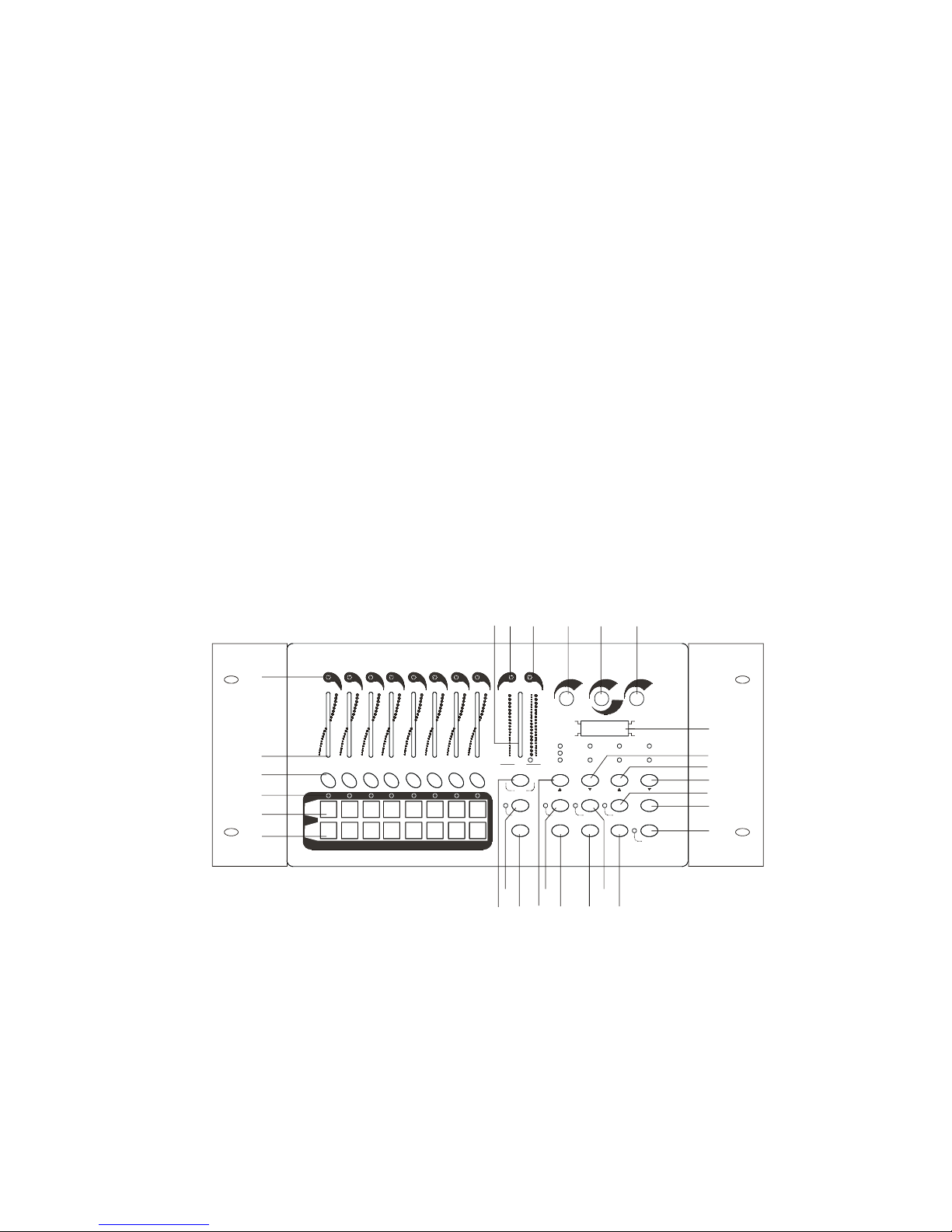
FRONT PANEL
1. Channel indicators
2. Channel fader
Controls the level in ASSIGN PROGRAM mode or the channels in MANUAL mode.
3. LATCH button(CH.9~CH.16)
It functions as ASSIGN LATCH or channel LATCH in manual mode.
4. FLASH button (CH.1~CH.16)
It functions as ASSIGN FLASH or channel FLASH in MANUAL mode.
SHIFT+FLASH button
Changes the BLIND setting in chase mode and when BLIND ENABLE indicator is lit.
5. MASTER fader
It functions as a master fader for fader 1 to fader 8 or in chase mode and CROSS FUNCTION as a master for
the pattern and the patterns are executed step by step by moving the MASTER fader.
6. M indicator
1
1
5 6 7 8 9 10
11
14
15
26
21
20
16
12
17 18 19
22 23 24 2513
1
2
4
4
3
2
10 10 10 10 10 10 10 10 10 10
0 0 0 0 0 0 0 0 0 10 0
3 4 5 6 7 8 M
MASTER LEVEL SPEED
FADE TIME
AUDIO
A
B
Tap Sync
Manual Step
Button Setup
End Step
Loop Exit
Loop Shift
Audio
Chase
Manual Step
Tap Sync
Manual
Stand By
ProgramAdd/Kill
Cross
Assign Patch Full On
PATTERN
FLASH
1-8
STEP
Fade Time Setup
Delete Program
Cross Setup
MIDI Channel
Blind
Manual
Chase
Channel Flash No Fade Time Cross Off MIDI Signal
Assign Kill
Assign Add Step Time Cross On Enable
Audio
LATCH
9-16
FLASH
9-16
9 10 11 12 13 14 15 16
Page 3

7
Indicating the MASTER status for fader 1 to fader 8.
7. A & B indicators
Indicating the MASTER status of two neighboring steps in cross mode.
8. LEVEL knob
This knob functions as a master for the pattern in chase mode.
9. SPEED/FADE TIME knob
This knob controls the chasing speed from 10 steps/second to 1 step/5 minutes and time from 0.1 second to 5
minutes in chase mode.
10. AUDIO knob
This knob controls the sensitivity of music rhythms in audio chase mode.
11. LCD
It shows the present operating mode and program options.
12. CROSS button
Press this button to enter or leave CROSS mode in chase mode and when CROSS ON indicator is lit.
13. PATTERN + button
Press to increase the left two digits by one . Pressing this button for more than one second increases the digits
quickly from present counter till the maximum and then increase from the minimum cyclically.
SHIFT + BUTTON SETUP
Pressing SHIFT + BUTTON SETUP together sets the channel fader ; LATCH button and FLASH button,
each pressing makes a new setting , and the matching indicator is lit.
14. PATTERN-button
Press to decrease the left two digits by one. Pressing this button for more than one second decreases the
digits quickly from present counter till the minimum and then decrease the digits quickly from present
counter till the maximum an then decrease from the maximum cyclically.
SHIFT + FADE TIME SETUP
Pressing SHIFT + FADE TIME SETUP sets the fade time. When NO FADE TIME indicator is lit. fade time
is disabled . If STEP TIME indicator is lit, fade time is set by the SPEED knob and is identical to the step
time.
15. STEP + button
Press to increase the right two digits by one. Pressing this button for more than one second increases the
digits quickly from present counter till the maximum and then increase from the minimum cyclically. In
chase mode, press this button to execute the pattern by one step. Pressing for more than one seconds allows
to execute the pattern by ten steps per second.
SHIFT + CROSS SETUP button
Pressing SHIFT + CROSS SETUP together sets ENABLE or DISABLE for CROSS mode. If CROSS OFF
indicator is lit, Press the CROSS button to enter or leave CROSS mode.
16. STEP-button
Press to decrease the right two digits by one. Pressing this button for more than one second decreases the
digits quickly from present counter till the minimum and then decrease from the maximum cyclically. In
chase mode, press this button to execute the pattern by one step. Pressing for more than one seconds allows
to execute the pattern by ten steps per second.
SHIFT + BLIND button
Pressing SHIFT+BLIND together sets ENABLE or DISABLE for BLIND mode. When it is BLIND mode,
the ENABLE indicator is it.
17. ADD/KILL button
Press to select ADD or KILL mode and if it is KILL mode the indicator near this button is lit. In ADD mode,
the FLASH button levels are isolate from other levels. In KILL mode and when the FLASH button levels are
turned on, the other levels are set to zero.
18. PROGRAM button
Press this button for more than one seconds to enter PROGRAM mode. the indicator close to this button is
lit, now 30 variable patterns(1~30) are ready to be programmed, each containing 99 steps at most. Press this
button to store your setting as one step. the LCD shows the next step to be programmed.
SHIFT + END STEP button
IN PROGRAM mode, pressing SHIFT + END STEP together stets the present step as the last step
19. ASSIGN button
Press this button for more than one seconds to enter ASSIGN mode. the indicator close to it is lit .In
ASSIGN mode, Press ASSIGN button first, then press FLASH button to store the present level as ASSIGN
SHIFT +DELETE PROGRAM button
In PROGRAM mode , Press SHFIT + DELETE PROGRAM together to delete present pattern.
20. PATCH button
Press this button for more than one seconds to enter or leave PATCH mode, In PATCH mode. the LCD show
the level with the left two digits and shows DMX channel NO. with the right two digits . When the left two
digits show 00, the DMX channel level is 0, if it shows FF, the DMX channel level is maximum, and if it
shows 01 to 16, the DMX channel level is 1 to 16 channel level , In MIDI CHANNEL mode, this button is
invalid.
SHIFT+MIDI AHANNEL button
Press SHIFT+MIDM CHANNEL together for more than one second to enter or leave MIDI CHAN-NEL
Page 4
7
mode, In MIDI CHANNEL mode , press STEP +or STEP-button to select desired channel. The LCD shows
CH:XX.MIDI CHANNEL lapse if the indicator close to PATCH button is lit
21. FULL ON button
Press to make 1~8 channels full intensity and STAND BY is not effective.
22. SHIFT button
This button is valid only used with other function button
23. LOOP button
In CHASE mode, press this button to enter LOOP CHASE mode and define present pattern as the 1 st
pattern run by LOOP, the LCD shows XX:LP, press this button again to add the pattern (showing XX)to the
patterns run by LOOP. Up to 100 patterns can be run by LOOP, if over 100 patterns, the LCD shows XX:FL,
if the LOOP button is not pressed within 10 seconds the LCD shows XX:CL, the present pattern is XX, press
LOOP button, the LCD turns to XX:LP, now the patterns are ready to be added to the patterns run by LOOP.
SHIFT+LOOP EXIT button
Press SHIFT+LOOP EXIT together to leave LOOP CHASE mode.
24. CHASE button
Press to enter auto chase mode, the matching point in LCD is lit, In this mode, the chasing speed is
controlled by the SPEED knob and the pattern is controlled by the LEVE knob.
SHIFT+SUDIO button
Press SHIFT+AUDIO together to enter audio chase mode .the matching point in the LCD is lit
25. TAP SYNC button
In CHASE mode, press this button to enter TAP SYNC chase mode, the matching point in the LCD is lit., In
this mode, the interval of the last two pressing on TA SYNC button is set to step time . single pressing is
invalid , To leave this mode turn the SPEED knob to enter auto chase mode.
SHIFT+MANUAL STEP button
Press SHIFT+MANUAL STEP together to enter manual chase mode. the matching point in the LCD is lit. In
this mode, press STEP+ or STEP – to execute the patterns.
26. STAND BY button
Press to enter or leave STAND BY mode. In STAND BY mode, the indicator close to this button is flashing.
Channel fader , LATCH button and the master level generate by present pattern are turned off, FLASH
button level remains.
SHIFT+MANUAL button
Press SHFIT+MANUAL together to enter MANUAL mode, the matching point it LCD is lit and the LCD
shows the MASTER fader with 000 to 100.
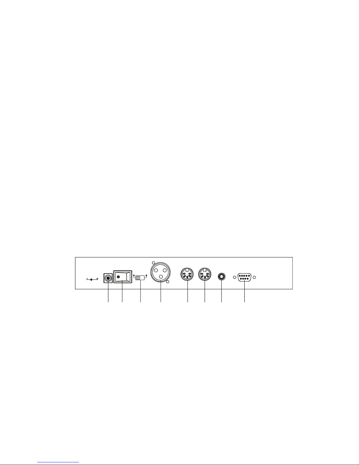
REAR SIDE
1. DC input
DC 12V~20V,250mA min, connect to AC outlet via recommended AC/DC adaptor.
2. POWER switch
Press to turn the power no/off
3. DMX polarity selector
Slide to select the polarity arrangement for DMX output.
4. DMX output
96 DMX channel output
5. MIDI THRU
Transmit MIDI data received on the MIDI IN connector.
6. MIDI IN
Receive MIDI data.
7. AUDIO line input
Line in the music rhythms ranged from 100MV to 1Vpp. If it is connected , the built-in microphone is
disabled, and when it is not connected, the microphone is enabled.
POLARITY SELECT
DC 12V~20V,
250mA min.
DC INPUT POWER DMX OUT MIDI THRU MIDI IN LINE INPUT FOOT CONTROL
ON OFF
1 2 3 4 5 6 7 8
1=Ground
2=Data 3=DATA+
1=Ground
2=Data +
3=DATA-
Page 5

7
8. FOOT CONTROL
Use to connect to foot controller for remote control.
PIN FUNCTION
1 STEP UP
2 PATTERN UP
3 STAND BY
4 FULL ON
5 COMMON
INSTRUCTIONS OF FOOT CONTROLLER
1. STAND BY button
Press to change the STAND BY status causing its indicator from flashing to off or from off to flashing.
2. FULL ON button
Press this button down, channel 1 to channel 8 are full on and not controlled by STAND BY
3. STEP UP button
In CHASE mode, press to execute the pattern by one step. pressing for more than one second would execute
the pattern by 10 steps per second.
4. PATTERN UP button
In CHASE mode, press to select pattern by plus one ,press for more than one seconds would increase the
pattern quickly till the maximum and then increase from 01.
5. CONTROL OUTPUT cable
Connect to the FOOT CONTROL located on the rear of DM-16
PIN FUNCTION
1 STEP UP
2 PATTERN UP
3 STAND BY
4 FULL ON
5 COMMON
MIDI SETTING
1. NOTE DATA
NOTE NUMBER VELOCITY FUNCTION
22-81 master level for the pattern turn on/off 1-60 patterns
82-97 channel dimmer identical to that set by FLASH1-16
99 FULL ON
101 execute the pattern by one step
102 change the STAND BY status
2. If MIDI signal disappears, 10 minutes latter the matching indicator is off and the MIDI settings are dumped.
3. To receive MIDI signal, set the MIDI channel according to the setting of MIDI settings are dumped.
4. The patterns turned on by MIDI are not controlled by LEVE knob and not showed in the LCD all turned on
patterns are executed synchronously and the terminal level is synthesized by the levels of the turned on
patterns.
OPERATING INSTRUCTIONS
1. RUN PATTERN
__Press appropriate function button(s) to select desired chasing mode from AUTO, MANUAL AUDIO AND
TAP SYNC ,the LCD shows the pattern and the step.
__Press PATTERN + or PATTER- to select desired pattern from 30 built –in patterns(31-60) and 30 variable
patterns(1-30).(If the right two digits show 00, the pattern is blank or had teen deleted)
FOOT CONTROL
12345
Page 6

7
2. FULL ON button
Press this button down, channel 1 to channel 8 are full on and not controlled by STAND BY.
3. STEP UP button
In CHASE mode, press to execute the pattern by one step, pressing for more than one second would execute the
pattern by 10 steps per second.
4. PATTERN UP button
In CHASE mode, press to select pattern by plus one, press for more than one seconds would increase the pattern
quickly till the maximum and then increase from 01.
5. CONTROL OUTPUT cable
Connect to the FOOT CONTROL located on the rear of DM-16
PIN FUNCTION
1 STEP UP
2 PATTERN UP
3 STAND BY
4 FULL ON
5 COMMON
MIDI SETTING
1. NOTE DATA
NOTE NUMBER VELOCITY FUNCTION
22-81 master level for the pattern turn on/off 1-60 patterns
82-97 channel dimmer identical to that set by FLASH 1-16
99 FULL ON
101 execute the pattern by one step
102 change the ATAND YB status
2. If MIDI signal disappears, 10 minutes latter the matching indicator is off and the MIDI settings are
dumped.
3. To receive MIDI signal. set the MIDI channel according to the setting of MIDI controller.
4. The patterns turned on by MIDI are not controlled by LEVEL knob and not showed in the LCD. all
turned on patterns are executed synchronously and the terminal level is synthesized by the levels of the
turned on patterns.
OPERATING INSTRUCTIONS
1. RUN PATTERN
__Press appropriate function button(s) to select desired chasing mode from AUTO, MANUAL. AUDIO and
TAP SYNC, the LCD shows the pattern and the step.
__Press PATTERN + or PATTERN-to select desired pattern from 30 built-in patterns(31-60) and 30 variable
patterns(1-30).(If the right two digits show 00, the pattern is blank or had been deleted.)
2. PROGRAM
Press PROGRAM button for more than one seconds to enter PROGRAM mode, the matching indicator is lit.
Press PATTERN+ to select desired pattern, Make a setting by means of fader 1 to fader 8 and LATCH button
and press PROGRAM button once to store the setting as a new step. Make anew setting and press RPGOARM
once again. If you have entered all steps press SHIFT + ENDSTEP button together to define the last step.
For example, make a setting on the 11th pattern so that ch.1 to ch.16 to be full on is sequence.
__Press PROGRAM button for more than one seconds to enter PROGRAM mode, the matching indicator is
lit.
__Press PATTERN+ or PATTERN- and STEP+ or STEP- till the LCD shows 11:01
__Slide the fader 1 to up position and the other faders to down position, press LATCH 9-16 buttons to turn
all matching indicator off. After this setting press PROGRAM button once, now the LCD would show 11:02
__Slide the fade 2 to up position and the other faders to down position, press LATCH 9-16 to turn all
matching indicator off After this setting, press PROGRAM button once again, now the LCD would show 11:03
__Follow your setting as specified by _. And _ till the LCD shows 11:09 Slide all the fader to down
Position and press LATCH 9-16 to turn channel 9 indicator on and the other indicators off Press PROGRAM
button once, the LCD shows 11:10
__Continue your setting till the LCD shows 11:17, now press STEP-button to alert 11:17 to 11:16
__Press SHIFT+END STEP to define the 16th step to the last step. now the pattern is complete.
3. ASSIGN PROGRAM
There are 16 ASSIGN for the levels set by fader 1 to fader 8 and LATCH 9-16 buttons.
For example. to assign CH.1 to CH.9 full on and CH.10 to CH.16 blackout to FLASH 1 button, you should
follow the steps.
__Press ASSIGN button for more than one seconds to enter ASSIGN PROGRAM mode, the matching
indicator is lit.
Page 7

7
__Slide fade 1 to fade 8 to up position, press LATCH 9 button to turn channel 9 indicator on.
__Press ASSIGN button first. Then press FLASH 1 button, all channel indicators would flash three times
,now ASSIGN 1 is complete.
4. PATCH SETTING
In PATCH mode, you could allocate easily the outgoing DMX channels to your light fixtures.
For example. to allocate 1-16 DMX channels to 16-1 channels, please proceed as follows.
__Press PATCH button for more than one second to enter PATCH mode. the matching indicator is lit. Press
STEP+OR step –till the LCD shows 01 in the right two digits.
__Press PATTERN+ or PATTER- till the LCD shows 16 in the left two digits. now the 1st DMX channel is
relocated to the level of the 16th channel.
__Press STEP+, the LCD shows 02 in the right side, press PATTER-, the LCD shows 15 in the left side,
now the 2nd DMX channel is relocated to the level of the 15th channel.
__Follow the settings as specified by _. Till the 16th DMX channel is relocated to the level of the 1st
channel. Press PATCH button for more than one second to leave PATCH mode. the matching indicator is off.
5. RUN PATTERN IN CROSS MODE
In CROSS mode, the patterns are executed step by step by sliding the MASTER fader up and down repeatedly.
__In CHASE mode, press SHIFT+CROSS SETUP, the CROSS ON indicator is lit.
__Slide the MASTER fader to top position, press CROSS button to enter CROSS mode, the A indicator is
lit.
__Press PATTERN+ or PATTERN- till the LCD shows 11:01.
__Turn the LEVEL knob to maximum, now the A indicator is full.
__Slide the MASTER fader from top to bottom position, the pattern to be executed by one step and the step
counter to be increased by one(shows 11:02), now the channel 1 indicator is full and A is off, B is full . Slide
the MASTER fader up, the B indicator is decreased and the B indicator is increased in intensity. the channel 2
indicator is and channel 1 indicator is decreased in intensity. When the MASTER fader is top position, the B
indicator is off and the A indicator is full, the channel 2 indicator is full and the channel 1 is off, the step
counter is increased by one (shows 11:03).
__Repeat these settings to execute the pattern step by step.
6. RUN PATTERN IN LOOP CHASE MODE
In LOOP CHASE mode, select the patterns to run them in sequence and in the periodic cycle.
For example, run the 31st, 41st and 51st pattern is LOOP CHASE mode.
__Press CHASE button to enter CHASE mode.
__Press PATTERN+ or PATTERN- till the LCD shows 31: XX.
__Press LOOP button, the LCD turns to 31: LP.
__Press PATTERN+ till 41: XX and then press LOOP button.
__Press PATTERN+ till 51: XX and then press LOOP button.
__The 31st, 41st and 51st patterns are executed in sequence and cyclically for 10 seconds, then the pattern
shown in the LCD is executed.
7. DUMP BLIND
Enable or disable CHASE mode to dump BLIND.
8. LATCH FUNCTION
The levels of LATCH buttons are independent from FADE TIME, and when ADD/KILL indicator is lit it
doesn’t impact with the levels of the channel faders.
9. DELETE PATTERN
In PROGRAM mode, press SHIFT+DELETE PROGRAM to delete present pattern, the deleted pattern
wouldn’t be executed, once the deleted is alerted to be stored, it would be executable again.
INITIALIZATION & MEMORY DUMP
Press SHIFT button first, and then press LATCH 9, LATCH 13, . LATCH 10, LATCH 14, LATCH 11, LATCH
15, LATCH 12 and LATCH 16 in sequence, now release the SHIFT button, several seconds later, it is
initialized to the default mode(manual mode).
CAUTION!
This operation is harmful to the memory (PEROM), please be careful not to use it frequently.
 Loading...