

Page 1
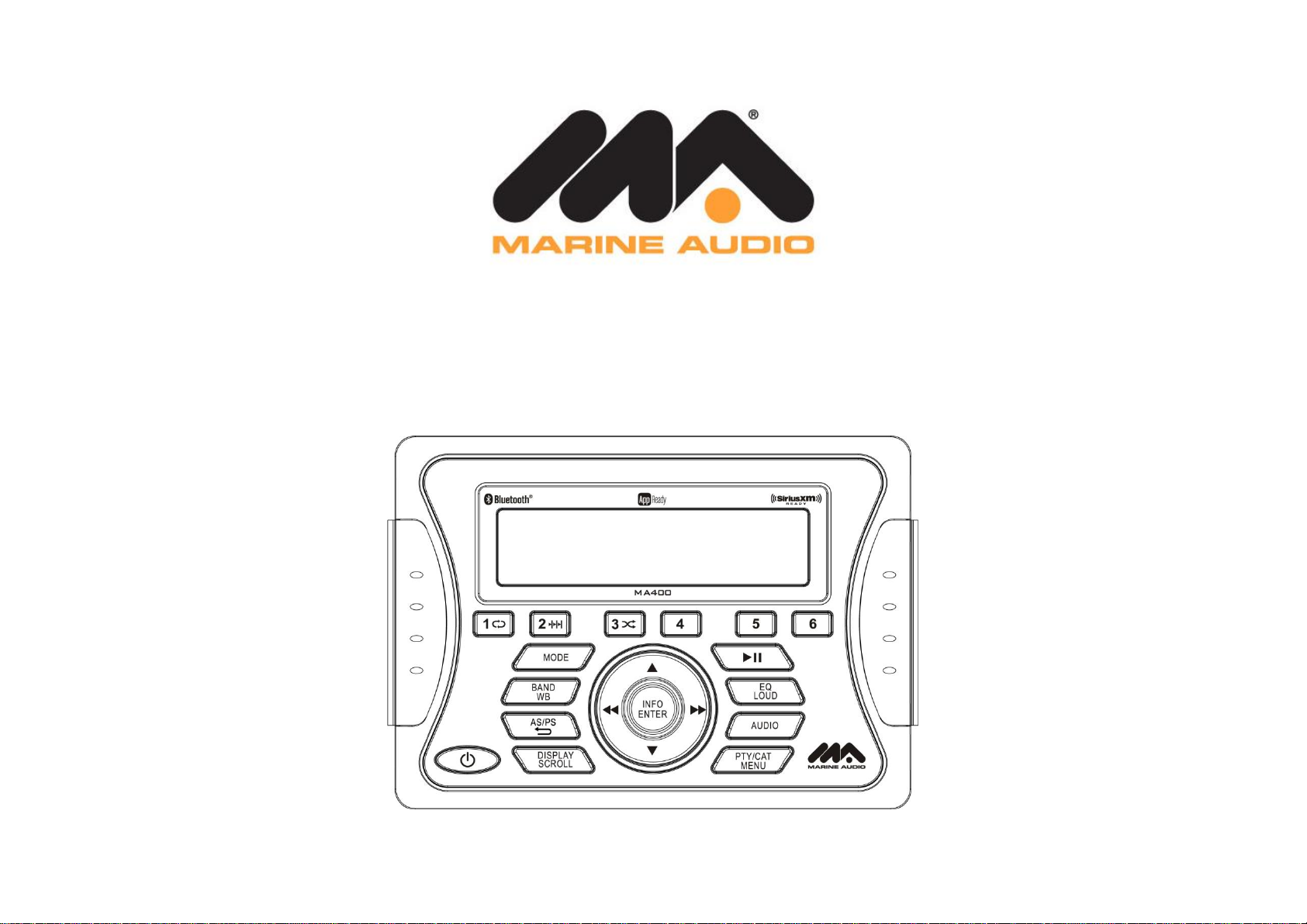
MA400
MARINE AUDIO SYSTEM
Installation and Operation Manual
Page 2

MA400
CONTENTS
Introduction ............................................................................................................................... 2
Safety Information .................................................................................................................... 3
Installation ................................................................................................................................ 4
Wiring ....................................................................................................................................... 6
Basic Operation ........................................................................................................................ 7
Tuner Operation........................................................................................................................ 9
MP3/USB Operation ................................................................................................................ 11
SIRIUSXM Radio Operation .................................................................................................... 12
iPod® Operation ...................................................................................................................... 16
Bluetooth Operation ................................................................................................................ 17
APP Operation ........................................................................................................................ 18
Care and Maintenance ........................................................................................................... 19
Troubleshooting ...................................................................................................................... 19
Specifications ......................................................................................................................... 20
Copyrights and Trademarks
All related marks and logos are trademarks of Sirius XM Radio Inc. All rights reserved.
“Made for iPod” and “Made for iPhone” mean that an electronic accessory has been designed to
connect specifically to iPod or iPhone respectively, and has been certified by the developer to
meet Apple performance standards. Apple is not responsible for the operation of this device or
its compliance with safety and regulatory standards. Please note that the use of this accessory
with iPod or iPhone may affect wireless performance.
© Copyright 2015 ASA Electronics, LLC PATENT PENDING
1
Page 3

MA400
INTRODUCTION
System Features
Features of Marine Audio MA400 mobile audio system include:
Full Dot Matrix LCD
AM/FM Tuner with 30 Presets (12AM, 18FM)
RBDS (Radio Broadcast Data Service) with PTY Search
SiriusXM-Ready (SiriusXM Connect Vehicle tuner and subscription sold separately)
USB Playback of MP3 and WMA files
iPod Ready (USB Interface)
Weatherband Tuner with SAME Technology
Mute
Bluetooth (Supports A2DP, AVRCP and ID3)
APP Ready
Pre-set Equalizer – 5 settings (User, Flat, Pop, Classical, Rock)
Electronic Bass, Treble, Balance and Fader Controls
Output Power 50W x 4
4-Channel Pre-amp Line Level Outputs (Front & Rear RCA)
2 Wire Power Supply
Auxiliary Audio Input (RCA)
Content List
Tuner Amplifier Module
Wired Commander
Wired Commander Cover
10’ Wired Commander Extension Cable
Power Harness
Stainless-steel tapping screws (4)
Quick Reference Guide
2
Page 4

MA400
SAFETY INFORMATION
When Boating
Keep the volume level low enough to be aware of your surroundings.
Protect from Water
Do not submerge or expose the product directly to water, as this can cause electrical shorts, fire
or other damage
Protect from High Temperatures
Exposure to direct sunlight for an extended period of time can produce very high temperatures
inside your vessel. Give the interior a chance to cool down before starting playback.
Do not mount radio with close proximity of engine compartment.
Use the Proper Power Supply
This product is designed to operate with a 12 volt DC negative ground battery system.
WARNING:
DO NOT OPEN, DISASSEMBLE OR ALTER THE UNIT IN ANYWAY. Doing so may result
in fire, electric shock or product damage.
USE THE CORRECT AMPERE RATING WHEN REPLACING FUSE. Failure to do so may
result in fire, electric shock or product damage.
DO NOT INSTALL IN LOCATIONS THAT MIGHT HINDER VEHICLE OPERATION. Doing
so may obstruct vision or hamper movement which can result in a serious accident.
INSTALL THE WIRING SO THAT IT IS NOT CRIMPED OR PINCHED BY SCREWS OR
SHARP METAL EDGES. Route the cables away from moving parts or sharp pointed
edges. This will prevent crimping and damage to the wiring. If the wiring must pass
through a metal hole, be sure to use a rubber grommet to prevent the wire’s insulation
from being cut by the metal edge of the hole. It is also recommended to apply sealing
caulk to any opening that may potentially allow water to enter.
Be sure to choose a location that is flat and has clearance above the unit to prevent any
damage, as well as allow for ventilation
Before drilling any holes, carefully inspect the area underneath and behind the mounting
surface where the devices will be mounted to make sure it will not interfere with existing
wires, fuel lines, the fuel tank or any other objects that could be damaged.
Always disconnect the vehicle negative battery terminal to prevent accidental shorting
during installation.
3
Page 5
MA400
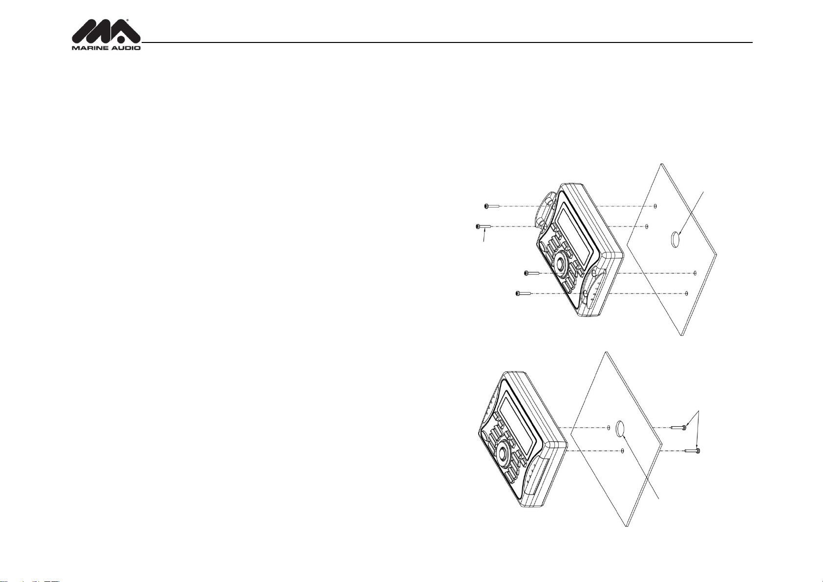
7/8” HOLE IS REQUIRED
M4 MOUNTING SCREWS (4-PCS)
MINIMUM SCREW LENGTH 1 1/2”
M5 x 8 SCREWS REQUIRED
7/8” HOLE IS REQUIRED
INSTALLATION
Before you Begin
Before you begin, always disconnect the battery negative terminal.
Important Notes
Before final installation, test the wiring connections to make sure the unit is connected
properly and the system works.
Use only the parts included with the unit to ensure proper installation. The use of
unauthorized parts can cause malfunctions.
Consult with your nearest dealer prior if installation required the drilling of holes or other
modifications to your vessel.
Install the unit where it does not interfere with driving and cannot injure passengers if there
is a sudden or emergency stop.
Avoid installing the unit where it will be subject to high temperatures from direct sunlight,
hot air, or from a heater, or where it would be subject to excessive dust, dirt or vibration.
Wired Commander Mounting
1. Choose a mounting area for the wired commander that is clean and flat, allowing the rear
gasket to fully seal to the mounting surface
2. Secure the wired commander using either of the recommended mounting methods
detailed in the diagrams below.
FOR CABLE
FOR MOUNTING
MAXIMUM SCREW DEPTH IN
COMMANDER 1/4”
FOR CABLE
4
Page 6
MA400
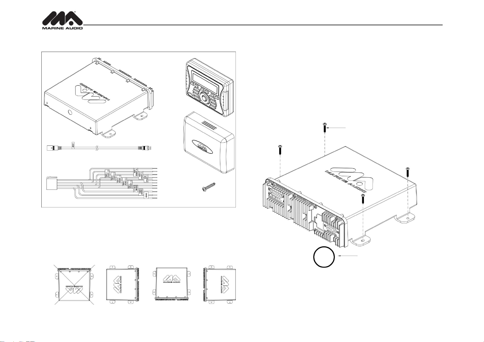
1 3/4” HOLE REQUIRED FOR CABLE/CONNECTOR
STAINLESS STEEL #8 SCREWS REQUIRED
WITH MINIMUM LENGTH OF 1”
1/8” PILOT HOLES FOR SUPPLIED SELF-STARTING SCREWS
.180 PILOT HOLES WHEN USING THREADED MACHINE SCREWS
TUNER AMPLIFIER
MODULE
WIRED
COMMANDER
WIRED
COMMANDER
COVER
POWER HARNESS
10 FOOT WIRED COMMANDER EXTENSION CABLE
STAINLESS
STEEL TAPPING
SCREW (x4)
Hardware Kit Contents
Tuner/Amplifier Mounting
1. Choose a mounting area for the tuner/amplifier module that will provide plenty of
ventilation to prevent the amplifier from overheating. The tuner/amplifier module can be
mounted in the horizontal or vertical position. Please note that when mounting in vertical
position, do not mount with the harness exit points facing straight up, as water can collect
around the chassis in these areas.
2. Using the shortest length of the recommended size screws possible, mount the
tuner/amplifier as detailed in the diagram on the right.
3. Route the tuner/amplifier harness and cable throughout the vessel as required. Keep
some slack in the harness/cables so it won't be too tight, as this can cause damage to the
wires.
4. Follow the wiring diagram carefully and make certain all connections are secure and
insulated with crimp connectors or electrical tape to ensure proper operation.
5. After completing the wiring connections, reconnect the negative terminal of the battery
and turn the unit on to confirm operation (vessel accessory switch must be on). If the unit
does not operate, disconnect battery, recheck all wiring and refer to the trouble-shooting
guide located in the back of the manual.
Reconnect Battery
When wiring is completed, reconnect the battery negative terminal.
5
Page 7
MA400
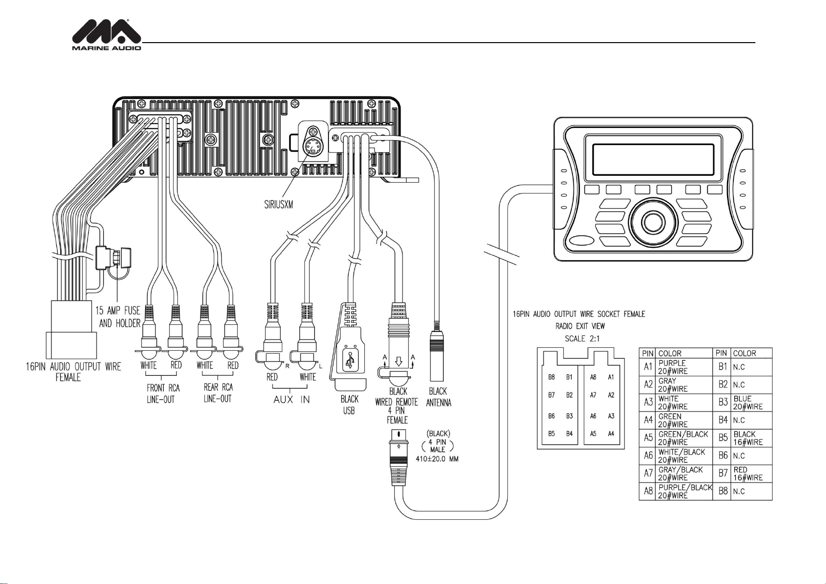
TUNER/AMP MODULE
WIRED COMMANDER
WIRING
6
Page 8
MA400
RESET
BASIC OPERATION
Power On/Off
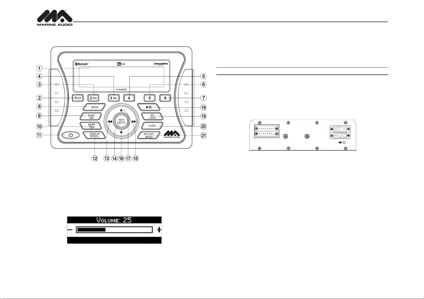
Press the POWER button (11) to turn the unit on. The unit will resume at the last mode (Tuner,
Aux, etc.).
Volume Control
To increase the volume, press the ▲ button (17). To decrease the volume, press the ▼button
(16). The maximum volume setting is “40”. While adjusting the volume, the LCD displays a bar
graph and numerical representation of the level.
Mute
Press the ►║ button (18) to mute the audio output. Press ►║again to restore the audio output
to the previous level.
Mode
Press the MODE button (8) on the control panel to select a different mode of operation, as
indicated on the display panel. Available modes include Tuner (AM/FM), SiriusXM, iPod/USB,
Auxiliary and Bluetooth Audio.
NOTE: SiriusXM and iPod mode will be skipped if the module/device is not installed.
Reset
The reset button should be activated for the following reasons:
initial installation of the unit when all wiring is completed
function buttons do not operate
error symbol on the display
Use a ball point pen or thin metal object to press the RESET button located on the tuner box.
You can recover factory default settings using the RESET function located on the system menu.
With “YES” flashing, press the MODE button (8) to activate.
Audio Menu
Press the AUDIO button (20) on the control panel to access the audio menu. You can navigate
through the audio menu items by pressing the AUDIO button repeatedly. Once the desired menu
item appears on the display, adjust that option by pressing one of the ▲/▼ buttons (16, 17)
within 5 seconds. The unit will automatically exit the audio menu after five seconds of inactivity.
The following menu items can be adjusted.
Bass Level
Use the ▲/▼ buttons to adjust the Bass level range from “-6” to “+6”.
Treble Level
Use the ▲/▼ buttons to adjust the Treble level range from “-6” to “+6”.
Balance
Use the ▲/▼ buttons to adjust the Balance between the left and right speakers from “L12” (full
left) to “R12” (full right).
Fader
Use the ▲/▼ buttons to adjust the Fader between the rear and front speakers from “R12” (full
rear) to “F12” (full front).
7
Page 9
MA400
System Menu
1. Press and hold the PTY/CAT/MENU button (21) for more than 2 seconds to enter the
system menu. The first menu item, “Key Beep”, will appear on the display.
2. Press ▲/▼ buttons (17, 16) repeatedly to navigate the system menu.
3. Press the INFO/ENTER button (14) to adjust the highlighted menu item.
4. Press the PTY/CAT/MENU button to exit the system menu.
The following items can be adjusted:
Key Beep (Click/ Beep / Off): Turn the audible beep On/Off (heard when functions/buttons
are selected).
LCD Backlight (1-10): Adjust LCD brightness.
LCD Contrast (1-10): Adjust LCD contrast.
Button Backlight (1-10)
Tuning Region (USA / EUROPE): Set frequency spacing for various regions.
Bluetooth Setup (Sub Menu, only accessible in Bluetooth mode)
BT ON/OFF: Choose “BT ON” or “BT OFF”
BT PAIR (ON/OFF): Choose “YES” to automatically pair a previously paired device
BT DEVICE (Lock/Unlock, Disconnected/Connect, Delete): View, lock and delete
from a list of previously paired mobile devices.
SXM Satellite Radio (only appear when SiriusXM tuner is connected and in SiriusXM
mode)
Set Lock Code: _ _ _ _
Locked Channels: List of Channels (Locked / Unlocked)
SXi software Version
Battery Alarm (Off / On): When On, if the battery supply voltage drops below 10.8V,
indicating a possible problem with the vessel’s battery charging system, the radio will
issue a low battery display warning and an audio beep once per minute. The warning and
sound will continue until the unit is turned off or the voltage is restored to more than 10.8
Volts
Battery Auto-Off (Off / On)
Reset To Defaults <ENTER>: Press the INFO/ENTER button (14) to return the MA400 to
factory default set up values.
Loudness
Press and hold the EQ/LOUD button (19) to toggle loudness on/off. When listening to music at
low volumes, this feature will boost the bass and treble ranges to compensate for the
characteristics of human hearing.
Auxiliary Input
To access an auxiliary device:
1. Connect a portable audio player to the AUX IN cables on the back of the radio.
2. Press the MODE button (8) to select “Auxiliary” mode.
3. Press MODE again to exit “Auxiliary” mode and access another mode.
Liquid Crystal Display (LCD)
The current frequency and activated functions are shown on the LCD panel (1).
NOTE: LCD panels may take longer to respond when subjected to cold temperatures for
an extended period of time. In addition, the visibility of the numbers on the LCD may
decrease slightly. The LCD display will return to normal when the temperature increases
to a moderate range.
Scroll
When the information is too long to be displayed on the LCD, press and hold the DISP/SCROLL
button (12) to view the entire title. The information will scroll twice and then return to abbreviated
text.
Equalizer
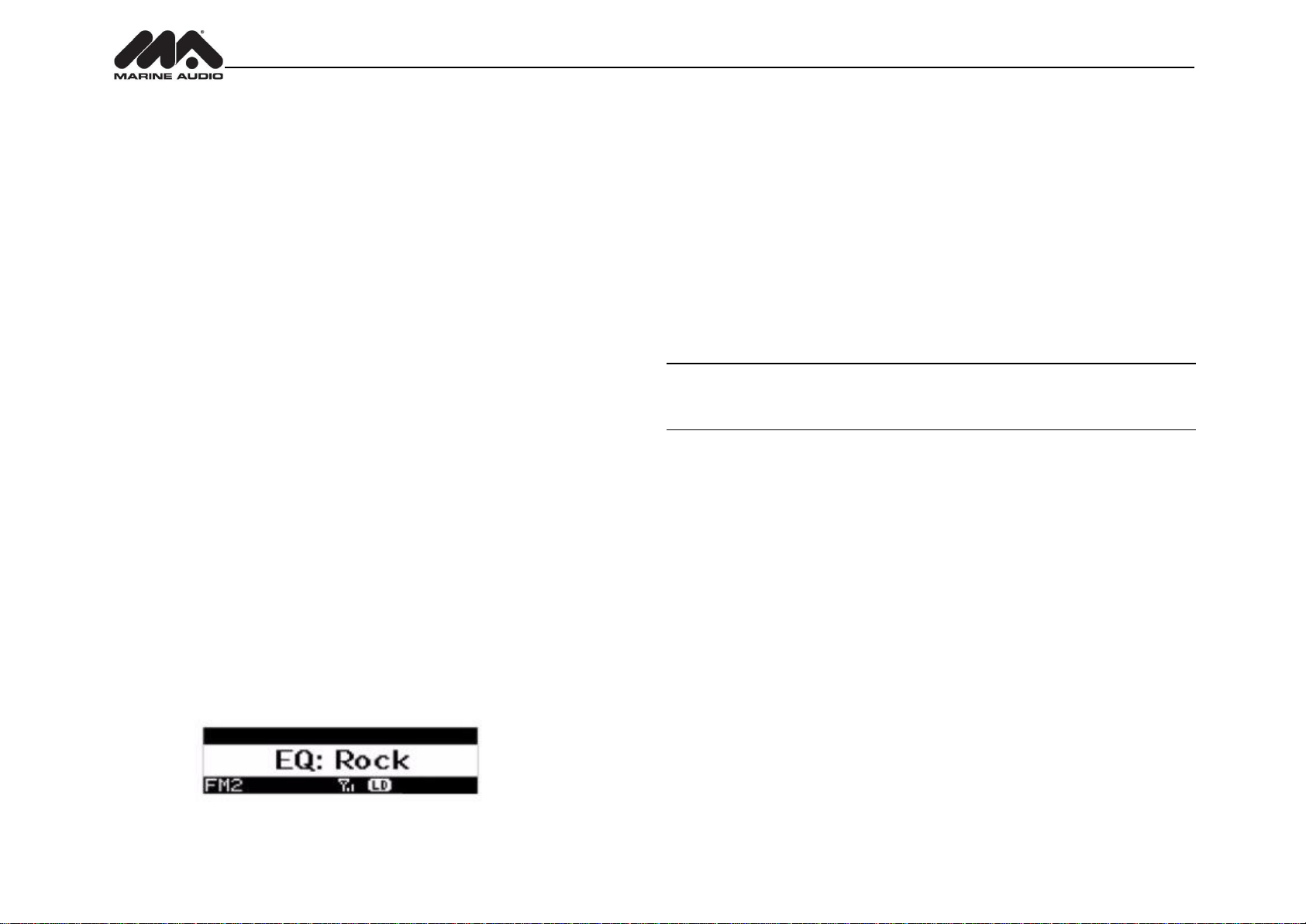
Press the EQ/LOUD button (19) to choose one of the following pre-defined bass and treble
curves: USER > FLAT > ROCK > CLASSICAL > POP.
8
Page 10
MA400
TUNER OPERATION
Select a Band
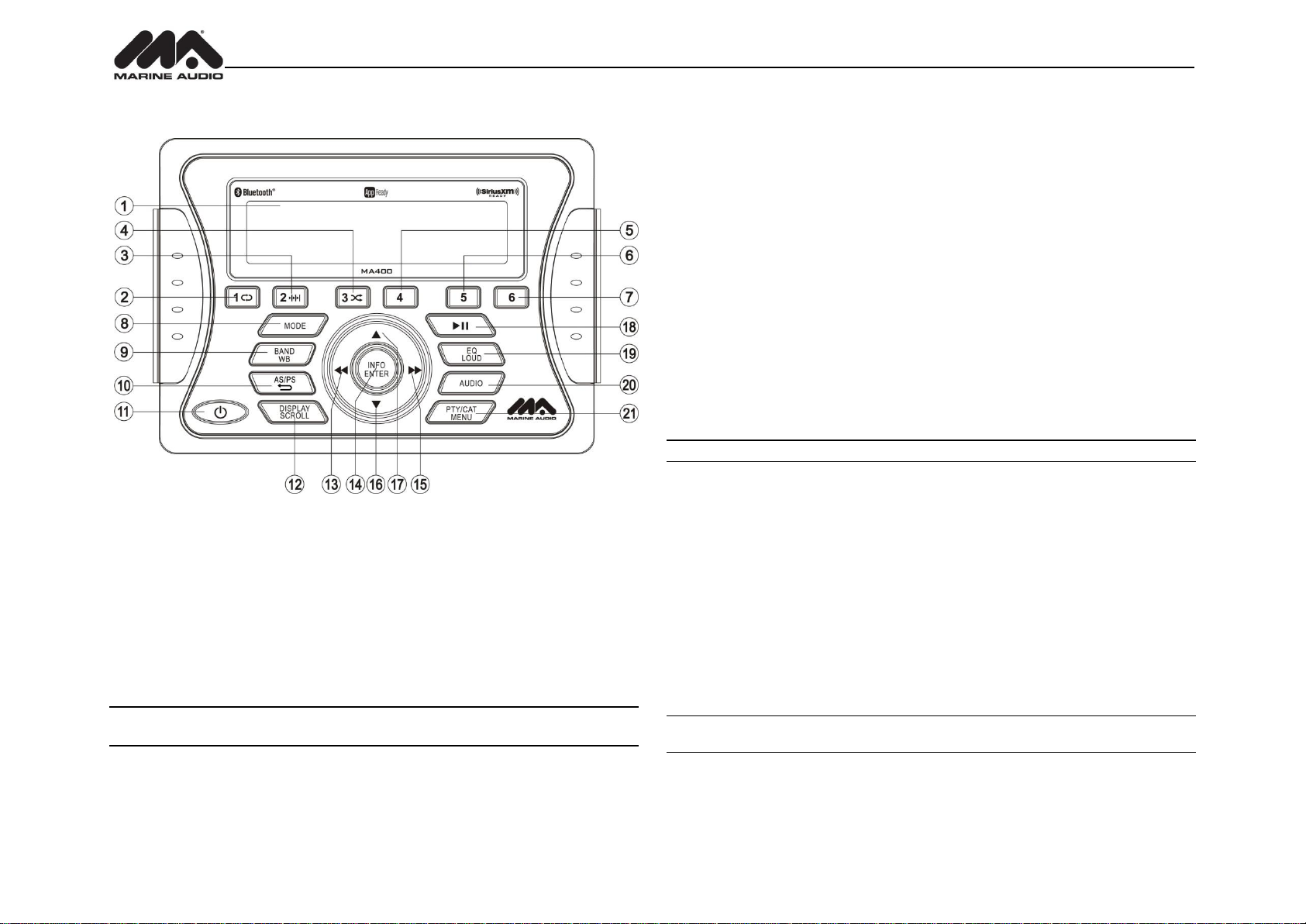
Press the MODE button (8) to change between the FM and AM bands.
Press and hold the MODE button to access the Weatherband (WB).
Manual Tuning
Press the ►►/ ◄◄ buttons (15, 13) to seek stations up/down step by step.
Auto Seek Tuning
Press and hold the ►►/ ◄◄ buttons (15, 13) to automatically seek the next or previous strong
station.
NOTE: Seek tuning is not available for weather band channels. Use the up or down tuning
buttons to manually select any of the seven available weather band channels.
Preset Stations
Six numbered preset buttons store and recall stations for each band.
Store a Station
Select a band (if needed), then select a station. Press and hold a 1-6 preset button for two
seconds. The present number will spear in the display.
Recall a Station
Select a band (if needed). Press a 1-6 preset button to select the corresponding stored station.
Automatically Store / Preset Scan (AS/PS)
Automatically Store
Select an AM or FM band. Press and hold the AS/PS button (10) for more than 2 seconds to
automatically select the 18 strongest stations (12 for AM) in your area. “Storing Presets” appears
on the screen and the new stations replace any stations already stored.
Preset Scan
Select a band. Press AS/PS button (10) to scan stations stored in the current band. The unit will
pause for 5 seconds at each preset station. Press AS/PS again to stop scanning when the
desired station is reached.
RBDS Operation
This unit is equipped to display RBDS (Radio Broadcast Data Service) information when
broadcast by the radio station.
NOTE: Radio stations broadcasting RBDS may not be available in your listening area.
In FM radio mode, press the PTY/CAT/MENU button (21) to access the PTY menu and choose
from the following Program Type (PTY) options: ANY / News / Information / Sports / Talk / Rock /
Classic Rock / Adult Hits / Soft Rock / Top 40 / Country / Oldies / Soft / Nostalgia / Jazz /
Classical / Rhythm and Blues / Soft Rhythm & Blues / Foreign Language / Religious Music /
Religious Talk / Personality / Public /College / Weather / Emergency Test / EMERGENCY!
To search for stations in a PTY category:
1. Press the PTY/CAT/MENU button (21) to view the current PTY category.
2. Press the ►►/ ◄◄ buttons (15, 13) to move through the list of available categories and
select the program type you wish to search.
3. After selecting the desired PTY, press the INFO/ENTER button (14) to search the band for
broadcasts of this type. “PTY Search” is displayed while the tuner is searching.
NOTE: Performing a PTY search on “ANY” will Seek Tune and stop on any station
broadcasting RBDS, regardless of the program type.
9
Page 11
MA400
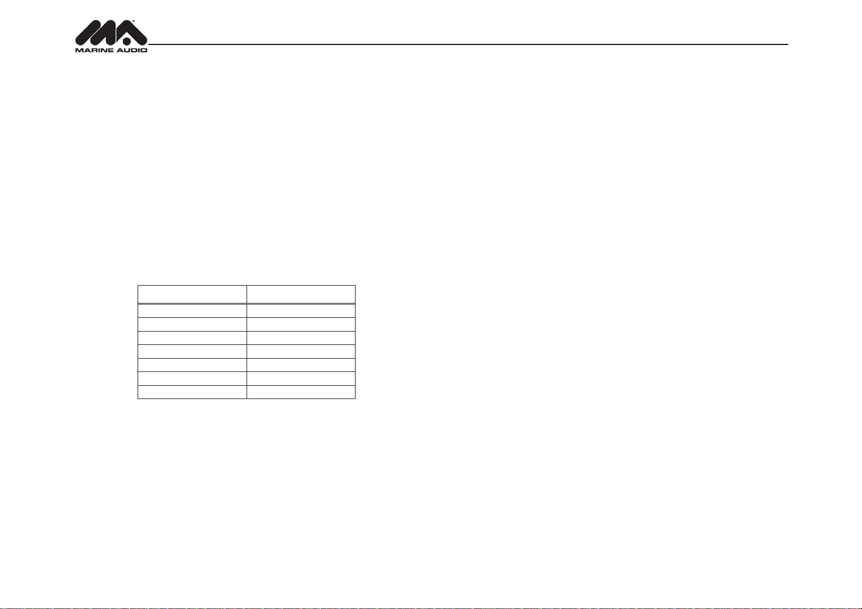
Table 1: WB Frequencies
Frequency (MHz)
Preset
162.400
2
162.425
4
162.450
5
162.475
3
162.500
6
162.525
-
162.550
1
Weather Band Operation
What is the NOAA Weather Radio/Weatheradio Canada?
NOAA (National Oceanic and Atmospheric Administration) is a nationwide system that
broadcasts local weather emergency information 24 hours a day via the National Weather
Service (NWS) network. The U.S. network has more than 530 stations covering the 50 states as
well as the adjacent coastal waters, Puerto Rico, the U.S. Virgin Islands and the U.S. Pacific
Territories. Each local area has its own transmitting station and there are a total of seven
broadcasting frequencies used. A similar system is available in Canada under the Weatheradio
Canada service administered by Environment Canada.
Tuning to Weatherband
Press and hold the BAND/WB button (9) to access the Weatherband. The indication "WB" will
appear on the display panel, along with the current number and channel indication: "WB-1",
WB-2", "WB-3", "WB-4", "WB-5", "WB-6" or "WB-7". The seven frequencies are shown in the
following table:
Is it possible I won't receive any stations?
Depending on where you are located, there is a possibility you will receive only a very weak
signal or none at all. Also, similar to AM and FM signals, weatherband signals are subject to
surrounding conditions, weather, obstructions of the signal by hills or mountains, etc.
The above table also shows which preset button will access the frequency. Note that one
frequency cannot be accessed using a preset button. The frequency can only be reached using
the tuning controls.
Use the ►►/ ◄◄ buttons (15, 13) or the preset buttons to tune to each of the seven channels
until you find the weatherband station broadcasting in your area.
How many stations can I expect to receive?
Since the broadcasts are local weather and information, the transmission power is usually very
low (much less than standard AM or FM stations) so you will usually receive only one station
unless you are on the edge of two or more broadcast signals. The most you will receive will be
two or three, and that is rare.
10
Page 12
MA400
MP3/USB OPERATION
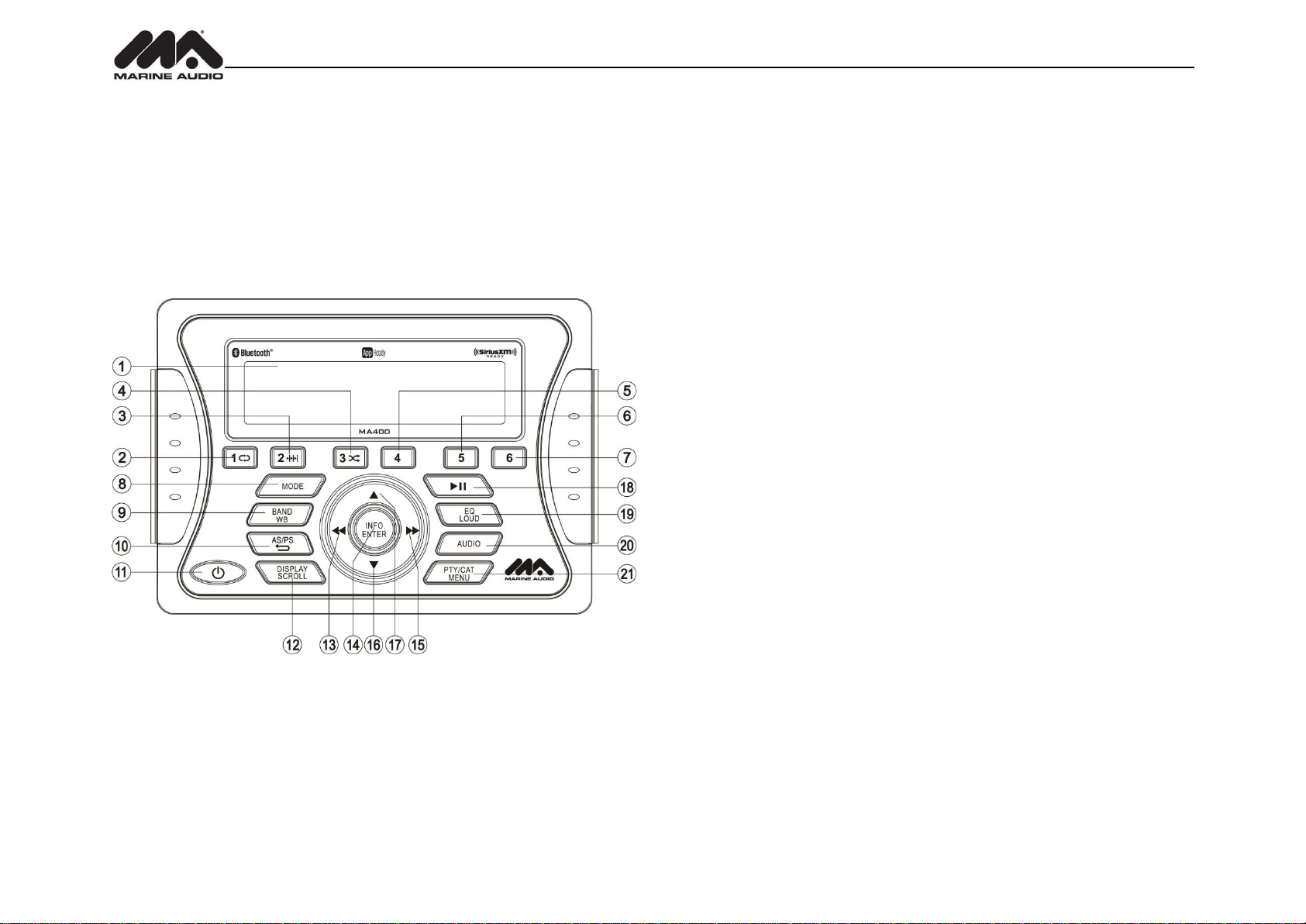
If the user connects a USB mass storage device, the radio automatically powers on, if necessary,
and switches to digital file playback mode and selects that physical media. Changing modes or
turning off the radio pauses playback. Playback will resume exactly where paused when
returning to digital file playback mode.
Inserting a USB Device
The wired USB connector is at the rear of the radio. Insert a USB device to automatically access
USB mode and begin playback.
Controlling File Playback
Accessing USB Mode
Press the MODE button (8) to select USB mode. USB mode will not be selectable unless a USB
device is connected.
Selecting Files
Press the SEEK >>| (15) or SEEK \<< button (13) to advance to the next track/ file in the current
folder. The selected track number will appear on the display. Press and hold the ►►or ◄◄
button to fast forward or fast reverse. Playback resumes when the button is released.
Play/Pause
Press the ►║button (18) to suspend playback. “Pause” is displayed on the screen.
Press the ►║ button again to resume play.
Repeat Play
Press the 1 button (2) during disc play to repeat the current track.
Press 1 again to stop repeat play.
Previewing Tracks
Press the 2 button (3) to play the first 10 seconds of each track in the current folder sequentially.
Press 2 again to stop Intro Scan and resume normal play at the current track.
Random Play
Press the 3 button (4) during disc play to play all tracks in the current folder in random, shuffled
order.
Press 3 again to stop random play.
Folder Navigation (MP3 Only)
Press the PTY/CAT/MENU button (21) to view a list of all songs in the current folder.
Press the PTY/CAT/MENU button again to navigate up through the file structure.
Press the ▲and ▼(16, 17) buttons to navigate the list.
Press the INFO/ENTER button (14) to play the highlighted song or view files in the selected
folder. Continue pressing INFO/ENTER until the desired file is selected
The unit will automatically exit the folder navigation menu after 5 seconds of inactivity.
MP3 Specifications
Notes on MP3 Playback
Any directory that does not include an MP3 file is skipped
Maximum number of folders: 512 (including skipped directories)
Maximum number of folder levels: 12
Maximum number of MP3 files: 999
Maximum number of characters for MP3 file name and folder name: 32
Maximum number of Characters of ID3 Tag:
ID3 Tag version 1.0: 32
ID3 Tag version 2.x: 32
File Playing Order
Files will be continually played sequentially within the current folder. To play songs in another
folder, press the PTY/CAT/MENU button (21) twice to move up a folder level. Press the ▲(17)
and ▲(16) buttons to navigate the list and then press the INFO/ENTER button (14) to access
the selected song or folder.
You can set the order in which MP3/WMA are to be played by storing them with their file names
beginning with play sequence numbers such as "01" to "99".
11
Page 13
MA400
SIRIUSXM RADIO OPERATION
About SiriusXM
Sirius, XM and all related marks and logos are trademarks of Sirius XM Radio Inc. and its
subsidiaries. Visit www.siriusxm.com/xmlineup for updates. All programming/channel lineup/ XM
service subject to change or preemption. All other marks and logos are the property of their
respective owners. All rights reserved.
NOTE: The SiriusXM Satellite Radio controls on this unit are available only when an
optional SiriusXM Connect Vehicle Tuner is connected.
Selecting a Band
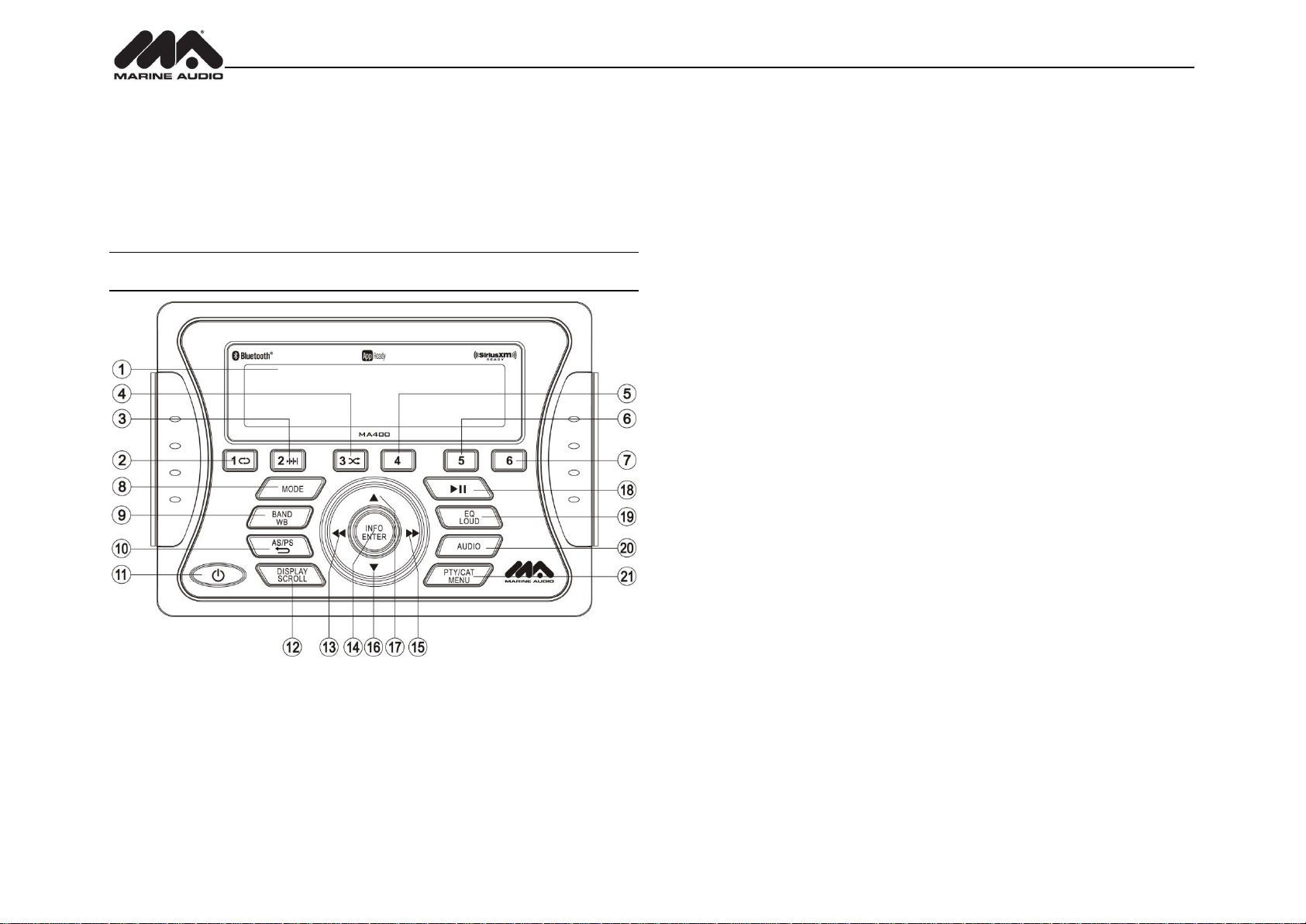
In SIRIUSXM mode, press the BAND/WB button (9) to access the SIRIUSXM user-preset
channel groups in the following order: SXM1, SXM2, SXM3.
Category Tuning
1. Press the PTY/CAT/MENU button (21) to access Category mode.
2. While in category mode, press ►►OR◄◄ buttons (15, 13) to choose a category.
3. Press ▲/▼buttons (17, 16) to choose desired channels in that category. (The current
channel number within the chosen category will always be the first channel tuned.)
4. Press the INFO/ENTER button (14) to play the highlighted channel and return to channel
tuning mode.
Channel Up/Down Tuning
Press the ►►/◄◄ buttons (13, 15) to search for a channel. Press and hold the
SEEK buttons to fast search.
Direct Tuning Mode
1. Press and hold the INFO/ENTER button (14) to enter direct tuning mode.
2. Press ▲/▼ buttons (17, 16) to change the first of three digits for the desired channel in
the direct entry screen.
3. Press the INFO/ENTER button to confirm the entered digit and move to the second digit
field.
4. Press ▲/▼ buttons to select the second digit.
5. Press the INFO/ENTER button to confirm the entered digit and move to the third digit field.
6. Press ▲/▼ buttons to select the third digit.
7. Press the INFO/ENTER button to confirm the three digit channel and tune to the selected
channel.
Accessing SIRIUSXM Mode
(Requires optional SIRIUSXM tuner)
Press the MODE button (8) as many times as necessary to change the mode to SIRIUSXM
radio mode.
Accessing your SIRIUSXM Radio ID
The SiriusXM ID is required for activation. To display your SIRIUSXM radio ID, use the ◄◄
button (13) to tune to channel “000”.The screen will display “SIRIUSXM ID” with the ID displayed
in the middle of the screen. The SIRIUSXM radio ID is 8 characters long and does not include
the letters I, O, S, or F.
Storing Preset Channels
The preset buttons (1-6) can be used to store 6 channels, allowing convenient access to your
favorite channels.
Programming Channels
1. Select the channel you want to store in memory.
2. Press and hold a 1-6 preset button until the corresponding preset button number appears.
3. Repeat steps 1 and 2 to program additional channels.
Preset Recall
Press one of the six preset buttons to directly select a preset channel stored in the current band.
Preset Scan
Press AS/PS button (10) to scan stations stored in all three user-preset channel groups (SXM1,
SXM2 and SXM3). The unit will pause for 10 seconds at each preset station. Press AS/PS again
12
Page 14
MA400
Signal Strength
Strength Display
No Signal
Weak
Good
Excellent
to stop scanning when the desired station is reached.
Preset Tuning
In Preset Tuning Mode, you can use the ►►OR◄◄ buttons (13, 15) to access all 18 preset
stations in sequential order.
Alternate Display Mode
Press the DISP/SCROLL button (12) to change the display information between single and dual
line text display. In dual line mode, both artist and title are available for viewing.
Press and hold the DISP/SCROLL button to scroll the Artist/Song Title information.
While in category tuning list mode, press the DISP/SCROLL button in sequence to change the
display information from Channel Name, Artist, and Song Title.
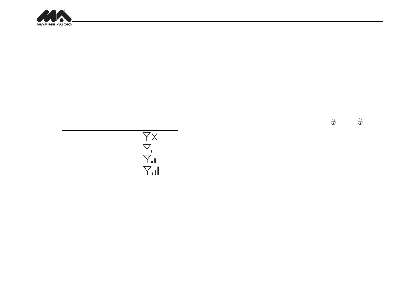
Satellite Signal Strength
The display will indicate satellite reception strength as shown below.
Channel Lock
Access Channel Lock through the System Menu under the “SiriusXM Satellite Radio” menu. See
“System Menu” on page 8. Select “Set Lock Code”.
1. Enter the default lock code of “0000”. To set the lock code:
a. Press the ▲/▼buttons (17, 16) to enter the first digit of the default code.
b. Press the INFO/ENTER button (14) to move to the next digit.
c. Repeat above steps to enter all 4 digits of the default code.
d. Press the ▲/▼buttons to enter the first digit of the new code.
e. Press the INFO/ENTER button to move to the next digit.
f. Repeat above steps to enter all 4 digits.
g. Repeat above steps to confirm the new code.
2. After setting a new four digit code, you can lock channels by entering the “Locked
Channels” menu.
3. Upon entering the code, you can navigate the list using the VOL +/- buttons to highlight
the channels.
4. Press the INFO/ENTER button (14) to Lock indicated by a ( ) or Unlock ( ) the
selected channel.
Reset SiriusXM Channel Lock Code
If you forget your Parental Control lock code, use the following directions to reset the code to the
default “0000”. Resetting the lock code will not affect the locked channels list.
1. In SiriusXM mode, tune to Channel 0
2. Set volume level to 0.
3. Press Power button (11) to power off the unit.
4. With power off, press and hold the Power button until the system version info is displayed
on the screen
5. Press and hold the Info/Enter button (14) until display turns off.
6. The lock code has now been reset to “0000”
13
Page 15
MA400
On-Screen Display
Advisory Message
Cause
Explanation/Solution
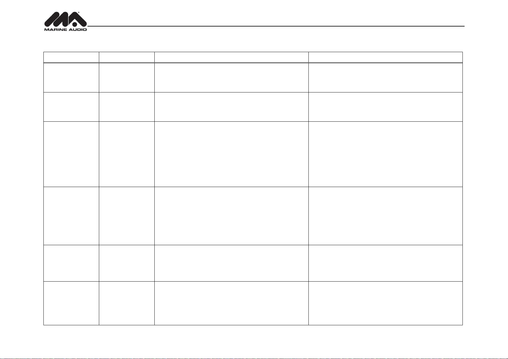
Check Antenna
Check Antenna
The radio has detected a fault with the SiriusXM antenna. The
antenna cable is either disconnected or damaged.
Verify that the antenna cable is connected to the SiriusXM
Connect Vehicle Tuner.
Inspect the antenna cable for damage and kinks. Replace the
antenna if the cable is damaged.
Check Tuner
Check Tuner
• The radio is having difficulty communicating with the SiriusXM
Connect Vehicle Tuner.
• The tuner may be disconnected or damaged.
Verify that the SiriusXM Connect Vehicle Tuner cable is securely
connected to the radio SiriusXM mating connector/ cable.
If the problem persists, disconnect and reconnect the tuner and
then contact your dealer.
No signal
No signal
The SiriusXM Connect Vehicle Tuner is having difficulty receiving the
SiriusXM satellite signal.
Verify that your vehicle is outdoors with a clear view of the
southern sky.
Verify that the SiriusXM magnetic mount antenna is mounted on a
metal surface on the outside the vehicle.
Move the SiriusXM antenna away from any obstructions.
Inspect the antenna cable for damage and kinks. Replace the
antenna if the cable is damaged.
If the problem persists, disconnect and reconnect the tuner and
then contact your dealer.
Scrolling “Subscription
Updated” – press any
key to continue”
Subscription Updated
The radio has detected a change in your SiriusXM subscription
status.
Press any key to clear the message.
No further action is required.
Questions about your subscription in the United States please
visit www.siriusxm.com/activatenow or call SiriusXM Listener
Care at 1-866-635-2349
Questions about your subscription in Canada, please visit
www.siriusxm.ca/activatexm or call XM Listener Care at
1-877-438-9677
Chan Unavailable
Channel Not Available
The channel that you have requested is not a valid SiriusXM channel
or the channel that you were listening to is no longer available. You
may also see this message briefly when first connecting a new
SiriusXM Connect Vehicle tuner. Visit www.siriusxm.com for more
information about the SiriusXM channel lineup.
Visit www.siriusxm.com/channellineupfor more information about the
SiriusXM channel lineup.
Ch Unsubscribed
Channel Not
Subscribed
The channel that you have requested is not included in your SiriusXM
subscription package or the channel that you were listening to is no
longer included in your SiriusXM subscription package.
Questions about your subscription in the United States please
visit www.siriusxm.com/activatenow or call SiriusXM Listener
Care at 1-866-635-2349.
Questions about your subscription in Canada please visit
www.siriusxm.ca/activatexm or call XM Listener Care at
1-877-438-9677.
Advisory Messages Reported by the SiriusXM Vehicle Tuner
14
Page 16
MA400
On-Screen Display
Advisory Message
Cause
Explanation/Solution
Channel Locked
Channel Locked
The channel that you have requested is Locked by the radio
Parental Control feature.
See the section on Parental Control, page 13 for more information on
the Parental Control feature and how to access locked channels.
“Enter Code?”
followed by ****
Enter Lock Code
User prompted to enter the lock/unlock code.
Enter the four digit code to play the audio.
Wrong Code
Invalid Lock Code
The unlock code entered by the user is incorrect
Input the correct four digit code to unlock the channel.
Reset lock code to default following instructions on page 13.
15
Page 17
MA400
iPod® OPERATION
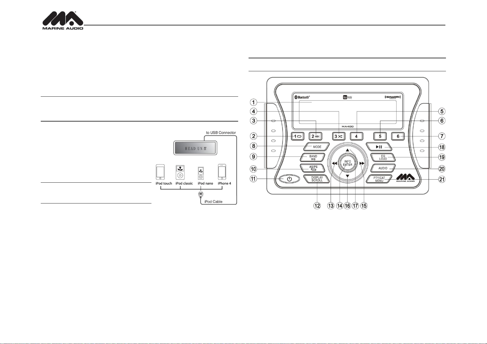
This unit is equipped with an iPod® ready function that will allow you to control your iPod (if
compatible) using the control panel buttons. The following models are supported:
iPod Nano 5G, 6G, 7G
iPod Classic
iPod Touch 3G, 4G, 5G
iPhone 4, 4S, 5, 5C, 5S
NOTE: Earlier model iPod’s are not supported because they do not implement the
required control protocol. Also, the iPod shuffle is not supported because it does not
utilize the 30-pin Apple iPod Connector. These unsupported iPod models may be
connected to the radio using one of the Auxiliary Inputs.
Accessing iPod Mode
The unit will automatically switch to iPod mode when
an iPod is plugged into the iPod cable. To return to
the iPod menu from any other source, press the
MODE button (8) on the control panel or remote
control until “iPod” appears on the display.
NOTE: The iPod will continuously recharge when
connected to the unit, as long as the vehicle
ignition is turned on.
Controlling Playback
Pausing Playback
During playback, press the ►║button (18) to pause playback. “Pause” will appear on the LCD.
Press ►║button again to resume playback.
Repeat Play
During playback, press the 1 button (2) to repeat the current song. “Repeat” will appear on the
LCD. Press 1 again to stop repeat playback.
Random Play
During playback, press the 3 button (4) to play all songs in the current category in random order.
Random play will begin once the current song has finished playing. “Shuffle” will appear on the
LCD. Press 3 again to stop random playback.
Selecting Tracks
During playback, press the ►►/◄◄ buttons (13, 15) to play the previous or next track in the
current category. Press the ►►/◄◄ button (13) once to play the song from the start position or
press SEEK |<< button twice to play the previous track.
Press and hold the ►►/◄◄ buttons (13, 15) to fast reverse/forward the song.
NOTE: If you press and hold the SEEK |<< or >>| button to change the current song to the
previous/next song, you will exit fast reverse/forward mode.
Alternate Display Mode
Press the DISPLAY/SCROLL button (12) to change the display information between single and
dual line text display. In dual line mode, both artist and title are available for viewing.
Playlist Search
Press the PTY/CAT/MENU button (21) to access Playlist selection mode. While in Category
mode, press the ▲/▼buttons (17, 16) to choose file search by Playlist, Artist, Album, Genre,
Song, Audiobook or Podcast. Press the INFO/ENTER button (14) to select the search mode.
Use the ▲/▼buttons (17, 16) buttons to search the available files on the iPod. Press the
INFO/ENTER button to play the selected song or file.
.
16
Page 18
MA400
Device 1
Device 5
BT Device
Press Enter
Device 1
Device 5
Lock/Unlock
Delete
Lock/Unlock
Delete
Press Enter
Use
BLUETOOTH OPERATION
The MA400 includes built-in Bluetooth technology that allows you to connect this head unit to
Bluetooth-enabled devices for streaming audio playback.
About Bluetooth Technology
Bluetooth wireless technology is a short-range wireless radio protocol. Operating in
the 2.4 GHz range, it transmits voice and data at speeds up to 2.1 Mbit/s over a range
of up to 10 meters.
Bluetooth Menu Options
NOTE: Please note that some Bluetooth menu options are only available while the unit is
in Bluetooth Audio mode.
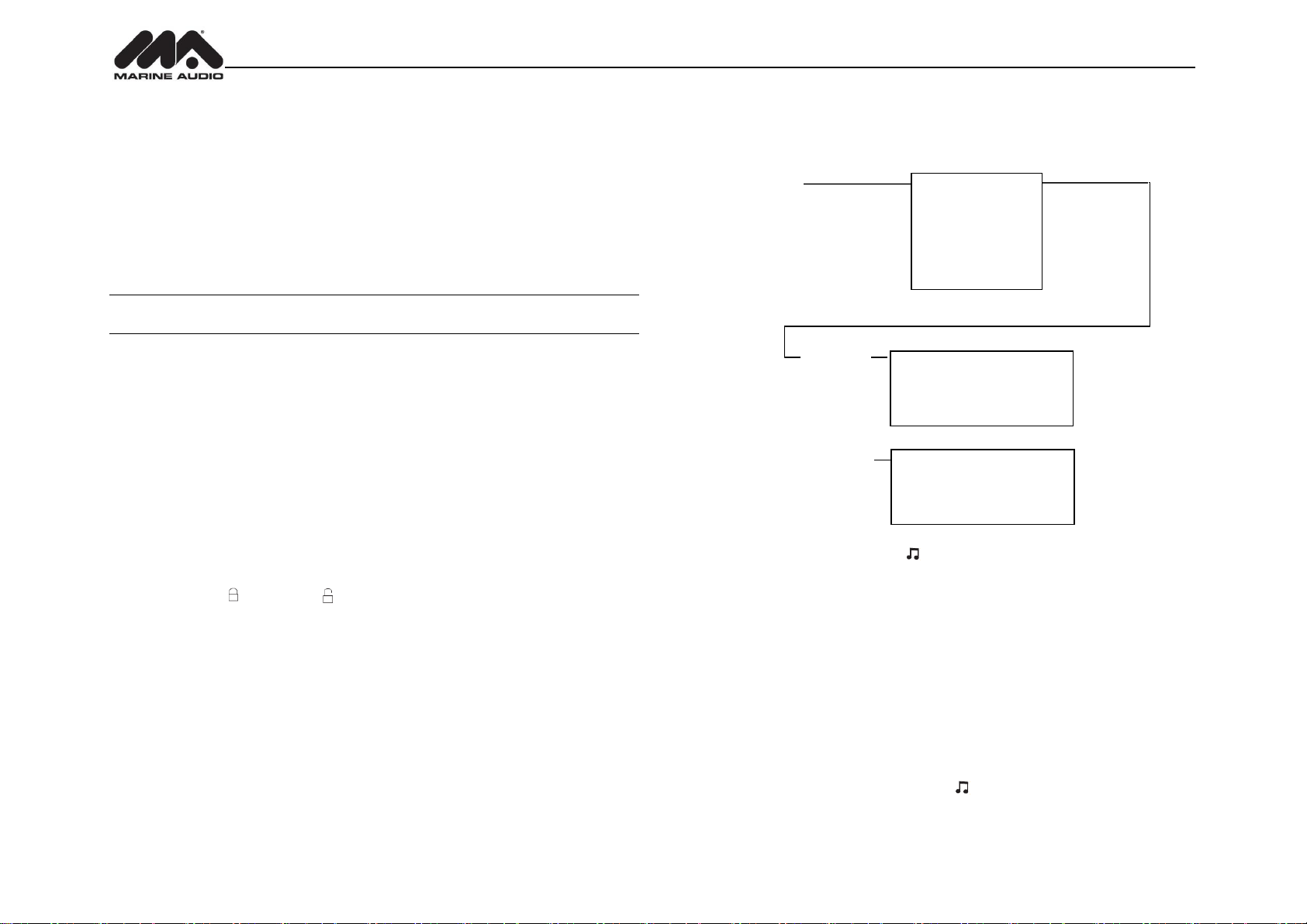
Press and hold the PTY/CAT/MENU button (21) to enter menu adjustment mode. Repeatedly
press the ▲/▼buttons (17, 16) to access the following Bluetooth Menu options:
BT ON/OFF: Press the ▲/▼buttons to choose “BT ON” or “BT OFF”, then press the
ENTER button (14) to select.
BT PAIR: Press the ▲/▼buttons to choose “ON” or “OFF”, then press the ENTER button
to start pairing mode.
BT DEVICE: Press the ENTER button to view a list of previously paired mobile devices.
Press the ▲/▼ buttons to view devices from the list. You cannot delete a device that is
actively connected. Press the ENTER button to select the device. Press the ▲/▼button
to choose Lock/Unlock, Disconnect or Delete for this device.
LOCK/UNLOCK: The MA400 can store up to 5 devices for Bluetooth connection.
The devices are stored in FIFO (First In First Out) order. To prevent a device from
being bumped from the list when more than 5 devices are used, you must lock the
device. To Lock/Unlock a device, press the ENTER button to display/change the
Locked ( ) or Unlocked ( ) icon.
DISCONNECT: To disconnect a paired device, press the ENTER button to
temporarily remove the Bluetooth link. The link can be re-established through your
phone menu by selecting the MA400 for connection.
DELETE: To delete a device from the list, press the ENTER button.
Pairing a Bluetooth Device
Before you begin, consult the owner’s manual for the Bluetooth device you want to pair with the
MA400.
1. Make sure the device is on and ready to receive a signal from the MA400. With the MA400
in Bluetooth Audio mode, choose BT Pair from the MA400 menu and press the ▲ button
to select ON. The unit is waiting to connect to a mobile phone device. With the BT function
of the mobile device turned on, search for a Bluetooth device.
2. When the Bluetooth device has completed its search, the mobile phone will display the
Bluetooth device name (MA400).
▼/▲
to Navigate
the List
Device 2
Device 3
Device 4
…
Connect/Disconnect
…
…
Connect/Disconnect
3. Select MA400. The BT AUDIO icon ( ) on the radio LCD will display.
4. Enter the pairing password (0000), if requested.
After connecting successfully, you will be able to listen to music stored on your Bluetooth
enabled device through the radio.
Answering a Call
When answering a call using a connected phone, Bluetooth audio playback will pause. After
hanging up from the call, Bluetooth audio playback will resume on most devices. It may be
necessary to press the play button on your device to resume playback.
BT Audio (A2DP)
The A2DP music is available for Bluetooth enabled phones when the phone is connected. To
access Bluetooth mode and play songs stored on your phone, press the MODE button (8).
While in Bluetooth mode, the Bluetooth Audio icon ( ) will be illuminated on the LCD.
17
Page 19

MA400
Selecting Tracks
During playback, press the ►►/◄◄button (13, 15) to play the previous or next track.
Pausing Playback
During playback, press the ►║button (18) to pause the Bluetooth audio playback. “A2DP ||” will
appear on the lower left corner LCD. Press ►║button again to resume playback.
If you change to another mode, the mobile device audio will pause. Press the MODE button (8)
to return to Bluetooth mode and resume mobile phone audio playback.
NOTE: If a Bluetooth device is disconnected due to the power being turned off or if the
device is out of range, the unit will automatically search for the matching Bluetooth
mobile device when the power is restored.
APP OPERATION
MARINE AUDIO® Specialty Controller is the ultimate wireless remote control for your MARINE
AUDIO stereo system. Store away your old remotes and enjoy the convenience of all the
primary functions of your MARINE AUDIO stereo right from your phone or tablet by transforming
your mobile device into a functional stereo remote control!
Features
This app controls all of the primary functions of your stereo features including:
Power on/off
Volume and mute
AM/FM radio tuner: access station, recall, store presets, switch songs
Bluetooth® streaming audio
File structure visibility, track selection, track audible scan up and down via USB
iPod/iPhone/iPad® control capabilities via USB
Auxiliary audio input control –auxiliary analog 1
Audio menu controls- bass, treble, balance, fader, equalizer and volume
Visual display feedback so you can see artist title and album on your mobile screen
Connecting and using MARINE AUDIO app
After downloading and installing MARINE AUDIO app on your apple device, pair your device to
the MA400 as stated above for Bluetooth paring. Once your device is paired you can open the
app and use as instructed with the MARINE AUDIO app manual found at
http://asaelectronics.com/manuals-guides.
When MARINE AUDIO is installed on Android operating system, close the app before Bluetooth
pairing, otherwise there may be errors on Bluetooth connection.
18
Page 20
MA400
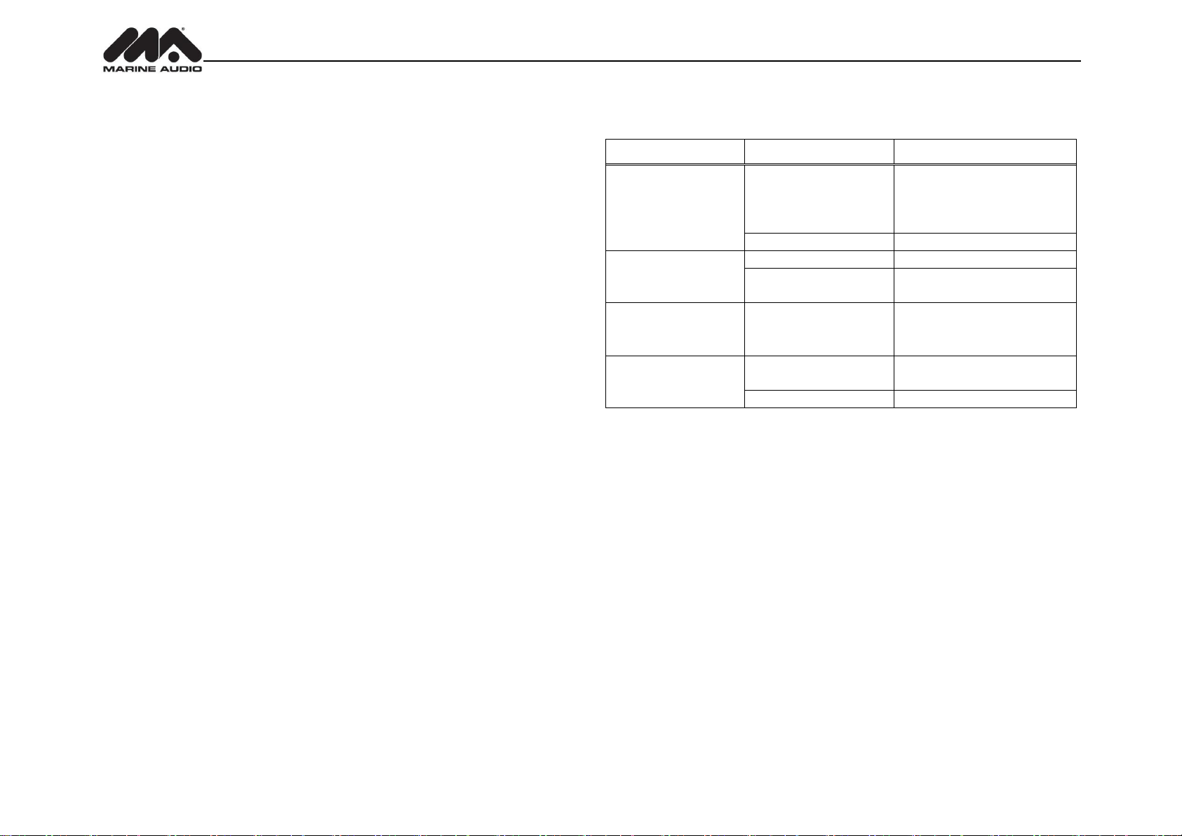
Symptom
Cause
Solution
No power
The vessel’s accessory
switch is not on
If the power supply is properly
connected to the vessel’s
accessory terminal, switch the
ignition key to “ACC”
Fuse is blown
Replace the fuse
No sound
Volume too low
Adjust volume to audible level
Wiring is not properly
connected
Check wiring connections
The operation keys do
not work
The built-in microcomputer
is not operating properly
due to noise
Press the RESET button
Cannot tune to radio
station, auto-seek does
not work
The antenna cable is not
connected
Insert the antenna cable firmly
Signals are too weak.
Select a station manually
CARE AND MAINTENANCE
Keep the product dry. If it does get wet, wipe it dry immediately. Liquids might contain
minerals that can corrode the electronic circuits.
Keep the product away from dust and dirt, which can cause premature wear of parts.
Handle the product gently and carefully. Dropping it can damage circuit boards and cases,
and can cause the product to work improperly.
Wipe the product with a dampened cloth occasionally to keep it looking new. Do not use
harsh chemicals, cleaning solvents, or strong detergents to clean the product.
Use and store the product only in normal temperature environments. High temperature
can shorten the life of electronic devices, damage batteries, and distort or melt plastic
parts.
Ignition
The most common source of noise in reception is the ignition system. This is a result of the radio
being placed close to the ignition system (engine). This type of noise can be easily detected
because it will vary in intensity of pitch with the speed of the engine.
Usually, the ignition noise can be suppressed considerably by using a radio suppression type
high voltage ignition wire and suppressor resistor in the ignition system. (Most vessels employ
this wire and resistor but it may be necessary to check them for correct operation.) Another
method of suppression is the use of additional noise suppressors. These can be obtained from
most CB/A radio or electronic supply shops.
Interference
Radio reception in a moving environment is very different from reception in a stationary
environment (home). It is very important to understand the difference.
AM reception will deteriorate when passing under a bridge or when passing under high voltage
lines. Although AM is subject to environmental noise, it has the ability to receive at great
distance. This is because broadcasting signals follow the curvature of the earth and are
reflected back by the upper atmosphere.
TROUBLESHOOTING
19
Page 21

MA400
SPECIFICATIONS
FM Radio
Frequency Coverage (USA) . . . . . . . . . . . . . . . . . . . . . . . . . . . . . . . . . . . . . . . . . 87.5 to 107.9 MHz
Frequency Coverage (Europe) . . . . . . . . . . . . . . . . . . . . . . . . . . . . . . . . . . . . . . . 87.5 to 108 MHz
Sensitivity (S/N=30dB) . . . . . . . . . . . . . . . . . . . . . . . . . . . . . . . . . . . . . . . . . . . . . . . . . . . . . . . 4 μV
Image Rejection . . . . . . . . . . . . . . . . . . . . . . . . . . . . . . . . . . . . . . . . . . . . . . . . . . . . . . . . . . .>45 dB
Stereo Separation . . . . . . . . . . . . . . . . . . . . . . . . . . . . . . . . . . . . . . . . . . . . . . . . . . . . . . . . . >25 dB
AM/MW
Frequency Range (USA). . . . . . . . . . . . . . . . . . . . . . . . . . . . . . . . . . . . . . . . . . . . . . . 530-1710 kHz
Frequency Range (Europe). . . . . . . . . . . . . . . . . . . . . . . . . . . . . . . . . . . . . . . . . . . . . 522-1620 kHz
Sensitivity (S/N=20dB) . . . . . . . . . . . . . . . . . . . . . . . . . . . . . . . . . . . . . . . . . . . . . . . . . . . . . 36 dB
General
Operating Voltage . . . . . . . . . . . . . . . . . . . . . . . . . . . . . . . . . . . . . . . . . . . . . . . .. . . . . . .DC 12 Volts
Grounding System . . . . . . . . . . . . . . . . . . . . . . . . . . . . . . . . . . . . . . . . . . . . . . . . . Negative Ground
Speaker Impedance . . . . . . . . . . . . . . . . . . . . . . . . . . . . . . . . . . . . . . . . . .4-8 Ω ohms per channel
Tone Controls:
Bass (at 100 Hz) . . . . . . . . . . . . . . . . . . . . . . . . . . . . . . . . . . . . . . . . . . . . . . . . . . . . . . . . ±10 dB
Treble (at 10 kHz) . . . . . . . . . . . . . . . . . . . . . . . . . . . . . . . . . . . . . . . . . . . . . . . . . . . . . . .±10 dB
Power Output . . . . . . . . . . . . . . . . . . . . . . . . . . . . . . . . . . . . . . . . . . . . . . . . . . . . . . . . . . 50W x 4
Current Drain . . . . . . . . . . . . . . . . . . . . . . . . . . . . . . . . . . . . . . . . . . . . . . . . . . . . . 15 Ampere (max.)
Commander Dimensions . . . . . . . . . . . . . . . . . . . . . . . . . . . . . . . . . . 5.15” (W) x 1.2” (D) x 3.7” (H)
Tuner/Amp Dimensions . . . . . . . . . . . . . . . . . . . . . . . . . . . . . . . . . . 8.35” (W) x 6.55” (D) x 2.4” (H)
.
FCC Notes
WARNING! Changes or modifications to this unit not expressly approved by the party
responsible for compliance could void the user’s authority to operate the equipment.
NOTE: This equipment has been tested and found to comply with the limits for a Class B
digital device, pursuant to Part 15 of the FCC Rules. These limits are designed to
provide reasonable protection against harmful interference in a residential installation.
This equipment generates, uses and can radiate radio frequency energy and, if not installed
and used in accordance with the instructions, may cause harmful interference to radio
communications.
However, there is no guarantee that interference will not occur in a particular installation. If this
equipment does cause harmful interference to radio or television reception, which can be
determined by turning the equipment off and on, the user is encouraged to try to correct the
interference by one or more of the following measures:
Reorient or relocate the receiving antenna.
Increase the separation between the equipment and receiver.
Connect the equipment into an outlet on a circuit different from that to which the receiver is
connected.
Consult the dealer or an experienced radio/TV technician for help.
20
Page 22

www.asaelectronics.com
v.190615
 Loading...