

SoundGraph Hummin’ 3.03 Quick Manual

-1-
Quick Guide
Version: 1.11.0224
SoundGraph, Inc.
-2-
List of Contents
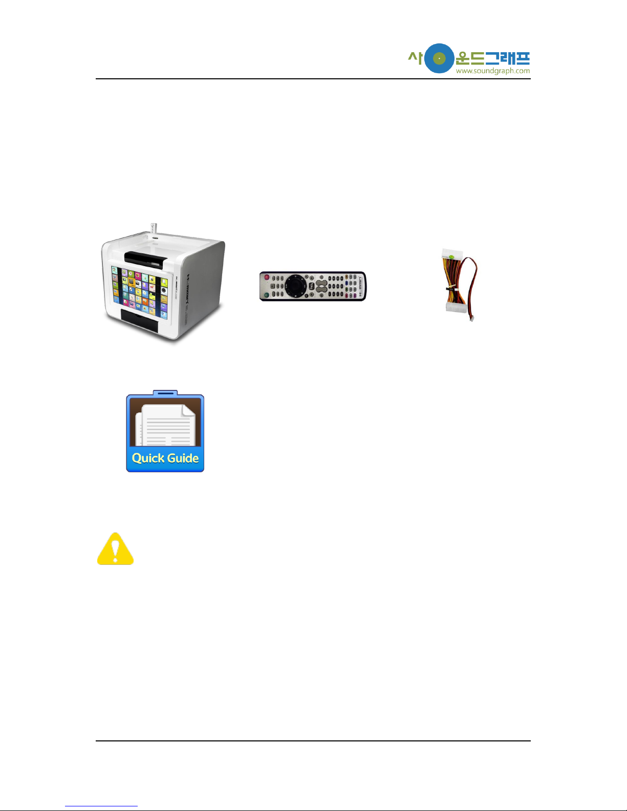
Thank you for purchasing Hummin’ 3.03 Enclosure. Please check the contents in this package
listed below.
Hummin’ 3.03 Enclosure
iMON Pad Remote Control
24/5 power cable
Quick Guide
Hummin’ 3.03 Enclosure
iMON Pad Remote Control
24/5 power cable
Quick Guide
In case of a barebone kit including Hummin’ 3.03 Enclosure, FingerVU 1016S/1016W
(Wired/Wireless) Monitor, FingerVU WUD (Wireless USB) Dongle and FingerVU 1016D
(Docking Station) may be included, or a set of mainboard, power supply and HDD
removable bay may be assembled in the enclosure.
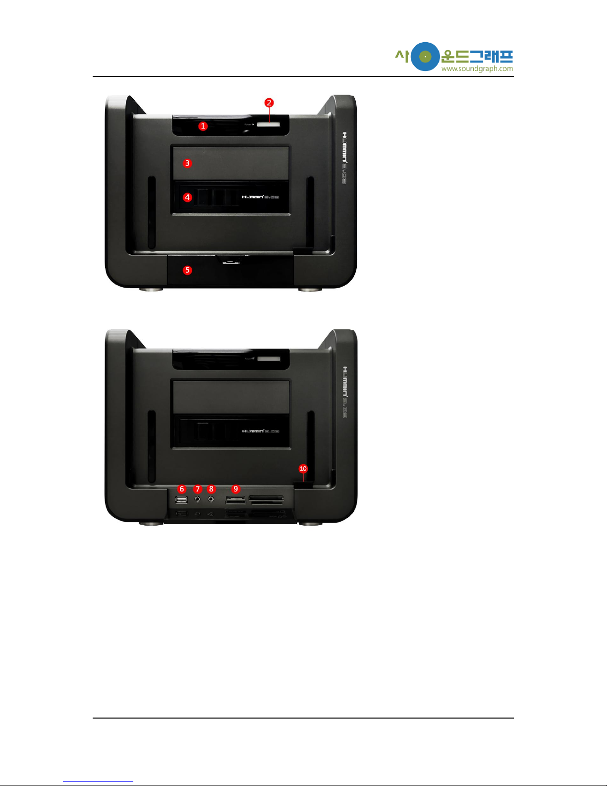
Nomenclature
Components of Hummin’ 3.03 Enclosure are listed with simple descriptions.
-3-
① Infrared (IR) receiver
② Power button
③ 5.25” Disk Driver bay (upper)
④ Removable Hard Disk Drive bay (lower)
⑤ Front I/O panel
⑥ Front USB port
⑦ Mic. input
⑧ Headphone output
⑨ Card reader
⑩ Front FingerVU 1016S/1016W docking connector
-4-
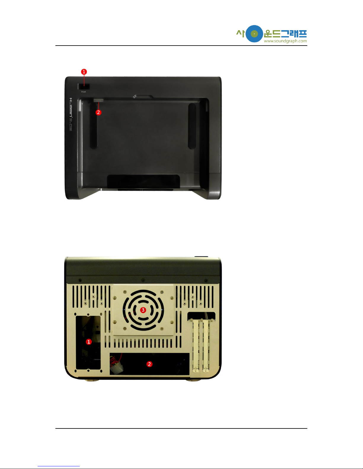
① FingerVU WUD connector
② Top FingerVU 1016S/1016W docking connector
① Mounting position for microATX power supply
② Mounting position for bracket on mainboard
③ Fan cover

-5-
Software Installation
Hummin’ 3.03 Enclosure can be used with iMON Manager Touch Frame, and HD Frame. These
applications are provided with FingerVU 1016S/1016W (Wired/Wireless) Monitor. Please refer to
the installation CD in FingerVU 1016S/1016W package you purchased.
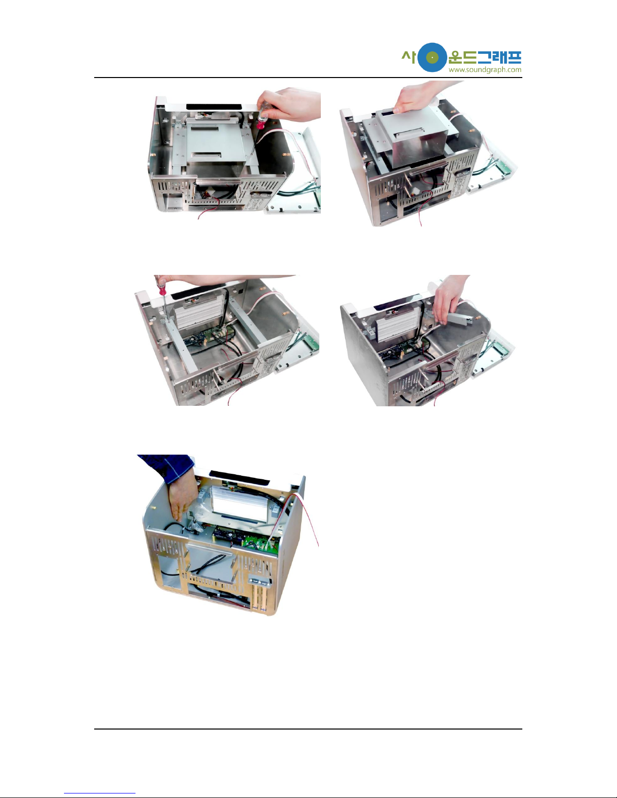
Hardware Installation
This section provides detailed installation procedure of Hummin’ 3.03 Enclosure. Please follow the
description of each step carefully.
1. Remove top cover
Remove the top cover of the enclosure by releasing 3 screws and pulling the cover
backward.
2. Remove fan cover on backside
Remove the fan cover on backside of the enclosure by releasing 4 screws. This is
necessary step for connection of Optical Disk Drive cables in further steps.
3. Remove 5.25” disk drive bay
-6-
Remove the 5.25” disk drive bay from the drive bay support by releasing 4 screws.
4. Remove drive bay support
Remove the drive bay support from the enclosure by releasing 4 screws (B type).
5. Remove screw set for assembly
Remove the screw set for assembly placed on backside of the front panel.
6. Mount Bracket on Mainboard
 Loading...