

Page 1

PF150C13
Designed for 2013 and newer Ford® F-150 Super-Crew vehicles
Subwoofer Assembly
Subwoofer Power Harness
Subwoofer Body
Harness
M6 Bolts x3
M6 Nut Inserts x3
(Requires Nut Insert Tool)
Wire Taps
Adapter Harness
©2012 Stillwater Designs
PF150C13-A1-20121108
25A Fuse
Wire Ties x6
Foam Strips
1
Page 2
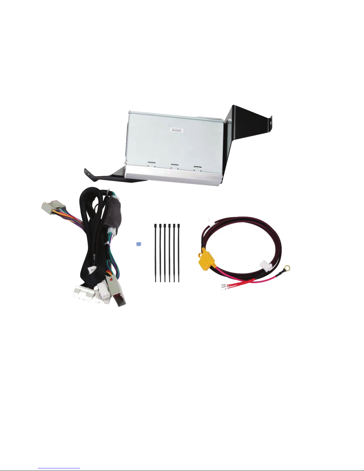
Amplifi er Body
Harness
Amplifi er Assembly
Amplifi er Power
Harness
2
25A Fuse
Wire Ties x6
Page 3
Radio Removal (Trucks with Console Mounted Shifter)
1. Set the parking brake.
2. Turn the ignition switch to the run position (do not start).
3. Shift the transmission to “Neutral”.
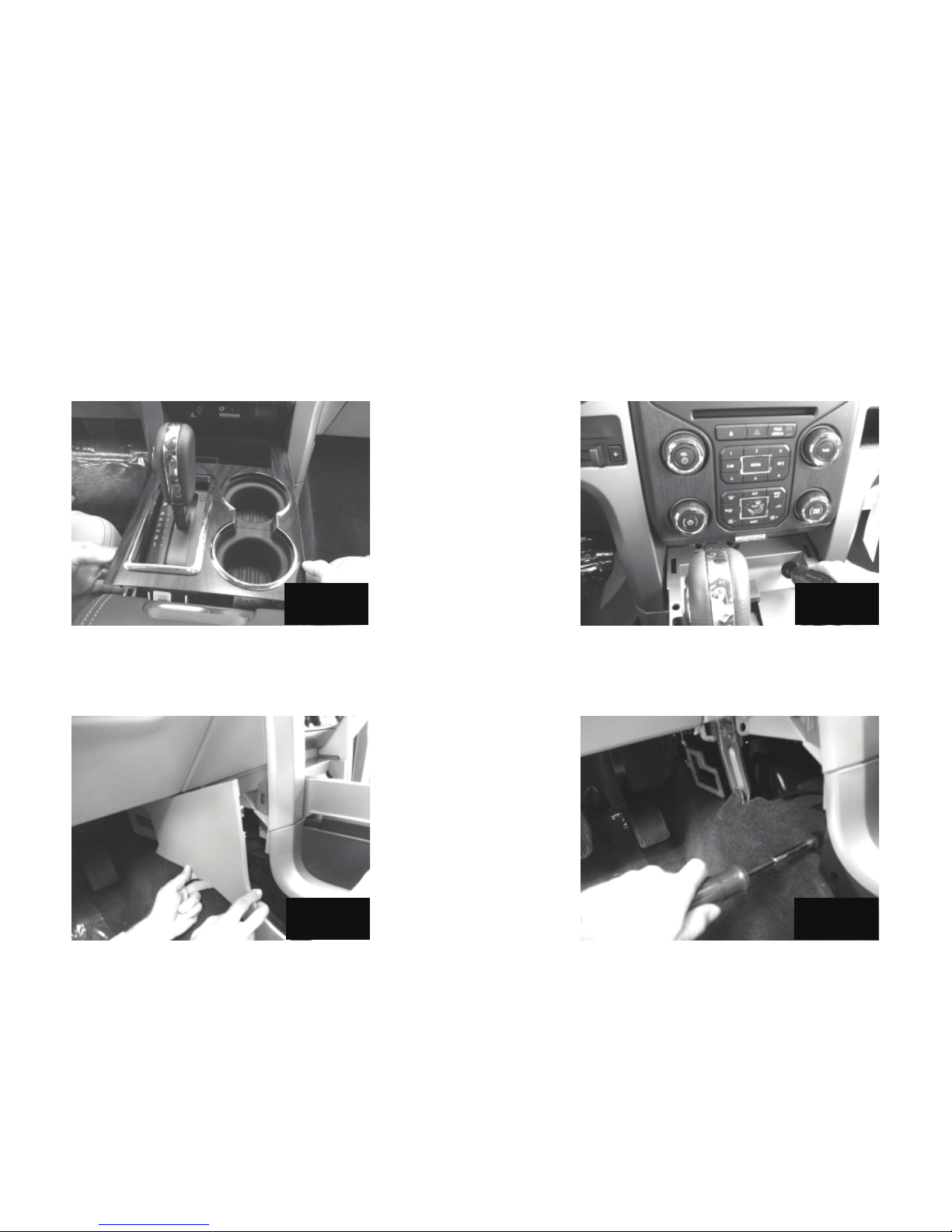
4. Lift up on the shifter bezel to remove. Disconnect wire if necessary. Fig. 1
5. Return transmission to park and turn ignition switch to off.
6. Open the hood, disconnect the negative battery cable
7. Remove the two screws on the top front of the console. Fig. 2
Fig. 1
8. Remove the side panel of the console by pulling loose. Fig. 3
9. Remove the screw on each side of the console toward the front. Fig. 4
Fig. 2
Fig. 3
10. Slide both front seats all the way forward. (For trucks with power sliding seats temporarily reconnect the
negative battery cable in order to move seats.)
Fig. 4
3
Page 4
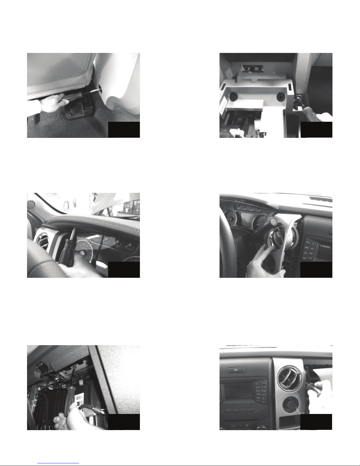
11. Remove screw on each side of the rear of the console. Fig. 5
12. Slide the console back approximately three inches to allow access to the screws securing the bottom of
the left and right vent assemblies and remove the screws. Fig. 6
Fig. 5
Fig. 6
13. Remove the two screws in the top of the instrument cluster bezel. Fig. 7
14. Pull the bezel loose, but do not completely remove. The bezel just needs to be loose enough to allow
the left vent assembly to be removed.
15. Pull loose the left vent assembly and remove. Fig. 8
Fig. 7
Fig. 8
16. Open the glove compartment and squeeze the sides inward to allow it to fold all the way down.
17. Find the three bolts securing the passenger side airbag assembly and remove them. Fig. 9
18. Pull the air bag assembly out approximately three inches to gain access to the screw securing the top of
the right vent assembly and remove the screw. Place a towel under the airbag assembly to prevent it from
scratching the dash. Fig. 10
Fig. 9
Fig. 10
4
Page 5
Do Not Disconnect Any Airbag Wiring.
19. Pull the left vent assembly loose and disconnect wiring.
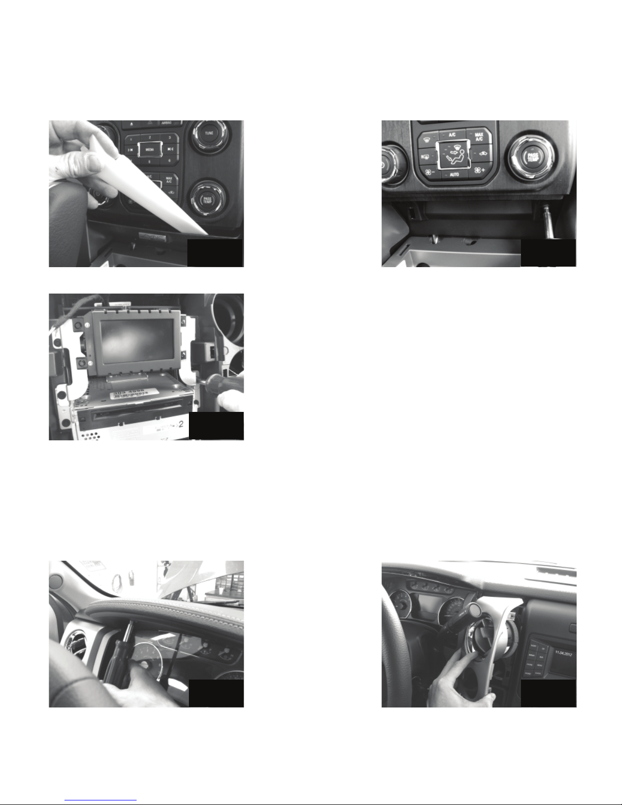
20. Pry loose the small trim panel below the HVAC controls. Fig. 11
21. Remove the two screws securing the bottom of the radio bezel. Fig. 12
Fig. 11
Fig. 12
22. Pull loose the radio bezel and disconnect wiring.
23. Remove the eight screws securing the display screen bracket and radio, remove radio and disconnect wiring. Fig. 13
Fig. 13
Radio Removal (Trucks with Column Mounted Shifter)
24. Remove the two screws in the top of the instrument cluster bezel. Fig. 14
25. Pull the bezel loose, but do not completely remove. The bezel just needs to be loose enough to allow
the left vent assembly to be removed.
26. Pull loose the left vent assembly and remove. Fig. 15
Fig. 14
Fig. 15
5
Page 6
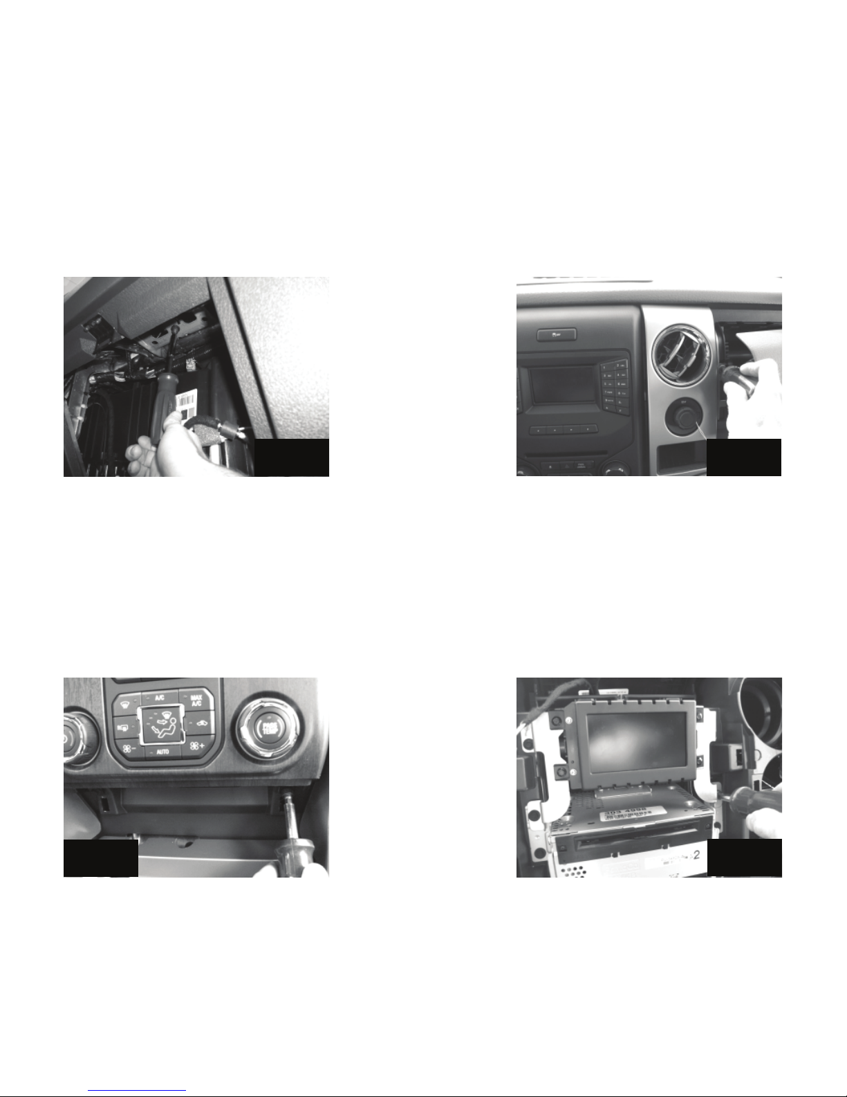
27. Open the glove compartment and squeeze the sides inward to allow it to fold all the way down.
28. Find the three bolts securing the passenger side airbag assembly and remove them. Fig. 16
29. Pull the air bag assembly out approximately three inches to gain access to the screw securing the top of
the right vent assembly and remove the screw. Place a towel under the airbag assembly to prevent it from
scratching the dash. Fig. 17
Fig. 16
Fig. 17
Do Not Disconnect Any Airbag Wiring.
30. Pull the left vent assembly loose and disconnect wiring.
31. Open the Aux Input Cover below the HVAC controls and remove the two screws securing the radio
bezel. Fig. 18
32. Pull loose the radio bezel and disconnect wiring.
33. Remove the eight screws securing the display screen bracket and radio, remove radio and disconnect
wiring. Fig. 19
Fig. 18
6
Fig. 19
Page 7

Power Wire Routing
34. Find the fuse box in the engine compartment and open the cover.
35. Remove the nut on the accessory lug, connect the power wires and retighten the nut. Torque to 9Nm.
Fig. 20
36. Route the amplifi er power wire, which has three metal terminals on the end, across the radiator support
and toward the grommet on the driver’s side of the fi rewall. Secure with supplied wire ties. Fig. 21
Secure
Harness
Here
Connect
Power Wire
Here
Fig. 20
Grommet
for amp
Fig. 21
37. Route the power wire for the subwoofer across the radiator support and toward the grommet on the
passenger’s side of the fi rewall. Secure with supplied wire ties. Fig. 22
38. Make a small incision in the both rubber grommets and pass the power wires into the cabin.
39. Remove the driver’s side threshold panel along the bottom of the front door opening.
40. Pull back the rubber door molding and then pull back on the kick panel to remove it. Fig. 23
Grommet
for
subwoofer
power wire
Fig. 22
Amplifi er Harness Routing
41. Route the amplifi er body harness from the radio opening down to the area in front of the brake pedal.
The white connectors connect to the amplifi er.
42. Connect the radio speaker/power connecter to the amplifi er harness.
43. Connect the other end of the amplifi er body harness to the back of the radio, reconnect the other radio
connections, then reinstall radio.
44. Connect amplifi er body harness to the amplifi er.
Fig. 23
7
Page 8
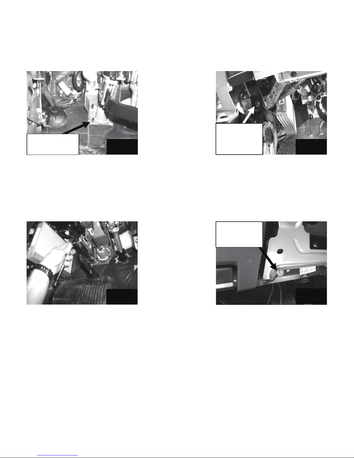
45. Remove the lower left nut securing the brake booster to the fi re wall. Fig. 24
46. Remove the screw securing the parking brake release handle.
47. Slide the amplifi er bracket over the brake booster stud and then line up the hole in the front of the bracket with the hole in the parking brake release then reinstall the parking brake release screw. Fig. 25
Remove nut
from this stud.
Fig. 24
Amplifier
mounted over
parking brake
Fig. 25
Place your warranty card in the glove box for future use.
48. Reinstall the brake booster nut and tighten. Torque to 25Nm. Fig. 26
49. Remove the three screws securing the plastic panel below the steering column and then snap loose.
50. IMPORTANT: Ground the black ground wire of the amplifi er harness to the lower left bolt securing the
metal knee bolster. Torque to 14Nm. Fig. 27
Connect black
ground wire
Fig. 26
51. Install the white three pin connector on the end of the amplifi er power harness inside the cabin. It does
not matter what order the three wires are in on the three pin connecter but the terminals can only be inserted
one way. If the terminal will not go into the connecter simply turn it 180 degrees and try again. Push the
terminals in until they click and lock into place. Install the black two pin connector on the end of the
subwoofer power harness inside the cabin. The black connector should have a block out plug installed in
one side to prevent the power wire from being inserted into the wrong position in the connector.
52. Connect the white three-pin connector of the amplifi er harness to the corresponding connector of the
amplifi er power harness.
53. Connect the black two-pin connecter to the power wire to the corresponding connector of the
subwoofer harness.
8
Fig. 27
Page 9
Subwoofer Installation
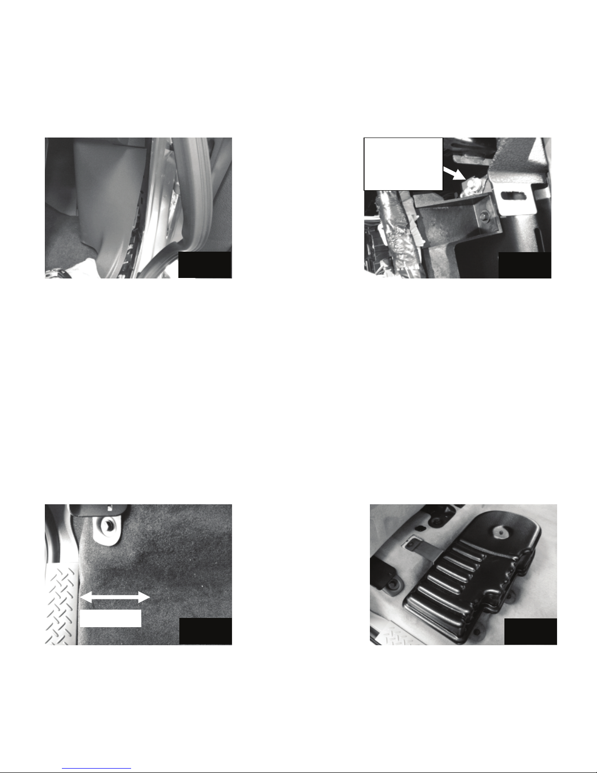
54. Remove the passenger’s side threshold panel along the bottom of the front and rear door openings.
55. Pull back the rubber door molding and then pull back on the kick panel to remove it. Fig. 28
56. IMPORTANT: Connect the black ground wire of the subwoofer harness to the factory ground point in the
passenger’s side kick panel. Torque to 9Nm. Fig. 29
Fig. 28
Connect black
ground wire of
subwoofer
Fig. 29
57. Route the subwoofer harness along the door opening and toward the rear of the cab.
58. Route the white two-pin connecter of the subwoofer harness to the two-pin connecter on the amplifi er
harness.
59. If the truck is equipped with the factory subwoofer option, run the subwoofer harness through the
incision that the factory subwoofer harness comes through. Tuck the factory wires under the carpet out of
the way.
60. If the truck was not equipped with the factory subwoofer option, measure fi ve inches from the sill plate
under the rear seat and make an incision in the carpet where the subwoofer enclosure will reside and pull
the subwoofer harness through the incision. Fig. 30
61. If the truck was equipped with the factory subwoofer, use the original bolts to secure the new subwoofer
enclosure to the fl oor.
62. If the truck was not equipped with the factory subwoofer option, fi nd the three mounting holes in the
sheet metal. Cut a small hole in the carpet above each hole and install the supplied nut inserts.
63. Secure the subwoofer with the supplied M6 bolts. Fig. 31
5 inches
Fig. 30
64. Install fuses into fuse holders.
65. Reinstall all previously remove parts in reverse order.
66. Reconnect negative battery cable. Torque to 7Nm.
Fig. 31
9
Page 10

Troubleshooting the Kicker Integrated Systems
If you experience a problem once the Subwoofer is installed, use this guide to locate the trouble.
The radio is working, but the Subwoofer is not working:
• Check the battery voltage to make sure it is not discharged below 11 volts.
• Check the negative battery cable to see if it has been securely tightened back on the battery.
• Check the inline fuse located near the battery to make sure it is plugged in completely, and not blown.
• Check the inline +12Volt power-connector near the fi rewall to make sure it is plugged in securely.
• Check the inline connectors near the subwoofer enclosure to make sure they are plugged securely.
• Check the ground wire connection to make sure it is tightly secured to the proper ground in the vehicle.
• Check the audio input signal connection to make sure it is secure and connected to the proper wiring.
• Test with different music in case there is no low frequency audio in the initial sound check.
There is a buzz or rattle noise that accompanies the low frequency element of the music:
• Check for a connector or any other object that could be very near the enclosure.
• Check the subwoofer enclosure mounting brackets to make sure they are secure.
There is a problem with the multi-channel stereo amplifi er:
• Check the battery voltage to make sure it is not discharged below 11 volts.
• Check the negative battery cable to see if it has been securely tightened back on the battery.
• Check the inline fuse located near the battery to see if it is plugged in completely and not blown.
• Check the multi-pin connecters at the back of the radio and at the amplifi er chassis to make sure they
are plugged all the way in.
• Check the ground wire connection to make sure it is tightly secured to the proper ground in the vehicle.
10
Page 11

Symptom Possible Cause Solution
No Subwoofer Output
Fuse not installed in inline fuse
holder on subwoofer and / or amp
harness
Install fuse into fuse holder.
Refer to instructions for correct
placement
Low battery voltage Recharge the battery
Negative battery cable not
Reconnect negative battery cable
connected
Power wire connector not
connected to body harness
Connect power wire to body
harness. Check for loose
connection
Ground wire not grounded properly Check ground wire with voltmeter
to insure it is a good ground
Balance or fader controls not set to
neutral position
Set balance and fader control to
center settings. (only effects stand
alone subwoofer kit)
No low frequency information in
Test with several different songs
music
Subwoofer harness not properly
/ completely connected to subwoofer.
Securely fasten both of the
connectors on the subwoofer
harness to the subwoofer. Check
for loose connections.
Blown radio fuse Refer to owner's manual for radio
Radio Not Coming On
fuse location and value
Low battery voltage Recharge the battery
Radio Comes On, But No
Sound From Any Speakers
Fuse not installed in inline fuse
holder on amplifi er harness
Ground wire not grounded properly Check ground wire with voltmeter
Install fuse into fuse holder. Refer
to instructions for correct place-
ment
to insure it is a good ground
Low battery voltage Recharge the battery
If you continue to experience problems after troubleshooting, please contact KICKER Technical Support at
(800) 256-0808 ext. 6009, or [email protected].
11
Page 12

stillwater designs
P.O. Box 459 • Stillwater, Oklahoma 74076 • USA • (405) 624–8510
12
 Loading...