

SoundFont® Technical Specification
®
Version 2.04
February 3, 2006
0 About This Document
0.1 Revision History
Rev. Date Description
2.04 September 10, 2002 Add support for 24 bit samples
2.01 August 2, 1997 Add specification for Modulators and standard NRPN implementation
2.00b May 2, 1997 Change nomenclature from layer/split to zone. See glossary
Fix a few typos
2.00a October 18, 1995 First publicly released draft
0.2 Disclaimers
THIS SPECIFICATION IS PROVIDED “AS IS” WITH NO WARRANTIES WHATSOEVER INCLUDING ANY
WARRANTY OF MERCHANTABILITY, FITNESS FOR ANY PARTICULAR PURPOSE, OR ANY WARRANTEE
OTHERWISE ARISING OUT OF ANY PROPOSAL, SPECIFICATION, OR SAMPLE.
A LICENSE IS HEREBY GRANTED TO COPY, REPRODUCE, AND DISTRIBUTE THIS SPECIFICATION FOR
INTERNAL USE ONLY. NO OTHER LICENSE EXPRESS OR IMPLIED, BY ESTOPPEL OR OTHERWISE, TO ANY
OTHER INTELLECTUAL PROPERTY RIGHTS IS GRANTED OR INTENDED HEREBY.
AUTHORS OF THIS SPECIFICATION DISCLAIM ALL LIABILITY, INCLUDING LIABILITY FOR
INFRINGEMENT OF PROPRIETARY RIGHTS, RELATING TO IMPLEMENTATION OF INFORMATION IN THIS
SPECIFICATION. AUTHORS OF THIS SPECIFICATION ALSO DO NOT WARRANT OR REPRESENT THAT
SUCH IMPLEMENTATION (S) WILL NOT INFRINGE ON SUCH RIGHTS.
This preliminary document is being distributed solely for the purpose of rev iew an d solicitation of comments. It will be
updated periodically. No products should rely on the content of this version of the document.
SoundFont® and the SoundFont logo is a registered trademark of E-mu Systems, Inc. E-mu Systems licenses a “SoundFont
Compatibility” logo for a nominal fee; please contact E-mu’s SoundFont administrator by FAX at (408) 439-0392 for more
information. Users of the information contained herein should refer to files conforming to the specification as “SoundFont
Compatible,” with appropriate acknowledgment of trademark ownership.
0.3 Updates and Comments
Please visit http://www.soundfont.com for specification updates, and please send comments via e-mail to
soundfont@emu.com.
SoundFont 2.01 Technical Specification - Page 1 - Printed 12/10/1996 5:57 PM

0.4 Table of Contents
0 ABOUT THIS DOCUMENT ..............................................................................................................................................1
0.1 REVISION HISTORY..........................................................................................................................................................1
0.2 DISCLAIMERS...................................................................................................................................................................1
0.3 UPDATES AND COMMENTS...............................................................................................................................................1
0.5 ILLUSTRATIONS ...............................................................................................................................................................4
1 INTRODUCTION................................................................................................................................................................5
1.1 SCOPE AND INTENDED PURPOSE OF THIS DOCUMENT.......................................................................................................5
1.2 DOCUMENT ORGANIZATION ............................................................................................................................................5
1.3 SOUNDFONT 2 OBJECTIVES .............................................................................................................................................5
1.4 SOUNDFONT 1.X ..............................................................................................................................................................5
1.5 FUTURE ENHANCEMENTS TO THE SOUNDFONT 2 STANDARD ..........................................................................................6
2 TERMS AND ABBREVIATIONS .....................................................................................................................................6
2.1 DATA STRUCTURE TERMINOLOGY...................................................................................................................................6
2.2 SYNTHESIZER TERMINOLOGY ..........................................................................................................................................7
2.3 PARAMETER TERMINOLOGY ..........................................................................................................................................10
3 RIFF STRUCTURE...........................................................................................................................................................11
3.1 GENERAL RIFF FILE STRUCTURE ..................................................................................................................................11
3.2 THE SOUNDFONT 2 CHUNKS AND SUB-CHUNKS ............................................................................................................12
3.3 REDUNDANCY AND ERROR HANDLING IN THE RIFF STRUCTURE...................................................................................12
4 SOUNDFONT 2 RIFF FILE FORMAT ..........................................................................................................................12
4.1 SOUNDFONT 2 RIFF FILE FORMAT LEVEL 0..................................................................................................................12
4.2 SOUNDFONT 2 RIFF FILE FORMAT LEVEL 1...................................................................................................................12
4.3 SOUNDFONT 2 RIFF FILE FORMAT LEVEL 2...................................................................................................................13
4.4 SOUNDFONT 2 RIFF FILE FORMAT LEVEL 3...................................................................................................................14
4.5 SOUNDFONT 2 RIFF FILE FORMAT TYPE DEFINITIONS ..................................................................................................15
5 THE INFO-LIST CHUNK................................................................................................................................................16
5.1 THE IFIL SUB-CHUNK .....................................................................................................................................................16
5.2 THE ISNG SUB-CHUNK....................................................................................................................................................17
5.3 THE INAM SUB-CHUNK ................................................................................................................................................17
5.4 THE IROM SUB-CHUNK...................................................................................................................................................17
5.5 THE IVER SUB-CHUNK....................................................................................................................................................17
5.6 THE ICRD SUB-CHUNK .................................................................................................................................................18
5.7 THE IENG SUB-CHUNK .................................................................................................................................................18
5.8 THE IPRD SUB-CHUNK..................................................................................................................................................19
5.9 THE ICOP SUB-CHUNK..................................................................................................................................................19
5.10 THE ICMT SUB-CHUNK...............................................................................................................................................19
5.11 THE ISFT SUB-CHUNK.................................................................................................................................................19
6 THE SDTA-LIST CHUNK ...............................................................................................................................................20
6.1 SAMPLE DATA FORMAT IN THE SMPL SUB-CHUNK.........................................................................................................20
6.2 SAMPLE DATA FORMAT IN THE SM24 SUB-CHUNK .........................................................................................................20
6.3 SAMPLE DATA LOOPING RULES.....................................................................................................................................20
7 THE PDTA-LIST CHUNK...............................................................................................................................................21
7.1 THE HYDRA DATA STRUCTURE...................................................................................................................................21
7.2 THE PHDR SUB-CHUNK ................................................................................................................................................21
7.3 THE PBAG SUB-CHUNK ................................................................................................................................................22
7.4 THE PMOD SUB-CHUNK ...............................................................................................................................................23
SoundFont 2.01 Technical Specification - Page 2 - Printed 12/10/1996 5:57 PM

THE PGEN SUB-CHUNK ................................................................................................................................................24
7.5
7.6 THE INST SUB-CHUNK..................................................................................................................................................25
7.7 THE IBAG SUB-CHUNK .................................................................................................................................................25
7.8 THE IMOD SUB-CHUNK ................................................................................................................................................26
7.9 THE IGEN SUB-CHUNK .................................................................................................................................................27
7.10 THE SHDR SUB-CHUNK ..............................................................................................................................................28
8 ENUMERATORS..............................................................................................................................................................29
8.1 GENERATOR AND MODULATOR DESTINATION ENUMERATORS......................................................................................29
8.1.1 Kinds of Generator Enumerators .........................................................................................................................30
8.1.2 Generator Enumerators Defined..........................................................................................................................30
8.1.3 Generator Summary .............................................................................................................................................37
8.2 MODULATOR SOURCE ENUMERATORS...........................................................................................................................38
8.2.1 Source Enumerator Controller Palettes................................................................................................................39
8.2.2 Source Directions ..................................................................................................................................................40
8.2.3 Source Polarities ...................................................................................................................................................40
8.2.4 Source Types..........................................................................................................................................................40
8.3 MODULATOR TRANSFORM ENUMERATORS....................................................................................................................41
8.4 DEFAULT MODULATORS................................................................................................................................................41
8.4.1 MIDI Note-On Velocity to Initial Attenuation......................................................................................................41
8.4.2 MIDI Note-On Velocity to Filter Cutoff................................................................................................................42
8.4.3 MIDI Channel Pressure to Vibrato LFO Pitch Depth..........................................................................................42
8.4.4 MIDI Continuous Controller 1 to Vibrato LFO Pitch Depth...............................................................................42
8.4.5 MIDI Continuous Controller 7 to Initial Attenuation...........................................................................................43
8.4.6 MIDI Continuous Controller 10 to Pan Position .................................................................................................43
8.4.7 MIDI Continuous Controller 11 to Initial Attenuation.........................................................................................43
8.4.8 MIDI Continuous Controller 91 to Reverb Effects Send......................................................................................44
8.4.9 MIDI Continuous Controller 93 to Chorus Effects Send......................................................................................44
8.4.10 MIDI Pitch Wheel to Initial Pitch Controlled by MIDI Pitch Wheel Sensitivity................................................44
8.5 PRECEDENCE AND ABSOLUTE AND RELATIVE VALUES...................................................................................................45
9 PARAMETERS AND SYNTHESIS MODEL .................................................................................................................45
9.1 SYNTHESIS MODEL........................................................................................................................................................46
9.1.1 Wavetable Oscillator............................................................................................................................................46
9.1.2 Sample Looping....................................................................................................................................................46
9.1.3 Low-pass Filter.....................................................................................................................................................46
9.1.4 Final Gain Amplifier.............................................................................................................................................47
9.1.5 Effects Sends.........................................................................................................................................................47
9.1.6 Low Frequency Oscillators...................................................................................................................................47
9.1.7 Envelope Generators............................................................................................................................................47
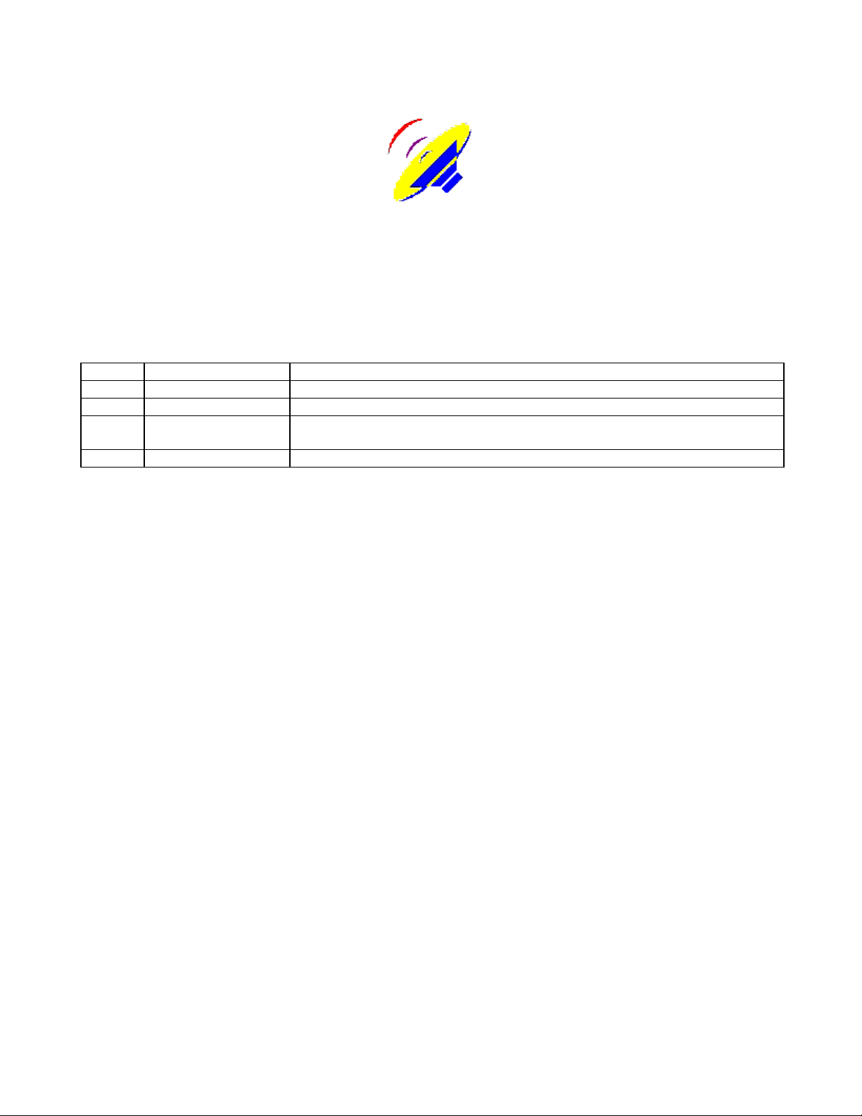
9.1.8 Modulation Interconnection Summary.................................................................................................................48
9.2 MIDI FUNCTIONS ..........................................................................................................................................................48
9.3 PARAMETER UNITS........................................................................................................................................................49
9.4 THE SOUNDFONT GENERATOR MODEL ..........................................................................................................................50
9.5 THE SOUNDFONT MODULATOR CONTROLLER MODEL...................................................................................................51
9.5.1 Controller Model Theory of Operation .................................................................................................................51
9.5.2 Pictorial Examples of Source Types......................................................................................................................55
9.5.3 Mappings of Modulator Sources to the SoundFont Controller Input Domain......................................................58
9.5.4 Linked Modulator Description ..............................................................................................................................58
9.6 SOUNDFONT 2.01 STANDARD NRPN IMPLEMENTATION ...............................................................................................59
9.6.1 The NRPN Message...............................................................................................................................................59
9.6.2 The NRPN Select Values........................................................................................................................................59
9.6.3 The Default Data Entry Ranges.............................................................................................................................60
9.7 ON IMPLEMENTATION ACCURACY..................................................................................................................................61
10 ERROR HANDLING ......................................................................................................................................................61
SoundFont 2.01 Technical Specification - Page 3 - Printed 12/10/1996 5:57 PM

STRUCTURAL ERRORS .................................................................................................................................................61
10.1
10.2 UNKNOWN CHUNKS.....................................................................................................................................................61
10.3 UNKNOWN ENUMERATORS..........................................................................................................................................62
10.4 ILLEGAL PARAMETER VALUES ....................................................................................................................................62
10.5 OUT-OF-RANGE VALUES..............................................................................................................................................62
10.6 MISSING REQUIRED PARAMETER OR TERMINATOR......................................................................................................62
10.7 ILLEGAL ENUMERATOR................................................................................................................................................62
11 SILICON SOUNDFONTS...............................................................................................................................................62
11.1 SILICON SOUNDFONT OVERVIEW ................................................................................................................................63
11.2 SILICON SOUNDFONT ROM HEADER FORMAT............................................................................................................63
12 GLOSSARY......................................................................................................................................................................64
0.5 Illustrations
F
IGURE 1: IDEAL FILTER RESPONSE ..........................................................................................................................................47
IGURE 2: GENERATOR BASED MODULATION STRUCTURE.......................................................................................................48
F
IGURE 3: SOUNDFONT MODULATOR BUILDING BLOCK...........................................................................................................52
F
IGURE 4: DETAILED SOUNDFONT MODULATOR BUILDING BLOCK..........................................................................................53
F
IGURE 5: POSITIVE UNIPOLAR LINEAR PLOT ...........................................................................................................................55
F
IGURE 6: POSITIVE BIPOLAR LINEAR PLOT..............................................................................................................................55
F
IGURE 7: NEGATIVE UNIPOLAR PLOT......................................................................................................................................56
F
IGURE 8: SOUNDFONT MODULATOR SOURCE SUMMARY........................................................................................................57
F
IGURE 9: SOUNDFONT MODULATOR CHAINING ......................................................................................................................58
F
SoundFont 2.01 Technical Specification - Page 4 - Printed 12/10/1996 5:57 PM

1 Introduction
1.1 Scope and Intended Purpose of this Document
This document is the definitive source for the SoundFont 2 standard. This document should provide complete and accurate
information to allow any user to correctly construct and interpret SoundFont 2 compatible banks. This document is not
intended to provide any information on the design or implementation of music synthesizers.
1.2 Document Organization
This document is organized such that sections 1 and 2 give introductory information about the SoundFont 2 standard. Both
new and seasoned musical engineers will get value from the review of terminology provided in section 2. Sections 3
through 8 provide increasingly detailed descriptions of the SoundFont 2 standard data structures. The sections will
ultimately serve as reference, but can be scanned in order to provide sufficient detail for any level of understanding. Section
9 deals with the Synthesis model supported by the SoundFont standard, and will be of interest to anyone involved with the
synthesis engine or bank creation. Section 10 specifies error handling when dealing with SoundFont compatible banks, and
will be of interest primarily to programmers using the SoundFont standard. The alphabetical glossary in section 11 can be
used as a reference for any unfamiliar or confusing terminology.
1.3 SoundFont 2 Objectives
The SoundFont 2 standard is intended to provide an extensible, portable, universal interchange format for wavetable
synthesizer “samples” and articulation data. The standard is made extensible largely by the use of enumerated “generators”
and “modulators” so that additional function units can be added as requirements dictate. The standard is made portable and
universal by the use of precisely defined and hardware independent parameters, as well as by specific practices designed to
provide support to a broad range of technologies.
1.4 SoundFont 1.x
The SoundFont standard was originally released in its 1.0 embodiment with the Creative Labs AWE32 product using the
EMU8000 music synthesis chip. This proprietary format proved very successful, but experience brought a number of
refinements. These initially were performed in an upward compatible manner to revision 1.5.
However, due to increasing demand for a public downloadable sound interchange format, Creative Technology determined
that a public disclosure of the SoundFont format would be in its best interest. Because there were still more improvements
required, many of which could not be supported in a completely compatible manner, Creative decided to combine public
disclosure with the step to a revised format. The result is the SoundFont 2 standard.
There are several key enhancements contained in the SoundFont 2 standard. The first is the use of relative parameters in the
Preset level. This allows instruments to be adjusted without altering their self-consistency, providing easy and effective
user editing of instruments. The second is an improvement in the data structures associated with the samples themselves,
again providing key information which will allow the sound designer to re-use samples with a minimum of difficulty. An
increased specificity in the rules for sample data produces enhanced portability across various sound engines. Finally, the
addition of modulators produces a robust structure which can express all the typical function in current and future wavetable
synthesizers.
SoundFont 2.01 Technical Specification - Page 5 - Printed 12/10/1996 5:57 PM

1.5 Future Enhancements to the SoundFont 2 Standard
The SoundFont 2 standard is designed to allow for enhancements based on future wavetable synthesis technology
capabilities by additional enumerations of generators and modulators. This will be done as required in an upwardly
compatible manner. Suggestions for additions can be made via e-mail to soundfont@emu.com. In general, our policy for
updating the specification will be based on consumer need, rather than technological idealism.
It is our expectation to maintain bi-directional compatibility within the SoundFont 2 standard for some years.
2 Terms and Abbreviations
The following sections introduce terms used within this specification in a logical order. They are provided both as an
introduction to readers unfamiliar with wavetable synthesis implementation details, as well as a review and reference for the
expert. These and other terms and abbreviations can also be found arranged alphabetically for reference in the glossary at
the end of this specification.
2.1 Data Structure Terminology
bag - A SoundFont data structure element containing a list of preset zones or instrument zones
big endian - Refers to the organization in memory of bytes within a word such that the most significant byte occurs at the
lowest address. Contrast “little endian.”
byte - A data structure element of eight bits without definition of meaning to those bits.
BYTE - A data structure element of eight bits which contains an unsigned value from 0 to 255.
case-insensitive - Indicates that an ASCII character or string treats alphabetic characters of upper or lower case as identical.
Contrast “case-sensitive.”
case-sensitive - Indicates that an ASCII character or string treats alphabetic characters of upper or lower case as distinct.
Contrast “case-insensitive.”
CHAR - A data structure of eight bits which contains a signed value from -128 to +127.
chunk - The top-level division of a RIFF file.
doubleword - A data structure element of 32 bits without definition of meaning to those bits.
DWORD - A data structure of 32 bits which contains an unsigned value from zero to 4,294,967,295.
enumerated - Said of a data element whose symbols correspond to particular assigned functions.
global - Refers to parameters which affect all associated structures. See “global zone”
global zone - A zone whose generators and modulators affect all other zones within the object.
header - A data structure element which describes several aspects of a SoundFont element.
hydra - A. A nine-headed mythical beast. B. The nine “pdta” sub-chunks which make up the SoundFont articulation data.
instrument - In the SoundFont standard, a collection of zones which represents the sound of a single musical instrument or
sound effect set.
instrument zone - A subset of an instrument containing a sample reference and associated articulation data defined to play
over certain key numbers and velocities.
SoundFont 2.01 Technical Specification - Page 6 - Printed 12/10/1996 5:57 PM

layer - An obsolete SoundFont term, now called a Preset Zone.
level - In the SoundFont structure, this refers either to the preset and preset zones (the preset level) or the instrument and
instrument zones (the instrument level).
little endian - A method of ordering bytes within larger words in memory in which the least significant byte is at the lowest
address. Contrast “big endian.”
object - Either an instrument or a preset, depending on what level (preset or instrument) is being discussed.
orphan - Said of a data structure which under normal circumstances is referenced by a higher level, but in this particular
instance is no longer linked. Specifically, it is an instrument which is not referenced by any preset zone, or a sample which
is not referenced by any instrument zone.
preset - A keyboard full of sound. Typically the collection of samples and articulation data associated with a particular
MIDI preset number.
preset zone - A subset of a preset containing an instrument reference and associated articulation data defined to play over
certain key numbers and velocities.
record - A single instance of a data structure.
RIFF - Acronym for Resource Interchange File Format. The recommended form for interchange files such as SoundFont
compatible files within Microsoft operating systems.
SHORT - A data structure element of sixteen bits which contains a signed value from -32,768 to +32,767.
split - An obsolete SoundFont term, now called an Instrument Zone.
sub-chunk - A division of a RIFF file below that of the chunk.
terminator - A data structure element indicating the final element in a sequence.
WORD - A data structure of 16 bits which contains an unsigned value from zero to 65,535.
word - A data structure element of 16 bits without definition of meaning to those bits.
zone - An object and associated articulation data defined to play over certain key numbers and velocities.
2.2 Synthesizer Terminology
articulation - The process of modulation of amplitude, pitch, and timbre to produce an expressive musical note.
artifact - A (typically undesirable) sonic event which is recognizable as not being present in the original sound.
attack - That phase of an envelope or sound during which the amplitude increases from zero to a peak value.
attenuation - A decrease in volume or amplitude of a signal.
AWE32 - The original Creative Technology Sound Blaster product which contained an EMU8000 wavetable synthesizer
and supported the SoundFont standard.
SoundFont 2.01 Technical Specification - Page 7 - Printed 12/10/1996 5:57 PM

balance - A form of stereo volume control in which both left and right channels are at maximum when the control is
centered, and which attenuates only the opposite channel when taken to either extreme.
bank - A collection of presets. See also MIDI bank.
chorus - An effects processing algorithm which involves cyclically shifting the pitch of a signal and remixing it with itself to
produce a time varying comb filter, giving a perception of motion and fullness to the resulting sound.
cutoff frequency - The frequency of a filter function at which the attenuation reaches a specified value.
data points - The individual values comprising a sample. Sometimes also called sample points. Contrast “sample.”
decay - The portion of an envelope or sound during which the amplitude declines from a peak to steady state value.
delay - The portion of an envelope or LFO function which elapses from a key-on event until the amplitude becomes nonzero.
DC gain - The degree of amplification or attenuation a system presents to a static, or zero frequency, signal.
digital audio - Audio represented as a sequence of quantized values spaced evenly over time. The values are called “sample
data points.”
downloadable - Said of samples which are loaded from a file into RAM, in contrast to samples which are maintained in
ROM.
dry - Refers to audio which has not received any effects processing such as reverb or chorus.
EMU8000 - A wavetable synthesizer chip designed by E-mu Systems for use in Creative Technology products.
envelope - A time varying signal which typically controls the pitch, volume, and/or filter cutoff frequency of a note, and
comprises multiple phases including attack, decay, sustain, and release.
flat - A. Said of a tone that is lower in pitch than another reference tone. B. Said of a frequency response that does not
deviate significantly from a single fixed gain over the audio range.
interpolator - A circuit or algorithm which computes intermediate points between existing sample data points. This is of
particular use in the pitch shifting operation of a wavetable synthesizer, in which these intermediate points represent the
output samples of the waveform at the desired pitch transposition.
key number - See MIDI key number.
LFO - Acronym for Low Frequency Oscillator. A slow periodic modulation source.
linear coding - The most common method of encoding amplitudes in digital audio in which each step is of equal size.
loop - In wavetable synthesis, a portion of a sample which is repeated many times to increase the duration of the resulting
sound.
loop points - The sample data points at which a loop begins and ends.
lowpass - Said of a filter which attenuates high frequencies but does not attenuate low frequen cies.
MIDI - Acronym for Musical Instrument Digital Interface. The standard protocol for sending performance information to a
musical synthesizer.
MIDI bank - A group of up to 128 presets selected by a MIDI “change bank” command.
SoundFont 2.01 Technical Specification - Page 8 - Printed 12/10/1996 5:57 PM

MIDI continuous controller - A construct in the MIDI protocol.
MIDI key number - A construct in the MIDI protocol which accompanies a MIDI key-on or key-off command and specifies
the key of the musical instrument keyboard to which the command refers.
MIDI pitch bend - A special MIDI construct akin to the MIDI continuous controllers which controls the real-time value of
the pitch of all notes played in a MIDI channel.
MIDI preset - A “preset” selected to be active in a particular MIDI channel by a MIDI “change preset” command.
MIDI velocity - A construct in the MIDI protocol which accompanies a MIDI key-on or key-off command and specifies the
speed with which the key was pressed or released.
mono - Short for “monophonic.” Indicates a sound comprising only one channel or waveform. Contrast with “stereo.”
oscillator - In wavetable synthesis, the wavetable interpolator is considered an oscillator.
pan - Short for “panorama.” This is the control of the apparent azimuth of a sound source over 180 degrees from left to
right. It is generally implemented by varying the volume at the left and right speakers.
pitch - The perceived value of frequency. Generally can be used interchangeably with frequency.
pitch shift - A change in pitch. Wavetable synthesis relies on interpolators to cause pitch shift in a sample to produce the
notes of the scale.
pole - A mathematical term used in filter transform analysis. Traditionally in synthesis, a pole is equated with a rolloff of
6dB per octave, and the rolloff of a filter is specified in “poles.”
Preditor - E-mu Systems’ proprietary SoundFont 2.00 compatible bank editing software.
preset - A keyboard full of sound. Typically the collection of samples and articulation data associated with a particular
MIDI preset number.
Q - A mathematical term used in filter transform analysis. Indicates the degree of resonance of the filter. In synthesis
terminology, it is synonymous with resonance.
release - The portion of an envelope or sound during which the amplitude declines from a steady state to zero value or
inaudibility.
resonance - Describes the aspect of a filter in which particular frequencies are given significantly more gain than others.
The resonance can be measured in dB above the DC gain.
resonant frequency - The frequency at which resonance reaches its maximum.
reverb - Short for reverberation. In synthesis, a synthetic signal processor which adds artificial spaciousness and ambience
to a sound.
sample - This term is often used both to indicate a “sample data point” and to indicate a collection of such points comprising
a digital audio waveform. The latter meaning is exclusively used in this specification.
soft - The pedal on a piano, so named because it causes the damper to be lowered in such a way as to soften the timbre and
loudness of the notes. In MIDI, continuous controller #66 which behaves in a similar manner.
sostenuto - The pedal on a piano which causes the dampers on all keys depressed to be held until the pedal is released. In
MIDI, continuous controller #67 which behaves in a similar manner.
SoundFont 2.01 Technical Specification - Page 9 - Printed 12/10/1996 5:57 PM

sustain - The pedal on a piano which prevents all dampers on keys as they are depressed from being released. In MIDI,
continuous controller #64 which behaves in a similar manner.
SoundFont - A registered trademark of E-mu Systems, Inc, indicating files, data, synthesizers, hardware or software
produced by E-mu that conform to the SoundFont Technical Specification.
SoundFont Compatible - Indicates files, data, synthesizers, hardware or software that conform to the SoundFont Technical
Specification.
stereo - Literally indicating three dimensions. In this specification, the term is used to mean two channel stereophonic,
indicating that the sound is composed of two independent audio channels, dubbed left and right. Contrast monophonic.
synthesis engine - The hardware and software associated with the signal processing and modulation path for a particular
synthesizer.
synthesizer - A device capable of producing ideally arbitrary musical sound.
tremolo - A periodic change in amplitude of a sound, typically produced by applying a low frequency oscillator to the final
volume amplifier.
triangular - A waveform which ramps upward to a positive limit, then downward at the opposite slope to the symmetrically
negative limit periodically.
unpitched - Said of a sound which is not characterized by a perceived frequency. This would be true of noise-like musical
instruments and of many sound effects.
velocity - In synthesis, the speed with which a keyboard key is depressed, typically proportionally to the impact delivered
by the musician. See also MIDI velocity.
vibrato - A periodic change in the pitch of a sound, typically produced by applying a low frequency oscillator to the
oscillator pitch.
volume - The loudness or amplitude of a sound, or the control of this parameter.
wavetable - A music synthesis technique wherein musical sounds are recorded or computed mathematically and stored in a
memory, then played back at a variable rate to produce the desired pitch. Additional timbre adjustments are often made to
the sound thus produced using amplifiers, filters, and effect processing such as reverb and chorus.
2.3 Parameter Terminology
absolute - Describes a parameter which gives a definitive real-world value. Contrast to relative.
additive - Describes a parameter which is to be numerically added to another parameter.
attenuation - A decrease in volume or amplitude of a signal.
bipolar - Said of a controller which has a minimum value of -1 and a maximum value of 1. Contrast “unipolar”
cent - A unit of pitch ratio corresponding to the twelve hundredth root of two, or one hundredth of a semitone,
approximately 1.000577790.
centibel - A unit of amplitude ratio corresponding to the two hundredth root of ten, or one tenth of a decibel, approximately
1.011579454.
SoundFont 2.01 Technical Specification - Page 10 - Printed 12/10/1996 5:57 PM

cutoff frequency - The frequency of a filter function at which the attenuation reaches a specified value.
decibel - A unit of amplitude ratio corresponding to the twentieth root of ten, approximately 1.122018454.
octave - A factor of two in ratio, typically applied to pitch or frequency.
pitch - The perceived value of frequency. Generally can be used interchangeably with frequency.
pitch shift - A change in pitch. Wavetable synthesis relies on interpolators to cause pitch shift in a sample to produce the
notes of the scale.
relative - Describes a parameter which merely indicates an offset from an otherwise established value. Contrast to absolute.
resonance - Describes the aspect of a filter in which particular frequencies are given significantly more gain than others.
The resonance can be measured in dB above the DC gain.
sample rate - The frequency, in Hertz, at which sample data points are taken when recording a sample.
semitone - A unit of pitch ratio corresponding to the twelfth root of two, or one twelfth of an octave, approximately
1.059463094.
sharp - Said of a tone that is higher in pitch than another reference tone.
timecent - A unit of duration ratio corresponding to the twelve hundredth root of two, or one twelve hundredth of an octave,
approximately 1.000577790.
unipolar - Said of a controller which has a minimum value of 0 and a maximum value of 1. Contrast with “bipolar”
3 RIFF Structure
3.1 General RIFF File Structure
The RIFF (Resource Interchange File Format) is a tagged file structure developed for multimedia resource files, and is
described in some detail in the Microsoft Windows SDK Multimedia Programmer’s Reference. The tagged-file structure is
useful because it helps prevent compatibility problems which can occur as the file definition changes over time. Because
each piece of data in the file is identified by a standard header, an application that does not recognize a given data element
can skip over the unknown information.
A RIFF file is constructed from a basic building block called a “chunk.” In ‘C’ syntax, a chunk is defined:
typedef DWORD FOURCC; // Four-character code
typedef struct {
FOURCC ckID; // A chunk ID identifies the type of data within the chunk.
DWORD ckSize; // The size of the chunk data in bytes, excluding any pad byte.
BYTE ckDATA[ckSize]; // The actual data plus a pad byte if req’d to word align.
};
Two types of chunks, the “RIFF” and “LIST” chunks, may contain nested chunks called sub-chunks as their data.
The ordering requirements of chunks and sub-chunks within a RIFF file is not well documented in the RIFF file format. In
SoundFont 2.0, the order of the sub-chunks within the INFO chunk is arbitrary, but for consistency it is recommended that
SoundFont 2.01 Technical Specification - Page 11 - Printed 12/10/1996 5:57 PM

the sub-chunks be ordered as presented in this document. The order of the all other chunks and sub-chunks is strictly
defined and must be maintained as presented in this document.
3.2 The SoundFont 2 Chunks and Sub-chunks
A SoundFont 2 compatible RIFF file comprises three chunks: an INFO-list chunk containing a number of required and
optional sub-chunks describing the file, its history, and its intended use, an sdta-list chunk comprising a single sub-chunk
containing any referenced digital audio samples, and a pdta-list chunk containing nine sub-chunks which define the
articulation of the digital audio data.
The SoundFont 2 standard allows that the sub-chunks within the INFO-list chunk may appear in arbitrary order. However,
the order of the three chunks, and the order of the sub-chunks within the pdta-list chunk, is fixed.
The SoundFont 2 specification requires that implementations ignore unknown sub-chunks within the INFO-list chunk.
Note, however, that until such sub-chunks become defined in the specification, inclusion of additional INFO-list sub-chunks
will preclude the file from conforming to the SoundFont standard.
A detailed description of the SoundFont 2 RIFF structure is provided in Section 4.
3.3 Redundancy and Error Handling in the RIFF structure
The RIFF file structure contains redundant information regarding the length of the file and the length of the chunks and subchunks. This fact enables any reader of a SoundFont compatible file to determine if the file has been damaged by loss of
data.
If any such loss is detected, the SoundFont compatible file is termed “structurally unsound” and in general should be
rejected. SoundFont compatible software developers may produce utilities to recover data from structurally unsound files,
producing with or without user assistance a corrected and structurally sound SoundFont 2 compatible file.
4 SoundFont 2 RIFF File Format
4.1 SoundFont 2 RIFF File Format Level 0
<SFBK-form> -> RIFF (‘sfbk’ ; RIFF form header
{
<INFO-list> ; Supplemental Information
<sdta-list> ; The Sample Binary Data
<pdta-list> ; The Preset, Instrument, and Sample Header data
}
)
4.2 SoundFont 2 RIFF File Format Level 1
<INFO-list> -> LIST (‘INFO’
{
<ifil-ck> ; Refers to the version of the Sound Font RIFF file
SoundFont 2.01 Technical Specification - Page 12 - Printed 12/10/1996 5:57 PM

<isng-ck> ; Refers to the target Sound Engine
<INAM-ck> ; Refers to the Sound Font Bank Name
[<irom-ck>] ; Refers to the Sound ROM Name
[<iver-ck>] ; Refers to the Sound ROM Version
[<ICRD-ck>] ; Refers to the Date of Creation of the Bank
[<IENG-ck>] ; Sound Designers and Engineers for the Bank
[<IPRD-ck>] ; Product for which the Bank was intended
[<ICOP-ck>] ; Contains any Copyright message
[<ICMT-ck>] ; Contains any Comments on the Bank
[<ISFT-ck>] ; The SoundFont tools used to create and alter the bank
}
)
<sdta-ck> -> LIST (‘sdta’
{
[<smpl-ck>] ; The Digital Audio Samples for the upper 16 bits
}
{
[<sm24-ck>] ; The Digital Audio Samples for the lower 8 bits
}
)
<pdta-ck> -> LIST (‘pdta’
{
<phdr-ck> ; The Preset Headers
<pbag-ck> ; The Preset Index list
<pmod-ck> ; The Preset Modulator list
<pgen-ck> ; The Preset Generator list
<inst-ck> ; The Instrument Names and Indices
<ibag-ck> ; The Instrument Index list
<imod-ck> ; The Instrument Modulator list
<igen-ck> ; The Instrument Generator list
<shdr-ck> ; The Sample Headers
}
)
4.3 SoundFont 2 RIFF File Format Level 2
<ifil-ck> -> ifil(<iver-rec>) ; e.g. 2.01
<isng-ck> -> isng(szSoundEngine:ZSTR) ; e.g. “EMU8000”
<irom-ck> -> irom(szROM:ZSTR) ; e.g. “1MGM”
<iver-ck> -> iver(<iver-rec>) ; e.g. 2.08
<INAM-ck> -> INAM(szName:ZSTR) ; e.g. “General MIDI”
<ICRD-ck> -> ICRD(szDate:ZSTR) ; e.g. “July 15, 1997”
<IENG-ck> -> IENG(szName:ZSTR) ; e.g. “John Q. Sounddesigner”
<IPRD-ck> -> IPRD(szProduct:ZSTR) ; e.g. “SBAWE64 Gold”
<ICOP-ck> -> ICOP(szCopyright:ZSTR) ; e.g. “Copyright (c) 1997 E-mu Systems, Inc.”
<ICMT-ck> -> ICMT(szComment:ZSTR) ; e.g. “This is a comment”
<ISTF-ck> -> ISFT(szTools:ZSTR) ; e.g. “:Preditor 2.00a:Vienna SF Studio 2.0:”
<smpl-ck> -> smpl(<sample:SHORT>) ; 16 bit Linearly Coded Digital Audio Data
<phdr-ck> -> phdr(<phdr-rec>)
SoundFont 2.01 Technical Specification - Page 13 - Printed 12/10/1996 5:57 PM

<pbag-ck> -> pbag(<pbag-rec>)
<pmod-ck> -> pmod(<pmod-rec>)
<pgen-ck> -> pgen(<pgen-rec>)
<inst-ck> -> inst (<inst -rec>)
<ibag-ck> -> ibag(<ibag-rec>)
<imod-ck> -> imod(<imod-rec>)
<igen-ck> -> igen(<igen-rec>)
<shdr-ck> -> shdr(<shdr-rec>)
4.4 SoundFont 2 RIFF File Format Level 3
<iver-rec> -> struct sfVersionTag
{
WORD wMajor;
WORD wMinor;
};
<phdr-rec> -> struct sfPresetHeader
{
CHAR achPresetName[20];
WORD wPreset;
WORD wBank;
WORD wPresetBagNdx;
DWORD dwLibrary;
DWORD dwGenre;
DWORD dwMorphology;
};
<pbag-rec> -> struct sfPresetBag
{
WORD wGenNdx;
WORD wModNdx;
};
<pmod-rec> -> struct sfModList
{
SFModulator sfModSrcOper;
SFGenerator sfModDestOper;
SHORT modAmount;
SFModulator sfModAmtSrcOper;
SFTransform sfModTransOper;
};
<pgen-rec> -> struct sfGenList
{
SFGenerator sfGenOper;
genAmountType genAmount;
};
<inst-rec> -> struct sfInst
{
CHAR achInstName[20];
WORD wInstBagNdx;
};
SoundFont 2.01 Technical Specification - Page 14 - Printed 12/10/1996 5:57 PM

<ibag-rec> -> struct sfInstBag
{
WORD wInstGenNdx;
WORD wInstModNdx;
};
<imod-rec> -> struct sfInstModList
{
SFModulator sfModSrcOper;
SFGenerator sfModDestOper;
SHORT modAmount;
SFModulator sfModAmtSrcOper;
SFTransform sfModTransOper;
};
<igen-rec> -> struct sfInstGenList
{
SFGenerator sfGenOper;
genAmountType genAmount;
};
<shdr-rec> -> struct sfSample
{
CHAR achSampleName[20];
DWORD dwStart;
DWORD dwEnd;
DWORD dwStartloop;
DWORD dwEndloop;
DWORD dwSampleRate;
BYTE byOriginalKey;
CHAR chCorrection;
WORD wSampleLink;
SFSampleLink sfSampleType;
};
4.5 SoundFont 2 RIFF File Format Type Definitions
The sfModulator, sfGenerator, and sfTransform types are all enumeration types whose values are defined in subsequent
sections.
The genAmountType is a union which allows signed 16 bit, unsigned 16 bit, and two unsigned 8 bit fields:
typedef struct
{
BYTE byLo;
BYTE byHi;
} rangesType;
typedef union
{
rangesType ranges;
SHORT shAmount;
WORD wAmount;
SoundFont 2.01 Technical Specification - Page 15 - Printed 12/10/1996 5:57 PM

} genAmountType;
The SFSampleLink is an enumeration type which describes both the type of sample (mono, stereo left, etc.) and the whether
the sample is located in RAM or ROM memory:
typedef enum
{
monoSample = 1,
rightSample = 2,
leftSample = 4,
linkedSample = 8,
RomMonoSample = 0x8001,
RomRightSample = 0x8002,
RomLeftSample = 0x8004,
RomLinkedSample = 0x8008
} SFSampleLink;
5 The INFO-list Chunk
The INFO-list chunk in a SoundFont 2 compatible file contains three mandatory and a variety of optional sub-chunks as
defined below. The INFO-list chunk gives basic information about the SoundFont compatible bank that is contained in the
file.
5.1 The ifil Sub-chunk
The ifil sub-chunk is a mandatory sub-chunk identifying the SoundFont specification version level to which the file
complies. It is always four bytes in length, and contains data according to the structure:
struct sfVersionTag
{
WORD wMajor;
WORD wMinor;
};
The WORD wMajor contains the value to the left of the decimal point in the SoundFont specification version, the WORD
wMinor contains the value to the right of the decimal point. For example, version 2.11 would be implied if wMajor=2 and
wMinor=11.
These values can be used by applications which read SoundFont compatible files to determine if the format of the file is
usable by the program. Within a fixed wMajor, the only changes to the format will be the addition of Generator, Source and
Transform enumerators, and additional info sub-chunks. These are all defined as being ignored if unknown to the program.
Consequently, many applications can be designed to be fully upward compatible within a given wMajor. In the case of
editors or other programs in which all enumerators should be known, the value of wMinor may be of consequence.
Generally the application program will either accept the file as usable (possibly with appropriate transparent translation),
reject the file as unusable, or warn the user that there may be uneditable data in the file.
If the ifil sub-chunk is missing, or its size is not four bytes, the file should be rejected as structurally unsound.
SoundFont 2.01 Technical Specification - Page 16 - Printed 12/10/1996 5:57 PM

5.2 The isng Sub-chunk
The isng sub-chunk is a mandatory sub-chunk identifying the wavetable sound engine for which the file was optimized. It
contains an ASCII string of 256 or fewer bytes including one or two terminators of value zero, so as to make the total byte
count even. The default isng field is the eight bytes representing “EMU8000” as seven ASCII characters followed by a zero
byte.
The ASCII should be treated as case-sensitive. In other words “emu8000” is not the same as “EMU8000.”
The isng string can be optionally used by chip drivers to vary their synthesis algorithms to emulate the target sound engine.
If the isng sub-chunk is missing, or is not terminated with a zero valued byte, or its contents are an unknown sound engine,
the field should be ignored and EMU8000 assumed.
5.3 The INAM Sub-chunk
The INAM sub-chunk is a mandatory sub-chunk providing the name of the SoundFont compatible bank. It contains an
ASCII string of 256 or fewer bytes including one or two terminators of value zero, so as to make the total byte count even.
A typical INAM sub-chunk would be the fourteen bytes representing “General MIDI” as twelve ASCII characters followed
by two zero bytes.
The ASCII should be treated as case-sensitive. In other words “General MIDI” is not the same as “GENERAL MIDI.”
The inam string is typically used for the identification of banks even if the file names are altered.
If the inam sub-chunk is missing, or not terminated in a zero valued byte, the field should be ignored and the user supplied
with an appropriate error message if the name is queried. If the file is re-written, a valid name should be placed in the
INAM field.
5.4 The irom Sub-chunk
The irom sub-chunk is an optional sub-chunk identifying a particular wavetable sound data ROM to which any ROM
samples refer. It contains an ASCII string of 256 or fewer bytes including one or two terminators of value zero, so as to
make the total byte count even. A typical irom field would be the six bytes representing “1MGM” as four ASCII characters
followed by two zero bytes.
The ASCII should be treated as case-sensitive. In other words “1mgm” is not the same as “1MGM.”
The irom string is used by drivers to verify that the ROM data referenced by the file is available to the sound engine.
If the irom sub-chunk is missing, not terminated in a zero valued byte, or its contents are an unknown ROM, the field should
be ignored and the file assumed to reference no ROM samples. If ROM samples are accessed, any accesses to such
intruments should be terminated and not sound. A file should not be written which attempts to access ROM samples
without both irom and iver present and valid.
5.5 The iver Sub-chunk
The iver sub-chunk is an optional sub-chunk identifying the particular wavetable sound data ROM revision to which any
ROM samples refer. It is always four bytes in length, and contains data according to the structure:
SoundFont 2.01 Technical Specification - Page 17 - Printed 12/10/1996 5:57 PM

struct sfVersionTag
{
WORD wMajor;
WORD wMinor;
};
The WORD wMajor contains the value to the left of the decimal point in the ROM version. The WORD wMinor contains
the value to the right of the decimal point. For example, version 1.36 would be implied if wMajor=1 and wMinor=36.
The iver sub-chunk is used by drivers to verify that the ROM data referenced by the file is located in the exact locations
specified by the sound headers.
If the iver sub-chunk is missing, not four bytes in length, or its contents indicate an unknown or incorrect ROM, the field
should be ignored and the file assumed to reference no ROM samples. If ROM samples are accessed, any accesses to such
instruments should be terminated and not sound. Note that for ROM samples to function correctly, both iver and irom must
be present and valid. A file should not be written which attempts to access ROM samples without both irom and iver
present and valid.
5.6 The ICRD Sub-chunk
The ICRD sub-chunk is an optional sub-chunk identifying the creation date of the SoundFont compatible bank. It contains
an ASCII string of 256 or fewer bytes including one or two terminators of value zero, so as to make the total byte count
even. A typical ICRD field would be the twelve bytes representing “May 1, 1995” as eleven ASCII characters followed by
a zero byte.
Conventionally, the format of the string is “Month Day, Year” where Month is initially capitalized and is the conventional
full English spelling of the month, Day is the date in decimal followed by a comma, and Year is the full decimal year. Thus
the field should conventionally never be longer than 32 bytes.
The ICRD string is provided for library management purposes.
If the ICRD sub-chunk is missing, not terminated in a zero valued byte, or for some reason incapable of being faithfully
copied as an ASCII string, the field should be ignored and if re-written, should not be copied. If the field’s contents are not
seemingly meaningful but can faithfully reproduced, this should be done.
5.7 The IENG Sub-chunk
The IENG sub-chunk is an optional sub-chunk identifying the names of any sound designers or engineers responsible for
the SoundFont compatible bank. It contains an ASCII string of 256 or fewer bytes including one or two terminators of
value zero, so as to make the total byte count even. A typical IENG field would be the twelve bytes representing “Tim
Swartz” as ten ASCII characters followed by two zero bytes.
The IENG string is provided for library management purposes.
If the IENG sub-chunk is missing, not terminated in a zero valued byte, or for some reason incapable of being faithfully
copied as an ASCII string, the field should be ignored and if re-written, should not be copied. If the field’s contents are not
seemingly meaningful but can faithfully reproduced, this should be done.
SoundFont 2.01 Technical Specification - Page 18 - Printed 12/10/1996 5:57 PM

5.8 The IPRD Sub-chunk
The IPRD sub-chunk is an optional sub-chunk identifying any specific product for which the SoundFont compatible bank is
intended. It contains an ASCII string of 256 or fewer bytes including one or two terminators of value zero, so as to make
the total byte count even. A typical IPRD field would be the eight bytes representing “SBAWE32” as seven ASCII
characters followed by a zero byte.
The ASCII should be treated as case-sensitive. In other words “sbawe32” is not the same as “SBAWE32.”
The IPRD string is provided for library management purposes.
If the IPRD sub-chunk is missing, not terminated in a zero valued byte, or for some reason incapable of being faithfully
copied as an ASCII string, the field should be ignored and if re-written, should not be copied. If the field’s contents are not
seemingly meaningful but can faithfully reproduced, this should be done.
5.9 The ICOP Sub-chunk
The ICOP sub-chunk is an optional sub-chunk containing any copyright assertion string associated with the SoundFont
compatible bank. It contains an ASCII string of 256 or fewer bytes including one or two terminators of value zero, so as to
make the total byte count even. A typical ICOP field would be the 40 bytes representing “Copyright (c) 1995 E-mu
Systems, Inc.” as 38 ASCII characters followed by two zero bytes.
The ICOP string is provided for intellectual property protection and management purposes.
If the ICOP sub-chunk is missing, not terminated in a zero valued byte, or for some reason incapable of being faithfully
copied as an ASCII string, the field should be ignored and if re-written, should not be copied. If the field’s contents are not
seemingly meaningful but can faithfully reproduced, this should be done.
5.10 The ICMT Sub-chunk
The ICMT sub-chunk is an optional sub-chunk containing any comments associated with the SoundFont compatible bank.
It contains an ASCII string of 65,536 or fewer bytes including one or two terminators of value zero, so as to make the total
byte count even. A typical ICMT field would be the 40 bytes representing “This space unintentionally left blank.” as 38
ASCII characters followed by two zero bytes.
The ICMT string is provided for any non-scatological uses.
If the ICMT sub-chunk is missing, not terminated in a zero valued byte, or for some reason incapable of being faithfully
copied as an ASCII string, the field should be ignored and if re-written, should not be copied. If the field’s contents are not
seemingly meaningful but can faithfully reproduced, this should be done.
5.11 The ISFT Sub-chunk
The ISFT sub-chunk is an optional sub-chunk identifying the SoundFont compatible tools used to create and most recently
modify the SoundFont compatible bank. It contains an ASCII string of 256 or fewer bytes including one or two terminators
of value zero, so as to make the total byte count even. A typical ISFT field would be the thirty bytes representing “Preditor
2.00a:Preditor 2.00a” as twenty-nine ASCII characters followed by a zero byte.
The ASCII should be treated as case-sensitive. In other words “Preditor” is not the same as “PREDITOR.”
SoundFont 2.01 Technical Specification - Page 19 - Printed 12/10/1996 5:57 PM

Conventionally, the tool name and revision control number are included first for the creating tool and then for the most
recent modifying tool. The two strings are separated by a colon. The string should be produced by the creating program
with a null modifying tool field (e.g. “Preditor 2.00a:), and each time a tool modifies the bank, it should replace the
modifying tool field with its own name and revision control number.
The ISFT string is provided primarily for error tracing purposes.
If the ISFT sub-chunk is missing, not terminated in a zero valued byte, or for some reason incapable of being faithfully
copied as an ASCII string, the field should be ignored and if re-written, should not be copied. If the field’s contents are not
seemingly meaningful but can faithfully reproduced, this should be done.
6 The sdta-list Chunk
The sdta-list chunk in a SoundFont 2 compatible file contains a single optional smpl sub-chunk which contains all the RAM
based sound data associated with the SoundFont compatible bank. The smpl sub-chunk is of arbitrary length, and contains
an even number of bytes. The sm24 sub-chunk, if present, is exactly ½ the size of the smpl sub-chunk, plus 1 byte if
necessary to meet the RIFF 16-bit alignment specification.
6.1 Sample Data Format in the smpl Sub-chunk
The smpl sub-chunk, if present, contains one or more “samples” of digital audio information in the form of linearly coded
sixteen bit, signed, little endian (least significant byte first) words. Each sample is followed by a minimum of forty-six zero
valued sample data points. These zero valued data points are necessary to guarantee that any reasonable upward pitch shift
using any reasonable interpolator can loop on zero data at the end of the sound.
6.2 Sample Data Format in the sm24 Sub-chunk
The sm24 sub-chunk, if present, contains the least significant byte counterparts to each sample data point contained in the
smpl chunk. Note this means for every two bytes in the [smpl] sub-chunk there is a 1-byte counterpart in [sm24] sub-chunk.
These sample waveform points are to be combined with the sample waveform points in the smpl sub-chunk, to collectively
create a single sample data pool with up to 24 bits of resolution.
If the smpl Sub-chunk is not present, the sm24 sub-chunk should be ignored. If the ifil version of the format is less than that
which represents 2.04, the sm24 sub-chunk should be ignored. If the size of the sm24 chunk is not exactly equal to the ½ the
size of the smpl chunk (+ 1 byte in the case that ½ the size of smpl chunk is an odd value), the sm24 sub-chunk should be
ignored.
In any and all cases where the sm24 sub-chunk is ignored, the synthesizer should render only those samples contained
within the smpl sub-chunk.
6.3 Sample Data Looping Rules
Within each sample, one or more loop point pairs may exist. The locations of these points are defined within the pdta-list
chunk, but the sample data points themselves must comply with certain practices in order for the loop to be compatible
across multiple platforms.
The loops are defined by “equivalent points” in the sample. This means that there are two sample data points which are
logically equivalent, and a loop occurs when these points are spliced atop one another. In concept, the loop end point is
SoundFont 2.01 Technical Specification - Page 20 - Printed 12/10/1996 5:57 PM

never actually played during looping; instead the loop start point follows the point just prior to the loop end point. Because
of the bandlimited nature of digital audio sampling, an artifact free loop will exhibit virtually identical data surrounding the
equivalent points.
In actuality, because of the various interpolation algorithms used by wavetable synthesizers, the data surrounding both the
loop start and end points may affect the sound of the loop. Hence both the loop start and end points must be surrounded by
continuous audio data. For example, even if the sound is programmed to continue to loop throughout the decay, sample
data points must be provided beyond the loop end point. This data will typically be identical to the data at the start of the
loop. A minimum of eight valid data points are required to be present before the loop start and after the loop end.
The eight data points (four on each side) surrounding the two equivalent loop points should also be forced to be identical.
By forcing the data to be identical, all interpolation algorithms are guaranteed to properly reproduce an artifact-free loop.
7 The pdta-list Chunk
7.1 The HYDRA Data Structure
The articulation data within a SoundFont 2 compatible file is contained in nine mandatory sub-chunks. This data is named
“hydra” after the mythical nine-headed beast. The structure has been designed for interchange purposes; it is not optimized
for either run-time synthesis or for on-the-fly editing. It is reasonable and proper for SoundFont compatible client programs
to translate to and from the hydra structure as they read and write SoundFont compatible files.
7.2 The PHDR Sub-chunk
The PHDR sub-chunk is a required sub-chunk listing all presets within the SoundFont compatible file. It is always a
multiple of thirty-eight bytes in length, and contains a minimum of two records, one record for each preset and one for a
terminal record according to the structure:
struct sfPresetHeader
{
CHAR achPresetName[20];
WORD wPreset;
WORD wBank;
WORD wPresetBagNdx;
DWORD dwLibrary;
DWORD dwGenre;
DWORD dwMorphology;
};
The ASCII character field achPresetName contains the name of the preset expressed in ASCII, with unused terminal
characters filled with zero valued bytes. Preset names are case sensitive. A unique name should always be assigned to each
preset in the SoundFont compatible bank to enable identification. However, if a bank is read containing the erroneous state
of presets with identical names, the presets should not be discarded. They should either be preserved as read or preferably
uniquely renamed.
The WORD wPreset contains the MIDI Preset Number and the WORD wBank contains the MIDI Bank Number which
apply to this preset. Note that the presets are not ordered within the SoundFont compatible bank. Presets should have a
unique set of wPreset and wBank numbers. However, if two presets have identical values of both wPreset and wBank, the
first occurring preset in the PHDR chunk is the active preset, but any others with the same wBank and wPreset values
should be maintained so that they can be renumbered and used at a later time. The special case of a General MIDI
SoundFont 2.01 Technical Specification - Page 21 - Printed 12/10/1996 5:57 PM

percussion bank is handled conventionally by a wBank value of 128. If the value in either field is not a valid MIDI value of
zero through 127, or 128 for wBank, the preset cannot be played but should be maintained.
The WORD wPresetBagNdx is an index to the preset’s zone list in the PBAG sub-chunk. Because the preset zone list is in
the same order as the preset header list, the preset bag indices will be monotonically increasing with increasing preset
headers. The size of the PBAG sub-chunk in bytes will be equal to four times the terminal preset’s wPresetBagNdx plus
four. If the preset bag indices are non-monotonic or if the terminal preset’s wPresetBagNdx does not match the PBAG subchunk size, the file is structurally defective and should be rejected at load time. All presets except the terminal preset must
have at least one zone; any preset with no zones should be ignored.
The DWORDs dwLibrary, dwGenre and dwMorphology are reserved for future implementation in a preset library
management function and should be preserved as read, and created as zero.
The terminal sfPresetHeader record should never be accessed, and exists only to provide a terminal wPresetBagNdx with
which to determine the number of zones in the last preset. All other values are conventionally zero, with the exception of
achPresetName, which can optionally be “EOP” indicating end of presets.
If the PHDR sub-chunk is missing, or contains fewer than two records, or its size is not a multiple of 38 bytes, the file
should be rejected as structurally unsound.
7.3 The PBAG Sub-chunk
The PBAG sub-chunk is a required sub-chunk listing all preset zones within the SoundFont compatible file. It is always a
multiple of four bytes in length, and contains one record for each preset zone plus one record for a terminal zone according
to the structure:
struct sfPresetBag
{
WORD wGenNdx;
WORD wModNdx;
};
The first zone in a given preset is located at that preset’s wPresetBagNdx. The number of zones in the preset is determined
by the difference between the next preset’s wPresetBagNdx and the current wPresetBagNdx.
The WORD wGenNdx is an index to the preset’s zone list of generators in the PGEN sub-chunk, and the wModNdx is an
index to its list of modulators in the PMOD sub-chunk. Because both the generator and modulator lists are in the same
order as the preset header and zone lists, these indices will be monotonically increasing with increasing preset zones. The
size of the PMOD sub-chunk in bytes will be equal to ten times the terminal preset’s wModNdx plus ten and the size of the
PGEN sub-chunk in bytes will be equal to four times the terminal preset’s wGenNdx plus four. If the generator or
modulator indices are non-monotonic or do not match the size of the respective PGEN or PMOD sub-chunks, the file is
structurally defective and should be rejected at load time.
If a preset has more than one zone, the first zone may be a global zone. A global zone is determined by the fact that the last
generator in the list is not an Instrument generator. All generator lists must contain at least one generator with one
exception - if a global zone exists for which there are no generators but only modulators. The modulator lists can contain
zero or more modulators.
If a zone other than the first zone lacks an Instrument generator as its last generator, that zone should be ignored. A global
zone with no modulators and no generators should also be ignored.
If the PBAG sub-chunk is missing, or its size is not a multiple of four bytes, the file should be rejected as structurally
unsound.
SoundFont 2.01 Technical Specification - Page 22 - Printed 12/10/1996 5:57 PM

7.4 The PMOD Sub-chunk
The PMOD sub-chunk is a required sub-chunk listing all preset zone modulators within the SoundFont compatible file. It is
always a multiple of ten bytes in length, and contains zero or more modulators plus a terminal record according to the
structure:
struct sfModList
{
SFModulator sfModSrcOper;
SFGenerator sfModDestOper;
SHORT modAmount;
SFModulator sfModAmtSrcOper;
SFTransform sfModTransOper;
};
The preset zone’s wModNdx points to the first modulator for that preset zone, and the number of modulators present for a
preset zone is determined by the difference between the next higher preset zone’s wModNdx and the current preset’s
wModNdx. A difference of zero indicates there are no modulators in this preset zone.
The sfModSrcOper is a value of one of the SFModulator enumeration type values. Unknown or undefined values are
ignored. Modulators with sfModAmtSrcOper set to ‘link’ which have no other modulator linked to it are ignored. This value
indicates the source of data for the modulator. Note that this enumeration is two bytes in length.
The sfModDestOper indicates the destination of the modulator. The destination is either a value of one of the SFGenerator
enumeration type values or a link to the sfModSrcOper of another modulator block. The latter is indicated by the top bit of
the sfModDestOper field being set, the other 15 bits designates the index value of the modulator whose source should be the
output of the current modulator RELATIVE TO the first modulator in the instrument zone. Unknown or undefined values
are ignored. Modulators with links that point to a modulator index that exceeds the total number of modulators for a given
zone are ignored. Linked modulators that are part of circular links are ignored. Note that this enumeration is two bytes in
length.
The SHORT modAmount is a signed value indicating the degree to which the source modulates the destination. A zero
value indicates there is no fixed amount.
The sfModAmtSrcOper is a value of one of the SFModulator enumeration type values. Unknown or undefined values are
ignored. Modulators with sfModAmtSrcOper set to ‘link’ are ignored. This value indicates the degree to which the source
modulates the destination is to be controlled by the specified modulation source. Note that this enumeration is two bytes in
length.
The sfModTransOper is a value of one of the SFTransform enumeration type values. Unknown or undefined values are
ignored. This value indicates that a transform of the specified type will be applied to the modulation source before
application to the modulator. Note that this enumeration is two bytes in length.
The terminal record conventionally contains zero in all fields, and is always ignored.
A modulator is defined by its sfModSrcOper, its sfModDestOper, and its sfModSrcAmtOper. All modulators within a zone
must have a unique set of these three enumerators. If a second modulator is encountered with the same three enumerators as
a previous modulator with the same zone, the first modulator will be ignored.
Modulators in the PMOD sub-chunk act as additively relative modulators with respect to those in the IMOD sub-chunk. In
other words, a PMOD modulator can increase or decrease the amount of an IMOD modulator.
In SoundFont 2.00, no modulators have yet been defined, and the PMOD sub-chunk will always consist of ten zero valued
bytes.
SoundFont 2.01 Technical Specification - Page 23 - Printed 12/10/1996 5:57 PM

If the PMOD sub-chunk is missing, or its size is not a multiple of ten bytes, the file should be rejected as structurally
unsound.
7.5 The PGEN Sub-chunk
The PGEN chunk is a required chunk containing a list of preset zone generators for each preset zone within the SoundFont
compatible file. It is always a multiple of four bytes in length, and contains one or more generators for each preset zone
(except a global zone containing only modulators) plus a terminal record according to the structure:
struct sfGenList
{
SFGenerator sfGenOper;
genAmountType genAmount;
};
where the types are defined:
typedef struct
{
BYTE byLo;
BYTE byHi;
} rangesType;
typedef union
{
rangesType ranges;
SHORT shAmount;
WORD wAmount;
} genAmountType;
The sfGenOper is a value of one of the SFGenerator enumeration type values. Unknown or undefined values are ignored.
This value indicates the type of generator being indicated. Note that this enumeration is two bytes in length.
The genAmount is the value to be assigned to the specified generator. Note that this can be of three formats. Certain
generators specify a range of MIDI key numbers of MIDI velocities, with a minimum and maximum value. Other
generators specify an unsigned WORD value. Most generators, however, specify a signed 16 bit SHORT value.
The preset zone’s wGenNdx points to the first generator for that preset zone. Unless the zone is a global zone, the last
generator in the list is an “Instrument” generator, whose value is a pointer to the instrument associated with that zone. If a
“key range” generator exists for the preset zone, it is always the first generator in the list for that preset zone. If a “velocity
range” generator exists for the preset zone, it will only be preceded by a key range generator. If any generators follow an
Instrument generator, they will be ignored.
A generator is defined by its sfGenOper. All generators within a zone must have a unique sfGenOper enumerator. If a
second generator is encountered with the same sfGenOper enumerator as a previous generator with the same zone, the first
generator will be ignored.
Generators in the PGEN sub-chunk are applied relative to generators in the IGEN sub-chunk in an additive manner. In
other words, PGEN generators increase or decrease the value of an IGEN generator.
If the PGEN sub-chunk is missing, or its size is not a multiple of four bytes, the file should be rejected as structurally
unsound. If a key range generator is present and not the first generator, it should be ignored. If a velocity range generator is
present, and is preceded by a generator other than a key range generator, it should be ignored. If a non-global list does not
SoundFont 2.01 Technical Specification - Page 24 - Printed 12/10/1996 5:57 PM

end in an instrument generator, zone should be ignored. If the instrument generator value is equal to or greater than the
terminal instrument, the file should be rejected as structurally unsound.
7.6 The INST Sub-chunk
The inst sub-chunk is a required sub-chunk listing all instruments within the SoundFont compatible file. It is always a
multiple of twenty-two bytes in length, and contains a minimum of two records, one record for each instrument and one for
a terminal record according to the structure:
struct sfInst
{
CHAR achInstName[20];
WORD wInstBagNdx;
};
The ASCII character field achInstName contains the name of the instrument expressed in ASCII, with unused terminal
characters filled with zero valued bytes. Instrument names are case-sensitive. A unique name should always be assigned to
each instrument in the SoundFont compatible bank to enable identification. However, if a bank is read containing the
erroneous state of instruments with identical names, the instruments should not be discarded. They should either be
preserved as read or preferably uniquely renamed.
The WORD wInstBagNdx is an index to the instrument’s zone list in the IBAG sub-chunk. Because the instrument zone
list is in the same order as the instrument list, the instrument bag indices will be monotonically increasing with increasing
instruments. The size of the IBAG sub-chunk in bytes will be four greater than four times the terminal (EOI) instrument’s
wInstBagNdx. If the instrument bag indices are non-monotonic or if the terminal instrument’s wInstBagNdx does not
match the IBAG sub-chunk size, the file is structurally defective and should be rejected at load time. All instruments except
the terminal instrument must have at least one zone; any preset with no zones should be ignored.
The terminal sfInst record should never be accessed, and exists only to provide a terminal wInstBagNdx with which to
determine the number of zones in the last instrument. All other values are conventionally zero, with the exception of
achInstName, which should be “EOI” indicating end of instruments.
If the INST sub-chunk is missing, contains fewer than two records, or its size is not a multiple of 22 bytes, the file should be
rejected as structurally unsound. All instruments present in the inst sub-chunk are typically referenced by a preset zone.
However, a file containing any “orphaned” instruments need not be rejected. SoundFont compatible applications can
optionally ignore or filter out these orphaned instruments based on user preference.
7.7 The IBAG Sub-chunk
The IBAG sub-chunk is a required sub-chunk listing all instrument zones within the SoundFont compatible file. It is always
a multiple of four bytes in length, and contains one record for each instrument zone plus one record for a terminal zone
according to the structure:
struct sfInstBag
{
WORD wInstGenNdx;
WORD wInstModNdx;
};
The first zone in a given instrument is located at that instrument’s wInstBagNdx. The number of zones in the instrument is
determined by the difference between the next instrument’s wInstBagNdx and the current wInstBagNdx.
SoundFont 2.01 Technical Specification - Page 25 - Printed 12/10/1996 5:57 PM

The WORD wInstGenNdx is an index to the instrument zone’s list of generators in the IGEN sub-chunk, and the
wInstModNdx is an index to its list of modulators in the IMOD sub-chunk. Because both the generator and modulator lists
are in the same order as the instrument and zone lists, these indices will be monotonically increasing with increasing zones.
The size of the IMOD sub-chunk in bytes will be equal to ten times the terminal instrument’s wModNdx plus ten and the
size of the IGEN sub-chunk in bytes will be equal to four times the terminal instrument’s wGenNdx plus four. If the
generator or modulator indices are non-monotonic or do not match the size of the respective IGEN or IMOD sub-chunks,
the file is structurally defective and should be rejected at load time.
If an instrument has more than one zone, the first zone may be a global zone. A global zone is determined by the fact that
the last generator in the list is not a sampleID generator. All generator lists must contain at least one generator with one
exception - if a global zone exists for which there are no generators but only modulators. The modulator lists can contain
zero or more modulators.
If a zone other than the first zone lacks a sampleID generator as its last generator, that zone should be ignored. A global
zone with no modulators and no generators should also be ignored.
If the IBAG sub-chunk is missing, or its size is not a multiple of four bytes, the file should be rejected as structurally
unsound.
7.8 The IMOD Sub-chunk
The IMOD sub-chunk is a required sub-chunk listing all instrument zone modulators within the SoundFont compatible file.
It is always a multiple of ten bytes in length, and contains zero or more modulators plus a terminal record according to the
structure:
struct sfModList
{
SFModulator sfModSrcOper;
SFGenerator sfModDestOper;
SHORT modAmount;
SFModulator sfModAmtSrcOper;
SFTransform sfModTransOper;
};
The zone’s wInstModNdx points to the first modulator for that zone, and the number of modulators present for a zone is
determined by the difference between the next higher zone’s wInstModNdx and the current zone’s wModNdx. A difference
of zero indicates there are no modulators in this zone.
The sfModSrcOper is a value of one of the SFModulator enumeration type values. Unknown or undefined values are
ignored. Modulators with sfModAmtSrcOper set to ‘link’ which have no other modulator linked to it are ignored. This value
indicates the source of data for the modulator. Note that this enumeration is two bytes in length.
The sfModDestOper indicates the destination of the modulator. The destination is either a value of one of the SFGenerator
enumeration type values or a link to the sfModSrcOper of another modulator block. The latter is indicated by the top bit of
the sfModDestOper field being set, the other 15 bits designates the index value of the modulator whose source should be the
output of the current modulator RELATIVE TO the first modulator in the instrument zone. Unknown or undefined values
are ignored. Modulators with links that point to a modulator index that exceeds the total number of modulators for a given
zone are ignored. Linked modulators which part of circular links are ignored. Note that this enumeration is two bytes in
length.
The SHORT modAmount is a signed value indicating the degree to which the source modulates the destination. A zero
value indicates there is no fixed amount.
SoundFont 2.01 Technical Specification - Page 26 - Printed 12/10/1996 5:57 PM

The sfModAmtSrcOper is a value of one of the SFModulator enumeration type values. Unknown or undefined values are
ignored. Modulators with sfModAmtSrcOper set to ‘link’ are ignored. This value indicates the degree to which the source
modulates the destination is to be controlled by the specified modulation source. Note that this enumeration is two bytes in
length.
The sfModTransOper is a value of one of the SFTransform enumeration type values. Unknown or undefined values are
ignored. This value indicates that a transform of the specified type will be applied to the modulation source before
application to the modulator. Note that this enumeration is two bytes in length.
The terminal record conventionally contains zero in all fields, and is always ignored.
A modulator is defined by its sfModSrcOper, its sfModDestOper, and its sfModSrcAmtOper. All modulators within a zone
must have a unique set of these three enumerators. If a second modulator is encountered with the same three enumerators as
a previous modulator within the same zone, the first modulator will be ignored.
Modulators in the IMOD sub-chunk are absolute. This means that an IMOD modulator replaces, rather than adds to, a
default modulator. However the effect of a modulator on a generator is additive, IE the output of a modulator adds to a
generator value.
In SoundFont 2.00, no modulators have yet been defined, and the IMOD sub-chunk will always consist of ten zero valued
bytes.
If the IMOD sub-chunk is missing, or its size is not a multiple of ten bytes, the file should be rejected as structurally
unsound.
7.9 The IGEN Sub-chunk
The IGEN chunk is a required chunk containing a list of zone generators for each instrument zone within the SoundFont
compatible file. It is always a multiple of four bytes in length, and contains one or more generators for each zone (except
for a global zone containing only modulators) plus a terminal record according to the structure:
struct sfInstGenList
{
SFGenerator sfGenOper;
genAmountType genAmount;
};
where the types are defined as in the PGEN zone above.
The genAmount is the value to be assigned to the specified generator. Note that this can be of three formats. Certain
generators specify a range of MIDI key numbers of MIDI velocities, with a minimum and maximum value. Other
generators specify an unsigned WORD value. Most generators, however, specify a signed 16 bit SHORT value.
The zone’s wInstGenNdx points to the first generator for that zone. Unless the zone is a global zone, the last generator in
the list is a “sampleID” generator, whose value is a pointer to the sample associated with that zone. If a “key range”
generator exists for the zone, it is always the first generator in the list for that zone. If a “velocity range” generator exists
for the zone, it will only be preceded by a key range generator. If any generators follow a sampleID generator, they will be
ignored.
A generator is defined by its sfGenOper. All generators within a zone must have a unique sfGenOper enumerator. If a
second generator is encountered with the same sfGenOper enumerator as a previous generator within the same zone, the
first generator will be ignored.
SoundFont 2.01 Technical Specification - Page 27 - Printed 12/10/1996 5:57 PM

Generators in the IGEN sub-chunk are absolute in nature. This means that an IGEN generator replaces, rather than adds to,
the default value for the generator.
If the IGEN sub-chunk is missing, or its size is not a multiple of four bytes, the file should be rejected as structurally
unsound. If a key range generator is present and not the first generator, it should be ignored. If a velocity range generator is
present, and is preceded by a generator other than a key range generator, it should be ignored. If a non-global list does not
end in a sampleID generator, the zone should be ignored. If the sampleID generator value is equal to or greater than the
terminal sampleID, the file should be rejected as structurally unsound.
7.10 The SHDR Sub-chunk
The SHDR chunk is a required sub-chunk listing all samples within the smpl sub-chunk and any referenced ROM samples.
It is always a multiple of forty-six bytes in length, and contains one record for each sample plus a terminal record according
to the structure:
struct sfSample
{
CHAR achSampleName[20];
DWORD dwStart;
DWORD dwEnd;
DWORD dwStartloop;
DWORD dwEndloop;
DWORD dwSampleRate;
BYTE byOriginalPitch;
CHAR chPitchCorrection;
WORD wSampleLink;
SFSampleLink sfSampleType;
};
The ASCII character field achSampleName contains the name of the sample expressed in ASCII, with unused terminal
characters filled with zero valued bytes. Sample names are case-sensitive. A unique name should always be assigned to
each sample in the SoundFont compatible bank to enable identification. However, if a bank is read containing the erroneous
state of samples with identical names, the samples should not be discarded. They should either be preserved as read or
preferably uniquely renamed.
The DWORD dwStart contains the index, in sample data points, from the beginning of the sample data field to the first data
point of this sample.
The DWORD dwEnd contains the index, in sample data points, from the beginning of the sample data field to the first of
the set of 46 zero valued data points following this sample.
The DWORD dwStartloop contains the index, in sample data points, from the beginning of the sample data field to the first
data point in the loop of this sample.
The DWORD dwEndloop contains the index, in sample data points, from the beginning of the sample data field to the first
data point following the loop of this sample. Note that this is the data point “equivalent to” the first loop data point, and that
to produce portable artifact free loops, the eight proximal data points surrounding both the Startloop and Endloop points
should be identical.
The values of dwStart, dwEnd, dwStartloop, and dwEndloop must all be within the range of the sample data field included
in the SoundFont compatible bank or referenced in the sound ROM. Also, to allow a variety of hardware platforms to be
able to reproduce the data, the samples have a minimum length of 48 data points, a minimum loop size of 32 data points and
a minimum of 8 valid points prior to dwStartloop and after dwEndloop. Thus dwStart must be less than dwStartloop-7,
SoundFont 2.01 Technical Specification - Page 28 - Printed 12/10/1996 5:57 PM

dwStartloop must be less than dwEndloop-31, and dwEndloop must be less than dwEnd-7. If these constraints are not met,
the sound may optionally not be played if the hardware cannot support artifact-free playback for the parameters given.
The DWORD dwSampleRate contains the sample rate, in hertz, at which this sample was acquired or to which it was most
recently converted. Values of greater than 50000 or less than 400 may not be reproducible by some hardware platforms and
should be avoided. A value of zero is illegal. If an illegal or impractical value is encountered, the nearest practical value
should be used.
The BYTE byOriginalPitch contains the MIDI key number of the recorded pitch of the sample. For example, a recording of
an instrument playing middle C (261.62 Hz) should receive a value of 60. This value is used as the default “root key” for
the sample, so that in the example, a MIDI key-on command for note number 60 would reproduce the sound at its original
pitch. For unpitched sounds, a conventional value of 255 should be used. Values between 128 and 254 are illegal.
Whenever an illegal value or a value of 255 is encountered, the value 60 should be used.
The CHAR chPitchCorrection contains a pitch correction in cents that should be applied to the sample on playback. The
purpose of this field is to compensate for any pitch errors during the sample recording process. The correction value is that
of the correction to be applied. For example, if the sound is 4 cents sharp, a correction bringing it 4 cents flat is required;
thus the value should be -4.
The value in sfSampleType is an enumeration with eight defined values: monoSample = 1, rightSample = 2, leftSample = 4,
linkedSample = 8, RomMonoSample = 32769, RomRightSample = 32770, RomLeftSample = 32772, and
RomLinkedSample = 32776. It can be seen that this is encoded such that bit 15 of the 16 bit value is set if the sample is in
ROM, and reset if it is included in the SoundFont compatible bank. The four LS bits of the word are then exclusively set
indicating mono, left, right, or linked.
If the sound is flagged as a ROM sample and no valid “irom” sub-chunk is included, the file is structurally defective and
should be rejected at load time.
If sfSampleType indicates a mono sample, then wSampleLink is undefined and its value should be conventionally zero, but
will be ignored regardless of value. If sfSampleType indicates a left or right sample, then wSampleLink is the sample
header index of the associated right or left stereo sample respectively. Both samples should be played entirely
syncrhonously, with their pitch controlled by the right sample’s generators. All non-pitch generators should apply as
normal; in particular the panning of the individual samples to left and right should be accomplished via the pan generator.
Left-right pairs should always be found within the same instrument. Note also that no instrument should be designed in
which it is possible to activate more than one instance of a particular stereo pair. The linked sample type is not currently
fully defined in the SoundFont 2 specification, but will ultimately support a circularly linked list of samples using
wSampleLink. Note that this enumeration is two bytes in length.
The terminal sample record is never referenced, and is conventionally entirely zero with the exception of achSampleName,
which should be “EOS” indicating end of samples. All samples present in the smpl sub-chunk are typically referenced by
an instrument, however a file containing any “orphaned” samples need not be rejected. SoundFont compatible applications
can optionally ignore or filter out these orphaned samples according to user preference.
If the SHDR sub-chunk is missing, or its is size is not a multiple of 46 bytes the file should be rejected as structurally
unsound.
8 Enumerators
8.1 Generator and Modulator Destination Enumerators
Section 8.1 defines the generator and generator kinds. Section 9.4 defines the generator operation model.
SoundFont 2.01 Technical Specification - Page 29 - Printed 12/10/1996 5:57 PM

8.1.1 Kinds of Generator Enumerators
A Generator and a Modulator Destination are two terms meaning the same thing, a single synthesizer parameter. Generator
is used in the context of the IGen and PGen lists, Modulator Destination is used in the context of the IMod and PMod lists.
Five kinds of Generator Enumerators exist: Index Generators, Range Generators, Substitution Generators, Sample
Generators, and Value Generators. Modulator Destinations are exclusively the list of Value Generators.
An Index Generator’s amount is an index into another data structure. The only two Index Generators are Instrument and
sampleID.
A Range Generator defines a range of note-on parameters outside of which the zone is undefined. Two Range Generators
are currently defined, keyRange and velRange.
Substitution Generators are generators which substitute a value for a note-on p arameter. Two Substitution Generators are
currently defined, overridingKeyNumber and overridingVelocity.
Sample Generators are generators which directly affect a sample’s properties. These generators are undefined at the preset
level. The currently defined Sample Generators are the eight address offset generators, the sampleModes generator, the
Overriding Root Key generator and the Exclusive Class generator.
Value Generators are generators whose value directly affects a signal processing parameter. Most generators are value
generators.
8.1.2 Generator Enumerators Defined
The following is an exhaustive list of SoundFont 2.00 generators and their strict definitions:
0 startAddrsOffset The offset, in sample data points, beyond the Start sample header parameter to the
first sample data point to be played for this instrument. For example, if Start were 7
and startAddrOffset were 2, the first sample data point played would be sample data
point 9.
1 endAddrsOffset The offset, in sample sample data points, beyond the End sample header parameter to
the last sample data point to be played for this instrument. For example, if End were
17 and endAddrOffset were -2, the last sample data point played would be sample
data point 15.
2 startloopAddrsOffset The offset, in sample data points, beyond the Startloop sample header parameter to
the first sample data point to be repeated in the loop for this instrument. For
example, if Startloop were 10 and startloopAddrsOffset were -1, the first repeated
loop sample data point would be sample data point 9.
3 endloopAddrsOffset The offset, in sample data points, beyond the Endloop sample header parameter to
the sample data point considered equivalent to the Startloop sample data point for the
loop for this instrument. For example, if Endloop were 15 and endloopAddrsOffset
were 2, sample data point 17 would be considered equivalent to the Startloop sample
data point, and hence sample data point 16 would effectively precede Startloop
during looping.
4 startAddrsCoarseOffset The offset, in 32768 sample data point increments beyond the Start sample header
parameter and the first sample data point to be played in this instrument. This
parameter is added to the startAddrsOffset parameter. For example, if Start were 5,
SoundFont 2.01 Technical Specification - Page 30 - Printed 12/10/1996 5:57 PM

startAddrsOffset were 3 and startAddrsCoarseOffset were 2, the first sample data
point played would be sample data point 65544.
5 modLfoToPitch This is the degree, in cents, to which a full scale excursion of the Modulation LFO
will influence pitch. A positive value indicates a positive LFO excursion increases
pitch; a negative value indicates a positive excursion decreases pitch. Pitch is always
modified logarithmically, that is the deviation is in cents, semitones, and octaves
rather than in Hz. For example, a value of 100 indicates that the pitch will first rise 1
semitone, then fall one semitone.
6 vibLfoToPitch This is the degree, in cents, to which a full scale excursion of the Vibrato LFO will
influence pitch. A positive value indicates a positive LFO excursion increases pitch;
a negative value indicates a positive excursion decreases pitch . Pitch is always
modified logarithmically, that is the deviation is in cents, semitones, and octaves
rather than in Hz. For example, a value of 100 indicates that the pitch will first rise 1
semitone, then fall one semitone.
7 modEnvToPitch This is the degree, in cents, to which a full scale excursion of the Modulation
Envelope will influence pitch. A positive value ind icates an increase in pitch; a
negative value indicates a decrease in pitch. Pitch is always modified
logarithmically, that is the deviation is in cents, semitones, and octaves rather than in
Hz. For example, a value of 100 indicates that the pitch will rise 1 semitone at the
envelope peak.
8 initialFilterFc This is the cutoff and resonant frequency of the lowpass filter in absolute cent units.
The lowpass filter is defined as a second order resonant pole pair whose pole
frequency in Hz is defined by the Initial Filter Cutoff parameter. When the cutoff
frequency exceeds 20kHz and the Q (resonance) of the filter is zero, the filter does
not affect the signal.
9 initialFilterQ This is the height above DC gain in centibels which the filter resonance exhibits at
the cutoff frequency. A value of zero or less indicates the filter is not resonant; the
gain at the cutoff frequency (pole angle) may be less than zero when zero is
specified. The filter gain at DC is also affected by this parameter such that the gain
at DC is reduced by half the specified gain. For example, for a value of 100, the
filter gain at DC would be 5 dB below unity gain, and the height of the resonant peak
would be 10 dB above the DC gain, or 5 dB above unity gain. Note also that if
initialFilterQ is set to zero or less and the cutoff frequency exceeds 20 kHz, then the
filter response is flat and unity gain.
10 modLfoToFilterFc This is the degree, in cents, to which a full scale excursion of the Modulation LFO
will influence filter cutoff frequency. A positive number indicates a positive LFO
excursion increases cutoff frequency; a negative number indicates a positive
excursion decreases cutoff frequency. Filter cutoff frequency is always modified
logarithmically, that is the deviation is in cents, semitones, and octaves rather than in
Hz. For example, a value of 1200 indicates that the cutoff frequency will first rise 1
octave, then fall one octave.
11 modEnvToFilterFc This is the degree, in cents, to which a full scale excursion of the Modulation
Envelope will influence filter cutoff frequency. A positive number indicates an
increase in cutoff frequency; a negative number indicates a decrease in filter cutoff
frequency. Filter cutoff frequency is always modified logarithmically, that is the
deviation is in cents, semitones, and octaves rather than in Hz. For example, a value
of 1000 indicates that the cutoff frequency will rise one octave at the envelope attack
peak.
SoundFont 2.01 Technical Specification - Page 31 - Printed 12/10/1996 5:57 PM

12 endAddrsCoarseOffset The offset, in 32768 sample data point increments beyond the End sample header
parameter and the last sample data point to be played in this instrument. This
parameter is added to the endAddrsOffset parameter. For example, if End were
65536, startAddrsOffset were -3 and startAddrsCoarseOffset were -1, the last sample
data point played would be sample data point 32765.
13 modLfoToVolume This is the degree, in centibels, to which a full scale excursion of the Modulation
LFO will influence volume. A positive number indicates a positive LFO excursion
increases volume; a negative number indicates a positive excursion decreases
volume. Volume is always modified logarithmically, that is the deviation is in
decibels rather than in linear amplitude. For example, a value of 100 indicates that
the volume will first rise ten dB, then fall ten dB.
14 unused1 Unused, reserved. Should be ignored if encountered.
15 chorusEffectsSend This is the degree, in 0.1% units, to which the audio output of the note is sent to the
chorus effects processor. A value of 0% or less indicates no signal is sent from this
note; a value of 100% or more indicates the note is sent at full level. Note that this
parameter has no effect on the amount of this signal sent to the “dry” or unprocessed
portion of the output. For example, a value of 250 indicates that the signal is sent at
25% of full level (attenuation of 12 dB from full level) to the chorus effects
processor.
16 reverbEffectsSend This is the degree, in 0.1% units, to which the audio output of the note is sent to the
reverb effects processor. A value of 0% or less indicates no signal is sent from this
note; a value of 100% or more indicates the note is sent at full level. Note that this
parameter has no effect on the amount of this signal sent to the “dry” or unprocessed
portion of the output. For example, a value of 250 indicates that the signal is sent at
25% of full level (attenuation of 12 dB from full level) to the reverb effects
processor.
17 pan This is the degree, in 0.1% units, to which the “dry” audio output of the note is
positioned to the left or right output. A value of -50% or less indicates the signal is
sent entirely to the left output and not sent to the right output; a value of +50% or
more indicates the note is sent entirely to the right and not sent to the left. A value of
zero places the signal centered between left and right. For example, a value of -250
indicates that the signal is sent at 75% of full level to the left output and 25% of full
level to the right output.
18 unused2 Unused, reserved. Should be ignored if encountered.
19 unused3 Unused, reserved. Should be ignored if encountered.
20 unused4 Unused, reserved. Should be ignored if encountered.
21 delayModLFO This is the delay time, in absolute timecents, from key on until the Modulation LFO
begins its upward ramp from zero value. A value of 0 indicates a 1 second delay. A
negative value indicates a delay less than one second and a positive value a delay
longer than one second. The most negative number (-32768) conventionally
indicates no delay. For example, a delay of 10 msec would be 1200log2(.01) = -
7973.
22 freqModLFO This is the frequency, in absolute cents, of the Modulation LFO’s triangular period.
A value of zero indicates a frequency of 8.176 Hz. A negative value indicates a
frequency less than 8.176 Hz; a positive value a frequency greater than 8.176 Hz.
For example, a frequency of 10 mHz would be 1200log2(.01/8.176) = -11610.
SoundFont 2.01 Technical Specification - Page 32 - Printed 12/10/1996 5:57 PM

23 delayVibLFO This is the delay time, in absolute timecents, from key on until the Vibrato LFO
begins its upward ramp from zero value. A value of 0 indicates a 1 second delay. A
negative value indicates a delay less than one second; a positive value a delay longer
than one second. The most negative number (-32768) conventionally indicates no
delay. For example, a delay of 10 msec would be 1200log2(.01) = -7973.
24 freqVibLFO This is the frequency, in absolute cents, of the Vibrato LFO’s triangular period. A
value of zero indicates a frequency of 8.176 Hz. A negative value indicates a
frequency less than 8.176 Hz; a positive value a frequency greater than 8.176 Hz.
For example, a frequency of 10 mHz would be 1200log2(.01/8.176) = -11610.
25 delayModEnv This is the delay time, in absolute timecents, between key on and the start of the
attack phase of the Modulation envelope. A value of 0 indicates a 1 second delay. A
negative value indicates a delay less than one second; a positive value a delay longer
than one second. The most negative number (-32768) conventionally indicates no
delay. For example, a delay of 10 msec would be 1200log2(.01) = -7973.
26 attackModEnv This is the time, in absolute timecents, from the end of the Modulation Envelope
Delay Time until the point at which the Modulation Envelope value reaches its peak.
Note that the attack is “convex”; the curve is nominally such that when applied to a
decibel or semitone parameter, the result is linear in amplitude or Hz respectively. A
value of 0 indicates a 1 second attack time. A negative value indicates a time less
than one second; a positive value a time longer than one second. The most negative
number (-32768) conventionally indicates instantaneous attack. For example, an
attack time of 10 msec would be 1200log2(.01) = -7973.
27 holdModEnv This is the time, in absolute timecents, from the end of the attack phase to the entry
into decay phase, during which the envelope value is held at its peak. A value of 0
indicates a 1 second hold time. A negative value indicates a time less than one
second; a positive value a time longer than one second. The most negative number (-
32768) conventionally indicates no hold phase. For example, a hold time of 10 msec
would be 1200log2(.01) = -7973.
28 decayModEnv This is the time, in absolute timecents, for a 100% change in the Modulation
Envelope value during decay phase. For the Modulation Envelope, the decay phase
linearly ramps toward the sustain level. If the sustain level were zero, the
Modulation Envelope Decay Time would be the time spent in decay phase. A value
of 0 indicates a 1 second decay time for a zero-sustain level. A negative value
indicates a time less than one second; a positive value a time longer than one second.
For example, a decay time of 10 msec would be 1200log2(.01) = -7973.
29 sustainModEnv This is the decrease in level, expressed in 0.1% units, to which the Modulation
Envelope value ramps during the decay phase. For the Modulation Envelope, the
sustain level is properly expressed in percent of full scale. Because the volume
envelope sustain level is expressed as an attenuation from full scale, the sustain level
is analogously expressed as a decrease from full scale. A value of 0 indicates the
sustain level is full level; this implies a zero duration of decay phase regardless of
decay time. A positive value indicates a decay to the corresponding level. Values
less than zero are to be interpreted as zero; values above 1000 are to be interpreted as
1000. For example, a sustain level which corresponds to an absolute value 40% of
peak would be 600.
30 releaseModEnv This is the time, in absolute timecents, for a 100% change in the Modulation
Envelope value during release phase. For the Modulation Envelope, the release
phase linearly ramps toward zero from the current level. If the current level were
full scale, the Modulation Envelope Release Time would be the time spent in release
phase until zero value were reached. A value of 0 indicates a 1 second decay time
SoundFont 2.01 Technical Specification - Page 33 - Printed 12/10/1996 5:57 PM

for a release from full level. A negative value indicates a time less than one second;
a positive value a time longer than one second. For example, a release time of 10
msec would be 1200log2(.01) = -7973.
31 keynumToModEnvHold This is the degree, in timecents per KeyNumber units, to which the hold time of the
Modulation Envelope is decreased by increasing MIDI key number. The hold time
at key number 60 is always unchanged. The unit scaling is such that a value of 100
provides a hold time which tracks the keyboard; that is, an upward octave causes the
hold time to halve. For example, if the Modulation Envelope Hold Time were -7973
= 10 msec and the Key Number to Mod Env Hold were 50 when key number 36 was
played, the hold time would be 20 msec.
32 keynumToModEnvDecay This is the degree, in timecents per KeyNumber units, to which the hold time of the
Modulation Envelope is decreased by increasing MIDI key number. The hold time
at key number 60 is always unchanged. The unit scaling is such that a value of 100
provides a hold time that tracks the keyboard; that is, an upward octave causes the
hold time to halve. For example, if the Modulation Envelope Hold Time were -7973
= 10 msec and the Key Number to Mod Env Hold were 50 when key number 36 was
played, the hold time would be 20 msec.
33 delayVolEnv This is the delay time, in absolute timecents, between key on and the start of the
attack phase of the Volume envelope. A value of 0 indicates a 1 second delay. A
negative value indicates a delay less than one second; a positive value a delay longer
than one second. The most negative number (-32768) conventionally indicates no
delay. For example, a delay of 10 msec would be 1200log2(.01) = -7973.
34 attackVolEnv This is the time, in absolute timecents, from the end of the Volume Envelope Delay
Time until the point at which the Volume Envelope value reaches its peak. Note that
the attack is “convex”; the curve is nominally such that when applied to the decibel
volume parameter, the result is linear in amplitude. A value of 0 indicates a 1 second
attack time. A negative value indicates a time less than one second; a positive value
a time longer than one second. The most negative number (-32768) conventionally
indicates instantaneous attack. For example, an attack time of 10 msec would be
1200log2(.01) = -7973.
35 holdVolEnv This is the time, in absolute timecents, from the end of the attack phase to the entry
into decay phase, during which the Volume envelope value is held at its peak. A
value of 0 indicates a 1 second hold time. A negative value indicates a time less than
one second; a positive value a time longer than one second. The most negative
number (-32768) conventionally indicates no hold phase. For example, a hold time
of 10 msec would be 1200log2(.01) = -7973.
36 decayVolEnv This is the time, in absolute timecents, for a 100% change in the Volume Envelope
value during decay phase. For the Volume Envelope, the decay phase linearly ramps
toward the sustain level, causing a constant dB change for each time unit. If the
sustain level were -100dB, the Volume Envelope Decay Time would be the time
spent in decay phase. A value of 0 indicates a 1-second decay time for a zero-sustain
level. A negative value indicates a time less than one second; a positive value a time
longer than one second. For example, a decay time of 10 msec would be
1200log2(.01) = -7973.
37 sustainVolEnv This is the decrease in level, expressed in centibels, to which the Volume Envelope
value ramps during the decay phase. For the Volume Envelope, the sustain level is
best expressed in centibels of attenuation from full scale. A value of 0 indicates the
sustain level is full level; this implies a zero duration of decay phase regardless of
decay time. A positive value indicates a decay to the corresponding level. Values
less than zero are to be interpreted as zero; conventionally 1000 indicates full
SoundFont 2.01 Technical Specification - Page 34 - Printed 12/10/1996 5:57 PM

attenuation. For example, a sustain level which corresponds to an absolute value
12dB below of peak would be 120.
38 releaseVolEnv This is the time, in absolute timecents, for a 100% change in the Volume Envelope
value during release phase. For the Volume Envelope, the release phase linearly
ramps toward zero from the current level, causing a constant dB change for each
time unit. If the current level were full scale, the Volume Envelope Release Time
would be the time spent in release phase until 100dB attenuation were reached. A
value of 0 indicates a 1-second decay time for a release from full level. A negative
value indicates a time less than one second; a positive value a time longer than one
second. For example, a release time of 10 msec would be 1200log2(.01) = -7973.
39 keynumToVolEnvHold This is the degree, in timecents per KeyNumber units, to which the hold time of the
Volume Envelope is decreased by increasing MIDI key number. The hold time at
key number 60 is always unchanged. The unit scaling is such that a value of 100
provides a hold time which tracks the keyboard; that is, an upward octave causes the
hold time to halve. For example, if the Volume Envelope Hold Time were -7973 =
10 msec and the Key Number to Vol Env Hold were 50 when key number 36 was
played, the hold time would be 20 msec.
40 keynumToVolEnvDecay This is the degree, in timecents per KeyNumber units, to which the hold time of the
Volume Envelope is decreased by increasing MIDI key number. The hold time at
key number 60 is always unchanged. The unit scaling is such that a value of 100
provides a hold time that tracks the keyboard; that is, an upward octave causes the
hold time to halve. For example, if the Volume Envelope Hold Time were -7973 =
10 msec and the Key Number to Vol Env Hold were 50 when key number 36 was
played, the hold time would be 20 msec.
41 instrument This is the index into the INST sub-chunk providing the instrument to be used for the
current preset zone. A value of zero indicates the first instrument in the list. The
value should never exceed two less than the size of the instrument list. The
instrument enumerator is the terminal generator for PGEN zones. As such, it should
only appear in the PGEN sub-chunk, and it must appear as the last generator
enumerator in all but the global preset zone.
42 reserved1 Unused, reserved. Should be ignored if encountered.
43 keyRange This is the minimum and maximum MIDI key number values for which this preset
zone or instrument zone is active. The LS byte indicates the highest and the MS byte
the lowest valid key. The keyRange enumerator is optional, but when it does appear,
it must be the first generator in the zone generator list.
44 velRange This is the minimum and maximum MIDI velocity values for which this preset zone
or instrument zone is active. The LS byte indicates the highest and the MS byte the
lowest valid velocity. The velRange enumerator is optional, but when it does appear,
it must be preceded only by keyRange in the zone generator list.
45 startloopAddrsCoarseOffset The offset, in 32768 sample data point increments beyond the Startloop sample
header parameter and the first sample data point to be repeated in this instrument’s
loop. This parameter is added to the startloopAddrsOffset parameter. For example,
if Startloop were 5, startloopAddrsOffset were 3 and startAddrsCoarseOffset were 2,
the first sample data point in the loop would be sample data point 65544.
46 keynum This enumerator forces the MIDI key number to effectively be interpreted as the
value given. This generator can only appear at the instrument level. Valid values are
from 0 to 127.
SoundFont 2.01 Technical Specification - Page 35 - Printed 12/10/1996 5:57 PM

47 velocity This enumerator forces the MIDI velocity to effectively be interpreted as the value
given. This generator can only appear at the instrument level. Valid values are from
0 to 127.
48 initialAttenuation This is the attenuation, in centibels, by which a note is attenu ated below full scale. A
value of zero indicates no attenuation; the note will be played at full scale. For
example, a value of 60 indicates the note will be played at 6 dB below full scale for
the note.
49 reserved2 Unused, reserved. Should be ignored if encountered.
50 endloopAddrsCoarseOffset The offset, in 32768 sample data point increments beyond the Endloop sample
header parameter to the sample data point considered equivalent to the Startloop
sample data point for the loop for this instrument. This parameter is added to the
endloopAddrsOffset parameter. For example, if Endloop were 5,
endloopAddrsOffset were 3 and endAddrsCoarseOffset were 2, sample data point
65544 would be considered equivalent to the Startloop sample data point, and hence
sample data point 65543 would effectively precede Startloop during looping.
51 coarseTune This is a pitch offset, in semitones, which should be applied to the note. A positive
value indicates the sound is reproduced at a higher pitch; a negative value indicates a
lower pitch. For example, a Coarse Tune value of -4 would cause the sound to be
reproduced four semitones flat.
52 fineTune This is a pitch offset, in cents, which should be applied to the note. It is additive
with coarseTune. A positive value indicates the sound is reproduced at a higher
pitch; a negative value indicates a lower pitch. For example, a Fine Tuning value of 5 would cause the sound to be reproduced five cents flat.
53 sampleID This is the index into the SHDR sub-chunk providing the sample to be used for the
current instrument zone. A value of zero indicates the first sample in the list. The
value should never exceed two less than the size of the sample list. The sampleID
enumerator is the terminal generator for IGEN zones. As such, it should only appear
in the IGEN sub-chunk, and it must appear as the last generator enumerator in all but
the global zone.
54 sampleModes This enumerator indicates a value which gives a variety of Boolean flags describing
the sample for the current instrument zone. The sampleModes should only appear in
the IGEN sub-chunk, and should not appear in the global zone. The two LS bits of
the value indicate the type of loop in the sample: 0 indicates a sound reproduced with
no loop, 1 indicates a sound which loops continuously, 2 is unused but should be
interpreted as indicating no loop, and 3 indicates a sound which loops for the
duration of key depression then proceeds to play the remainder of the sample.
55 reserved3 Unused, reserved. Should be ignored if encountered.
56 scaleTuning This parameter represents the degree to which MIDI key number influences pitch. A
value of zero indicates that MIDI key number has no effect on pitch; a value of 100
represents the usual tempered semitone scale.
57 exclusiveClass This parameter provides the capability for a key dep ression in a given instrument to
terminate the playback of other instruments. This is particularly useful for
percussive instruments such as a hi-hat cymbal. An exclusive class value of zero
indicates no exclusive class; no special action is taken. Any other value indicates
that when this note is initiated, any other sounding note with the same exclusive class
value should be rapidly terminated. The exclusive class generator can only appear at
the instrument level. The scope of the exclusive class is the entire preset. In other
SoundFont 2.01 Technical Specification - Page 36 - Printed 12/10/1996 5:57 PM

words, any other instrument zone within the same preset holding a corresponding
exclusive class will be terminated.
58 overridingRootKey This parameter represents the MIDI key number at which the sample is to be played
back at its original sample rate. If not present, or if present with a value of -1, then
the sample header parameter Original Key is used in its place. If it is present in the
range 0-127, then the indicated key number will cause the sample to be played back
at its sample header Sample Rate. For example, if the sample were a recording of a
piano middle C (Original Key = 60) at a sample rate of 22.050 kHz, and Root Key
were set to 69, then playing MIDI key number 69 (A above middle C) would cause a
piano note of pitch middle C to be heard.
59 unused5 Unused, reserved. Should be ignored if encountered.
60 endOper Unused, reserved. Should be ignored if encountered. Unique name provides value
to end of defined list.
8.1.3 Generator Summary
The following tables give the ranges and default values for all SoundFont 2.x defined generators.
# Name Unit Abs
Zero
Min Min
Useful
Max Max
Useful
Default
Def
Value
0 startAddrsOffset + smpls 0 0 None * * 0 None
1 endAddrsOffset + smpls 0 * * 0 None 0 None
2 startloopAddrsOffset + smpls 0 * * * * 0 None
3 endloopAddrsOffset + smpls 0 * * * * 0 None
4 startAddrsCoarseOffset + 32k smpls 0 0 None * * 0 None
5 modLfoToPitch cent fs 0 -12000 -10 oct 12000 10 oct 0 None
6 vibLfoToPitch cent fs 0 -12000 -10 oct 12000 10 oct 0 None
7 modEnvToPitch cent fs 0 -12000 -10 oct 12000 10 oct 0 None
8 initialFilterFc cent 8.176
1500 20 Hz 13500 20 kHz 13500 Open
Hz
9 initialFilterQ cB 0 0 None 960 96 dB 0 None
10 modLfoToFilterFc cent fs 0 -12000 -10 oct 12000 10 oct 0 None
11 modEnvToFilterFc cent fs 0 -12000 -10 oct 12000 10 oct 0 None
12 endAddrsCoarseOffset + 32k smpls 0 * * 0 None 0 None
13 modLfoToVolume cB fs 0 -960 -96 dB 960 96 dB 0 None
15 chorusEffectsSend 0.1% 0 0 None 1000 100% 0 None
16 reverbEffectsSend 0.1% 0 0 None 1000 100% 0 None
17 pan 0.1% Cntr -500 Left +500 Right 0 Center
21 delayModLFO timecent 1 sec -12000 1 msec 5000 20 sec -12000 <1
msec
22 freqModLFO cent 8.176
Hz
-16000 1 mHz 4500 100 Hz 0 8.176
Hz
23 delayVibLFO timecent 1 sec -12000 1 msec 5000 20 sec -12000 <1
msec
24 freqVibLFO cent 8.176
Hz
-16000 1 mHz 4500 100 Hz 0 8.176
Hz
25 delayModEnv timecent 1 sec -12000 1 msec 5000 20 sec -12000 <1
msec
26 attackModEnv timecent 1 sec -12000 1 msec 8000 100sec -12000 <1
msec
27 holdModEnv timecent 1 sec -12000 1 msec 5000 20 sec -12000 <1
SoundFont 2.01 Technical Specification - Page 37 - Printed 12/10/1996 5:57 PM

msec
28 decayModEnv timecent 1 sec -12000 1 msec 8000 100sec -12000 <1
msec
29 sustainModEnv -0.1% attk
0 100% 1000 0% 0 attk pk
peak
30 releaseModEnv timecent 1 sec -12000 1 msec 8000 100sec -12000 <1
msec
31 keynumToModEnvHold tcent/key 0 -1200 -oct/ky 1200 oct/ky 0 None
32 keynumToModEnvDecay tcent/key 0 -1200 -oct/ky 1200 oct/ky 0 None
33 delayVolEnv timecent 1 sec -12000 1 msec 5000 20 sec -12000 <1
msec
34 attackVolEnv timecent 1 sec -12000 1 msec 8000 100sec -12000 <1
msec
35 holdVolEnv timecent 1 sec -12000 1 msec 5000 20 sec -12000 <1
msec
36 decayVolEnv timecent 1 sec -12000 1 msec 8000 100sec -12000 <1
msec
37 sustainVolEnv cB attn attk
0 0 dB 1440 144dB 0 attk pk
peak
38 releaseVolEnv timecent 1 sec -12000 1 msec 8000 100sec -12000 <1
msec
39 keynumToVolEnvHold tcent/key 0 -1200 -oct/ky 1200 oct/ky 0 None
40 keynumToVolEnvDecay tcent/key 0 -1200 -oct/ky 1200 oct/ky 0 None
43 keyRange @ MIDI ky# key# 0 0 lo key 127 hi key 0-127 full
kbd
44 velRange @ MIDI vel 0 0 min
vel
127 max
vel
0-127 all vels
45 startloopAddrsCoarseOffset + smpls 0 * * * * 0 None
46 keynum+@ MIDI ky# key# 0 0 lo key 127 hi key -1 None
47 velocity +@ MIDI vel 0 1 min
127 mx vel -1 None
vel
48 initialAttenuation cB 0 0 0 dB 1440 144dB 0 None
50 endloopAddrsCoarseOffset + smpls 0 * * * * 0 None
51 coarseTune semitone 0 -120 -10 oct 120 10 oct 0 None
52 fineTune cent 0 -99 -
99 99cent 0 None
99cent
54 sampleModes +@ Bit Flags Flags ** ** ** ** 0 No
Loop
56 scaleTuning @ cent/key 0 0 none 1200 oct/ky 100 semi-
tone
57 exclusiveClass +@ arbitrary# 0 1 -- 127 -- 0 None
58 overridingRootKey +@ MIDI ky# key# 0 0 lo key 127 hi key -1 None
* Range depends on values of start, loop, and end points in sample header.
** Range has discrete values based on bit flags
+ This generator is only valid at the instrument level.
@ This generator is designated as a non-real-time parameter.
8.2 Modulator Source Enumerators
Section 8.2 defines the SoundFont modulator enumerations, Section 9.5 describes the SoundFont Modulator theory of
operation.
SoundFont 2.01 Technical Specification - Page 38 - Printed 12/10/1996 5:57 PM

The SoundFont sfModulator enumeration values are actually a combination of an index value like the sfGenerator
enumeration values specifying source values with bit fields specifying source types and source pallettes.
The following diagram contains the bit-wise specific information contained within a 16 bit SoundFont source enumeration:
15 14 13 12 11 10 09 08 07 06 05 04 03 02 01 00
Type
Type = A 6 bit value specifying the continuity of the controller
P = Polarity
D = Direction
CC = MIDI Continuous Controller Flag
Index = A 7 bit value specifying the controller source
8.2.1 Source Enumerator Controller Palettes
P D CC Index
The SoundFont format supports two distinct controller palettes, based on the value of bit 7 in the source enumeration field.
If the ‘C’ bit is set to 0, the General Controller palette of controllers is selected. The ‘index’ field value corresponds to one
of the following controller sources.
All values not listed are reserved for future use. If such a value is encountered, the entire modulator structure should be
ignored.
0 No Controller No controller is to be used. The output of this controller module should be treated as
if its value were set to ‘1’. It should not be a means to turn off a modulator.
2 Note-On Velocity The controller source to be used is the velocity value which is sent from the MIDI
note-on command which generated the given sound.
3 Note-On Key Number The controller source to be used is the key number value which was sent from the
MIDI note-on command which generated the given sound.
10 Poly Pressure The controller source to be used is the poly-pressure amount that is sent from the
MIDI poly-pressure command.
13 Channel Pressure The controller source to be used is the channel pressure amount that is sent from the
MIDI channel-pressure command.
14 Pitch Wheel The controller source to be used is the pitch wheel amount which is sent from the
MIDI pitch wheel command
16 Pitch Wheel Sensitivity The controller source to be used is the pitch wheel sensitivity amount which is sent
from the MIDI RPN 0 pitch wheel sensitivity command.
127 Link The controller source is the output of another modulator. This is NOT SUPPORTED
as an Amount Source.
If the ‘C’ bit is set to ‘1’, the MIDI Controller Palette is selected. The ‘index’ field value corresponds to one of the 128
MIDI Continuous Controller messages as defined in the MIDI specification.
SoundFont 2.01 Technical Specification - Page 39 - Printed 12/10/1996 5:57 PM

Note that in this case where C is set to 1, index values 0, 6, 32, 38, 98 through 101, and 120 through 127 are ILLEGAL due
to their nature as a MIDI functions rather than true MIDI controllers. Also, index values 33 through 63 should be reserved
for LSB contributions of controller indices 1 through 31. If these index values are encountered, the entire modulator
structure should be ignored.
8.2.2 Source Directions
The SoundFont 2.01 format supports two directions for any controller. The direction is specified by bit 8 of the source
enumeration field.
If the ‘D’ bit is set to 0, the direction of the controller should be from the minimum value to the maximum value. So, for
example, if the controller source is Key Number, then Key Number value of 0 corresponds to the minimum possible
controller output, and Key Number value of 127 corresponds to the maximum possible controller input.
If the ‘D’ bit is set to 1, the direction of the controller should be from the maximum value to the minimum value. So, for
example, if the controller source is Key Number, then a Key Number value of 0 corresponds to the maximum possible
controller output, and the Key Number value of 127 corresponds to the minimum possible controller input.
8.2.3 Source Polarities
The SoundFont 2.01 format supports two polarities for any controller. The polarity if specified by bit 9 of the source
enumeration field.
If the ‘P’ bit is set to 0, the controller should be mapped with a minimum value of 0 and a maximum value of 1. This is also
called Unipolar. Thus it behaves similar to the Modulation Wheel controller of the MIDI specification.
If the ‘P’ bit is set to 1, the controller sound be mapped with a minimum value of -1 and a maximum value of 1. This is also
called Bipolar. Thus it behaves similar to the Pitch Wheel controller of the MIDI specification.
8.2.4 Source Types
The SoundFont 2.01 format may be used to support various types of controllers. This field completes the definition of the
controller. A controller type specifies how the minimum value approaches the maximum value.
Currently, there is one source types defined; thus bits 10 through 15 of the enumeration field are not defined individually.
They are instead reserved to support future source types. If any of bits 11 through 15 are set to 1, the modulator structure
should be ignored.
The following are the definitions of the controller types:
0 Linear The SoundFont modulator controller moves linearly from the minimum to the
maximum value in the direction and with the polarity specified by the ‘D’ and ‘P’
bits.
1 Concave The SoundFont modulator controller moves in a concave fashion from the minimum
to the maximum value in the direction and with the polarity specified by the ‘D’ and
‘P’ bits. The concave characteristic follows variations of the mathematical equation:
output = log(sqrt(value^2)/(max value)^2)
SoundFont 2.01 Technical Specification - Page 40 - Printed 12/10/1996 5:57 PM

2 Convex The SoundFont modulator controller moves in a convex fashion from the minimum
to the maximum value in the direction and with the polarity specified by the ‘D’ and
‘P’ bits. The convex curve is the same curve as the concave curve, except the start
and end points are reversed.
3 Switch The SoundFont modulator controller output is at a minimum value while the
controller input moves from the minimum to half of the maximum, after which the
controller output is at a maximum. This occurs in the direction and with the polarity
specified by the ‘D’ and ‘P’ bits.
8.3 Modulator Transform Enumerators
The following values for the transform enumeration field are defined for SoundFont 2.01:
0 Linear The output value of the multiplier is to be fed directly to the summing node of the
given destination.
2 Absolute Value The output value of the multiplier is to be the absolute value of the input value, as
defined by the relationship:
output = square root ((input value)^2)
or alternatively
output = output * sgn(output)
8.4 Default Modulators
The “default” modulators are described below. These modulator values are the default for the instrument level; IE they are
not default at the preset level. The default modulators at the preset level are such that there is no additional control over any
parameter.
Note that these modulators are implicit to the file format, so in order to turn them off one must explicitly put modulators in
the appropriate level of the hierarchy to either supersede or negate the effect of these modulators.
Please review section 9.4, the SoundFont Modulator Controller Model Theory of Operations for a detailed description of
the general nature of these modulators, as well as the effect of Modulators upon default modulators in different levels in the
SoundFont hierarchy.
8.4.1 MIDI Note-On Velocity to Initial Attenuation
Source Enumeration = 0x0502 (type=1, P=0, D=1, CC=0, index = 2)
Destination Enumeration = Initial Attenuation
Amount = 960
Amount Source Enumeration = 0x0 (No controller)
Transform Enumeration = 0 (Linear)
The MIDI key number is used as a Negative Unipolar source; thus the input value of 1 is mapped to a value of 127/128, an
input value of 127 is mapped to 0 and all other values are mapped between 127/128 and 0 in a concave fashion. There is no
secondary source for this modulator; thus its effect is the same as the effect of multiplying the amount by 1. The amount of
this modulator is 960 cB (or 96 dB) of attenuation. Note that the MIDI specification is such that a note-on velocity amount
of zero indicates a note-off, thus it is not considered in this modulator.
SoundFont 2.01 Technical Specification - Page 41 - Printed 12/10/1996 5:57 PM

The product of these values is passed through a Linear Transform (or is left uninhibited) and is added to the initial
attenuation generator.
8.4.2 MIDI Note-On Velocity to Filter Cutoff
Source Enumeration = 0x0102 (type=0, P=0, D=1, CC=0, index = 2)
Destination Enumeration = Initial Filter Cutoff
Amount = -2400 Cents
Amount Source Enumeration = 0x0 (No controller)
Transform Enumeration = 0 (Linear)
The MIDI key number is used as a Negative Unipolar source; thus the input value of 1 is mapped to a value of 127/128, an
input value of 127 is mapped to 0 and all other values are mapped between 127/128 and 1 in a linear fashion. There is no
secondary source for this modulator; thus its effect is the same as the effect of multiplying the amount by 1. The amount of
this modulator is -2400 Cents. Note that the MIDI specification is such that a note-on velocity amount of zero indicates a
note-off, thus it is not considered in this modulator.
The product of these values is passed through a Linear Transform (or is left uninhibited) and is added to the Initial Filter
Cutoff generator summing node.
Please note that the stipulation in the previous specification where this default modulator does not occur unless the volume
envelope attack time is less than 7 msec has been removed. This stipulation may be added as a synthesizer mode function in
order to make your synthesizer AWE32 compatible, however it is not required for SoundFont 2.01 compatibility. Also note
that the definition of a “MIDI Velocity to Initial Filter Cutoff” transform is not used. This linear transformation
approximates the original functionality of the AWE3 2 very closely.
8.4.3 MIDI Channel Pressure to Vibrato LFO Pitch Depth
Source Enumeration = 0x000D (type=0, P=0, D=0, CC=0, index = 13)
Destination Enumeration = Vibrato LFO to Pitch
Amount = 50 cents/max excursion
Amount Source Enumeration = 0x0 (No controller)
Transform Enumeration = 0 ( Linear)
The MIDI Channel Pressure data value is used as a Positive Unipolar source; thus the input value of 0 is mapped to a value
of 0, an input value of 127 is mapped to 127/128 and all other values are mapped between 0 and 127/128 in a linear fashion.
There is no secondary source for this modulator; thus its effect is the same as the effect of multiplying the amount by 1. The
amount of this modulator is 50 cents per max excursion of vibrato modulation.
The product of these values is passed through a Linear Transform (or is left uninhibited) and is added to the Vibrato LFO to
Pitch generator summing node.
8.4.4 MIDI Continuous Controller 1 to Vibrato LFO Pitch Depth
Source Enumeration = 0x0081 (type=0, P=0, D=0, CC=1, index = 1)
Destination Enumeration = Vibrato LFO to Pitch
Amount = 50
Amount Source Enumeration = 0x0 (No controller)
Transform Enumeration = 0 (Linear)
SoundFont 2.01 Technical Specification - Page 42 - Printed 12/10/1996 5:57 PM

The MIDI Continuous Controller 1 data value is used as a Positive Unipolar source; thus the input value of 0 is mapped to a
value of 0, an input value of 127 is mapped to 127/128 and all other values are mapped between 0 and 127/128 in a linear
fashion. The MIDI Continuous Controller 33 data value may be optionally used for increased resolution of the controller
input.
There is no secondary source for this modulator; thus its effect is the same as the effect of multiplying the amount by 1.
The amount of this modulator is 50 cents/max excursion of vibrato modulation.
The product of these values is passed through a Linear Transform (or is left uninhibited) and is added to the Vibrato LFO to
Pitch generator summing node.
8.4.5 MIDI Continuous Controller 7 to Initial Attenuation
Source Enumeration = 0x0582 (type=1, P=0, D=1, CC=1, index = 7)
Destination Enumeration = Initial Attenuation
Amount = 960
Amount Source Enumeration = 0x0 (No controller)
Transform Enumeration = 0 (Linear)
The MIDI Continuous Controller 7 data value is used as a Negative Unipolar source; thus the input value of 0 is mapped to
a value of 127/128, an input value of 127 is mapped to 0 and all other values are mapped between 127/128 and 0 in a
concave fashion. There is no secondary source for this modulator; thus its effect is the same as the effect of multiplying the
amount by 1. The amount of this modulator is 960 cB (or 96 dB) of attenuation.
The product of these values is passed through a Linear Transform (or is left uninhibited) and is added to the initial
attenuation generator.
8.4.6 MIDI Continuous Controller 10 to Pan Position
Source Enumeration = 0x028A (type=0, P=1, D=0, CC=1, index = 10)
Destination Enumeration = Initial Attenuation
Amount = 1000 tenths of a percent
Amount Source Enumeration = 0x0 (No controller)
Transform Enumeration = 0 (Linear)
The MIDI Continuous Controller 10 data value is used as a Positive Bipolar source; thus the input value of 0 is mapped to a
value of -1, an input value of 127 is mapped to 127/128 and all other values are mapped between –1 and 127/128 in a linear
fashion. There is no secondary source for this modulator; thus its effect is the same as the effect of multiplying the amount
by 1. The amount of this modulator is 1000 tenths of a percent panned-right.
The product of these values is passed through a “Linear” transform (or is left uninhibited) and is then added to the Pan
generator summing node.
8.4.7 MIDI Continuous Controller 11 to Initial Attenuation
Source Enumeration = 0x058B (type=1, P=0, D=1, CC=1, index = 11)
Destination Enumeration = Initial Attenuation
Amount = 960
Amount Source Enumeration = 0x0 (No controller)
Transform Enumeration = 0 (Linear)
SoundFont 2.01 Technical Specification - Page 43 - Printed 12/10/1996 5:57 PM

The MIDI Continuous Controller 11 data value is used as a Negative Unipolar source; thus the input value of 0 is mapped to
a value of 127/128, an input value of 127 is mapped to 0 and all other values are mapped between 127/128 and 0 in a
concave fashion. There is no secondary source for this modulator; thus its effect is the same as the effect of multiplying the
amount by 1. The amount of this modulator is 960 cB (or 96 dB) of attenuation.
The product of these values is passed through a Linear Transform (or is left uninhibited) and is added to the initial
attenuation generator.
8.4.8 MIDI Continuous Controller 91 to Reverb Effects Send
Source Enumeration = 0x00DB (type=0, P=0, D=0, CC=1, index = 91)
Destination Enumeration = Reverb Effects Send
Amount = 200 tenths of a percent
Amount Source Enumeration = 0x0 (No controller)
Transform Enumeration = 0 (Linear)
The MIDI key number is used as a Positive Unipolar source; thus the input value of 0 is mapped to a value of 0, an input
value of 127 is mapped to 127/128 and all other values are mapped between 0 and 127/128 in a linear fashion. There is no
secondary source for this modulator; thus its effect is the same as the effect of multiplying the amount by 1.
The amount of this modulator is 200 tenths of a percent added reverb send.
The product of these values is passed through a “Linear” transform (or is left uninhibited) and is then added to the Reverb
Send generator summing node.
8.4.9 MIDI Continuous Controller 93 to Chorus Effects Send
Source Enumeration = 0x00DD (type=0, P=0, D=0, CC=1, index = 93)
Destination Enumeration = Chorus Effects Send (Effects Send 2)
Amount = 200 tenths of a percent
Amount Source Enumeration = 0x0 (No controller)
Transform Enumeration = 0 (Linear)
The MIDI key number is used as a Positive Unipolar source; thus the input value of 0 is mapped to a value of 0, an input
value of 127 is mapped to 127/128 and all other values are mapped between 0 and 128 in a linear fashion. There is no
secondary source for this modulator; thus its effect is the same as the effect of multiplying the amount by 1.
The amount of this modulator is 200 tenths of a percent added chorus send.
The product of these values is passed through a “Linear” transform (or is left uninhibited) and is then added to the Chorus
Send generator summing node.
8.4.10 MIDI Pitch Wheel to Initial Pitch Controlled by MIDI Pitch Wheel Sensitivity
Source Enumeration = 0x020E (type=0, P=1, D=0, CC=0, index = 14)
Destination Enumeration = Initial Pitch
Amount = 12700 Cents
Amount Source Enumeration = 0x0010 (type=0, D=0, P=0, C=0, index=16)
Transform Enumeration = 0 (Linear)
SoundFont 2.01 Technical Specification - Page 44 - Printed 12/10/1996 5:57 PM

The MIDI Pitch Wheel data values are used as a Positive Bipolar source; thus the input value of 0 is mapped to a value of 1, an input value of 8191 is mapped to 8191/8192 and all other values are mapped between -1 and 8191/8192 in a linear
fashion.
The MIDI Pitch Wheel Sensitivity data values are used as a secondary source. This source is Positive Unipolar; thus an
input value of 0 is mapped to a value of 0, an input value of 127 is mapped to 127/128 and all other values are mapped
between 0 and 127/128 in a linear fashion.
The amount of this modulator is 12700 Cents.
The product of these values is passed through a “Linear” transform (or is left uninhibited) and is then added to the Initial
Pitch generator summing node.
8.5 Precedence and Absolute and Relative values.
Most SoundFont generators are available at both the Instrument and Preset Levels, as well as having a default value.
Generators at the Instrument Level are considered “absolute” and determine an actual physical value for the associated
synthesis parameter, which is used instead of the default. For example, a value of 1200 for the attackVolEnv generator
would produce an absolute time of 1200 timecents or 2 seconds of attack time for the volume envelope, instead of the
default value of -12000 timecents or 1 msec.
Generators at the Preset Level are instead considered “relative” and additive to all the default or instrument level generators
within the Preset Zone. For example, a value of 2400 timecents for the attackVolEnv generator in a preset zone containing
an instrument with two zones, one with the default attackVelEnv and one with an absolute attack VolEnv generator value of
1200 timecents would cause the default zone to actually have a value of -9600 timecents or 4 msec, and the other to have a
value of 3600 timecents or 8 seconds attack time.
There are some generators that are not available at the Preset Level. These are:
# Name
0 startAddrsOffset
1 endAddrsOffset
2 startloopAddrsOffset
3 endloopAddrsOffset
4 startAddrsCoarseOffset
12 endAddrsCoarseOffset
45 startloopAddrsCoarseOffset
46 keynum
47 velocity
50 endloopAddrsCoarseOffset
54 sampleModes
57 exclusiveClass
58 overridingRootKey
If these generators are encountered in the Preset Level, they should be ignored.
The effect of modulators on a given destination is always relative to the generator value at the Instrument level. However
modulators may supersede or add to other modulators depending on their position within the hierarchy. Please see section
9.5 for details on the Modulator implementation and the hierarchical details.
9 Parameters and Synthesis Model
SoundFont 2.01 Technical Specification - Page 45 - Printed 12/10/1996 5:57 PM

The SoundFont 2 standard has been established with the intent of providing support for an expanding base of wavetable
based synthesis models. The model supported by the SoundFont 2 specification originates with the EMU8000 wavetable
synthesizer chip. The description below of the underlying synthesis model and the associated parameters are provided to
allow mapping of this synthesis model onto other hardware platforms.
9.1 Synthesis Model
The SoundFont 2 specification Synthesis Model comprises a wavetable oscillator, a dynamic low-pass filter, an enveloping
amplifier, and programmable sends to pan, reverb, and chorus effects units. An underlying modulation engine comprises
two low frequency oscillators (LFOs) and two envelope generators with appropriate routing amplifiers.
9.1.1 Wavetable Oscillator
The SoundFont 2 specification wavetable oscillator model is capable of playing back a sample at an arbitrary sampling rate
with an arbitrary pitch shift. In practice, the upward pitch shift (downward sample rate conversion) will be limited to a
maximum value, typically at least two octaves. The pitch is described in terms of an initial pitch shift which is based on th e
sample’s sampling rate, the root key at which the sample should be unshifted on the keyboard, the coarse, fine, and
correction tunings, the effective MIDI key number, and the keyboard scale factor. All modulations in pitch are in octaves,
semitones, and cents.
9.1.2 Sample Looping
The wavetable oscillator is playing a digital sample which is described in terms of a start point, end point, and two points
describing a loop. The sound can be flagged as unlooped, in which case the loop points are ignored. If the sound is looped,
it can be played in two ways. If it is flagged as “loop during release”, the sound is played from the start point through the
loop, and loops until the note becomes inaudible. If not, the sound is played from the start point through the loop, and loops
until the key is released. At this point, the next time the loop end point is reached, the sound continues through the loop end
point and plays until the end point is reached, at which time audio is terminated.
9.1.3 Low-pass Filter
The synthesis model contains a resonant low-pass filter, which is characterized by a dynamic cutoff frequency and a fixed
resonance (Q). Because there is tremendous variation within the industry as to filter implementations, this filter is idealized
rather than being specified as a particular realization.
The filter is idealized at zero resonance as having a flat passband to the cutoff frequency, th en a rolloff at 6dB per octave
above that frequency. The resonance, when non-zero, comprises a peak at the cutoff frequency, superimposed on the above
response. The resonance is measured as a dB ratio of the resonant peak to the DC gain. The DC gain at any resonance is
half of the resonance value below the DC gain at zero resonance; hence the peak height is half the resonance value above
DC gain at zero resonance.
All modulations in cutoff frequency are in octaves, semitones, and cents.
SoundFont 2.01 Technical Specification - Page 46 - Printed 12/10/1996 5:57 PM

Resonance
q
y
Rolloff
12 dB/oct
Cutoff
uenc
Fre
Figure 1: Ideal Filter Response
9.1.4 Final Gain Amplifier
The final gain amplifier is a multiplier on the filter output, which is controlled by an initial gain in d B. This is added to the
volume envelope. Additional modulation can also be added. The gain is always specified in dB.
9.1.5 Effects Sends
The output of the final gain amplifier can be routed into the effects unit. This unit causes the sound to be located (panned)
in the stereo field, and a degree of reverberation and chorus to be added. The pan is specified in terms of percentage left
and right, which also could be considered as an azimuth angle. The reverb and chorus sends are specified as a percentage of
the signal amplitude to be sent to these units, from 0% to 100%.
9.1.6 Low Frequency Oscillators
The synthesis model provides for two low frequency oscillators (LFOs) for modulating pitch, filter cutoff, and amplitude.
The “vibrato” LFO is only capable of modulating pitch. The “modulation” LFO can modulate any of the three parameters.
An LFO is defined as having a delay period during which its value remains zero, followed by a triangular waveshape
ramping linearly to positive one, then downward to n egative 1, then upward again to positive one, etc.
Each parameter can be modulated to a varying degree, either positively or negatively, by the associated LFO. Modulations
of pitch and cutoff are in octaves, semitones, and cents, while modulations of amplitude are in dB. The degree of
modulation is specified in cents or dB for the full scale positive LFO excursion.
9.1.7 Envelope Generators
The synthesis model provides for two envelope generators. The volume envelope generator controls the final gain amplifier
and hence determines the volume contour of the sound. The modulation envelope can control pitch and/or filter cutoff.
An envelope generates a control signal in six phases. When key-on occurs, a delay period begins during which the envelope
value is zero. The envelope then rises in a convex curve to a value of one during the attack phase. When a value of one is
reached, the envelope enters a hold phase during which it remains at one. When the hold phase ends, the envelope enters a
decay phase during which its value decreases linearly to a sustain level. When the sustain level is reached, the envelope
SoundFont 2.01 Technical Specification - Page 47 - Printed 12/10/1996 5:57 PM
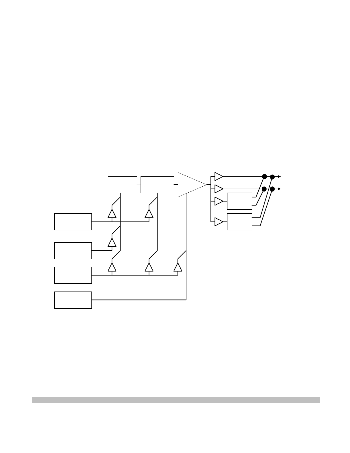
enters sustain phase, during which the envelope stays at the sustain level. Whenever a key-off occurs, the envelope
immediately enters a release phase during which the value linearly ramps from the current value to zero. When zero is
reached, the envelope value remains at zero.
Modulation of pitch and filter cutoff are in octaves, semitones, and cents. These parameters can be modulated to varying
degree, either positively or negatively, by the modulation envelope. The degree of modulation is specified in cents for the
full-scale attack peak.
The volume envelope operates in dB, with the attack peak provid ing a full scale output, appropriately scaled by the initial
volume. The zero value, however, is actually zero gain. The implementation in the EMU8000 provides for 96 dB of
amplitude control. When 96 dB of attenuation is reached in the final gain amplifier, an abrupt jump to zero gain (infinite dB
of attenuation) occurs. In a 16-bit system, this jump is inaudible.
9.1.8 Modulation Interconnection Summary
The following diagram shows the interconnections expressed in the SoundFont 2 specification synthesis model:
Oscillator Filter Amplifier
Pitch Fc Volume
Modulation
Envelope
Reverb
Chorus
Vibrato
LFO
Modulation
LFO
Volume
Envelope
Figure 2: Generator Based Modulation Structure
9.2 MIDI Functions
The response to certain MIDI commands is defined within the MIDI specification, and is therefore not considered to be part
of the SoundFont 2 specification. These MIDI commands may not be used as sources for the Modulator implementation.
For completeness, the expected responses are given here.
Specification Version 2.00b Note:
SoundFont 2.01 Technical Specification - Page 48 - Printed 12/10/1996 5:57 PM

• MIDI Key Number to Pitch, noted here in the 2.00a version of this specification, is the “Scale Tune” parameter in the
Generator list, is also considered a true Modulator and is therefore removed from this list.
• MIDI Pitch Bend, noted here in the 2.00a version of this specification, is considered a true Modulator and is therefore
removed from here.
MIDI CC0 Bank Select - When received, the following program change should select the MIDI program in this bank value
instead of the default bank of 0.
MIDI CC6 - Data Entry MSB - When received, its value should be sent to either the RPN or NRPN implementation
mechanism depending on the Data Entry mode.
MIDI CC32 Bank Select LSB - When received, may behave in conjunction with CC0 Bank Select to provide a total of
16384 possible MIDI banks of programs.
MIDI CC38 Data Entry LSB - When received, its value should be sent to either the RPN or NRPN implementation
mechanism, depending on the Data Entry mode.
MIDI CC64 Sustain - ACTIVE when greater than or equal to 64. When the sustain function is active, all notes in the keyon state remain in the key-on state regardless of whether a key-off command for the note arrives. The key-off commands
are stored, and when sustain becomes inactive, all stored key-off commands are executed.
MIDI CC66 Soft - ACTIVE when greater than or equal to 64. When active, all new key-ons are modulated in such a way to
make the note sound “soft.” This typically affects initial attenuation and filter cutoff is a pre-defined manner.
MIDI CC67 Sostenuto - ACTIVE when greater than or equal to 64. When sostenuto becomes active, all notes currently in
the key-on state remain in the key-on state until the sostenuto becomes inactive. All other notes behave normally. Notes
maintained by sostenuto in key-on state remain in key-on state even if sustain is switched on and off.
MIDI CC98 NRPN LSB - When received, should be processed by the NRPN implementation mechanism.
MIDI CC99 NRPN MSB - When received, should put the synthesizer in NRPN Data Entry mode and then should be
processed by the NRPN implementation mechanism.
MIDI CC100 RPN LSB - When received, should be processed by the RPN implementation mechanism.
MIDI CC101 RPN MSB - When received, should put the synthesizer in RPN Data Entry mode and then should be
processed by the RPN implementation mechanism.
MIDI CC120 All Sound Off - When received with any data value, all notes playing in the key-on state bypass the release
phase and are shut off, regardless of the sustain or sostenuto positions.
MIDI CC121 Reset All Controllers – Defined as Reset All Controllers as defined by the MIDI specification. This typically
resets the values of the MIDI continuous controllers to a power-on or default state.
MIDI CC123 All Notes Off - When received with any data value, all notes playing in the key-on state immediately enter
release phase, pending their status in SUSTAIN or SOSTENUTO state.
9.3 Parameter Units
The units with which SoundFont generators are described are all well defined. The strict definitions appear below:
ABSOLUTE SAMPLE DATA POINTS - A numeric index of 16 bit sample data point words as stored in ROM or supplied
in the smpl-ck, indexing the first sample data point word of memory or the chunk as zero.
SoundFont 2.01 Technical Specification - Page 49 - Printed 12/10/1996 5:57 PM

RELATIVE SAMPLE DATA POINTS - A count of 16 bit sample data point words based on an absolute sample data point
reference. A negative value implies a relative count toward the beginning of the data.
ABSOLUTE SEMITONES - An absolute logarithmic measure of frequency based on a reference of MIDI key numbers. A
semitone is 1/12 of an octave, and value 69 is 440 Hz (A-440). Negative values and values above 127 are allowed.
RELATIVE SEMITONES - A relative logarithmic measure of frequency ratio based on units of 1/12 of an octave, which is
the twelfth root of two, approximately 1.059463094.
ABSOLUTE CENTS - An absolute logarithmic measure of frequency based on a reference of MIDI key number scaled by
100. A cent is 1/1200 of an octave, and value 6900 is 440 Hz (A-440). Negative values and values above 12700 are
allowed.
RELATIVE CENTS - A relative logarithmic measure of frequency ratio based on units of 1/1200 of an octave, which is the
twelve hundredth root of two, approximately 1.000577790.
ABSOLUTE CENTIBELS - An absolute measure of the attenuation of a signal, based on a reference of zero being no
attenuation. A centibel is a tenth of a decibel, or a ratio in signal amplitude of the two hundredth root of 10, approximately
1.011579454.
RELATIVE CENTIBELS - A relative measure of the attenuation of a signal. A centibel is a tenth of a decibel, or a ratio in
signal amplitude of the two hundredth root of 10, approximately 1.011579454.
ABSOLUTE TIMECENTS - An absolute measure of time, based on a reference of zero being one second. A timecent
represents a ratio in time of the twelve hundredth root of two, approximately 1.011579454.
RELATIVE TIMECENTS - A relative measure of time ratio, based on a unit size of the twelve hundredth root of two,
approximately 1.011579454.
ABSOLUTE PERCENT - An absolute measure of gain, based on a reference of unity. In SoundFont 2, absolute percent is
measured in 0.1% units, so a value of zero is 0% and a value of 1000 is 100%.
RELATIVE PERCENT - A relative measure of gain difference. In SoundFont 2, relative percent is measured in 0.1% units.
When the gain goes below zero, zero is assumed; when the gain exceeds 100%, 100% is used.
9.4 The SoundFont Generator Model
Five kinds of Generator Enumerators exist: Index Generators, Range Generators, Substitution Generators, Sample
Generators, and Value Generators.
The following is the precedence of SoundFont generator in the SoundFont file format hierarchy.
• A ‘generator’ sets or offsets the value of a destination or a synthesis parameter. In exception cases, it sets ranges
(Range Generators), or sets values and never offsets values (Index Generators, Sample Generators, and
Substitution Generators).
• A generator is defined as identical to another generator if its generator operator is the same in both generators.
• A generator in a global instrument zone that is identical to a default generator supersedes or replaces the default
generator.
• A generator in a local instrument zone that is identical to a default generator or to a generator in a global
instrument zone supersedes or replaces that generator.
SoundFont 2.01 Technical Specification - Page 50 - Printed 12/10/1996 5:57 PM

• Points below (until noted) apply to Value Generators ONLY.
• A generator at the preset level adds to a generator at the instrument level if both generators are identical.
• A generator in a global preset zone that is identical to a default generator or to a generator in an instrument adds
to that generator.
• A generator in a global preset zone which is not identical to a default generator and is not identical to a generator
in an instrument has its effect added to the given synthesis parameter.
• A generator in a local preset zone that is identical to a generator in a global preset zone supersedes or replaces
that generator in the global preset zone. That generator then has its effects added to the destination-summing
node of all zones in the given instrument.
• A generator in a local preset zone which is not identical to a default generator or a generator in a global preset
zone has its effects added to the destination summing node of all zones in the given instrument.
• If the generator operator is a Range Generator, the generator values are NOT ADDED to those in the instrument
level, rather they serve as an intersection filter to those key number or velocity ranges in the instrument that is
used in the preset zone.
If the generator operator is a Substitution Generator or a Sample Generator, they are illegal at the preset level.
•
The only Index Generator legal at the Preset Level is ‘instrumentID’, whereas the only Index Generator legal at
the Instrument Level is ‘sampleID’
9.5 The SoundFont Modulator Controller Model
SoundFont Modulators are used to allow real-time control over the sound in sound designer programmable manner. Each
instance of a SoundFont modulator structure defines a real-time perceptually additive effect to be applied to a given
destination or synthesizer parameter.
9.5.1 Controller Model Theory of Operation
The SoundFont Modulator Controller model is a general-purpose mechanism intended to allow for flexible and complex
real-time control over the synthesis parameters provided. While SoundFont 2.00 provides a mechanism to set initial
conditions for a wide variety of synthesis parameters or generators at multiple levels of hierarchy (Preset/Instrument level,
Global/Local zones, etc.), the addition of the SoundFont Modulator Controller Model provides a mechanism to allow realtime control over those same parameters at the same levels of hierarchy.
The SoundFont Modulator Controller model is what it takes to turn the rather simplistic generator based synthesis model
into a complex and much more interesting synthesis model.
The following diagram shows the general nature the SoundFont controller model:
SoundFont 2.01 Technical Specification - Page 51 - Printed 12/10/1996 5:57 PM
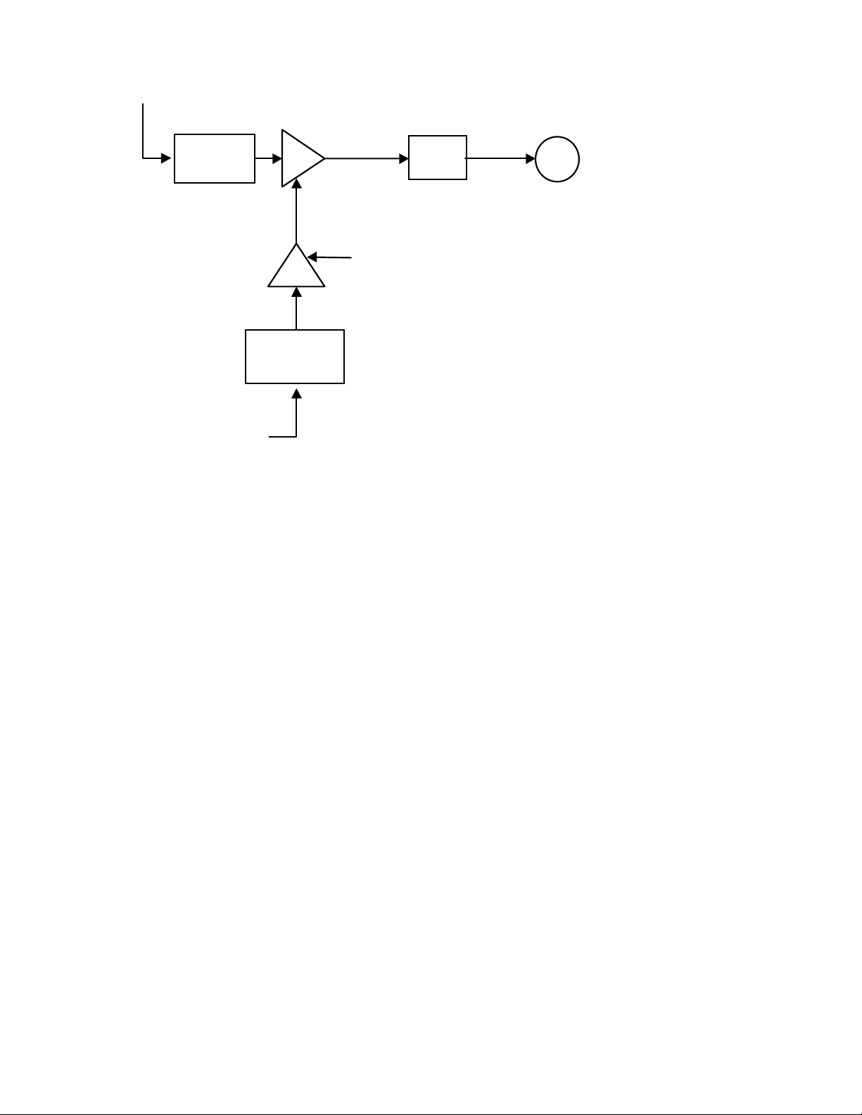
Primary Source
Norm
Norm
T
+
Generator,
Transform
or Destination
Summing
Node
Amount
Secondary or
Amount Source
Figure 3: SoundFont Modulator Building Block
The Primary Controller source is to be mapped into the -1 to 1 space based upon the controller direction and controller type.
The secondary controller source is also to be mapped into the -1 to 1 space based upon its controller direction and controller
type. The result of the secondary controller source input should be multiplied by the given amount, and that value should be
multiplied by the primary controller source mapped value. This value should then be fed into a transform, which should be a
mathematical expression which knows of no minimum or maximum amounts, and the result of this transformation should be
added to the destination summing node.
In simpler terms, the equation for a given destination summing node is:
destination value += Transform(Amount * Map(primary source input) * Map(secondary source input))
where Map(x) takes maps the source input value from -1 to 1 based on the source type, polarity and direction.
The diagram below shows this pictorially using the above control model diagram.
SoundFont 2.01 Technical Specification - Page 52 - Printed 12/10/1996 5:57 PM

Primary Source
I n p ut to
tra n s f orm is in
destination units
Output of
tra n s f o rm is in
destination units
Input value in
native units
Input value mappe d to a
value f r om -1 to 1
Input value ma ppe d to a
value from -1 to 1
A mount Source
Norm
T
Transform
A mount
Am o u nt va lue in the
units of the
Norm
destination.
Secondary or
Input value in
native units
Figure 4: Detailed SoundFont Modulator Building Block
+
Destination Summing
Node
The destination summing node consists of the sum of all given modulators with that destination as well as the effect of the
preset level of the SoundFont articulation data. This summed value should be added to the value as defined in the instrument
level of the SoundFont articulation data.
A few points of note here.
First, the SoundFont controller model makes no assumptions about the nature of the controller. So, for example, MIDI
controller values 0 to 127 are not mapped directly to synthesis parameters. MIDI controllers are simply a mechanism
designed to transmit information. The SoundFont controller model is
data values, rather the MIDI controller values should be translated to accommodate the SoundFont controller model. The
same would be true for any other possible controller source (such as a software LFO or a system timer). This makes the
controller model general purpose in nature.
Secondly, transform inputs are always in perceptually additive real-world units. Therefore transforms may only be simple
mathematical equations which know of no upper or lower limits to their potential values.
Third, with the exception of the file format size limits, there is no limit as to how many modulators may be put into the
SoundFont file format, or where in the hierarchy a SoundFont modulator may be placed. As a result, there is no limit as to
how many times a given destination may be affected by a given modulator source. Also, there is no limit as to how many
ways a given destination may be affected by a modulator source. Also there is no limit as to how many destinations may be
SoundFont 2.01 Technical Specification - Page 53 - Printed 12/10/1996 5:57 PM
NOT designed to accommodate the MIDI controller

affected by a single source, whether that source is used as a primary or as a secondary source. Again, to make the controller
model general in nature.
Fourth, in case it is not clear in the general description of the SoundFont hierarchy, the following is the precedence of
SoundFont modulators in the hierarchy.
• The ranges that modulators are active are defined in the Generator list, which is referenced by the same Bag
structure from which the modulator list is indexed.
• A series of Modulators modifies the value of a destination in the following manner:
Destination = Generator Value + Mod() + Mod() + Mod().
Where Mod(source, dest, amount source, transform) = Transform(source * amount * amount source)
IE Initial Attenuation = Generator 48 + Mod(source=CC7, dest=48) + Mod (source=CC11, dest=48) + ...
• A Modulator is defined as identical to another modulator if its source, destination, amount source, and transform
are the same in both modulators.
• The result of a modulator “adding to” another modulator equivalent to the result of a single modulator whose the
amount is the sum of the amounts in the two modulators which are “added”. In other words Mod((amount = a +
b)) = Mod(amount = a) + Mod(amount = b). This operation is only legal if both modulators are identical.
• All Modulators applied to a Destination need not be identical, however if two or more modulators applied to a
destination are not identical, their amounts may NOT be summed into a single modulator.
• A modulator, contained within a global instrument zone, that is identical to a default modulator supersedes or
replaces the default modulator.
• A modulator in a global instrument zone with the same destination but different source or transform parameters
has its effects added to the destination.
• A modulator, that is contained in a local instrument zone, which is identical to a default modulator or to a
modulator in a global instrument zone supersedes or replaces that modulator.
• A modulator in a local instrument zone with the same destination but different source or transform parameters
has its effects added to the destination.
• A modulator at the preset level adds to a modulator at the instrument level if both modulators are identical.
Otherwise, the effects of a modulator at the preset level are added to the effects of a modulator at the instrument
level.
• A modulator, contained within a global preset zone, that is identical to a default modulator or to a modulator in
an instrument adds to that modulator.
• A modulator in a global preset zone in an preset which is not identical to a default modulator and is not identical
to a modulator in an instrument has its effect added to the given destination.
• A modulator, contained within a local preset zone, that is identical to a modulator in a global preset zone
supersedes or replaces that modulator in the global preset zone. That modulator then has its effects added to the
destination summing node of all zones in the given instrument.
• A modulator in a local preset zone which is not identical to a default modulator or a modulator in a global preset
zone has its effects added to the destination summing node of all zones in the given instrument.
Finally, since the amount value must match the units of the destination, and since the controller model requires all units to
be of a perceptually additive nature, new generators and destinations that follow this revision of the specification must take
on perceptually additive units as well.
SoundFont 2.01 Technical Specification - Page 54 - Printed 12/10/1996 5:57 PM
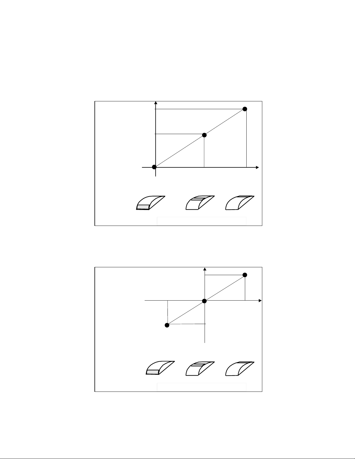
9.5.2 Pictorial Examples of Source Types
In order to make the concept of the source types, directions, and polarities perfectly clear, the following pictorial examples
are provided.
Figure 5 below shows the response to a Positive Unipolar Linear Source:
1
SoundFont
Modulator
Input
1/2
Values
0
Min
Mid = (Max+Min)/2
Controller Source Native Values
Figure 5: Positive Unipolar Linear Plot
(type=0, D=0, P=0)
Figure 6 below shows the response to a Positive Bipolar Linear Source:
1
SoundFont
Modulator
Input
0
Values
-1
Min
Mid = (Max+Min)/2
Max
Max
Controller Source Native Values
Figure 6: Positive Bipolar Linear Plot
(type=0, D=0, P=1)
SoundFont 2.01 Technical Specification - Page 55 - Printed 12/10/1996 5:57 PM
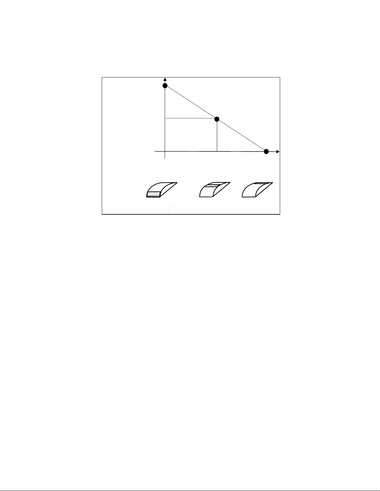
Note the difference caused by flipping the ‘P’ bit is a change in the “bias”, as well as cutting the resolution of the source
controller in half.
Figure 7 below shows the response of a Negative Unipolar Linear source:
1
SoundFont
Modulator
Input
1/2
Values
0
Min
Mid = (Max+Min)/2
Controller Source Native Values
Figure 7: Negative Unipolar Plot
(type=0, D=1, P=0)
Note the difference caused by flipping the ‘D’ bit is a change in the slope, or a mirror image of the original controller.
Likewise, a Negative Bipolar Linear plot would have a negative slopping bipolar characteristic.
The concave curves take on similar characteristics.
The figure below contains a summary of the approximate shapes of all supported controller types.
Max
SoundFont 2.01 Technical Specification - Page 56 - Printed 12/10/1996 5:57 PM
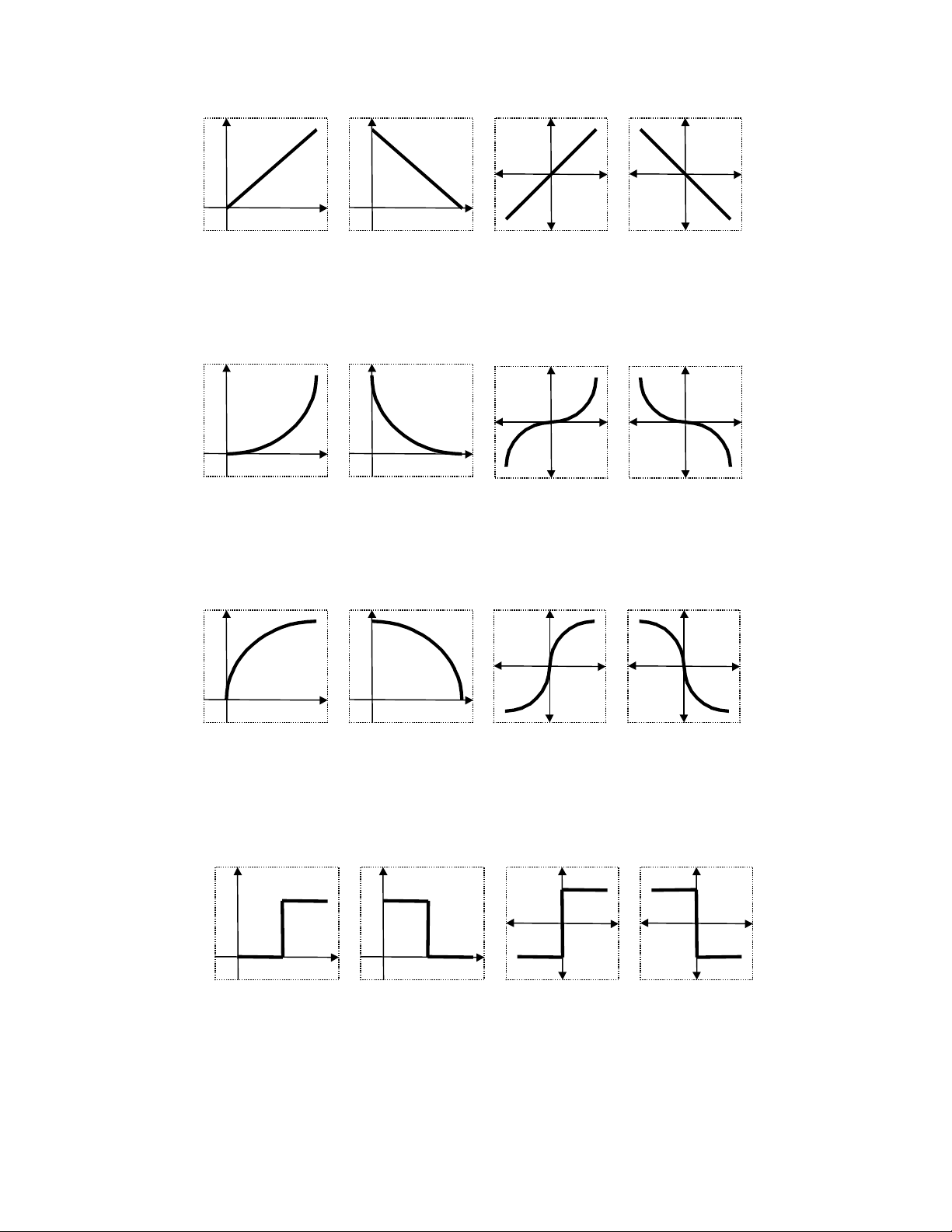
Positive Unipolar
N
N
r
N
r
N
r
N
r
N
r
N
r
N
r
egative Unipolar Positive Bipolar
Linear Controller Curves
for given Directions and Polairities
egative Bipola
Positive Unipolar
Positive Unipolar
egative Unipola
Concave Controller Curves
for given Directions and Polairities
egative Unipola
Convex Controller Curves
for given Directions and Polairities
Positive Bipolar
Positive Bipolar
egative Bipola
egative Bipola
Positive Unipolar
Figure 8: SoundFont Modulator Source Summary
egative Unipola
Switch Controller Curves
for given Directions and Polairities
Positive Bipolar
egative Bipola
SoundFont 2.01 Technical Specification - Page 57 - Printed 12/10/1996 5:57 PM

9.5.3 Mappings of Modulator Sources to the SoundFont Controller Input Domain
The following table shows how SoundFont modulator sources are mapped to the SoundFont controller minimum and
maximum values.
Note that due to the fact that MIDI has an even number of distributed points in their controllers, the maximum position can
not correspond to exactly 1.
Modulator Source Native Position SoundFont Mapped
Unipolar Position
SoundFont Mapped
Bipolar Position
7 bit MIDI Controller Min 0 0 -128/128 = -1
Data Value Max 127 127/128 = +0.992 127/128 = +0.992
14 bit MIDI Controller Min 0 0 -8192/8192 = -1
Data Value Max 8191 8191/8192 = 0.99999 8191/8192 = 0.99999
Table 2: Controller Native to Input Value Mappings
9.5.4 Linked Modulator Description
As stated before, the destination (sfModDestOper) enumeration may be one of two styles. It is either a SoundFont
Generator, as used in the IGEN or PGEN chunks, or it is a link to the source of another modulator. The latter allows the
“chaining” of two modulators together to produce an enhanced effect.
The following is a pictorial example of this:
Modulator 1
Modulator 2
Modulator 3
Figure 9: SoundFont Modulator Chaining
In this case, Modulator 1 is the 1
(Mod[Bag->wModNdx + 1]) and Modulator 3 is the 3
st
modulator in a list (Mod[Bag->wModNdx + 0]), Modulator is the 2nd modulator in a list
rd
modulator in that list (Mod[Bag->wModNdx + 2]), where Bag is
the zone designator (IBag, PBag) and Mod is the modulator data structure (IMod, PMod). The value of the Destination field
of both Modulator 1 and Modulator 2 is 0x8000 bitwise or’ed with 2. The rationale is that the top bit says the destination is
NOT a SoundFont Generator, rather it is a link, and the value of 2 is chosen because it is the THIRD modulator in the list
for the given zone for the given object (instrument or preset).
SoundFont 2.01 Technical Specification - Page 58 - Printed 12/10/1996 5:57 PM

Note that the destination is still a summing node, so multiple modulators may be linked to a single modulator. Also note that
the chains are not fixed to two links, Modulator 3 may be linked to yet another modulator. Circular references are illegal and
therefore should be detected by the SoundFont loader and all modulators in the circular reference are ignored. Also note that
order of the modulators in the list is irrelevant. Just as Modulators 1 and 2 are linked to 3, Modulators 2 and 3 could have
been linked to 1.
The source value of Modulator 3 has the value ‘link’, simply meaning that it expects it data to be fed to it by another
modulator and NOT by a user or synthesizer generated event. From Modulator 3, one cannot tell what modulators are
actually linked to it, the entire list of Modulators are scanned to decipher this.
9.6 SoundFont 2.01 Standard NRPN Implementation
Although the SoundFont 2.01 Modulator implementation gives a large degree of flexibility to real-time control over sounds,
by itself it precludes the ability to have some dynamic real-time control over the suite of synthesis parameters without
having to do sound design or customization. Therefore this NPRN implementation will be a standard NRPN implementation
to be used in any SoundFont 2.01 compatible synthesizer.
NRPN stands for Non Registered Parameter Number. The MIDI specification has defined this series of continuous
controllers to permit General MIDI compatible synthesizers to take advantage of their proprietary hardware by using these
messages to control the non-General MIDI compatible aspects of their hardware. The SoundFont 2.01 specification uses
these messages to allow arbitrary real-time control over all SoundFont synthesis parameters.
This specification outlines a general approach on how to select generators and what resolutions they may be controlled. This
way, there need not be any adjustments to this portion of the specification in order to accommodate new generators.
Note that this NRPN implementation is not compatible with NRPN implementations provided with other SoundFont 2.0
compatible products such as Creative Labs Sound Blaster AWE32.
9.6.1 The NRPN Message
A NRPN message is a series of standard Continuous Controller messages, which are order dependent. A maximum of 4
messages is necessary to complete a single NRPN message. The NRPN message format allows the use of the same 4
controllers to control an infinite number of parameters.
The Continuous Controller Messages that make up a NRPN message (in order) are as follows:
NRPN SELECT MSB: Continuous controller 99
NRPN SELECT LSB: Continuous controller 98
DATA ENTRY LSB: Continuous controller 38
DATA ENTRY MSB: Continuous controller 6
A NRPN message follows the running-status paradigm. In other words, if a NRPN SELECT LSB is received, it should be
used in conjunction with the most recently sent NRPN SELECT MSB, regardless of whether the MSB command was the
most previously sent message. The same goes for the other messages.
9.6.2 The NRPN Select Values
The SoundFont 2.01 standard defines the following values that must be recognized and responded to by any synthesizer that
is SoundFont 2.01 compatible. These values should not conflict with values used in standard and/or widely available MIDI
synthesizers today.
The NRPN Select MSB message value is 120. This message indicates that a NRPN Message that follows will be a
SoundFont 2.01 NRPN message.
SoundFont 2.01 Technical Specification - Page 59 - Printed 12/10/1996 5:57 PM

The NRPN Select LSB message with data less than 100 corresponds to the generator enumeration value, modulo 100, if and
only if the most recently sent NRPN Select MSB message was 120. The NRPN Select LSB message with data greater than
or equal to 100 is used to permit selecting of generator values greater than 100.
0 – 99: Indicates the generator value
100: Indicates a single multiple of 100 for generator value selection
101: Indicates a single multiple of 1,000 for generator value selection
102: Indicates a single multiple of 10,000 for generator value selection
103 – 127: Undefined, unused, should be ignored if encountered
Note that NRPN Select LSB greater than 100 are for setup only, and should not be used on their own in order to select a
generator parameter.
So, to have a NRPN message control the Initial Filter Cutoff parameter, the following NRPN Select parameters are sent:
NRPN Select MSB: 120
NRPN Select LSB: 8
And, if a generator value is defined by the SoundFont Specification with a value of 100, the following NRPN Select
parameters are sent:
NRPN Select MSB: 120
NRPN Select LSB: 100
NRPN Select LSB: 0
And, if a generator value is defined by the SoundFont Specification with a value of 250, the following NRPN Select
parameters are sent:
NRPN Select MSB: 120
NRPN Select LSB: 100 (generator 100)
NRPN Select LSB: 100 (generator 200)
NRPN Select LSB: 50 (generator 250)
Running status does not include multiple sends of values greater than 100. IE you cannot use a single message to select 251
if the most recently sent message selected generator 250:
NRPN Select LSB: 100
NRPN Select LSB: 100
NRPN Select LSB: 50 (Selects generator 250)
NRPN Select LSB: 51 (Selects generator 51, NOT 251)
If a parameter is selected which is unrecognized, or is not designated as a real-time controller or synthesizer parameter (such
as overriding root key, key number, etc), or cannot be controlled in real-time by a synthesizer, either at all or without
causing audio artifacts, the LSB selection should be ignored but the status of the MSB selection, being that of a SoundFont
2.01 NRPN controller, should remain unchanged.
9.6.3 The Default Data Entry Ranges
The Data Entry values, which follow the NRPN Select messages, have the following significance.
Data Entry values are ONLY applied as SoundFont 2.01 controllers if and only if the most recently sent NRPN MSB and
LSB message comprises a SoundFont 2.01 message AND an RPN LSB/MSB message combination was NOT sent more
recently than the SoundFont 2.01 NRPN LSB/MSB message.
SoundFont 2.01 Technical Specification - Page 60 - Printed 12/10/1996 5:57 PM

The Data Entry values are used to send an ADDITIVE response to a generator value, exactly the same as a modulator. Since
you have 2 controllers for a Data Entry message, the Data Entry values make up a single 14-bit value. The Data Entry value
is “applied” to a generator at the time the MSB message is sent in. In other words, when the MSB message is sent, this value
is combined with the most recently sent LSB message and then added to the appropriate generator value.
Data Entry values have zero-offset at 0x2000. This value always means add 0 or do not influence the parameter.
Data Entry value spans the “useful” range as outlined in section 8.1.3, and in the same perceptually-additive-real-world
units. In the case where the meaningful range consists of more than 8192 perceptually-additive-real-world units, the range
of the NRPN control of that parameter is decreased by a factor of two until the adjusted range consists of 8192 or less of the
perceptually-additive-real-world units. In the case where the meaningful range consists of less than 8192 perceptuallyadditive-real-world units, the range of the NRPN control of that parameter is left unchanged, and the synthesizer may or
may not permit the control to exceed that range.
9.7 On Implementation Accuracy
While the SoundFont 2 standard is well defined, it must be recognized that there are a large variety of practices and features
within the wavetable music synthesis industry that are not conducive to exact implementation of the specification as
defined. Some examples of impediments include the order of interpolation of sample data points, the exact shape and
number of segments of envelopes, the filter implementation, and the details of the implementation of loops.
Additionally, all real implementations are likely to have less accuracy than the SoundFont 2 standard itself. The units for
the standard have been chosen to exceed the accuracy required for high fidelity applications. It should be recognized that in
rendering a SoundFont 2 compatible file, a best practical reproduction is all that is expected.
As such, implementers of SoundFont 2 compatible rendering engines will have to determine based on their own perceptual
criteria the degree to which their implementation meets the standard. Approximations may take a variety of forms. In many
cases, the resolution of the rendering engine will be less than that of the corresponding SoundFont unit. Also, it will
frequently be the case that a line segment approximation will be made to a continuous curve. In the case of filters, the order
of the filter may vary from the SoundFont 2 standard, and an optimum audible equivalent will have to be heuristically
constructed. All such problems are left to the ingenuity of the implementers.
10 Error Handling
10.1 Structural Errors
Structural Errors are errors which are determined from the implicit redundancy of the SoundFont RIFF file structure, and
indicate that the structure is not intact. Examples are incorrect lengths for the chunks or sub-chunks, pointers out of valid
range, or missing required chunks or sub-chunks for which no error correction procedure exists.
In all cases, files should be checked for structural errors at load time, and if any are found the files should be rejected.
Separate tools or options can be used to “repair” structurally defective files, but these tools should validate that the
reconstructed file is not only a valid SoundFont compatible bank but also complies with the intended timbral results in all
cases.
10.2 Unknown Chunks
In parsing the RIFF structure, unknown but well formed chunks or sub-chunks may be encountered. Unknown chunks
within the INFO-list chunk should simply be ignored. Other unknown chunks or sub-chunks are illegal and should be
treated as structural errors.
SoundFont 2.01 Technical Specification - Page 61 - Printed 12/10/1996 5:57 PM

10.3 Unknown Enumerators
Unknown enumerators may be encountered in Generators, Modulator Sources, or Transforms. This is to be expected if the
ifil field exceeds the specification to which the application was written. Even if unexpected, unknown enumerators should
simply cause the associated Generator or Modulator to be ignored.
10.4 Illegal Parameter Values
Some SoundFont parameters are defined for only a limited range of the possible values which can be expressed in their
field. If the value of the field is not in the defined range, the parameter has an illegal value.
Illegal values for may be detected either at load or at run time. If detected at load time, the file may optionally be rejected as
structurally unsound. If detected at run time, the default value for the parameter should be used if the parameter is required,
or the entire Generator or Modulator ignored if it is optional. Certain parameters may have more specific procedures for
illegal values as expressed elsewhere in this specification.
10.5 Out-of-range Values
SoundFont parameters have a specified minimum and useful range the span the perceptually relevant values for the
associated sonic property. When the parameter value is exceeds this useful range, the parameter is said to have an out of
range value.
Out of range values can result from two distinct causes. An out of range value can be actually present as a SoundFont
generator value, or the out of range value can be the result of the summation of instrument and preset values.
Out of range values should be handled by substituting the nearest perceptually relevant or realizable value. SoundFont
compatible banks should not be created with out of range values in the instrument generators. While it is acceptable
practice to create SoundFont banks which produce out of range values as a result of summation, it is undesirable and should
be avoided where practical.
10.6 Missing Required Parameter or Terminator
Certain parameters and terminators are required by the SoundFont specification. If these are missing, the file is technically
not within specification. If such a problem is detected at load time, the file may optionally be rejected as structurally
unsound. If detected at run time, the instrument or zone for which the required parameter is missing should simply be
ignored. If this causes no sound, the corresponding key-on event is ignored.
10.7 Illegal enumerator
Certain enumerators are illegal in certain contexts. For example, key and velocity ranges must be the first generators in a
zone, instruments are not allowed in instrument zones, and sampleIDs are not allowed in preset zones. If such a problem is
detected at load time, the file may optionally be rejected as structurally unsound. If detected at run time, the enumerator
should simply be ignored.
11 Silicon SoundFonts
SoundFont 2.01 Technical Specification - Page 62 - Printed 12/10/1996 5:57 PM

11.1 Silicon SoundFont Overview
A “Silicon SoundFont Bank” is an implementation of a SoundFont compatible bank realized in non-volatile memory with
slight format additions. On initialization of a system using a Silicon SoundFont, the host processor navigates the Silicon
SoundFont ROM format in sample memory space, determines the number of SoundFont Banks installed, and, when
appropriate, reads the articulation data of the SoundFont files out of the Preset Data Chunks into its local RAM. The sample
headers in the Silicon SoundFont point to the sample address offsets relative to the start of the Sample Chunk in the
SoundFont compatible bank. The loader adds the appropriate offset to the sample addresses as part of its data management.
Then, the system operates like any other SoundFont compatible system.
The format of a Silicon SoundFont file intended to be burned into non-volatile memory is a hybrid between a standard ROM
header and a modification of the standard SoundFont compatible bank file format. The ROM header contains data used for
diagnostic tests, a ROM name, a size, and checksum information, and a sine wave sample to test audio outputs of a circuit.
This is the first block of data found in the SoundFont ROM (address 0). The structure of the data contained in the ROM
header is shown below.
Because sample memory space is word oriented, the endian nature of the resulting word reads is processor independent.
However, the organization of bytes within a word, or words within a doubleword may vary on both the way the data has
been encoded in the ROM and the endian nature of the processor. To handle all eventualities, it is recommended that the
initialization software both recognize and adapt for endian variations.
Note that SoundFont 2.04 introduces up to 24-bit sample data formats by splitting the sample pool into two chunks, one for
the upper 16-bits and one for the lower 8-bits. This was done to insure bi-directional compatibility; allowing older
synthesizers to take render SoundFont 2.04 files without modification. However, this format is no doubt difficult to render
in the form of wavetable ROM. It is the recommendation here that the pools be combined into a single pool, and wavetable
firmware be upgraded to account for this.
11.2 Silicon SoundFont ROM Header Format
typedef struct romHdrType{
DWORD romRsrc; // unused
DWORD romByteSize; // ROM size in bytes
CHAR interleaveIndex; // for use in case of interleaved ROMs
CHAR revision[3]; // for revision control
CHAR id[4]; // matched with the IROM chunk in SF file format
SHORT checksum; // to check ROM integrity
SHORT checksum2sComplement; // for updating checksum variable w/o changing file
// checksum value
CHAR bankFormat; // unused
CHAR product[16]; // product name (either system or SoundFont)
BYTE sampleCompType; // indicates type of sample precompensation used
CHAR filler1[2]; // future use
CHAR style[16]; // sound library style
CHAR copyright[80]; // copyright notice
DWORD sampleStart; // beginning byte address of the SoundFont bank
DWORD sineWaveStart; // beginning byte address of the sine wave sample
DWORD filler2[124]; // future use
SHORT sineWave[SINEWAVESIZE]; // sine wave sample data
} romHdr;
SoundFont 2.01 Technical Specification - Page 63 - Printed 12/10/1996 5:57 PM

12 Glossary
absolute - Describes a parameter which gives a definitive real-world value. Contrast to relative.
additive - Describes a parameter which is to be numerically added to another parameter.
articulation - The process of modulation of amplitude, pitch, and timbre to produce an expressive musical note.
articulation data – Single term indicating generators and modulators.
artifact - A (typically undesirable) sonic event which is recognizable as not being present in the original sound.
attack - That phase of an envelope or sound during which the amplitude increases from zero to a peak value.
attenuation - A decrease in volume or amplitude of a signal.
AWE32 - The original Creative Technology Sound Blaster product which contained an EMU8000 wavetable synthesizer
and supported the SoundFont standard.
bag - A SoundFont data structure element containing a list of zones.
balance - A form of stereo volume control in which both left and right channels are at maximum when the control is
centered, and which attenuates only the opposite channel when taken to either extreme.
bank - A collection of presets. See also MIDI bank.
bipolar - In the SoundFont standard, said of a modulator source whose minimum is -1 and whose maximum is 1. Contrast
“unipolar”
bi-directional compatibility - Simultaneous upward and downward compatibility. This refers to the fact that a properly
designed SoundFont compatible program can appropriately handle files written to either a lower or higher revision of the
specification.
big endian - Refers to the organization in memory of bytes within a word such that the most significant byte occurs at the
lowest address. Contrast “little endian.”
byte - A data structure element of eight bits without definition of meaning to those bits.
BYTE - A data structure element of eight bits which contains an unsigned value from 0 to 255.
case-insensitive - Indicates that an ASCII character or string treats alphabetic characters of upper or lower case as identical.
Contrast “case-sensitive.”
case-sensitive - Indicates that an ASCII character or string treats alphabetic characters of upper or lower case as distinct.
Contrast “case-insensitive.”
cent - A unit of pitch ratio corresponding to the twelve hundredth root of two, or one hundredth of a semitone,
approximately 1.000577790.
centibel - A unit of amplitude ratio corresponding to the two hundredth root of ten, or one tenth of a decibel, approximately
1.011579454.
CHAR - A data structure of eight bits which contains a signed value from -128 to +127.
chorus - An effects processing algorithm which involves cyclically shifting the pitch of a signal and remixing it with itself to
produce a time varying comb filter, giving a perception of motion and fullness to the resulting sound.
SoundFont 2.01 Technical Specification - Page 64 - Printed 12/10/1996 5:57 PM

chunk - The top-level division of a RIFF file.
convex - A curve which is bowed in such a way that it is steeper on its lower portion. Contrast with “concave” and “linear.”
concave - (1) A curve which is bowed in such a way that it is steeper on its upper portion. (2) In the SoundFont standard,
said of a modulator source whose shape is that of the amplitude squared characteristic. Contrast with “convex” and “linear.”
cutoff frequency - The frequency of a filter function at which the attenuation reaches a specified value.
data points - The individual values comprising a sample. Sometimes also called sample points. Contrast “sample.”
decay - The portion of an envelope or sound during which the amplitude declines from a peak to steady state value.
decibel - A unit of amplitude ratio corresponding to the twentieth root of ten, approximately 1.122018454.
delay - The portion of an envelope or LFO function which elapses from a key-on event until the amplitude becomes nonzero.
destination - The generator to which a modulator is applied.
DC gain - The degree of amplification or attenuation a system presents to a static or zero frequency signal.
digital audio - Audio represented as a sequence of quantized values spaced evenly over time. The values are called “sample
data points.”
doubleword - A data structure element of 32 bits without definition of meaning to those bits.
downloadable - Said of samples which are loaded from a file into RAM, in contrast to samples which are maintained in
ROM.
dry - Refers to audio which has not received any effects processing such as reverb or chorus.
DWORD - A data structure of 32 bits which contains an unsigned value from zero to 4,294,967,295.
EMU8000 - A wavetable synthesizer chip designed by E-mu Systems for use in Creative Technology products.
envelope - A time varying signal which typically controls the pitch, volume, and/or filter cutoff frequency of a note, and
comprises multiple phases including attack, decay, sustain, and release.
enumerated - Said of a data element whose symbols correspond to particular assigned functions.
extensible - Said of a format whose feature set can be expanded without impact on existing function.
flat - A. Said of a tone that is lower in pitch than another reference tone. B. Said of a frequency response that does not
deviate significantly from a single fixed gain over the audio range.
generator - In the SoundFont standard, a parameter which directly affects sound reproduction. Contrast with “modulator.”
global - Refers to parameters which affect all associated structures. See “global zone.”
global zone - A zone whose generators and modulators affect all other zones within the object.
header - A data structure element which describes several aspects of a SoundFont element.
hydra - A. A nine-headed mythical beast. B. The nine “pdta” sub-chunks which make up the SoundFont articulation data.
SoundFont 2.01 Technical Specification - Page 65 - Printed 12/10/1996 5:57 PM

instrument - In the SoundFont standard, a collection of zones which represents the sound of a single musical instrument or
sound effect set.
instrument zone - A sample and associated articulation data defined to play over certain key numbers and velocities.
interpolator - A circuit or algorithm which computes intermediate points between existing sample data points. This is of
particular use in the pitch shifting operation of a wavetable synthesizer, in which these intermediate points represent the
output samples of the waveform at the desired pitch transposition.
key number - See MIDI key number.
layer - An obsolete SoundFont term, now called a Preset Zone.
level - In the SoundFont structure, this refers either to the preset and preset zones (the preset level) or the instrument and
instrument zones (the instrument level.)
LFO - Acronym for Low Frequency Oscillator. A slow periodic modulation source.
linear - In the SoundFont standard, said of a modulator source whose shape is that of a straight line. Contrast with
“concave” and “convex.”
linear coding - The most common method of encoding amplitudes in digital audio in which each step is of equal size.
little endian - A method of ordering bytes within larger words in memory in which the least significant byte is at the lowest
address. Contrast “big endian.”
loop - In wavetable synthesis, a portion of a sample which is repeated many times to increase the duration of the resulting
sound.
loop points - The sample data points at which a loop begins and ends.
lowpass - Said of a filter which attenuates high frequencies but does not attenuate low frequencies.
modulator - In the SoundFont standard, a parameter which routes an external controller to dynamically alter the setting of a
“generator.” Contrast with “generator.”
monotonic - Continuously increasing or decreasing. Said of a sequence which never reverses direction.
MIDI - Acronym for Musical Instrument Digital Interface. The standard protocol for sending performance information to a
musical synthesizer.
MIDI bank - A group of up to 128 presets selected by a MIDI “change bank” command.
MIDI continuous controller - A construct in the MIDI protocol.
MIDI key number - A construct in the MIDI protocol which accompanies a MIDI key-on or key-off command and specifies
the key of the musical instrument keyboard to which the command refers.
MIDI pitch bend - A special MIDI construct akin to the MIDI continuous controllers which controls the real-time value of
the pitch of all notes played in a MIDI channel.
MIDI preset - A “preset” selected to be active in a particular MIDI channel by a MIDI “change preset” command.
MIDI velocity - A construct in the MIDI protocol which accompanies a MIDI key-on or key-off command and specifies the
speed with which the key was pressed or released.
modulator - In the SoundFont standard, a set of parameters which affect a particular generator. Contrast with “generator.”
SoundFont 2.01 Technical Specification - Page 66 - Printed 12/10/1996 5:57 PM

mono - Short for “monophonic.” Indicates a sound comprising only one channel or waveform. Contrast with “stereo.”
negative - In the SoundFont standard, said of a modulator which has a negative sloping characteristic. Contrast with
“positive.”
object - Either an instrument or a preset, depending on the context.
octave - A factor of two in ratio, typically applied to pitch or frequency.
orphan - Said of a data structure which under normal circumstances is referenced by a higher level, but in this particular
instance is no longer linked. Specifically, it is an instrument which is not referenced by any preset zone, or a sample which
is not referenced by any instrument zone.
oscillator - In wavetable synthesis, the wavetable interpolator is considered an oscillator.
pan - Short for “panorama.” This is the control of the apparent azimuth of a sound source over 180 degrees from left to
right. It is generally implemented by varying the volume at the left and right speakers.
pitch - The perceived value of frequency. Generally can be used interchangeably with frequency.
pitch shift - A change in pitch. Wavetable synthesis relies on interpolators to cause pitch shift in a sample to produce the
notes of the scale.
pole - A mathematical term used in filter transform analysis. Traditionally in synthesis, a pole is equated with a rolloff of
6dB per octave, and the rolloff of a filter is specified in “poles.”
positive - In the SoundFont standard, said of a modulator source which has a positive sloping characteristic. Contrast
“negative.”
Preditor - E-mu Systems’ proprietary SoundFont 2.00 compatible bank editing software.
preset - A keyboard full of sound. Typically the collection of samples and articulation data associated with a particular
MIDI preset number.
preset zone - A subset of a preset containing generators, modulators, and an instrument.
proximal - Closest to. Proximal sample data points are the data points closest in either direction to the named point.
Q - A mathematical term used in filter transform analysis. Indicates the degree of resonance of the filter. In synthesis
terminology, it is synonymous with resonance.
RAM - Random Access Memory. Conventionally, this term implies read-write memory. Contrast “ROM.”
record - A single instance of a data structure.
relative - Describes a parameter which merely indicates an offset from an otherwise established value. Contrast to absolute.
release - The portion of an envelope or sound during which the amplitude declines from a steady state to zero value or
inaudibility.
resonance - Describes the aspect of a filter in which particular frequencies are given significantly more gain than others.
The resonance can be measured in dB above the DC gain.
resonant frequency - The frequency at which resonance reaches its maximum.
SoundFont 2.01 Technical Specification - Page 67 - Printed 12/10/1996 5:57 PM

reverb - Short for reverberation. In synthesis, a synthetic signal processor which adds artificial spaciousness and ambience
to a sound.
RIFF - Acronym for Resource Interchange File Format. The recommended form for interchange files such as SoundFont
compatible files within Microsoft operating systems.
ROM - Acronym for Read Only Memory. A memory whose contents are fixed at manufacture, and hence cannot be written
by the user. Contrast with RAM.
sample - This term is often used both to indicate a “sample data point” and to indicate a collection of such points comprising
a digital audio waveform. The latter meaning is exclusively used in this specification.
sample rate - The frequency, in Hertz, at which sample data points are taken when recording a sample.
semitone - A unit of pitch ratio corresponding to the twelfth root of two, or one twelfth of an octave, approximately
1.059463094.
sharp - Said of a tone that is higher in pitch than another reference tone.
SHORT - A data structure element of sixteen bits which contains a signed value from -32,768 to +32,767.
soft - The pedal on a piano, so named because it causes the damper to be lowered in such a way as to soften the timbre and
loudness of the notes. In MIDI, continuous controller #66 which behaves in a similar manner.
sostenuto - The pedal on a piano which causes the dampers on all keys depressed to be held until the pedal is released. In
MIDI, continuous controller #67, which behaves in a similar manner.
sustain - The pedal on a piano which prevents all dampers on keys as they are depressed from being released. In MIDI,
continuous controller #64, which behaves in a similar manner.
SoundFont - A registered trademark of E-mu Systems, Inc, indicating files, data, synthesizers, hardware or software
produced by E-mu that conform to the SoundFont Technical Specification.
SoundFont Compatible - Indicates files, data, synthesizers, hardware or software that conform to the SoundFont Technical
Specification.
source - In a SoundFont modulator, the enumerator indicating the particular real-time value which the modulator will
transform, scale, and add to the destination generator.
split - An obsolete SoundFont term. Please see “Instrument Zone”
stereo - Literally indicating three dimensions. In this specification, the term is used to mean two channel stereophonic,
indicating that the sound is composed of two independent audio channels, dubbed left and right. Contrast with monophonic.
sub-chunk - A division of a RIFF file below that of the chunk.
synthesis engine - The hardware and software associated with the signal processing and modulation path for a particular
synthesizer.
synthesizer - A device ideally capable of producing arbitrary musical sound.
terminator - A data structure element indicating the final element in a sequence.
timecent - A unit of duration ratio corresponding to the twelve hundredth root of two, or one twelve hundredth of an octave,
approximately 1.000577790.
SoundFont 2.01 Technical Specification - Page 68 - Printed 12/10/1996 5:57 PM

transform - In a SoundFont modulator, the enumerator indicating the particular transfer function through which the source
will be passed prior to scaling and addition to the destination generator.
tremolo - A periodic change in amplitude of a sound, typically produced by applying a low frequency oscillator to the final
volume amplifier.
triangular - A waveform which ramps upward to a positive limit, then downward at the opposite slope to the symmetrically
negative limit periodically.
unipolar - In the SoundFont standard, said of a modulator source whose minimum is 0 and whose maximum is 1. Contrast
with “bipolar.”
unpitched - Said of a sound which is not characterized by a perceived frequency. This would be true of noise-like musical
instruments and of many sound effects.
velocity - In synthesis, the speed with which a keyboard key is depressed, typically proportionally to the impact delivered
by the musician. See also MIDI velocity.
vibrato - A periodic change in the pitch of a sound, typically produced by applying a low frequency oscillator to the
oscillator pitch.
volume - The loudness or amplitude of a sound, or the control of this parameter.
wavetable - A music synthesis technique wherein musical sounds are recorded or computed mathematically and stored in a
memory, then played back at a variable rate to produce the desired pitch. Additional timbre adjustments are often made to
the sound thus produced using amplifiers, filters, and effect processing such as reverb and chorus.
WORD - A data structure of 16 bits that contains an unsigned value from zero to 65,535.
word - A data structure element of 16 bits without definition of meaning to those bits.
zone - An object and associated articulation data defined to play over certain key numbers and velocities.
SoundFont 2.01 Technical Specification - Page 69 - Printed 12/10/1996 5:57 PM
 Loading...