

Page 1
1
Page 2

2
SoundExpression
Page 3
Before You Begin your Installation
The product you have purchased is designed to be easily installed
into most IBM PC or compatible systems. Many products have large,
easy-to-read legends to allow for the easy configuring of the
product. This installation manual contains detailed instructions.
Most included software has automatic installation programs to place
the software correctly onto your computer. However, as all computers are configured
differently, you may be required to perform some basic DOS or Windows tasks. If you
are not familiar with basic DOS commands such as DIR, CD, or EDIT, you should
check your DOS manual, or seek assistance from you local computer dealer to install
the product.
3
How to get Technical Assistance
The dealer that you purchased this product or your computer
from is the first place you should go for technical assistance. The
dealer is usually the most qualified source of help, and is most
familiar with your system and how this product should be
installed. Many dealers have customer service and technical
support programs, with varying levels of support offered, depending on your needs
and computer knowledge. Please contact the dealer first whenever a problem occurs.
If your Dealer Can’t Assist you
If you can’t get assistance from your dealer, the manufacturer provides varying levels
of technical assistance as summarized on the following page.
Page 4
4
2
3
1
4
5
6
7
9
8
2
3
1
4
5
6
7
9
8
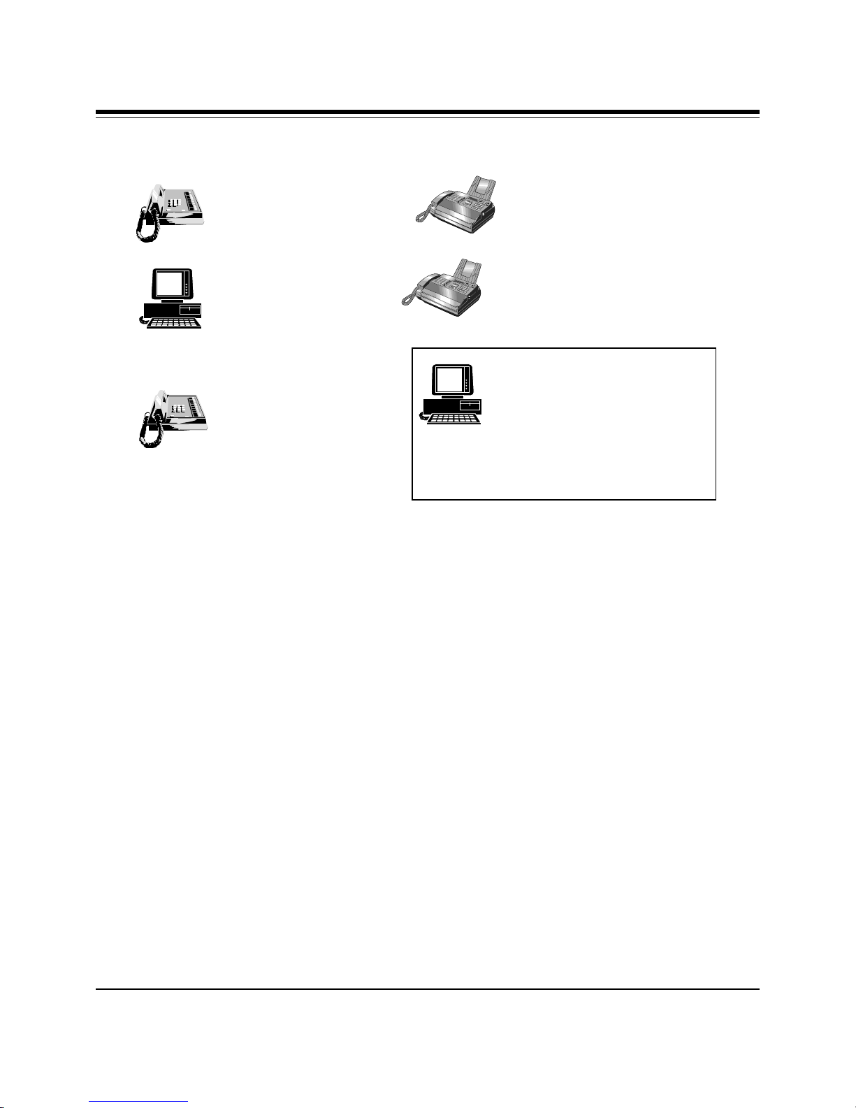
Technical Support
407-241-8088
Technical Support Fax
407-997-0918
Automated Fax Retrieval
Boca BBS
407-241-1601
System
407-995-9456
On-Line Support!
Priority Service
900-555-4900
($2 per minute)
The Standard Free Technical Support number is for quick answers to specific inquiries
on product features and technical questions (call 407-241-8088; M-F, 8 am to 6:30 pm
EST). Direct access to technical support representatives is provided on a limited basis.
CompuServe: GO BOCA
Internet:
email: [email protected]
on the World-wide WEB:
http://www.boca.org
If you require immediate attention or in-depth help with the installation of the product,
please call our 900-priority support number for service. This number gives you
immediate access to senior-level technicians. The number is 900-555-4900. You will be
charged $2.00 per minute. The charges will appear on your next phone bill.
Damaged or Missing Items
We use many world-class quality assurance programs to ensure the product you
purchased is of the highest caliber. Sometimes, however, a component may be missing
from the box, or is damaged or corrupt in some way. If this happens, immediately
return the entire package to your place of purchase so you may exchange it for a new
one. Your dealer should be able to provide you with an exchange far more quickly than
by contacting us directly. If for some reason you are unable to return the product
directly to its place of purchase, refer to the “Servicing Your Product” and “Warranty”
sections in this manual for instructions.
SoundExpression
Page 5

Contents
Section One: Introduction.......................................................................8
1.1 Summary of Features ............................................................................. 9
1.2 System Requirements............................................................................ 9
Section Two: Installing Your New SoundExpression .........................10
2.1 Replacing an Existing Sound Card................................................... 10
2.2 Replacing an Existing Modem........................................................... 10
2.3 Reviewing Board Connectors............................................................. 11
2.4 Connecting to an IDE CD-ROM Drive............................................ 12
2.5 Inserting the Board............................................................................... 13
5
2.6 Connecting for Modem Use ............................................................... 14
2.7 Attaching External Audio/Game Devices ....................................... 15
2.7.1 Attaching External Audio-In Devices ..................................... 15
2.7.2 Attaching External Audio-Out Devices.................................. 16
2.7.3 Attaching Joystick/MIDI Device.............................................. 17
2.8 Driver Installation for Windows 3.1/DOS Users .......................... 18
2.9 Driver Installation for Windows 95 Users...................................... 23
Section Three: Modem Functions and Features................................. 25
3.1 Introduction........................................................................................... 25
3.2 Testing the Connection........................................................................ 26
Section Four: Troubleshooting.............................................................27
Page 6

6
Appendix A: Technical Specifications ................................................ 33
Appendix B: Configuration Settings ................................................... 35
Appendix C: Microphone and Speaker Requirements ...................... 36
Appendix D: Wave Table Card Installation ......................................... 37
Appendix E: A Note on the MIDI Interface .......................................... 38
Appendix F: A Note on Digital Sound ................................................. 39
Appendix G: A Note on Windows Sound System .............................. 40
Appendix H: Compliance Information................................................. 41
Appendix I: Servicing Your Boca Product .......................................... 43
Appendix J: Warranty ........................................................................... 45
Appendix K: Modem Command Reference ........................................ 46
Basic AT Commands .................................................................................. 46
Extended AT Commands........................................................................... 48
MNP Operation .......................................................................................... 49
V.42/V.42bis .................................................................................................. 52
S-Registers ................................................................................................... 53
ATMS+ (Modulation Select) .................................................................... 57
Result Codes................................................................................................60
Appendix L: Glossary of Audio Terms ................................................ 63
Appendix M: Glossary of Modem Communications Terms ..............
64
SoundExpression
Page 7

7
Using The SoundExpression
Installation and User Guide
This manual provides installation and
operating instructions for this product.
The manual assumes you have basic
computer skills and are familiar with
personal computers. Its primary purpose
is to provide physical installation
instructions, instructions for configuring
the board, and basic troubleshooting.
Our customer support experience has
shown that many costly and timeconsuming calls to technical support staff
can be avoided with closer attention to
the information provided here. In
addition to following the instructions
provided in this manual, you will also
need to consult the documentation
supplied with your communications
software to make use of the card’s
modem functions. For Windows sound
applications, refer to the documentation
for your sound applications.
How This Manual is
Organized
Section One: Introduction. An overview
of the features of the SoundExpression,
along with system requirements.
Section Two: Installing Your New
SoundExpression. This section provides
a diagram of the SoundExpression board,
instructions on how to insert the board
into your system, as well as how to make
all connections to other devices.
Section Three: Modem Functions and
Features. Describes modem features and
provides procedures for testing the
modem’s connection.
Section Four: Troubleshooting. Provides
solutions to common problems for both
sound and modem functions.
Appendices. These include technical
specifications, configuration settings,
microphone and speaker requirements, as
well as instructions for installing a wave
table card. Notes on the MIDI interface,
digital sound, and Windows Sound
System are also included. A modem AT
command reference, modem and audio
glossaries, FCC and DOC (Canada)
compliance information, and service and
warranty policies complete this section.
Page 8
8
Section One: Introduction
The SoundExpression provides a Plug
and Play digital sound controller and IDE
CD-ROM interface for multimedia PC
applications. It also provides speaker
phone capability, integrated with a
modem for high-speed data and fax
communications and voicemail. This
unique design offers multiple
functionality all in a single-board
solution.
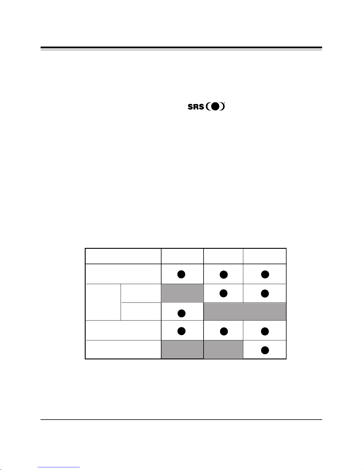
This manual covers three separate
models of the SoundExpression product.
Installation of all three products is
similar; only features differ as
highlighted in the chart below.
A Word about SRS® Retrieval
System...
The SoundExpression also supports
Sound Retrieval System. SRS
is rapidly becoming the standard for 3D
audio technology. It creates a threedimensional sound image from any audio
source with only two conventional stereo
speakers.
SoundExpression
Feature SE14SRS SE34SRS SE34SVD
Plug and Play
Max. 28.8Kbps
Modem
Speed: 14.4Kbps
SRS compatible
DSVD
Page 9

9
A Word about Digital Simultaneous
Voice and Data (DSVD)...
Digital Simultaneous Voice and Data
(DSVD) is a standard allowing the
simultaneous sharing of voice and data
over a single telephone line. With the
SE34SVD, you will be able to make
ordinary phone calls to other PC users
while sharing modem applications over a
standard telephone line. When a phone
call is in Digital SVD mode, any data
(e.g., images, 3D-graphics, shared
applications, interactive games) can be
shared with a normal phone conversation
over the same analog line.
1.1 Summary of Features
n Integrated sound controller
compatible with Sound Blaster Pro,
Ad Lib, and Microsoft Windows
Sound System.
n Plug and Play compatible
n Software enable/disable of game
(joystick) port.
n Unique 2-in-1 combination of data
communications and audio
applications.
n 28.8Kbps (SE34SRS/SE34SVD)
14.4Kbps (SE14SRS) fax/data/voice
modem with speaker phone and
16C550 UART.
n Class 1 & 2/Group 3 14.4Kbps send/
receive fax
n V.42 and MNP2-4 error control
n V.42bis and MNP5 data compression.
1.2 System Requirements
n IBM-compatible computer models 486
or Pentium (for SE34SRS and
SE34SVD); (minimum386/DX for
SE14SRS).
n 16- or 8-bit stereo and mono sound
n Sample rates up to 44.1KHz
n Built-in sound blaster-compatible
digital audio processor.
n Sound controller (software-
configurable only).
n Full-duplex speakerphone
n Software-enabled IDE CD-ROM
interface
n 4MB RAM minimum.
n VGA or SVGA display.
n 25MB of free hard disk space for
installing all software.
n Windows 3.1 enhanced mode (if you
intend to run games and applications
in Windows).
n DOS 5.0 or later.
Introduction
Page 10

10
Section Two: Installing Your
SoundExpression
This section explains how to install the
SoundExpression in your computer.
Non-Windows 95 Users
Windows 95 users may continue with
the next page.
2.2 Replacing an Existing Modem
If your computer came with an internal
modem, you must physically remove it or
disable it through your computer ’s BIOS
setup. Consult your computer manual’s
documentation for specific instructions.
Now, you are ready to install the
SoundExpression.
2.1 Replacing an Existing Sound Card
1. Turn on your computer and start
Windows, go to the Main group, select
Control Panel and select Drivers. Here
you will see a list of device drivers
present in your computer.
2. Remove the sound card drivers from
the drivers list. Highlight the sound
drivers and click on “remove.” If you
are not sure which drivers are for your
sound card, refer to the
documentation that came with your
sound card or your computer system.
3. Turn off your computer and remove
the sound card from the system.
NOTE for DOS Users... You may need to
remove certain drivers from your
CONFIG.SYS file when removing
existing devices.
SoundExpression
Page 11
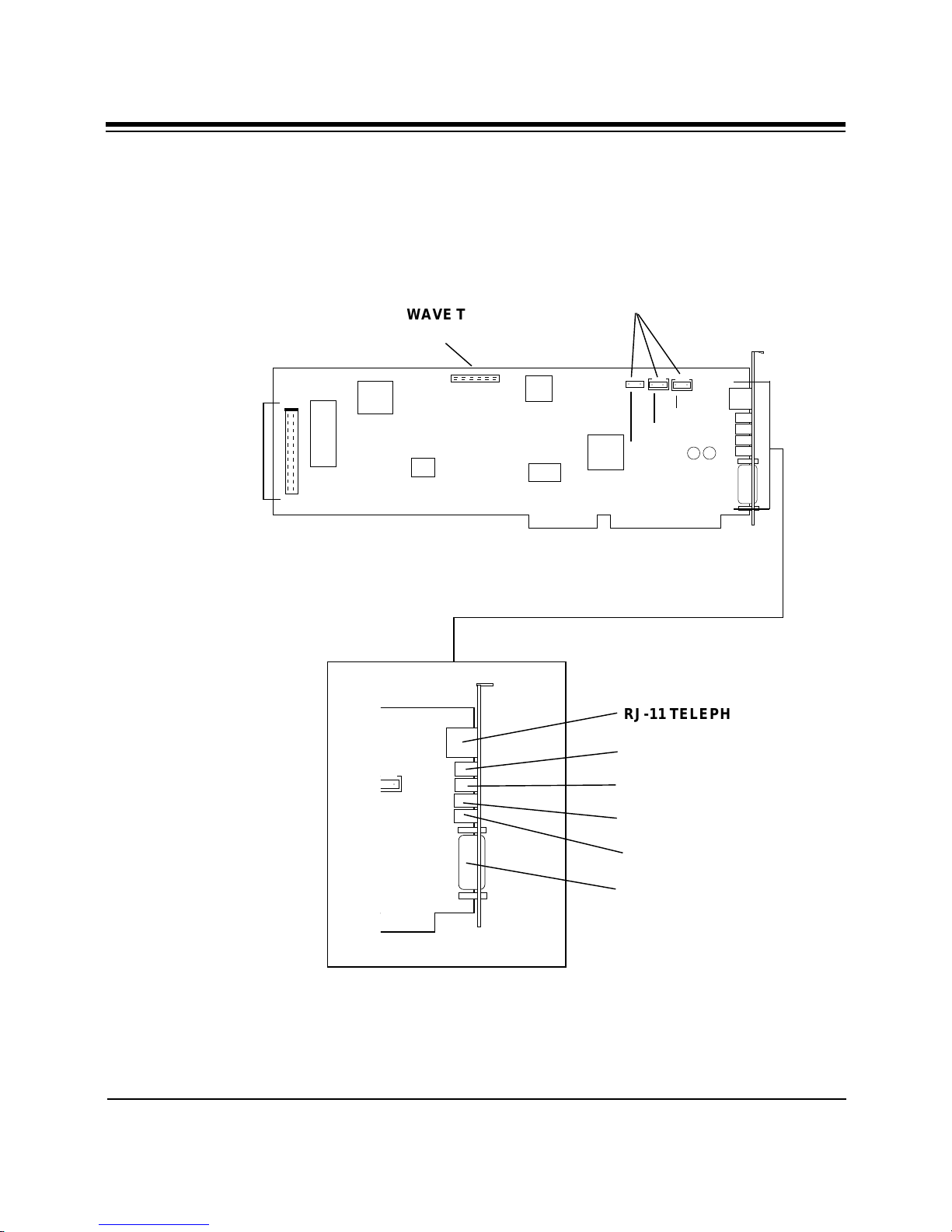
○ ○
○ ○
○ ○
WAVE TABLE
CONNECTOR
RJ-11 TELEPHONE JACK
MIC (microphone)
L-IN (LINE-IN)
L-OUT (LINE OUT)
SPK (speaker)
JOYSTICK/MIDI CONNECTOR
Connection to External Devices
Connection to Internal Devices
2.3 Reviewing Board Connectors
Mitsumi
Panasonic
Sony/IDE
CD-ROM AUDIO
INPUT CONNECTORS
IDE CD-ROM
INTERFACE
CONNECTOR
(white block
and “#1” show
pin 1)
Installing Your SoundExpression
11
Page 12
12
○ ○ ○
○ ○ ○
○ ○ ○ ○ ○
○ ○ ○ ○ ○
.
.
.
.
.
.
.
.
.
.
.
.
.
.
.
ð
CD-ROM audio cable
CD-ROM drive
(rear view)
SPK
L-OUT
L-IN
MIC
A white block and “#1” indicate Pin 1
colored stripe
pin
1
NOTE: Some CD-ROM drives have jumpers
for a “MASTER/SLAVE” configuration.
Make sure your CD-ROM drive is set for
“MASTER”.
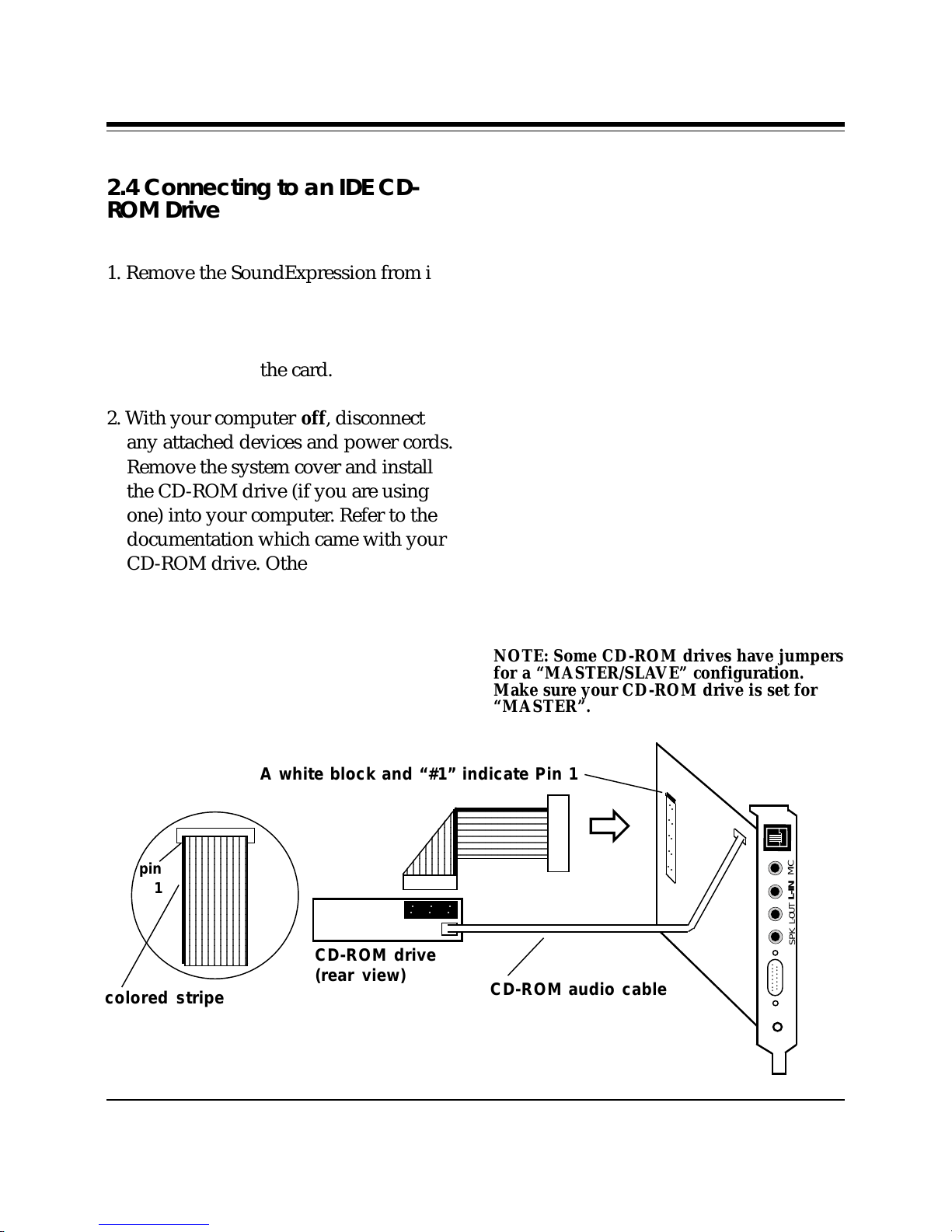
2.4 Connecting to an IDE CD-
ROM Drive
1. Remove the SoundExpression from its
anti-static bag, handling it by its edges
and retaining bracket. Be careful not to
touch the edge connector or any
components on the card.
2. With your computer off, disconnect
any attached devices and power cords.
Remove the system cover and install
the CD-ROM drive (if you are using
one) into your computer. Refer to the
documentation which came with your
CD-ROM drive. Otherwise, skip to 2.5
Inserting the Board.
3. When connecting your CD-ROM drive
(must be IDE type) to the
SoundExpression, connect the ribbon
interface cable from the CD-ROM drive
to the interface connector on the
SoundExpression before inserting the
board into your computer.
4. If an audio cable is included with your
CD-ROM drive, connect it from the
CD-ROM drive to the respective CDROM sound input connector for Sony,
Panasonic, and Mitsumi IDE CD-ROM
drives. Look for the connectors labeled
J11, J10, and J9 in the upper right
corner of the board. See illustration on
next page.
CAUTION: When connecting cables, be sure
that Pin 1 on the cable, usually marked with
a colored stripe (often red), matches up with
pin 1 on the board connector. A band on the
connector outline denotes Pin 1.
SoundExpression
Page 13
13
○ ○
○ ○
○ ○
.
.
.
.
.
.
.
.
.
.
.
.
.
.
.
SPK
L-OUT
L-IN
MIC
Sample system
è
. . . . . . . .
. . . .
R
L
R L
R L
MITSUMIPANASONIC
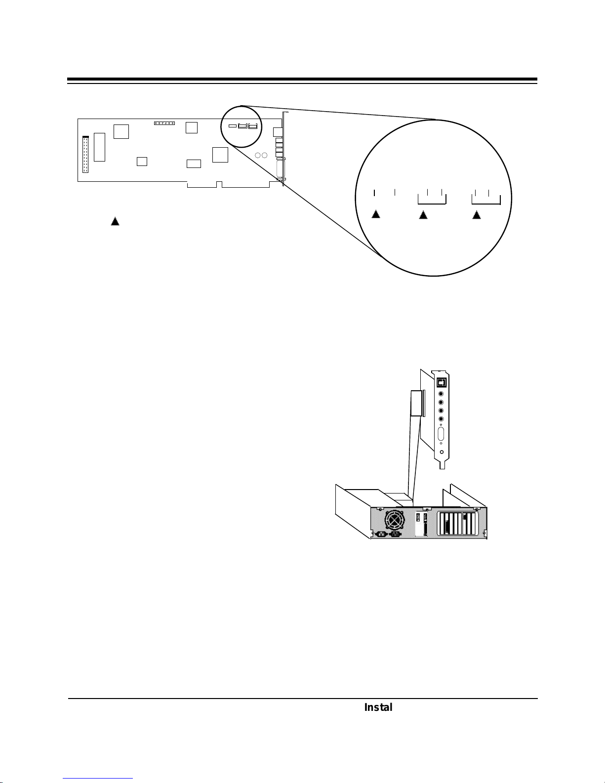
2.5 Inserting the Board
1. Locate an available 16-bit expansion
slot. Remove that expansion slot cover
and save the screw.
2. Carefully insert the SoundExpression
into the expansion slot you selected,
applying pressure to the upper board
edge until it snaps into place, being
careful not to disconnect any CD-ROM
or audio cables you may have
attached.
3. Secure the board into place by aligning
its metal retaining bracket with the
hole in the top edge of the system’s
rear panel. Fasten the modem’s metal
bracket with the screw removed in step
1.
NOTE: indicates pin 1 for each of the
audio connectors. “L” and “R” specify left
and right channel for each audio connector
type.
J11
J10
J9
SONY
Installing Your SoundExpression
Page 14
14
ð
PHONE
JACK
EXISTING
CABLE
RJ-SPLITTER
.
.
.
.
.
.
.
.
.
.
.
.
.
.
.
MIC
SPK
L-IN
L-OUT
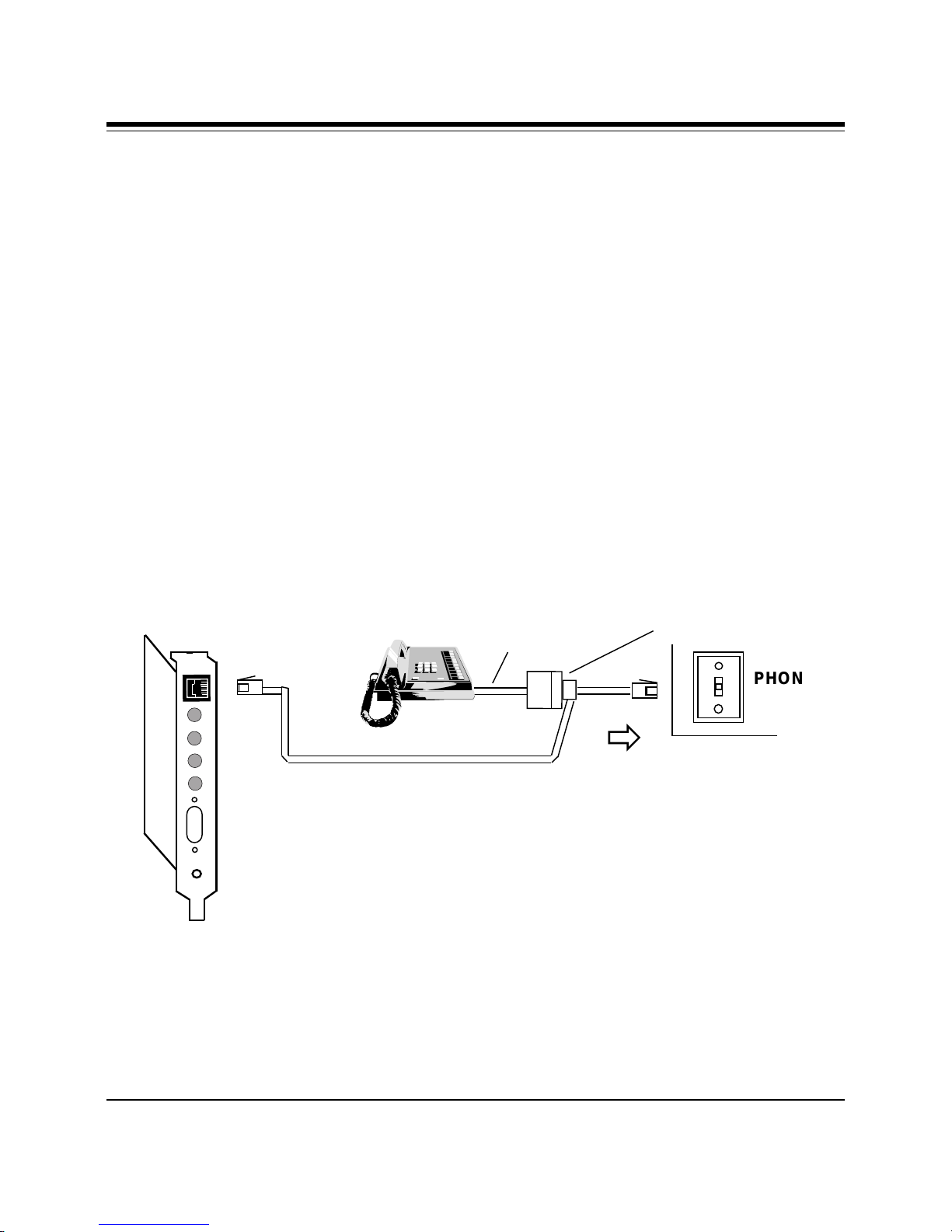
2.6 Connecting for Modem Use
Disconnect your present phone cord
from the wall jack. Plug the end of the
splitter/phone cord that came with the
SoundExpression into the wall jack, and
the other end into the phone jack on the
back of the SoundExpression. Plug the
phone into the open jack on the splitter/
phone cable. A telephone is not
necessary for the proper operation of
this product.
SoundExpression
Page 15
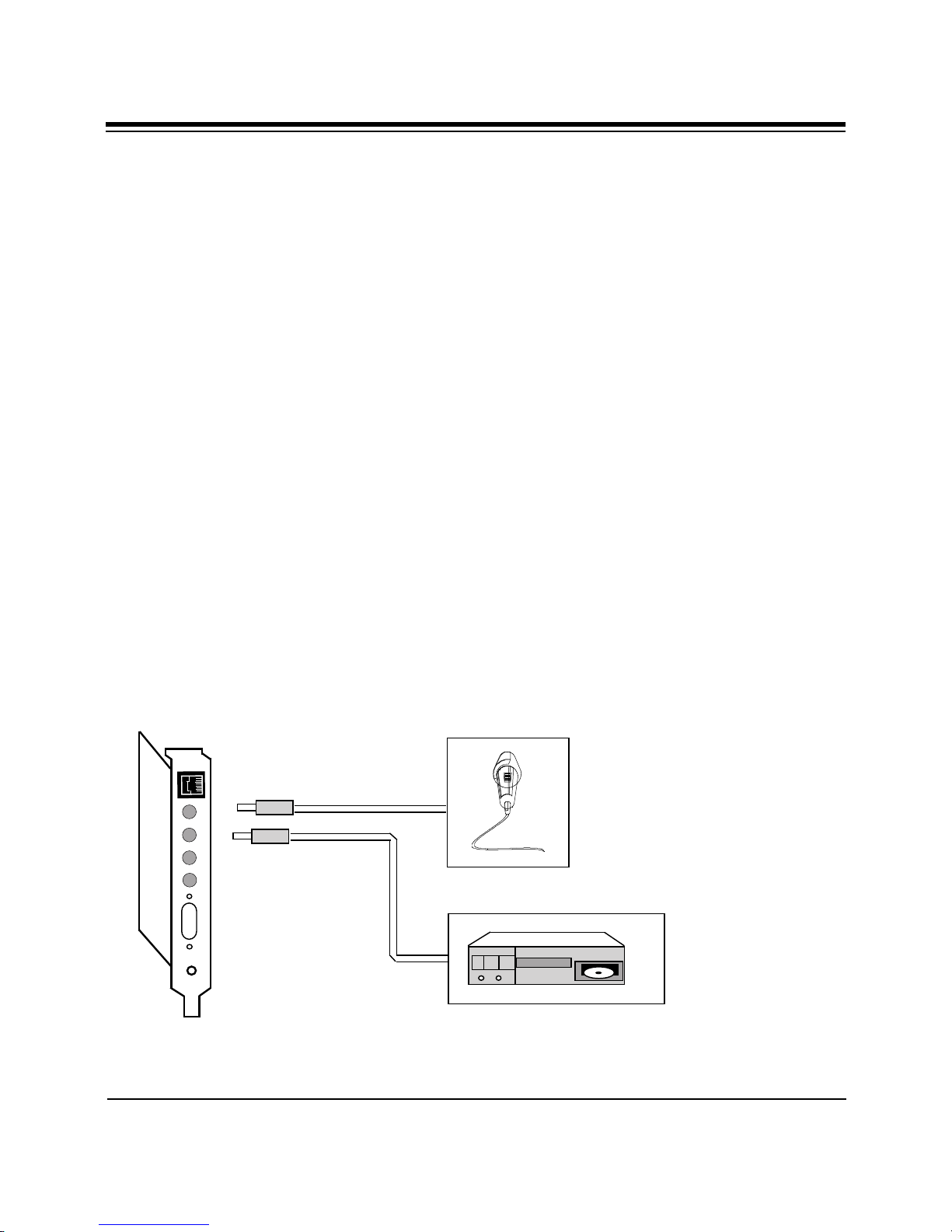
2.7 Attaching External Audio/
Game Devices
You can attach optional devices to the
remaining connectors as described
below. Note also the diagrams that
follow.
2.7.1 Attaching External Audio-in
Devices
15
1. If you are using a microphone, plug it
into the MIC connector. Use a dynamic
microphone with a resistance not
exceeding 600 ohms, or an Electret
(condenser) microphone. See Appendix
C for more information.
MIC
L-IN
L-OUT
SPK
.
.
.
.
.
.
.
.
.
.
.
.
.
.
.
2. If you are using a CD-player, hi-fi set,
radio set, synthesizer, or walkman,
plug it into the L-IN (LINE IN)
connector.
MICROPHONE
INPUT
(OPTIONAL)
INPUT DEVICE
(A CD-PLAYER
FOR EXAMPLE)
(OPTIONAL)
Installing Your SoundExpression
Page 16
16
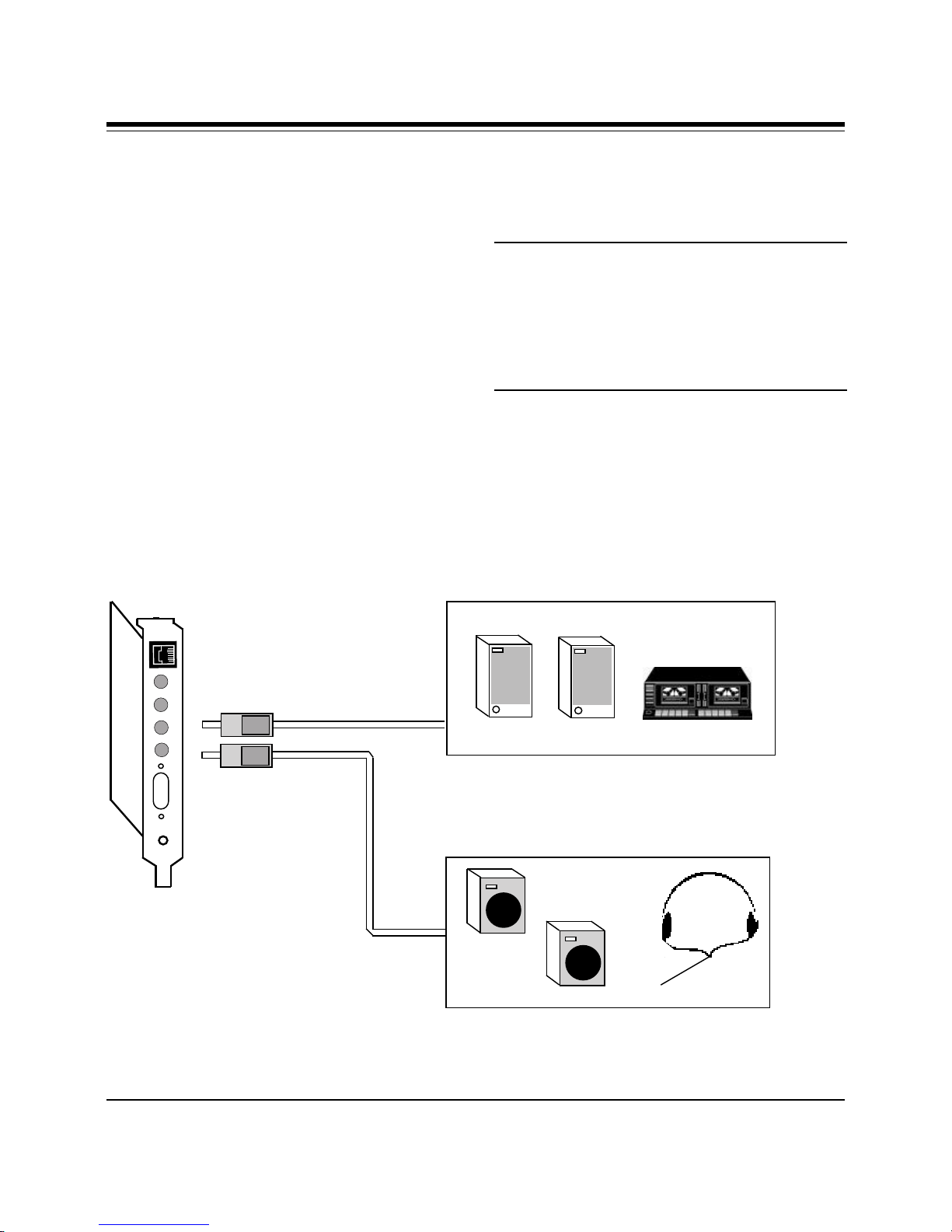
2.7.2 Attaching External Audio-out
Devices
1. If you are using an amplified device
such as stereo amplifiers, tape cassette
recorders, headphones, or amplified
speakers, plug it into the L-OUT (LINE
OUT) connector (8 ohms or greater
impedance; see Appendix C for more
information).
2. If you are using an unamplified device
such as speakers, plug it into the SPK
(SPEAKER OUTPUT) connector (8
ohms or greater impedance; see
Appendix C for more information).
MIC
L-IN
L-OUT
SPK
.
.
.
.
.
.
.
.
.
.
.
.
.
.
.
OUTPUT DEVICE (AMPLIFIED) SUCH AS STEREO
SPEAKERS OR STEREO TAPE RECORDER, FOR
EXAMPLE (OPTIONAL)
IMPORTANT: To avoid temporary or
permanent hearing loss or impairment
due to unexpected noise or static,
always hold your headphone away from
your ears and test the sound before
putting them on.
SoundExpression
OR
or
OUTPUT DEVICE (UNAMPLIFIED) SUCH AS STEREO
SPEAKERS OR HEADPHONES, FOR EXAMPLE (OPTIONAL)
Page 17
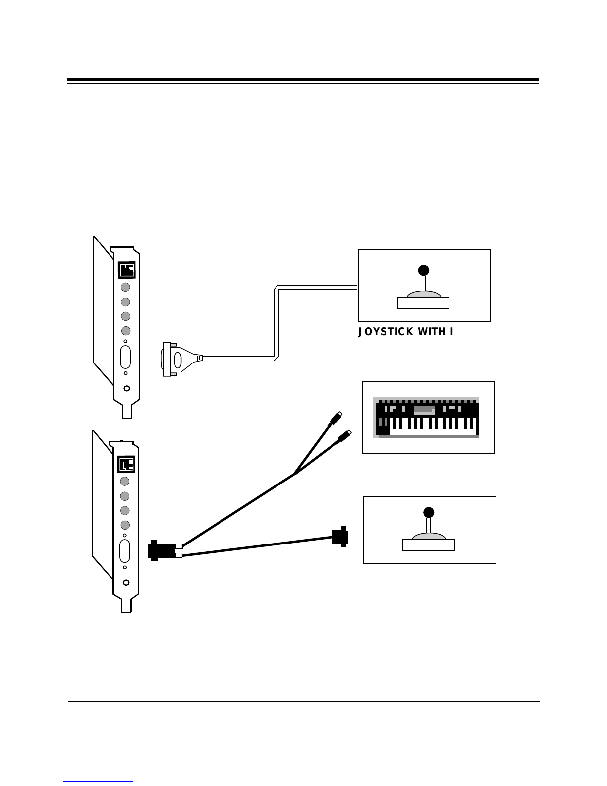
JOYSTICK WITH IBM PC
COMPATIBLE 15-PIN D-SUB
CONNECTOR (OPTIONAL)
IN
OUT
MIDI CABLE
.
.
.
.
.
.
.
.
.
.
.
.
.
.
.
MIC
L-OUT
L-IN
SPK
.
.
.
.
.
.
.
.
.
.
.
.
.
.
.
MIC
L-OUT
L-IN
SPK
JOYSTICK WITH IBM PC
COMPATIBLE 15-PIN D-SUB
CONNECTOR (OPTIONAL)
KEYBOARD SYNTHESIZER
(OPTIONAL)
Installation of internal and external components is complete. Windows 3.1 and DOS
users should turn to section 2.8 for Driver Installation. Windows 95 users should
turn to section 2.9.
Installing Your Sound Expression
2.7.3 Attaching a Joystick/MIDI
Device
1. If you are connecting a joystick only,
use a 15-pin cable with D-sub
connector. NOTE: You may also attach
two joysticks providing you have a
15-pin “Y” cable.
2. If you are connecting a MIDIcompatible keyboard synthesizer as
well, use a MIDI cable to make
connections as shown below.
Connecting external audio/game
devices is complete.
17
Page 18
18
2.8 Driver Installation for
Windows 3.1/DOS Users
3. To continue select one of the following
options:
1. If you are in Windows, exit to DOS.
2. Insert the driver diskette into your A:
or B: floppy drive and type
A:\INSTALL (or B:\INSTALL).
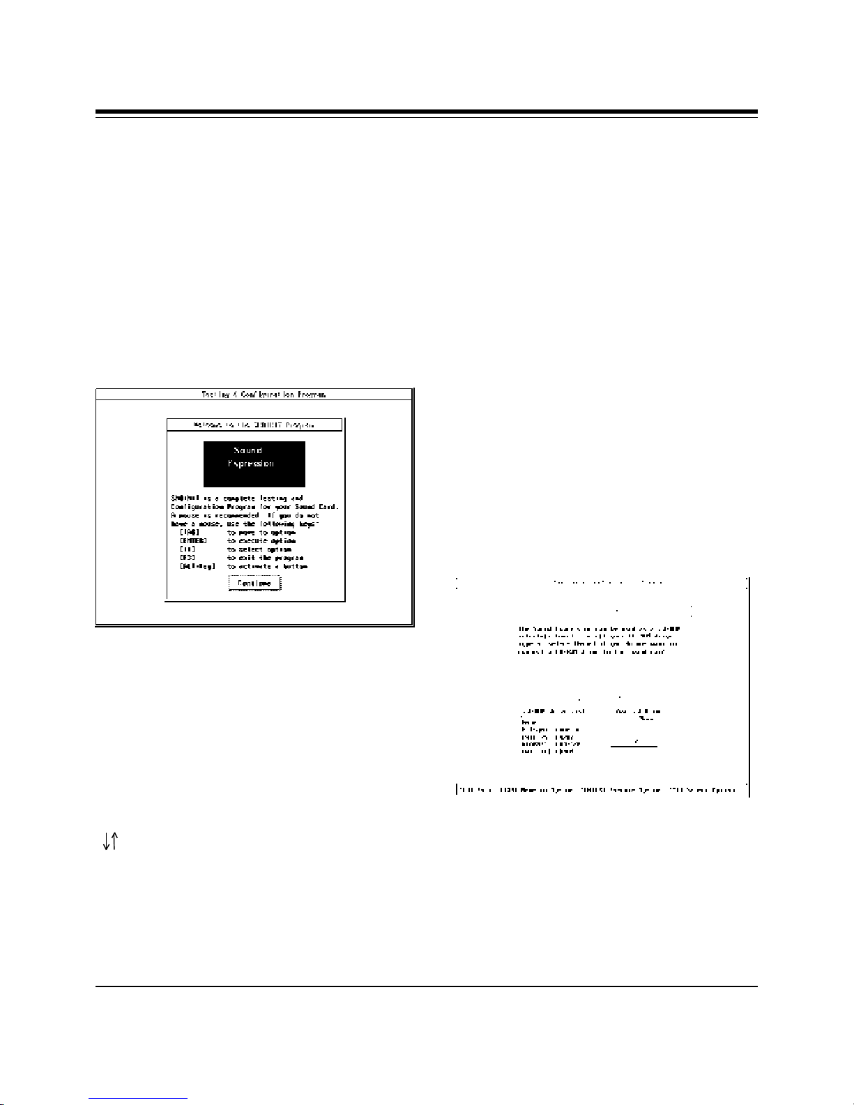
The following introductory screen is
displayed:
START INSTALLATION
VIEW README.TXT
EXIT
4. When you “Start Installation”, select a
destination directory (default is
C:\SOUNDEXP). Select OK.
5. If you have Windows, you will be
asked for your Windows directory. If
you do not have Windows installed on
your system, select “NONE”.
6. After confirming your selections, files
are copied to your hard disk. Then you
will be asked for a CD-ROM type.
Select “NONE” if you do not have a
CD-ROM.
If You Do Not Have a Mouse...
Use the following keys as described
below:
[TAB] Moves to Option.
[ENTER] Accepts Button.
Opens Combo Box for
selecting options.
Accepts options from combo
Box.
[ ] Selects Options within Combo
box.
[F3] Exits to DOS; all changes are
discarded.
[ALT + Activates a button on the
KEY] Configuration and Sound-Test
screen.
SoundExpression
7. Next you are presented with a
Configuration and Sound Test screen
(for details on options and functions,
see the instructions at the end of this
section if you need to change default
settings). When you are done, select
“ACCEPT”.
Page 19
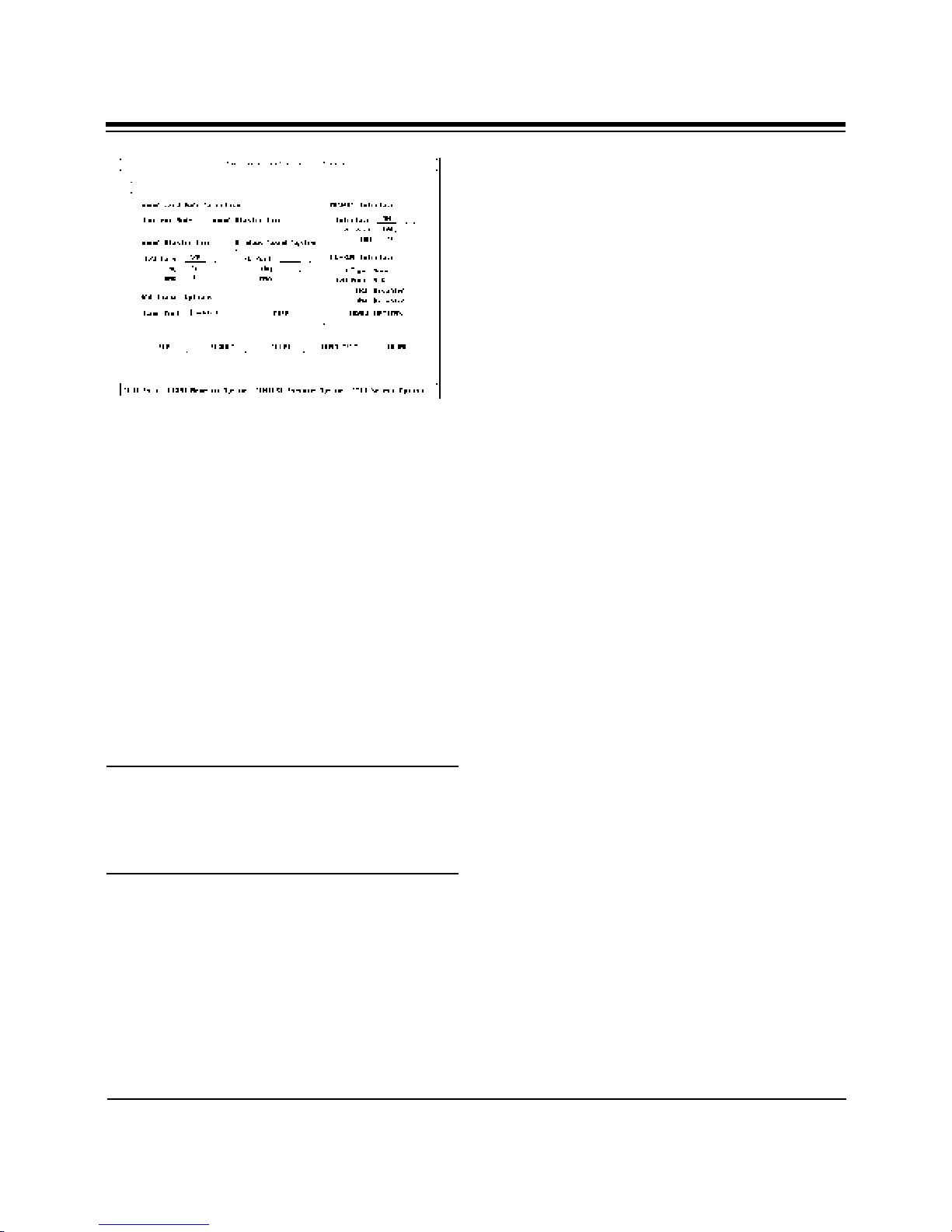
DEFAULT. Resets the current mode to
Sound Blaster Pro.
ACCEPT. Accepts the current chosen
options and exits. The program checks for
hardware conflicts. If a conflict exists,
a warning window is displayed. The
program updates the sound configuration
and system files: SOUND16.CFG,
CDROM.CFG, CONFIG.SYS,
AUTOEXEC.BAT, SYSTEM.INI, before
exiting to DOS.
19
8. You are then asked if you want to
update your CONFIG.SYS file. Select
“OK”.
9. Lastly, you will need to power down
your system, then restart. Driver
installation is complete for Windows
3.1/DOS users. If you need to
reconfigure the board, type SNDINIT
at the \SOUNDEXP directory to run
configuration. See the next section.
Running the Configuration and
Sound-Test Utility (SNDINIT)
(Windows 3.1/DOS Users only)
NOTE: If you have a Plug and Play
computer, use its Plug and Play
Configuration utility to change settings. You
will not be able to change resource
assignments using SNDINIT.
Button Function Descriptions
A button can be activated by either a
mouse, keyboard [ENTER] or ALT +
button’s hotkey. The following are the
BUTTON names and their function
descriptions:
HELP. Brings up a help page.
SOUND TEST. Brings up the Sound Test
Window. The Sound Test Window performs
the following with the chosen hardware
settings:
• 8-Bit Sound Test (Test SB Pro settings)
• 16-Bit Sound Test (Test WSS settings)
• FM Music Test
VOLUME. Brings up the Volume Control
Window. The Volume Control Window
allows you to adjust the following volume
settings:
•Master Volume
•Voice Volume
• FM Music Volume
• CD Audio Volume
CHANGE OPTIONS. Brings up the CDROM Configuration Window. The CD-ROM
Configuration Window allows you to
configure your CD-ROM drive for the
following:
• CD-ROM Drive Type
• MSCDEX selection
• I/O Address
• Interrupt
• DMA Channel
Installing Your SoundExpression
Page 20
20
Combo Box Functions and
Hardware Configuration
Descriptions
You can activate a combo box by mouse,
or keyboard [ENTER]. When activated, a
list box with options is opened for
selections.
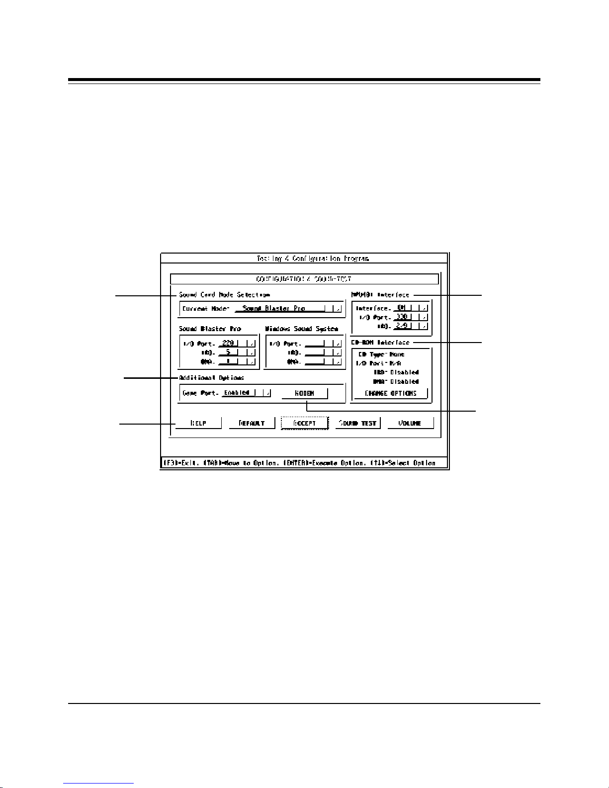
Sound Card Mode Selection
Current Mode. Your sound card can
operate in one of the following two
modes:
[Sound Blaster Pro] or
[Windows Sound System] Mode
Mode
Selection
Additional
Options
Button
Functions
The following describes each sound
card’s hardware section and available
options as highlighted above:
MPU
Interface
CD-ROM
Interface
Modem
Select [Sound Blaster Pro] mode to enable
your sound card to play Sound Blaster
compatible DOS games. (Default)
Selecting [Windows Sound System] mode
will switch your sound card into the
mode to play those DOS games or
utilities written for Microsoft WSS
compatible sound cards. The selected
mode becomes the current mode upon
exiting.
SoundExpression
Page 21

21
Sound Blaster Pro (for SB Pro Mode
Only; *=default)
I/O Port. SB Pro I/O Port selections:
*220, 240
IRQ SB Pro Interrupt Address
selections: *5, 7, 10
DMA SB Pro DMA Channel
selections: *1, 0, 3
Note: 8-bit Sound Test in the Sound Test
Window can be used to test Sound
Blaster Pro Mode regardless of the
Current Mode setting.
Windows Sound System (for WSS
Mode Only; *=default)
I/O Port WSS I/O Port selections:
*530, E80, F40, 604
IRQ WSS Interrupt Address
selections: *11, 7, 9, 10, 5
DMA WSS DMA Channel
selections: *0, 1, 3, 0/1, 1/0,
3/0
There are two modes for DMA selections:
Note: 16-bit Sound Test in the Sound
Test Window can be used to test
Windows Sound System Mode
regardless of the Current Mode setting.
MPU401 Interface
MPU401 is the industrial standard
interface for MIDI (Music) devices such
as keyboards and some Wave Table
Synthesizer devices. (*=default)
Interface. External MIDI enable or
disable selections: *ON, OFF.
I/O. Port. External MIDI I/O Port
selections: *330, 300, 320.
IRQ. External MIDI Interrupt Address
selections: *9, 5, 7.
CD-ROM Interface
Your sound card also could be used as a
CD-ROM interface card to connect to an
IDE-compatible CD-ROM drive.
[Single DMA]: Uses a single DMA
channel for DMA playback and capture.
[Dual DMA]: Allows to playback and
record at the same time. 0/1, 1/0, 3/0 are
the Dual DMA selections. The first one is
for Playback. The second is for recording.
CD Type. CD-ROM selected drive type.
*NONE or CD-ROM drive
types...
I/O Port. CD-ROM selected I/O port.
IRQ. CD-ROM selected Interrupt
Address.
Installing Your SoundExpression
Page 22
22
DMA. CD-ROM selected DMA
Channel.
CHANGE OPTIONS. Brings up CD-ROM
configuration menu.
Additional Options
Game Port. Game Port enable and disable
selections: *Enable, Disabled
MODEM
Change the following settings for the
modem or accept the defaults:
Interface: *ON, OFF
I/O Address: *2E8, 3E8, 2F8, 3F8
Interrupt: *3, 4, 5, 7, 9, 10, 11
Configuration is complete.
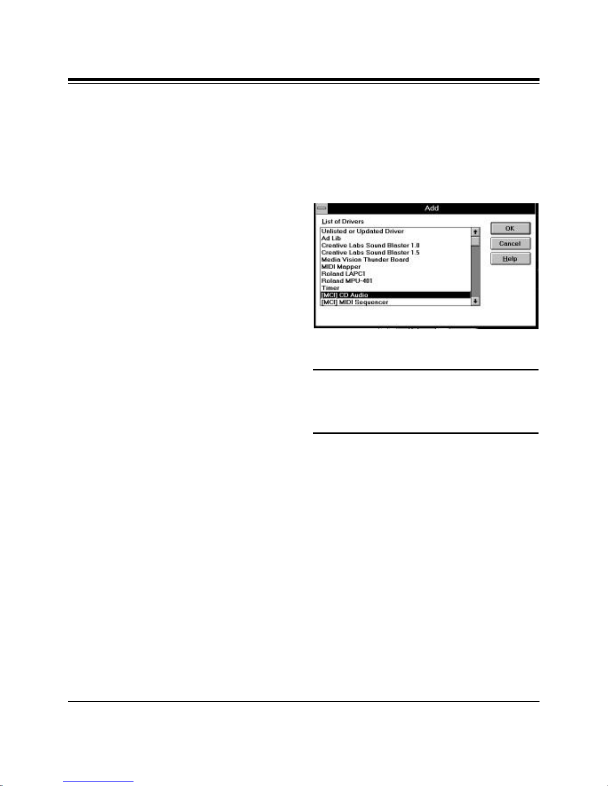
Highlight the “[MCI] CD Audio Driver”
and select OK. You may be asked for your
original Windows diskettes in order to
copy the driver.
NOTE: When you restart Windows, you
will be asked if you want to create a
Program Group for the Audio
Applications. Choose “Yes”.
Completing the Installation for
Windows 3.1 Users
After re-booting, ignore any error
messages that may be a result of an
unconfigured CD-ROM drive. Refer to
the information you noted at the CDROM screen if you need to re-configure
your CD-ROM drive.
At this time you will need to install the
MCI CD Audio driver in order to play
musical CDs through Windows. Select
Control Panel, then Drivers, then Add....
SoundExpression
Congratulations! Installation of the
SoundExpression is complete. Now you
may install your fax and audio
applications. Refer to Section Four for
troubleshooting information if you
require further assistance.
Page 23
23
2.9 Driver Installation for
Windows 95 Users
1. When the SoundExpression board is
physically installed, start Windows 95
as you normally would.
2. When Windows 95 detects new
hardware, it displays the “New
Hardware Found” dialog box. Here,
you are asked what (if any) driver files
are associated with the new hardware.
3. From the choices given, select “Driver
from disk provided by hardware
manufacturer”.
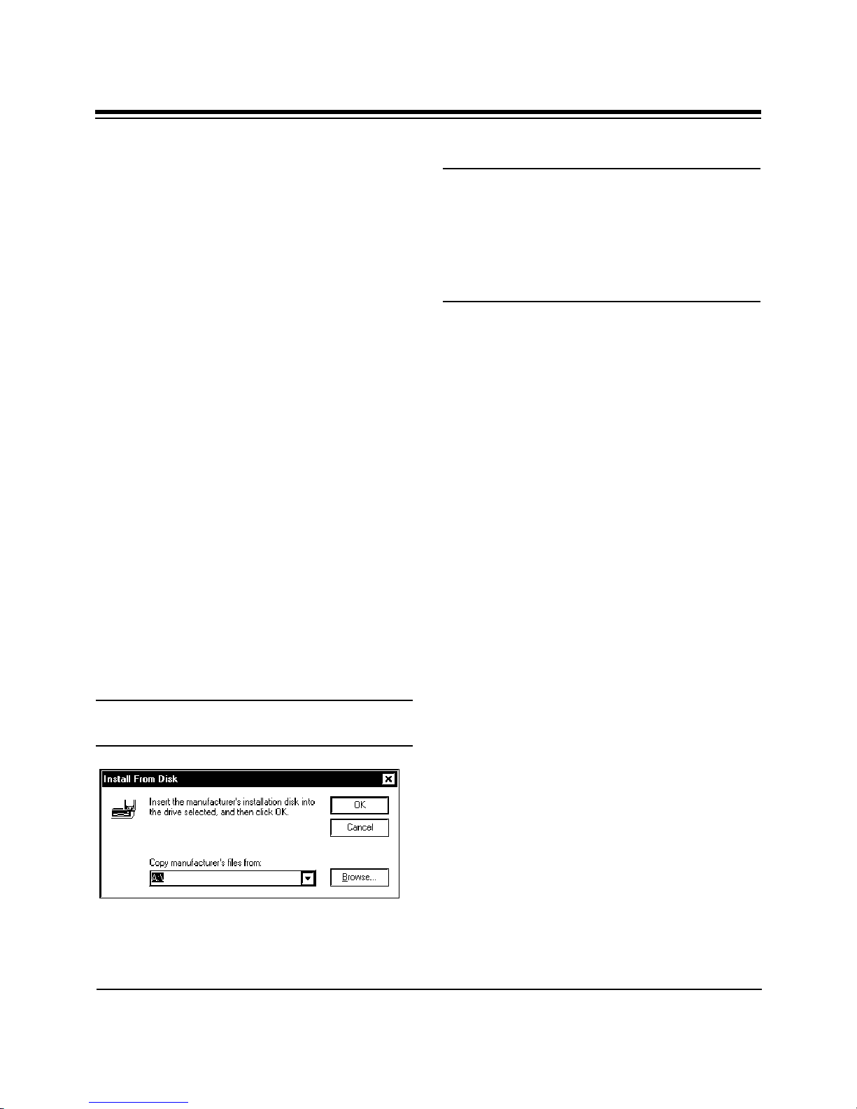
4. Windows 95 then displays the “Install
from Disk” dialog box. Here, you are
asked for the location of the driver
files. Insert the SoundExpression
driver diskette in your floppy drive.
Type A: (or B:) and select OK.
Windows 95 will now copy files from
the installation diskette.
NOTE: Windows 95 will detect a number of
devices on the SoundExpression board.
After each device is installed, you may be
prompted to restart Windows 95. It is not
necessary to restart Windows 95 until all
devices are detected and set up.
5. Windows 95 will detect the following
devices on the board. For each of these
devices as listed, select “Windows
Default Driver”.
• Game Port Joystick
• Standard IDE/ESDI Hard Disk
Controller
6. Windows 95 may prompt you to restart
your computer to finish setting up the
devices on the board. Select “NO” so
Windows 95 will continue installing
the devices present on the board. Some
steps may be repeated. Follow all onscreen instructions.
You may be asked for your original
Windows diskettes.
7. Windows 95 then displays the “Install
from Disk” dialog box (as shown in
step 4). Here, you are asked for the
location of the driver files. Insert the
appropriate driver diskette in your
floppy drive. Type A: (or B:) and select
OK. Windows 95 will now copy files
from the diskette.
Installing Your Sound Expression
Page 24
24
8. When all the new devices are installed,
Windows will finish loading. When
Windows 95 displays the “Start
Menu”, select “Start”, then “Shut
Down”, then “Restart the Computer”.
This will restart Windows 95 with the
newly installed drivers.
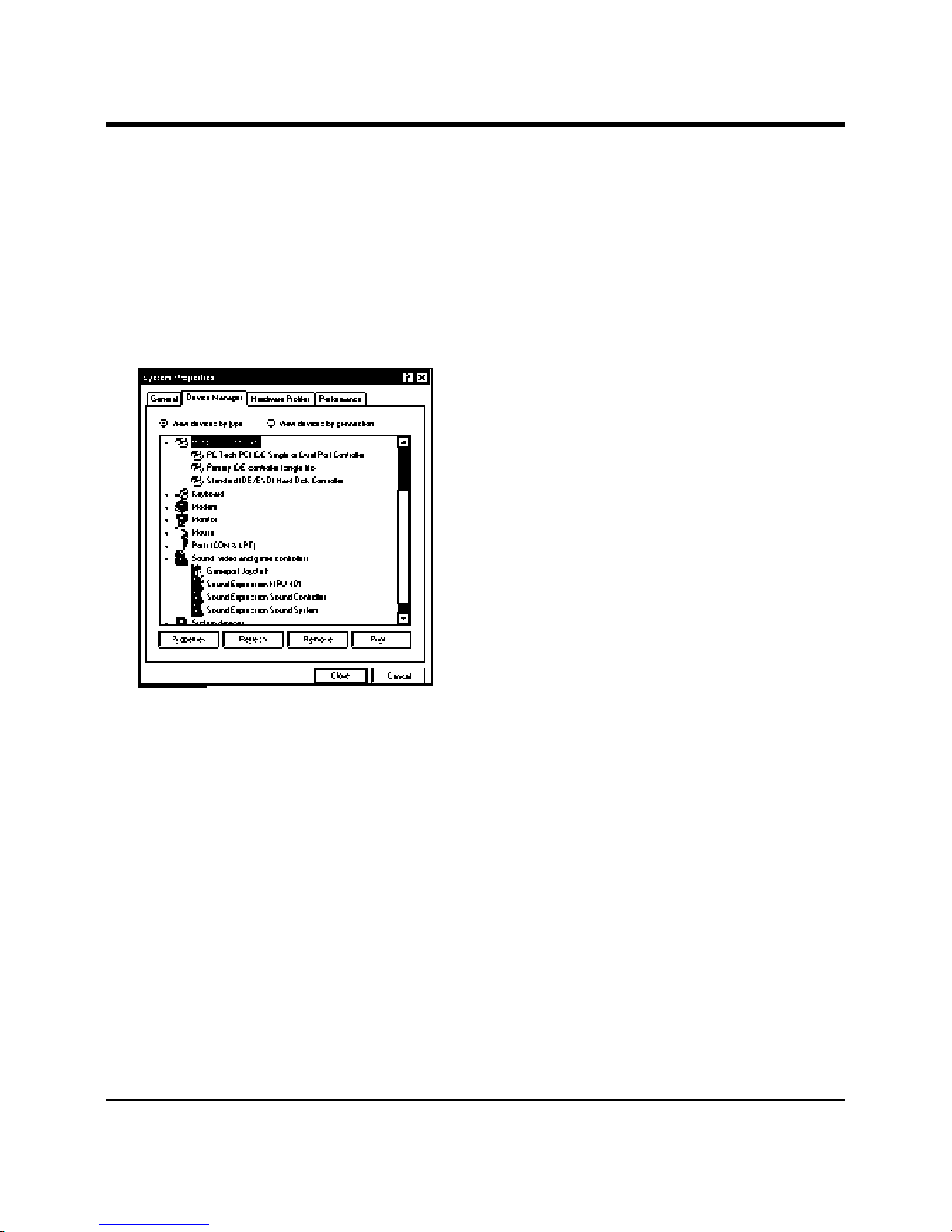
If you need to re-configure the board,
click on “Control Panel”, then “System”,
then “Device Manager”. The drivers are
under the section, “Sound, Video, and
Game Controllers”. See your Windows 95
documentation on changing properties of
devices using the Device Manager.
Congratulations! Driver installation is
complete for Windows 95 users.
Now you may install your fax and audio
applications. Refer to Section Four for
troubleshooting information if you
require further assistance.
SoundExpression
Page 25

Section Three: Modem
Functions and Features
3.1 Introduction
The SoundExpression offers the latest in
modem technology, featuring voice, fax,
and data communications. This versatile
modem allows you to establish a
structured set of messages, mailboxes,
and faxes. Now, you have an all-in-one
communications product that serves as a
modem, voicemail system, and fax
machine.
The SoundExpression also supports
business audio applications such as
digital answering machine, voice
annotation, and audio file play and
record.
Features:
Voice Capabilities
The SoundExpression features speaker
phone capability, auto-dial, auto-answer,
and an embedded voice modem ‘AT’
command set. The modem supports basic
answering machine functions through the
included voice and fax communications
software as well as full-duplex
speakerphone. You can also set up
multiple mailboxes.
The automated attendant feature allows
dial-in users to access various mailbox
features. When dialing in, you can check,
answer, and leave messages. You can also
25
retrieve faxes; enable/disable toll saver;
change personal mailbox greetings;
enable/disable pager notification; and
change fax forwarding and pager
notification numbers.
Fax Capabilities
The SoundExpression offers a wide range
of fax services It supports Group 3, class
1 and 2 fax send and receive operations.
It complies with ITU-T (formerly CCITT)
V.17 (14.4Kbps), V.29 (9600bps), V.27ter
(4800bps), and V.21 (300bps) channel 2
international fax standards.
Data Capabilities
The SoundExpression offers the widest
possible range of internationally accepted
standard modulation methods and
protocols. The modem is capable of up to
115,200Kbps (SE34SRS and SE34SVD) or
57.6Kbps (SE14SRS) data throughput with
data compression. It complies with ITUTSS standards V.34, V.FC (28.8Kbps),
V.32bis (14.4Kbps), V.32 (9600 bps),
V.22bis/V.22 (2400 bps), and V.21
(1200bps), as well as Bell 212A and 103.
The modem implements V.42 error
correction with LAP-M and MNP 2-4, as
well as data compression with V.42bis
and MNP-5.
Modem Functions and Features
Page 26

26
Ideal for Travelers
Voice features allow for remote call-in
with full services to answer, route, delete,
or forward messages. For example, while
you are traveling, faxes are stored on
your hard drive. When you call in to
review a voice message, a fax forwarding
function allows received faxes to be
forwarded to another fax number at any
location.
3.2 Testing the Connection
1. Check that you have made all
connections as instructed in section 2.6
(Connecting for Modem Use). Power
on the computer.
4. Start your communications software
and enter terminal mode. If you are not
in terminal mode, AT commands typed
in at the DOS prompt will result in a
“Bad Command or File Name”
message.
5. Type in ATZ followed by ENTER and
the modem will respond with OK after
a few seconds. If the modem does not
respond OK, refer to Troubleshooting
(Section Four).
6. Type ATH1 followed by ENTER and
you should hear a dial tone from the
external speakers attached to the
SoundExpression. To adjust speaker
volume, refer to your communications
software, or use the ATL3 command.
2. Check for a dial tone on a phone set if
one is connected. If a dial tone is heard,
continue. If you do not hear a dial tone,
check the connections you made in the
previous subsection, or refer to
Troubleshooting (Section Four).
3. Install and configure your
communications software (see
companion software manual) and place
it in command mode. Refer to the
communication software manual for
additional information.
SoundExpression
7. Type ATH followed by ENTER to put
the modem “on-hook”. This confirms
that the modem has been successfully
installed into the computer.
8. Your modem is now ready for use.
Proceed now to your communications
software and documentation.
Page 27

27
Section Four:
Troubleshooting
Commonly Encountered
Problems and Solutions
SYMPTOM
Your computer does not boot up after
installing the board.
POSSIBLE REMEDY
The sound board may not have been
inserted completely into the 16-bit slot.
Refer to Section Two: Installing Your
SoundExpression to install the sound
board properly.
SYMPTOM
The computer hangs, reboots itself, or
issues a parity error after the board is
installed.
POSSIBLE REMEDY
There might be a hardware conflict
between the sound card and the other
device. Run SNDINIT (page 19-22) to
find out which hardware setting is
conflicting
SYMPTOM
Your system hangs when you enter or
exit Windows.
POSSIBLE REMEDY
a) If you installed another sound card in
your system before, make sure you have
removed all its drivers in Windows
including any virtual device driver.
b) There might be conflicts with another
device in your system. Run SNDINIT
(page 19-22).
POSSIBLE REMEDY
There is a hardware conflict between the
sound card and other interface cards in
your system. Power down and remove all
other cards except the SoundExpression,
your video card, and the hard drive
controller. Reboot again.
SYMPTOM
A device in your computer does not work
or does not work properly after the board
is installed.
SYMPTOM
There is no sound output in games.
POSSIBLE REMEDY
a) Check that the speakers are connected
properly to the L-OUT (amplified
speakers) connector or SPK (unamplified
speakers) on the sound card. If your
speakers use batteries, make sure that
they have the batteries they need.
b) Refer to the documentation for the
application or operating system you are
Troubleshooting
Page 28

28
using to determine how to adjust the
volume.
c) Make sure that the sound board is
inserted properly into the computer.
d) If your games are Sound Blaster
compatible, make sure the card is in
Sound Blaster mode. You can find out
what mode the sound card is in by
running SNDINIT (page 19-22).
e) There might be a DMA conflict
between the sound card and other
interface cards in your computer. Make
sure the DMA channel your sound card is
using is not being used by another device
in your system.
f) Some games need EMM to play
digitized voice. Please refer to the
documentation that comes with your
game.
g) Check the address, DMA, and IRQ
settings required by the game.
b) Make sure amplified speakers are
attached to L-OUT (LINE OUT) jack;
make sure non-amplified speakers are
attached to SPK (SPEAKER) jack.
c) Interference from another interface
card in your computer. Try to install the
sound card into a different slot.
SYMPTOM
There is no music or digitized voice or
there is only music in some applications.
POSSIBLE REMEDY
a) Some applications need extended or
expanded memory to run properly. Use a
memory manager to set up the required
memory in your system. Refer to the
application’s user guide on what is
required.
b) You do not have enough memory to
run the game. Remove non-essential
device drivers.
SYMPTOM
The sound is distorted during sound test
or during normal usage.
POSSIBLE REMEDY
a) Your speakers might be defective or the
quality of the speakers is poor. Make sure
you have a good pair of speakers.
SoundExpression
c) Make sure you have a set blaster= line
in your autoexec.bat file (example:
set blaster=a220 i5 d1.
SYMPTOM
Your CD-ROM drive doesn’t play music
CDs or you receive the message:
“CD-ROM Driver Not Detected”
Page 29

POSSIBLE REMEDY
a) Make sure the CD-ROM audio cable is
connected to the CD audio-in connector
on the Sound card.
29
b) There is a conflict between the game
port on the sound card and the game port
in your system. Remove the additional
joystick from your system.
b) Install the MCI CD Audio driver in
Windows. Some applications need this
driver to play music CDs. The driver is
provided by Windows. Simply select
Control Panel in the Windows Program
Manager. Then select Drivers and Add a
Driver. Select “MCI CD Audio Driver”.
This will require your Windows diskettes.
c) Check the speakers connection. If your
speakers use batteries, make sure they
have the power they need.
d) Check the documentation that comes
with your CD-ROM drive on setting up
your CD-ROM for playing Audio CDs.
Make sure the volume control is turned
up in the software.
SYMPTOM
Your joystick does not work after
installing the board.
SYMPTOM
The joystick is not working properly in
some programs.
POSSIBLE REMEDY
The CPU speed of your computer might
be too fast. You might want to reduce the
speed. Refer to your computer’s manual
for instructions on setting up your
computer’s operating speed.
SYMPTOM
You cannot record any sound using a
microphone.
POSSIBLE REMEDY
a) If your microphone has an On/Off
switch, make sure the switch is turned
on.
b) Make sure you plug the microphone
into the mic-in connector.
POSSIBLE REMEDY
a) The joystick port on the
SoundExpression may be disabled. Run
the SNDINIT utility (pages 19-22) to
enable the game port.
c) The microphone must be a mono
Electret (condenser), or dynamic type,
with a resistance of no greater than 600
ohms.
Troubleshooting
Page 30

30
SYMPTOM
There is no sound or the sound is
distorted when you are running
Windows Sound System applications.
POSSIBLE REMEDY
You need the Microsoft Audio
Compression Manager to play
compressed files in Windows Sound
System applications. Make sure you have
the following line in the [drivers] section
of your system.ini file:
wavemapper=msacm.drv
SYMPTOM
Your speaker phone does not work
POSSIBLE REMEDY
Refer to the documentation for your
communications software.
SoundExpression
Page 31

Modem Problems
This section lists common problems that
may be encountered with modem usage
and their possible solutions.
SYMPTOM
No dial tone.
31
• Make sure your communications
application is set up for the
SoundExpression, or a generic 14.4Kbps
modem with AT&F as its init string.
SYMPTOM
No response when you type in AT
commands
POSSIBLE REMEDY
• Verify that you have cables plugged in
correctly as instructed in 2.6 and.
• Connect a telephone set directly to the
wall jack and check for a dial tone. If
no dial tone is heard, the telephone line
is not working. Contact the telephone
company.
SYMPTOM
Modem will not connect to another
modem.
POSSIBLE REMEDY
• Check the connections between the
modem and the computer, and the
modem and the telephone line.
• Make sure the telephone jack is
operational as described above.
POSSIBLE REMEDY
• There may be a conflicting port
address. Re-configure the modem’s
COM port address
• Verify that the communication software
is set to the same communications port
that your modem is set to (e.g., COM1,
COM2). Check IRQ settings in your
software and on the modem.
• Try typing AT&F to reset the modem to
its factory defaults.
• Check the modem settings by running
SNDINIT (pages 19-22). Make sure the
modem interface is set to ON.
SYMPTOM
AT commands not visible.
POSSIBLE REMEDY
• The telephone line may be in use at a
different extension.
• Make sure the echo command is set to
ON. Change to echo with the ATE
command.
Troubleshooting
Page 32

32
SYMPTOM
After data connection is established, data
is displayed as garbled characters.
POSSIBLE REMEDY
• Make sure the local (yours) and remote
modem configurations are compatible.
• Verify that both modems are operating
with the same settings, speed, data,
parity, and stop bits.
• The software may not be set for correct
terminal emulation. Configure software
to correct type. ANSI terminal
emulation is most commonly used.
• Power down your system and re-run
your communications software. Check
software settings.
• Exit the communications program and
restart it.
• If you have an answering machine, it
may be answering before the modem
can. Turn the answering machine off, or,
use the software to set auto-answer to
respond in fewer rings than the
answering machine.
SYMPTOM
Modem disconnects while on-line.
POSSIBLE REMEDY
• Check for any loose connections.
• Re-try the connection by dialing the
number several times. You may be
experiencing line interference.
• An incoming call may have broken the
connection if a call-waiting feature was
enabled. Disable call-waiting and try
again.
SYMPTOM
The modem does not answer an incoming
call.
POSSIBLE REMEDY
• You may not have enabled auto-answer.
Use your software to enable this
function. Type ATS0=1 at the command
mode screen of your data
communications application.
SoundExpression
SYMPTOM
Speaker fails to work.
POSSIBLE REMEDY
• Make sure attached speaker is working
and conforms to necessary
specifications. See Appendix C.
Page 33

33
Appendix A: Technical
Specifications
The SoundExpression is an integrated
sound controller compatible with Sound
Blaster, Ad Lib, and Microsoft Windows
Sound System. It is also a 28.8Kbps
(SE34SRS, SE34SVD) and 14.4Kbps
(SE14SRS) fax/data/voice modem.
n Plug and Play.
n 8 or 16-bit sound data: Sound Blaster
and Windows 8/16-bit audio up to
44.1Khz stereo
n SRS® Sound-compatible.
n DSVD-compatible.
n Software programmable CD ROM
interface for SONY, Mitsumi, and
Panasonic IDE CD ROM
n Software enable/disable of the game
port
n Supports 7 DMA and 6 IRQs
n 24mA drivers for direct AT-bus
interface
n 16mA drivers for direct CD-ROM
interface
n Full-Duplex Speaker phone
n Fax/data/voice modem with 16C550
UART
n DigiTalk® Standard
n Sample rates up to 48KHz stereo
n Integrated MIDI UART with 64-byte
FIFO
n Built-in Sound Blaster-compatible
digital audio processor
n Interface for Wave Table Synthesis
n Software Programmable AT interface
for I/O address, IRQ, and DMA
Channel
Modem Data Rate: 28.8K (SE34SRS
and SE34DVD only), 14.4K, 12K, 9600,
7200, 4800, 2400, 1200, or 300bps
Fax Data Rate:14.4K, 12K, 9600, 7200,
4800, 2400bps
Audio Data Rate: 4800 samples/sec.
Technical Specifications
Page 34

34
Compatibility:
Modem Modulation Protocols
ITU-T: ITU-T V.34 (SE34SRS and
SE34SVD only), V.32bis (14.4Kbps), V.32
(9600bps),V.22bis (2400bps), V.22
(1200bps)
Bell: Bell 212A (1200bps), Bell 103
(300bps)
Fax Modulation Protocols
V.17 (14.4Kbps) transmit and receive
V.29 (9600/7200bps) transmit
V.27 ter (4800/2400bps) transmit and
receive
V.21 channel 2 (300bps) transmit and
receive
EIA-578 Service Class 1 commands
Physical and Electrical Characteristics
n Dimensions: 13.4" x 4.2"
n Power:
+5V, 1.2 watts (maximum)
+/-12V, 0.5 watts (maximum); (from
host computer power supply)
n Operating Temperature
Requirements
Dry Bulb Temperature:
10-40o C (50-104o F)
Relative Humidity: 8-80%
Storage: 1-60o C (33.8-140o F)
V.42/MNP2-4 and V.42bis/MNP5 support
Diagnostics:
• Local/remote digital and analog
loopback.
• Automatic power-on self-test.
SoundExpression
Page 35

Appendix B: Configuration
Settings
Sound Blaster IDE CD (only)
Addresses: 220, 240 Address: 170
IRQ: 5, 7, 10 IRQ: 15
DMA: 0, 1, 3
Windows Sound System MODEM Addresses
Addresses: 530, E80, F40, 604 COM1, 2, 3, 4
IRQ: 7, 9, 10, 11 IRQ3, 4, 5, 7, 9, 10, 11
DMA: 0, 1, 3
MPU-401 Interface
Addresses: 300, 320, 330
IRQ: 2/9, 5, 7
Default Configuration
The SoundExpression supports both Sound
Blaster as well as Windows Sound System
applications. After drivers are installed and
configured, the card is in Sound Blaster
mode when in DOS. It switches to
Windows Sound System mode when you
start Windows. The default configuration
for the board is as follows:
Mode: Sound Blaster
Interrupt: IRQ5
DMA Channel: DMA1
I/O Port Address: 220h
CD-ROM interface: None
35
The IRQ, DMA channel, and I/O port
address for the sound portion of the
SoundExpression are all softwareselectable. The type of CD-ROM and
modem interface, I/O port address, IRQ,
and DMA channel are softwareconfigurable as well.
IMPORTANT NOTE: The IRQ chosen
for the modem must be different than
the IRQs used for sound functions and
the CD-ROM interface. The Sound
Blaster settings for the SoundExpression
(DOS-based) may be different from the
Windows Sound System settings
(Windows-based).
Mode: Modem
Interrupt: IRQ3
DMA Channel: NA
I/O Port Address: 2F8h (COM2)
CD-ROM interface: IDE
Configuration Settings
Page 36

36
Appendix C: Microphone
and Speaker Requirements
The SoundExpression is equipped with
microphone (MIC) and speaker jacks
(SPK) for use with headset, speakers, and
microphone. The microphone can be used
to record outbound messages as well as
sound files. These messages can also be
recorded with a telephone attached to the
modem. However, a microphone is
recommended for better quality
recordings. You may use a combination
headphone and microphone or a separate
microphone and speaker(s).
Speaker Requirements
You can attach the SoundExpression to a
high-quality external speaker or the
earpiece of a handset or headset. The
external speaker must have an impedance
rating of 8 ohms or more.
Microphone Requirements
The microphone element should be of the
electret type also known (incorrectly) as a
condenser type. The microphone in most
telephone handsets and headsets are of
this type. The SoundExpression was
designed for a microphone sensitivity of 64 dBspl. Other microphone sensitivities
work equally well, with only a subjective
difference in loudness. Carbon
microphone elements will also work, but
don’t offer the quality of the electret.
Another common microphone element is
the dynamic type which will work with
the SoundExpression. Its sensitivity is
much lower, and its frequency response is
not as suitable for this purpose.
SoundExpression
Page 37
Appendix D: W ave Table
○ ○
○ ○
○ ○
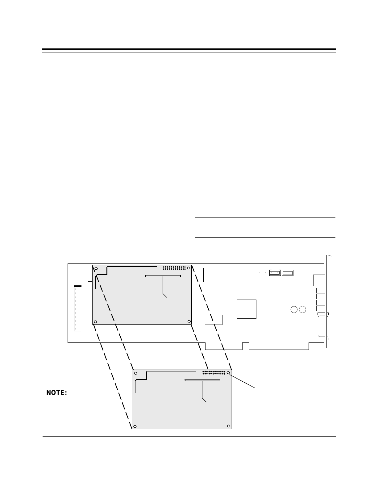
NOTE: Wave Table
cards vary in type
and size and may
not resemble the
one suggested here.
26-pin connector;
attach to wave table
connector on the
SoundExpression
3. Select MPU-401 in the Midimapper
dialog box.
Windows 95 Users
1. Start Windows 95.
2. Select Control Panel, then the MIDI
tab.
3. Next, select “MPU-401 Compatible”.
NOTE: To use internal FM synthesis,
select “...FM Synthesis” at the MIDI tab.
Card Installation
37
The SoundExpression will support a
Wave Blaster
tm
compatible wave table
card. The Wave Table card contains sound
samples of actual instruments. When
MIDI music is played using the wave
table card, the music will sound like real
instruments.
Windows 3.1 Users
To set up the Wave Table Card:
1. Start Windows as you normally would.
2. Select the Midimapper icon in the
Windows Control Panel.
Wave Table Card Installation
Page 38

38
Appendix E: A Note on the
MIDI Interface
MIDI (Musical Instrument Digital
Interface) is a standard for composing
and playing music using electronic
instruments and computers.
The MIDI interface transmits (MIDI-out)
and receives (MIDI-in) MIDI commands
serially at 32.5K baud. Multiple
instruments can be connected in a daisychain fashion to the MIDI interface.
MIDI commands are sent from a MIDI
sequencer (i.e., the computer) to the
attached instruments. Several
instruments can play simultaneously. The
result is similar to a complete band
playing a song.
MIDI songs consist of commands, not
actual digital sounds. Consequently, file
size is greatly reduced when compared,
for example, to a Windows .WAV file.
The SoundExpression can play MIDI
songs in three different ways:
1. Through an instrument attached to the
joystick/MIDI port.
When playing MIDI songs through the
MIDI port or wave table card, the
Windows MIDI mapper must be
configured for MPU-401 (1-16).
When playing MIDI songs through the
OPL3 FM synthesizer, the Windows MIDI
mapper must be configured for:
SoundExpression FM (1-10), or
SoundExpression FM (13-16), or
SoundExpression FM (1-16).
NOTE: Most MIDI files will play
correctly using the FM (1-10) setting.
This setting uses MIDI channels 1-10.
Some MIDI files may use channels 13-
16. In this case, the song or tune may not
play correctly. If this is the case, select
FM (13-16). The FM (1-16) setting allows
you to play MIDI files that use either
channels 1-10 or 13-16.
NOTE: Some MIDI files contain two
images of the song (dual-authored files).
In this case, the music on channels 1-10
is duplicated on channels 13-16. This
type of MIDI file will not sound
correctly. So, you should select FM (1-10)
instead.
2. Through an attached Wave Blaster
compatible wave table card (see
Appendix D).
3. Through the on-board OPL3 FM
synthesizer.
SoundExpression
tm
References
Microsoft Windows Multimedia Authoring and Tools
Guide
Microsoft Press
©1991 Microsoft Corporation
ISBN 1-55615-391-0
How MIDI Works
by Dan Walker
©1991 Peter L. Alexander Publishing, Inc.
Page 39
Appendix F: A Note on
Digital Sound
39
Traditionally, sound has been recorded in
analog format. Magnetic tape is an
example of the media used by analog
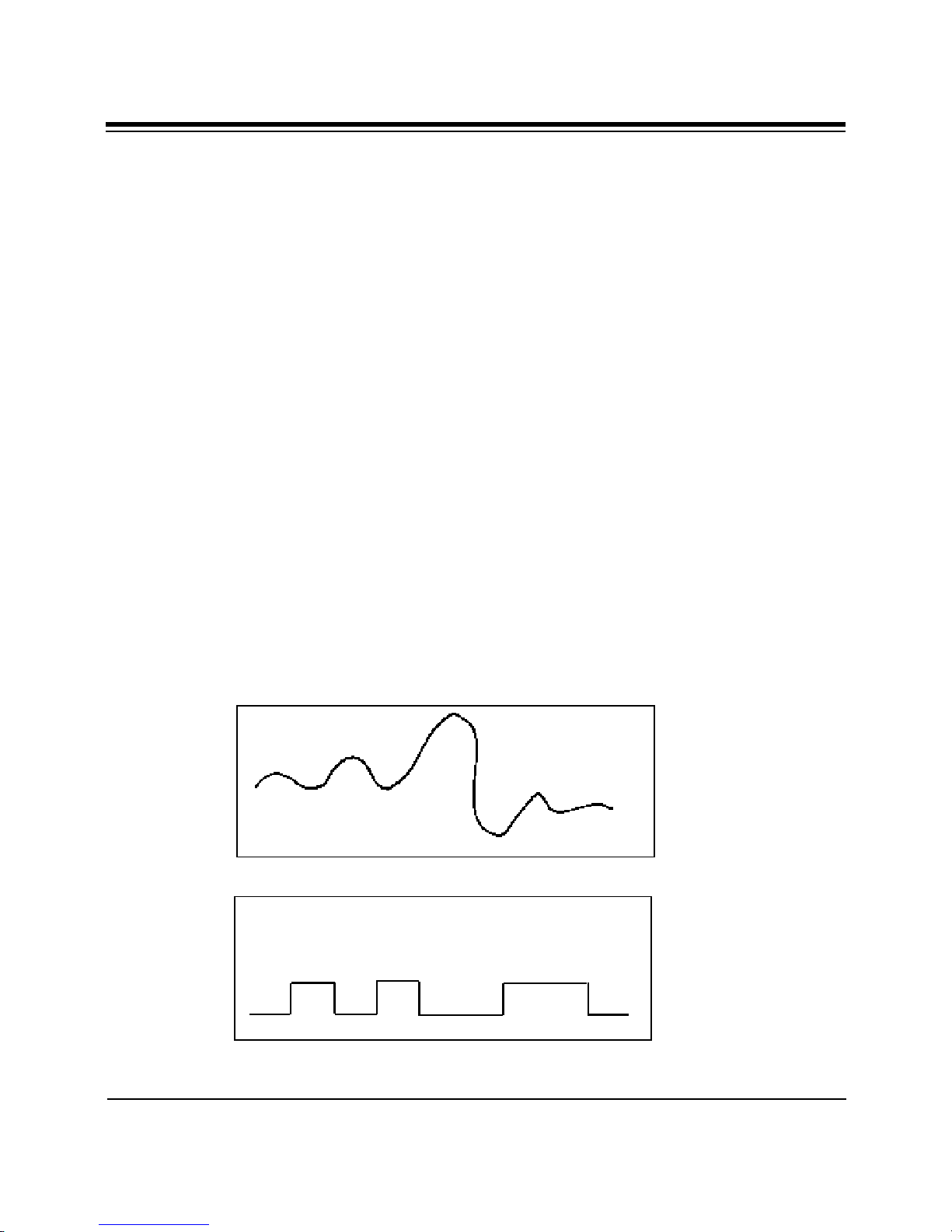
recording. Analog audio uses electrical
signals to create a single model of a given
sound or “waveform” as shown below:
Digital sound applies computer-based
technology to the recording, handling,
and regeneration of sound. A digital
waveform reduces the sound to a
sequence of binary numbers. Digital
audio systems sample the waveform and
extrapolate the complete sound from the
sample. When a digital recording is
played, the numeric data is transformed
back to its original acoustic waveform.
Tradeoffs
While the quality of a digital sound
recording is subject to almost no
degradation (unlike an analog recording),
digital sound storage requirements are
quite high in terms of computer hard disk
space.
Amplitude
0
Amplitude
Analog Waveform
Time interval
Digital Waveform
1
100 1
0
1
0
Time interval
A Note on Digital Sound
Page 40

40
Appendix G: A Note on
Windows Sound System
Windows Sound System provides 16-bit
44.1 KHz stereo record and play back
with OPL3 FM synthesis for DOS game
support in a DOS window. Settings for
Windows Sound System may be chosen
when selecting Driver Setup in the
Windows Control Panel. These settings
are as follows:
DUPLEX.
Half-duplex allows for either playing or
recording.
Full duplex allows simultaneous playing
and recording at the same sample rate.
Enhanced is the same as full duplex, but
simultaneous playing and recording may
occur at different sampling rates.
The default is full-duplex.
I/O Address. The default is 530h.
DMA Channel. The default is 1 for Play
and 0 for Capture. NOTE: you may use
the same DMA as your Sound Blaster.
DMA Channel is not active in Windows.
IRQ. IRQ10 is the best choice. If you
select IRQ9 or IRQ11, DOS-based games
will not be supported in a DOS window.
SoundExpression
Page 41

41
Appendix H: Compliance
Information
FCC Statement:
This device complies with part 15 of the FCC
rules. Operation is subject to the following
two conditions:
(1) This device may not cause harmful
interference.
(2) This device must accept any interference
received including interference that may
cause undesired operation.
THIS UNIT COMPLIES WITH FCC PART
68 AS OF DATE OF MANUFACTURE.
This equipment has been tested and found to
comply with the limits for a Class B digital
device, pursuant to Part 15 of FCC rules.
These limits are designed to provide
reasonable protection against harmful
interference in a residential installation. This
equipment generates, uses, and can radiate
radio frequency energy and, if not installed in
accordance with the instructions, may cause
harmful interference to radio
communications. However, there is no
guarantee that interference will not occur in a
particular installation. If this equipment does
cause harmful interference to radio or
television reception, which can be determined
by turning the equipment off and on, the user
is encouraged to try to correct the interference
by one or more of the following measures:
• Re-orient or relocate the receiving antennae.
• Increase the separation between the
equipment and the receiver.
• Connect the equipment into an outlet on a
circuit different from that to which the
receiver is connected.
• Consult the dealer or an experienced radio/
TV technician for help.
Note: This unit was tested with shielded
cables on the peripheral devices. Shielded
cables must be used with the unit to insure
compliance.
Note: The manufacturer is not responsible for
any radio or TV interference caused by
unauthorized modifications to this
equipment. Such modifications could void
the user’s authority to operate the equipment.
Notification to the Telephone
Company
Notification to the telephone company is no
longer required prior to connecting the registered
equipment but upon request from the telephone
company the user shall tell the telephone
company which line the equipment is connected
to as well as the registration number and the
ringer equivalence of the registered protective
circuitry. In most, but not all areas, the sum of all
RENs should be 5.0 or less. The FCC Registration
number and Ringer Equivalence number are
printed on the main chip in the center of the
internal modem board.
Malfunction of the Equipment
In the event that the modem should fail to
operate properly, the customer shall disconnect
the equipment from the telephone line to
determine if it is the customer’s equipment
which is not working properly, or if the problem
is with the modem, the user shall discontinue use
until it is repaired. In the event service is needed
the user should contact the vendor from whom
you purchased the modem.
Telephone Connection
Requirements
Except for telephone company-provided ringers,
all connections to the telephone network shall be
made through standard plugs and standard
telephone company-provided jacks, or
equivalent, in such a manner as to allow for easy
and immediate disconnection of the terminal
equipment. Standard jacks shall also be arranged
that, if the plug connected thereto is withdrawn,
Compliance Information
Page 42

42
no interference to the operation of the equipment
at the customer’s premises which remains
connected to the telephone network, shall occur
by reason of such withdrawal.
Incidence of Harm
Should terminal equipment or protective circuitry
cause harm to the telephone network, the
telephone company shall, where practical, notify
the customer that temporary discontinuance of
service may be required; however, where prior
notices are not practical, the telephone company
may temporarily discontinue service if such
action is deemed reasonable in the circumstances.
In the case of such temporary discontinuance, the
telephone company shall promptly notify
customers and will be given the right to bring a
complaint to the FCC if they feel the
disconnection is not warranted.
Changes in Telephone Company
Equipment or Facilities
The telephone company may make changes
in its communications facilities, equipment,
operations, or procedures, where such action
is reasonably required and proper in its
business. Should any such changes render the
customer’s terminal equipment incompatible
with the telephone company facilities, the
customer shall be given adequate notice to
make modifications to maintain
uninterrupted service.
General
The FCC prohibits customer-provided
terminal equipment be connected to party
lines or to be used in conjunction with coin
telephone service.
DOC Compliance Statement
(Canada)
The Canadian Department of Communications label
identifies certified equipment. This certification
means that the equipment meets certain
telecommunications network protective operational
and safety requirements. The Department does not
guarantee the equipment will operate to the user’s
satisfaction.
Before installing this equipment, users should
ensure that it is permissible to be connected to the
facilities of the local telecommunications company.
The equipment must also be installed using an
acceptable method of connection. In some cases, the
company’s inside wiring associated with a single
line individual service may be extended by means of
a certified connector assembly (telephone extension
cord). The customer should be aware that
compliance with the above conditions may not
prevent degradation of service in some situations.
Repairs to certified equipment should be made by
an authorized Canadian maintenance facility
designated by the supplier. Any repairs or
alterations made by the user to this equipment, or
equipment malfunction, may give the
telecommunications company cause to request the
user to disconnect the equipment.
Users should ensure, for their own protection, that
the electrical ground connections of the power
utility, telephone lines, and internal metallic water
pipe system, if present, are connected together. This
precaution may be particularly important in rural
areas.
CAUTION Users should not attempt to make such
connections themselves, but should contact the
appropriate electric inspection authority or
electrician, as appropriate.
Installation
The modem is equipped with a USOC RJ-11
standard miniature modular jack and is
designed to plug directly into a modular jack.
SoundExpression
The Load Number (LN) assigned to each terminal
device denotes the percentage of the total load to be
connected to a telephone loop which is used by the
device to prevent overloading. The termination on a
loop may consist of any combination of devices
subject only to the requirement that the total of the
load numbers of all the devices does not exceed 100.
The Load number appears on the bracket of the
SoundExpression.
Page 43

43
Appendix I: Servicing Your
Boca Product
If your Boca product requires service,
first contact the authorized dealer from
whom you purchased the modem. If the
dealer is unable to assist you, and you
must contact Boca Research, Inc., please
follow the instructions below.
Our electronic BBS is available 24 hours a
day at (407) 241-1601 and will support
data transmission speeds up to 28.8Kbps
with settings of N, 8, 1. Once your
modem is functional, the BBS may be
helpful (especially during off hours) if
you have a question about product
settings, or if you wish to download
special software or utilities.
If the Troubleshooting section did not
resolve your problem, you may call our
technical support staff for assistance. If
you haven’t referred to the
Troubleshooting sections, do so now.
NOTE: CALLING TECHNICAL
SUPPORT WITHOUT
COMPLETE AND ACCURATE
INFORMATION CONCERNING
YOUR PROBLEM MAY BE BOTH
TIME-CONSUMING AND
FRUSTRATING FOR YOU.
1. When calling Boca Research Technical
Support, have the following
information available:
• Board name and part number
• Computer manufacturer
• Computer Model
• Peripherals in system
• Operating system and version
If you suspect a problem with a
specific program or software
package, make note of the name,
version or release number, and
manufacturer of the software.
2. Call our Technical Support Department
between the hours of 8:00 a.m. and 6:30
p.m. EST Monday through Friday at
(407) 241-8088. A technician will be
available to discuss the problem(s) you
are experiencing.
If factory service is required, you will
be given a Return Merchandise
Authorization (RMA) number. Please
place this number on the outside of
the package when you return the
item(s) for service and reference it on
any correspondence included in the
package. Boca Research, Inc. will
return any product which is not
accompanied by an RMA number.
3. Refer to the Warranty Statement if the
product is covered under the five-year
Boca Research, Inc. Limited Warranty.
4. Certain parts will not be covered under
the Boca Research, Inc. Limited
Warranty. Dealer installed parts are
warranted by the dealer. Parts which
you have installed yourself are covered
only by the supplier’s warranties. In
Servicing Your Boca Product
Page 44

44
these cases, Boca Research, Inc. can
identify which parts are defective, but
will not replace such parts until
specific written authorization is
received from you. The cost of parts
and labor involved in making such
repairs will be billed to you C.O.D.
5. When sending the SoundExpression to
Boca Research, Inc. for repairs, please
be sure to include:
• the SoundExpression (board only)
• a copy of the original invoice
• your return street address (for UPS
purposes)
• phone number
• the RMA number mentioned above
Package the product securely in a
container equivalent to the original
packaging, and insure the package to
protect against loss or damage during
transit. Shipping charges must be
prepaid; C.O.D. shipments will not be
accepted. Please use the address below
for all correspondence:
Boca Research, Inc.
RMA Department - RMA #
_____________
1601 Clint Moore Road
Boca Raton, FL 33487-2841
6. If the repairs performed on your
modem were covered by the warranty,
Boca Research, Inc. will return it
prepaid via UPS.
SoundExpression
Page 45

Appendix J: Warranty
Information
Limited Warranty
Boca Research, Inc. (BRI) warrants to the original
buyer of this BRI product that the hardware is free
of defects in materials and workmanship for a
period of five (5) years from the date of purchase
from BRI or its authorized dealer. Should the
product fail to be in good working order at any time
during the five-year
period, BRI, will at its option, repair or replace this
product as described below. This warranty does not
cover defects resulting from misuse, abuse,
negligence, accident, repairs, or alterations made by
either the customer or another party. Boca Research
reserves full rights to determine whether a defective
product falls into this category.
The entire risk as to the quality and performance of
the product rests with the customer. Any written or
oral information or advice given by Boca Research
dealers, distributors, agents, or employees will in no
way increase the scope of this warranty. This
warranty applies only to the product described in
this manual and not to any other value-added
software which may be included.
All products will be serviced and returned via UPSground at no charge to customers DURING the first
year of service.
45
If the returned product is sent by mail, the
purchaser agrees to prepay shipping charges, insure
the product or assume the risk of loss or damage
which may occur in transit, and to use a shipping
container equivalent to the original packaging. ALL
EXPRESS AND IMPLIED WARRANTIES OF
MERCHANTABILITY AND FITNESS OF PURPOSE
FOR THE PRODUCT ARE LIMITED IN DURATION
TO THE ABOVE FIVE- AND ONE-YEAR PERIODS,
RESPECTIVELY.
UNDER NO CIRCUMSTANCES (WHETHER
BASED IN CONTRACT OR TORT) SHALL BOCA
RESEARCH BE LIABLE FOR INCIDENTAL,
CONSEQUENTIAL, INDIRECT, SPECIAL, OR
PUNITIVE DAMAGES OF ANY KIND, OR FOR
LOSS OF REVENUE, LOSS OF BUSINESS, OR
OTHER FINANCIAL LOSS AS A RESULT OF THE
SALE, INSTALLATION, MAINTENANCE, USE,
PERFORMANCE, FAILURE, OR DISRUPTION OF
ITS PRODUCTS.
Boca Research reserves the right to make periodic
changes or enhancements to any Boca Research
product without prior notification, but has no
obligation to modify or update products once sold.
All customers are required to demonstrate proof of
purchase when requesting a Return Merchandise
Authorization (RMA). The period of service
commences on the date of purchase. A copy of the
sales slip must be included with the returned
merchandise.
Products which require Limited Warranty service
during the warranty period should be delivered to
BRI at the address in the Appendix (Servicing Your
Boca Product) with proof of purchase and the
Return Merchandise Authorization (RMA) number
provided by BRI Technical Support. Refer to the
Appendix in your manual. Replacement parts or
complete products will be furnished on an exchange
basis only. Replaced parts and/or products become
the property of BRI.
This warranty gives you specific legal rights, and
you have other rights which may vary from state to
state. This warranty is valid only in the United
States.
Warranty Information
Page 46

46
Appendix K: Modem
Command Reference
BASIC AT COMMANDS (default
values are highlighted)
Command Description
AT Attention characters
ATA Answer command
ATA/ Re-Execute last command
Dial Modifiers
Dial Options Description
ATD none Dial. (ATD followed
by phone number)
ATDL none Re-dial.
ATDP none Pulse (rotary) dial. 10
pulses per second.
ATDT none Touch tone dial
(DTMF).
ATDW 1-255sec Wait for dial-tone.
Default is 50 seconds.
ATD, 0-255sec Pause. Default is 2
seconds.
ATD@ none Wait for quiet answer.
ATD! none Initiate hook flash.
ATD; none Return to command
state after dialing.
ATD^ none Disable calling tone.
ATDS=0-3
none Dial stored number.
(See AT&Z).
Command Description
Command Character Echo
ATE0 Disables echoing of the
commands to the screen.
ATE1 Enables echoing of the
commands to the screen.
(default).
Disconnect (hang-up)
ATH0 Instructs modem to go on-
hook.
ATH1 Instructs modem to go off-
hook.
Identification
ATI0 Displays the product
identification code.
ATI1 Displays the checksum.
ATI2 Displays ROM checksum as
OK or ERROR.
ATI3 Displays the firmware
revision level.
ATI4 Reports OEM-defined
identifier string.
ATI5 Reports country code.
ATI6 Reports modem data pump
model.
Speaker volume
ATL0 Low volume.
ATL1 Low volume. (default)
ATL2 Medium volume.
ATL3 High volume.
SoundExpression
Page 47

47
Command Description
Speaker control
ATM0 Disables the modem speaker.
ATM1 Turns speaker on until
carrier has been detected.
(default)
ATM2 Speaker is always on.
ATM3 Speaker is off when receiving
carrier and during dialing,
but off during answering.
Automode enable
ATN0 Requires speed of the
connection be that specified
by the value of S37.
ATN1 Permits handshaking at any
speed supported by both
modems. (default)
Return to on line state mode
ATO0 Switches the modem from
command mode to online mode without dialing.
ATO1 Switches from command
mode to on-line mode and
initiates an equalizer retrain
sequence.
Mode responses
ATQ0 Enables result codes to be
issued to the screen.
(default)
ATQ1 Disables result codes to be
issued to the screen.
Command Description
Result code format
ATV0 Numeric format.
ATV1 Verbal format. (default)
Error correction message control
ATW0 Error correction call progress
not reported. (default)
ATW1 Call progress reported.
ATW2 Call progress not reported.
Connect xxxx message
reports DCE speed (e.g.,
CONNECT 28800).
Extended result codes
ATX0 Disables monitoring of busy
tones unless forced otherwise
by country requirements;
sends only OK, CONNECT,
RING, NO CARRIER,
ERROR and NO ANSWER
result codes.
ATX1 Disables monitoring of busy
tones unless forced otherwise
by country requirements;
sends only OK, CONNECT,
RING, NO CARRIER,
ERROR, NO ANSWER and
CONNECT XXXX result
codes.
ATX2 Disables monitoring of busy
tones unless forced otherwise
by country requirements;
sends only OK, CONNECT,
RING, NO CARRIER,
Modem Command Reference
Page 48

48
Command Description
ERROR, DIAL TONE, NO
ANSWER and CONNECT
XXXX result codes.
ATX3 Enables monitoring of busy
tones; sends only OK,
CONNECT, RING, NO
CARRIER, ERROR, NO
DIALTONE, NO ANSWER
and CONNECT XXXX.
ATX4 Enables monitoring of busy
tones and sends all
messages. (default)
Control long space disconnect
ATY0 Disables long space
disconnect. (default)
ATY1 Enables long space connect.
Soft reset and restore profile
ATZ0 Restores stored profile 0.
ATZ1 Restores stored profile 1.
Escape Characters
+++ The escape characters are
known as +++. They will
switch from on-line mode to
command mode while
preserving the connection
with the on line modem.
Extended AT Commands
Command Description
Data carrier detect (DCD) signal
AT&C0 Forces DCD signal to be on
at all times.
AT&C1 DCD on indicates presence
of data carrier. (default)
Data terminal ready (DTR) signal.
Interprets the ON to OFF transition of the
DTR signal from the DTE according to
the &Q settings.
AT&D0 &Q0,5,6. DTR ignored.
&Q1,4. Modem hangs up;
auto answer not affected.
&Q2,3. Modem hangs up;
auto answer inhibited.
AT&D1 &Q0,1,4-6. Asynchronous
escape sequence.
&Q2,3. Modem hangs up;
auto answer inhibited.
AT&D2 &Q0-6. Modem hangs up;
auto answer inhibited.
(default)
AT&D3 &Q0,1,4-6. Modem does a
soft reset as if the ATZ
command were received;
&Q2,3. Modem hangs up;
auto answer inhibited.
SoundExpression
AT&F Recalls factory defaults.
Instructs the modem to use
the factory set parameters.
Page 49

49
Command Description
DTE/Modem flow control
AT&K0 Disable flow control.
AT&K3 Enable RTS/CTS (default for
data modem)
AT&K4 Enable XON/XOFF.
AT&K5 Enable transport XON/XOFF.
AT&K6 Enable both RTS/CTS and
XON/XOFF
(default for FAX modem)
Note on Flow Control. XON/XOFF is a
software-based flow control method,
using standard ASCII control characters
to pause or resume data transmission.
RTS/CTS pacing, a hardware-based
method, uses an electrical signal.
Signals are exchanged as follows:
RECEIVER TRANSMITTER
CTS ON START SENDING
CTS ON RTS ON (ready to send)
CTS OFF RTS OFF (stop sending)
Command Description
Select pulse dial make/break ratio
AT&P0 Selects a make/break ratio of
AT&P1 Selects a make/break ratio of
AT&P2 Same as 0 except at 20pps.
AT&P3 Same as 1 except at 20pps.
è
ç
è
39/61 at 10pps.
US andCanada. (default)
33/67 at 10pps.
UK and Hong Kong.
Asynchronous mode
AT&Q0 Direct Asynchronous mode.
AT&Q5 Modem negotiates an error-
corrected link. (default)
AT&Q6 Selects asynchronous
operation in normal mode
(i.e., speed buffering).
RTS/CTS (Request to Send/Clear to
Send)
AT&R0 Not supported.
AT&R1 CTS will drop if required by
flow control (default).
Data Set Ready (DSR) signal
AT&S0 Causes DSR signal to be
active at all times. (default)
AT&S1 Causes DSR signal to be
active according to the
CCITT specification.
Test and diagnostics
AT&T0 Terminates any test in
progress.
AT&T1 Executes the local analog
loopback test.
AT&T3 Executes the local digital
loopback test.
AT&T4 Enables the modem to
accept a request from a
remote mode for a digital
loopback test. (default)
AT&T5 Instructs the modem to deny
a request from a remote
modem for a digital loopback
test.
Modem Command Reference
Page 50

50
Command Description
AT&T6 Executes the remote digital
loopback test.
AT&T7 Executes the remote digital
loopback test with a self test.
AT&T8 Executes the remote analog
loopback test with a self test.
View Configuration
AT&V View current configuration
and user profile.
Store user profile.
Saves the current configuration into nonvolatile RAM as one of two user profiles.
AT&W0 Saves as user profile 0.
AT&W1 Saves as user profile 1.
Designate default user profile
AT&Y0 Selects user profile 0.
AT&Y1 Selects user profile 1.
MNP Operation
The V.34 Modem supports all of the
preceding classes. The following AT
Commands apply to the MNP protocol.
Default values are highlighted.
Maximum MNP Block Size
Use this command to transmit smaller
blocks of data in a reliable data link
connection.
Command Description
AT\A0 set maximum block size to 64
characters.
AT\A1 set maximum block size to
128 characters. (default)
AT\A2 set maximum block size to
192 characters.
AT\A3 set maximum block size to
256 characters.
Stored phone number
AT&Z0= Stores a 45 digit dial string.
AT&Z1= Stores a 45 digit dial string.
AT&Z2= Stores a 45 digit dial string.
AT&Z3= Stores a 45 digit dial string.
SoundExpression
Transmit Break
When this command is entered during a
non-MNP connection, a break signal is
sent to the remote modem. The length of
the break is 100 times the n parameter (1-
9) in milliseconds. The default is 3.
AT\B3 (default)
Page 51

Command Description
51
Break Control
Determines the modem response when a
BREAK is received from the DTE or the
remote modem. The values of the
parameters vary based on the three
following conditions:
(1) When a break is received from the
DTE during NORMAL or MNP mode:
AT\K0, 2, 4: modem enters command
mode without sending a break to the
remote modem.
AT\K1: modem clears the terminal and
modem buffers and sends a break to the
remote modem.
AT\K3: modem does not clear the
buffers, but sends a break to the remote
modem.
AT\K5: modem sends a break to the
remote modem in sequence with any
transmitted data. (default).
(2) When a break is received from the
remote modem during NORMAL mode:
AT\K0, 1: modem clears the terminal and
modem buffers and sends a break to the
local DTE.
AT\K2, 3: modem does not clear the
buffers but sends a break to the local
DTE.
AT\K4, 5: modem sends a break in
sequence with any data being buffered.
(default)
(3) When a break is received from the
DTE during DIRECT MODE mode:
AT\K0,1,3: modem sends a break to the
remote modem and enters command
mode.
AT\K2, 4, 5: modem sends a break to
the remote modem. (default)
Error Correction Operating Mode
Selects the operating mode the modem
uses while connected.
AT\N0 NORMAL (speed buffering)
mode.
AT\N1 DIRECT (pass-through)
mode.
AT\N2 RELIABLE LINK mode.
Specifies error correction
for the modem-to-modem
connection
AT\N3 AUTO-RELIABLE LINK
mode. Attempts error-
correction connection but will
fall back to normal
mode if unable to establish an
MNP link.
AT\N4 LAPM error correction mode.
AT\N5 MNP error correction mode
Modem Command Reference
Page 52

52
AT Commands for V.42/V.42bis
The following AT commands apply to the
V.42/V.42bis protocol:
Command Description
Compression Control
Determines whether or not modem will
use data compression.
AT%C0 disables data compression
AT%C1 enables MNP5 data
compression negotiation
AT%C2 enables V42bis data
compression.
AT%C3 enables both V.42bis and
MNP5 data compression
(default)
Auto-retrain
Determines whether or not the modem
automatically monitors the line quality
and requests a retrain when necessary.
AT%E0 disables line quality monitor
auto-retrain
AT%E1 enables line quality monitor
auto-retrain
AT%E2 enables line quality monitor
auto retrain and auto fall
back/forward. (default)
Report Received Signal Level
AT%L 009 = -9 dBm, 010 = -10dBm,
etc. all the way to 043 (-43
dBm)
Line signal and noise are determined by
the unit of measurement dBm (decibel
referenced to one milliwatt). To arrive at a
signal/noise ratio, the noise level is
subtracted from signal level in dBm.
Report Line Signal Quality
AT%Q 009 = -9 dBm, 010 = -10dBm,
etc. all the way to 043 (-43
dBm)
Returns a “high-order” byte of the
calculated EQM (“eye quality monitor”).
This can range from 0 to 255. When the
value is 8 or greater, the modem will
automatically retrain if enabled by the
AT%E1 command. The value for a normal
connection ranges from 0 to 2 and
approaches 8 for a progressively poorer
connection. Returns an OK result code.
000 to 007 no retrain
008 to 255 retrain performed if enabled
by %E1.
SoundExpression
Page 53

S-Registers
53
This section defines the purpose of the
modem registers, and sequentially lists
the registers and describes their
functions. These registers affect various
operating characteristics and allow you
to obtain information about the modem,
as well as test the modem. Each register
has a factory-set value, which you can
read or change to fit your needs.
Reading a Register Value
To read the current value of a register,
type:
AT Sn? [ENTER],
where n is a register number.
AT Sn? Sn? [ENTER] from the command
mode.
register number and v is the new value
you want to assign to the register. Type:
AT S0=3 [ENTER]
to have the modem automatically answer
on the third ring.
The following table on the following page
lists the modem’s registers and their
functions.
To read the register values of S0 and S1,
type
AT S0? S1? [ENTER].
The modem will display the first register
value, a carriage return, the next register
value, a carriage return, and OK or 0.
Changing a Register Value
To change a register value, use the Sn
command (ATSn=v), where n is a
Modem Command Reference
Page 54

54
Reg. Range Units Default Definition
S0 0-255 rings 0 Auto-answer
S1 0-255 rings 0 Count incoming rings
S2 0-255 rings 43 Escape character value.
S3 0-127 ASCII 13 Carriage return character.
S4 0-127 ASCII 10 Line feed character.
S5 0-255 ASCII 8 Backspace character.
S6 2-255 seconds 2 Wait time for Blind Dialing.
S7 1-255 seconds 50 Wait for carrier after dial.
S8 0-255 seconds 2 Pause time for dial delay.
S9 1-255 seconds 6 (0.6) Carrier detect.
S10 1-255 seconds 14 (1.4) Lost Carrier to Hang Up Delay.
S11 50-255 ms 95 ms DTMF tone duration (* in one-hundredth second
increments)
S12 0-255 seconds 50(1) Escape code guard time*. (*in one-fiftieth second
increments)
S13 Reserved.
S14 Bit Mapped 138(8Ah) Bit mapped registers.
S15 Reserved
S16 Bit Mapped 0 Modem test options.
S17 Reserved.
S18 0-255 seconds 0 Test timer.
S19 Reserved.
S20 Reserved.
S21 Bit Mapped 4(04h) Bit mapped registers.
S22 Bit Mapped 117(75h) Bit mapped registers.
S23 Bit Mapped 54(36h) Bit mapped registers.
S24 0-255 seconds 0 Sleep Inactivity Timer.
S25 0-255 seconds 5 Asynchronous DTR Delay.
S26 0-255 seconds 1 RTS to CTS Delay Interval.
S27 Bit Mapped 9(09h) Bit mapped registers.
S28 Bit Mapped 0 Bit mapped registers
S29 0-255 ms 0 Flash Dial Modifier Time.
S30 0-255 tens of 0 Disconnect Inactivity Timer.
seconds
S31 Bit Mapped 2
S32 0-255 ASCII 17(11h) XON Character.
SoundExpression
Page 55

Reg. Range Units Default Definition
S33 0-255 ASCII 19(19h) XOFF Character.
S34-35 Reserved.
S36 7 (07h) LAPM Failure Control
S37 0 Line Connection speed
NOTE: Desired sub-V.34 line connection speed. If an invalid number is entered, the
number is accepted into the register, but S37 will react as though the default value has
been entered. See the +MS command for more modulation selections.
Bits 0-4:
0 = Attempt auto mode connection (DEFAULT)
1-3 = Attempt to connect at 300bps
4 = Reserved
5 = Attempt to connect at V.22 1200bps
6 = Attempt to connect at V.22bis 2400bps
7 = Attempt to connect at V.23
8 = Attempt to connect at V.32/V.32bis 4800bps
9 = Attempt to connect at V.32/V.32bis 9600bps
10 = Attempt to connect at V.32bis 12Kbps
11 = Attempt to connect at V.32bis14.4Kbps
12 = Attempt to connect at V.32bis 7200bps (ATF7)
55
Reg. Range Units Default Definition
S38 0-255 seconds 20 Delay Before Forced Hangup.
S39 Bit Mapped 3 Bit Mapped Registers.
S40 Bit Mapped 105(69h) Bit Mapped Registers.
S41 Bit Mapped 3 Bit Mapped Registers.
S46 136 or 138 138 Data Compression Control.
NOTE: 136 enables error correction with no compression; 138 enables error correction
WITH compression.
Modem Command Reference
Page 56

56
Reg. Range Units Default Definition
S48 0, 7, 128 7 V.42 Negotiation.
NOTE: 0 disables negotiation and proceeds with LAPM; 7 enables negotiation; and 128
disables negotiation and proceeds with fallback action specified in S36. The default for
S36 is to attempt an MNP connection.
S82 3, 7, 128 128(40h) Break Handling Option.
S86 0,4,5,9,12,13,14 NA Connection Failure Cause Code.
0 = Normal disconnect; no error occurred.
4 = Loss of carrier
5 = V.42 negotiation failed to detect an error-correction remote modem.
9 = The modems could not find a common protocol.
12 = Normal disconnect initiated by the remote modem.
13 = Remote modem does not respond after 10 re-transmissions of the same
message.
14 = Protocol violation.
S91 0 to -15 dBm 10 PSTN Transmit Level.
S92 0 to -15 dBm 10 Fax Transmit Level.
S95 Bit-Mapped 0 Extended Results Codes.
NOTE: Bit values are defined as follows for S95:
0 = CONNECT CODE indicates DCE speed instead of DTE speed.
1 = Append ARQ (automatic repeat request) to verbose
CONNECT XXXX result code if protocol is other than none.
2 = Enable CARRIER XXXX result code.
3 = Enable PROTOCOL XXXX result code.
5 = Enable COMPRESSION result code.
Bits 4, 6, and 7 are reserved.
SoundExpression
Page 57

57
AT+MS Command (Modulation
Select)
This extended format command selects
the modulation, optionally enables or
disables automode, and optionally
specifies the lowest and highest
connection rates using from one to four
subparameters. The command format is:
+MS=<mod>[,[<automode>][,[<min_rate>][,[<max_rate>]]]]
The default value as reported by the
+MS? command is:
+MS=11,1,300,28800
Note 1: For 14400bps and lower speeds,
the Nn command and S37 register can
alternatively be used, in which case the
+MS subparameters will be modified to
reflect the Nn command and S37=x
settings. Use of the Nn and S37=x
commands is not recommended, but is
provided for compatibility with existing
communication software. (S37 is not
updated by the +MS command).
Reporting Selected Options
The modem can send a string of
information to the DTE consisting of
selected options: +MS?
The response is:
+MS:<mod>,<automode>,<min_rate>,<max_rate>
Example: +MS: 11, 1, 300, 28800 (shows
default values)
Reporting Supported Options
The modem can send a string of
information to the DTE consisting of
supported options using the following
commands.
+MS=?
The response is:
+MS: (list of supported <mod> values),
(list of supported <automode> values),
(list of supported <min_rate> values), list
of supported <max> rate values)
Note 2: Subparameters not entered (enter
a comma only or <CR> to skip the last
subparameter) remain at their current
values.
Example:
+MS: (0, 1, 2, 3, 9, 10, 11, 64, 69, 74), (0,1)
(300-28800), (300-28800)
Modem Command Reference
Page 58
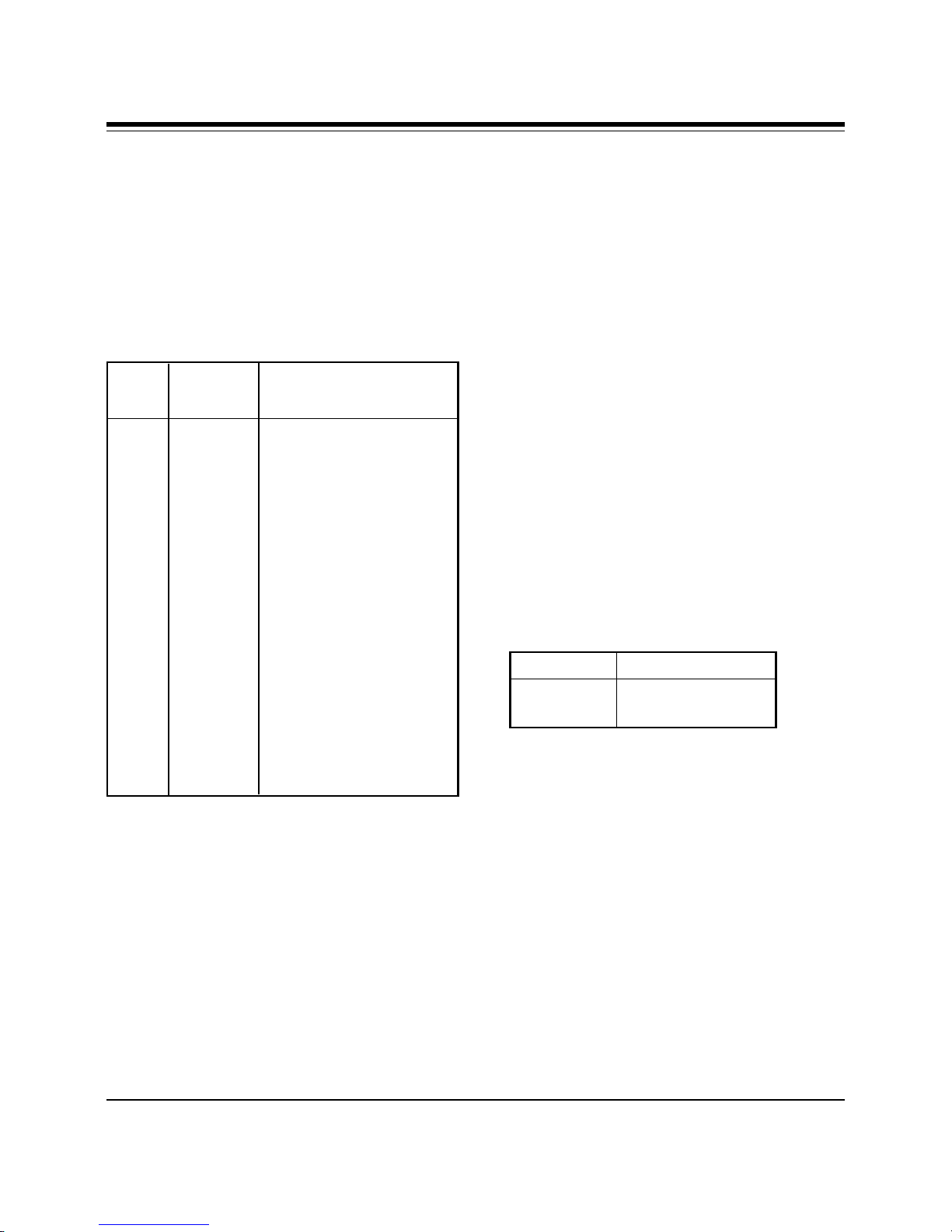
58
Subparameter Definitions
1. <mod> = a decimal number which
specifies the preferred modulation
(automode enabled) or the modulation
(automode disabled) to use in
originating or answering a connection.
The options are as shown below:
Modulation
<mod>
0 V.21 300
1 V.22 1200
2 V.22bis 2400 or 1200
3 V.23 1200*
9 V.32 9600 or 4800
10 V.32bis 14400, 12000, 9600, 7200,
11 V.34 28800, 26400, 24000,
64 Bell 103 300
69 Bell 212 1200
74 V.FC 28800, 26400, 24000,
* For V.23, originating modes transmit at
75bps and receive at 1200bps; answering
modes transmit at 1200bps and receive at
75bps. The rate is always specified at
1200bps.
Selected Possible rates (bps)
or 4800
21600, 19200, 16800,
14400, 12000, 9600, 7200,
4800, or 2400 (default)
21600, 19200, 16800,
14400
• The modem may not be able to
automatically switch from the current
modulation (specified by <mod>) to
some other modulation. For example,
there is no standard way to automode
from Bell 103 to V.23.
• The DTE may disable automode
operation (see <automode>).
• The DTE may constrain the range of
modulations available by specifying the
lowest and highest rates (see <min_rate>
and <max_rate> below).
2. <automode>=an optional numeric
value which enables or disables
automatic modulation negotiation.
Options are:
<automode> Option Selected
0 Automode disabled
1 Automode enabled
The default value is 1, which enables
automode. Note, however, there are
modulations for which there is no
automatic negotiation (e.g., Bell 212
(<mod>=69).
For <automode> = 0 (automode
disabled, i.e., fixed modulation):
The modem may also automatically
switch to another modulation
(automode), subject to the following
constraints:
SoundExpression
a. If <max_rate> is within the rates
supported by the selected modulation,
the selected rate is that specified by
<max_rate>.
Page 59

Example: +MS=9,0,1200,4800 selects V.32
4800bps fixed rate.
59
Example: +MS=10,1,1200,24000 selects
automoding down from V.32bis
14400bps.
b. If <max_rate> is greater than the
highest speed supported by the
modulation specified by <mod>, the
starting rate is the highest rate supported
by the selected modulation.
Example: +MS=9,0,2400,14400 selects
V.32 9600 or 4800bps.
c. To emulate N0S37=x command
sequence to select fixed mode operation,
specify the <max_rate> and <min_rate>
both to be the same requested speed, and
<mod> to be the modulation for that
speed.
Example: +MS=11,0,16800,16800 selects
V.34 16800bps fixed mode (no comparable
S37 command).
+MS=9,0,12000,12000 selects V.32
12000bps fixed mode (same as
N0S37=10).
b. To emulate N1S37=x sequence
command, specify the modulation and
the rate to start automoding down from
using <mod> and <max_rate>,
respectively. Set <min_rate> to 300 to
allow automoding all the way down to
V.21 300bps.
Example: +MS=11,1,300,16800 selects
automode starting at V.34 16800bps (no
comparable S37 command)
+MS=9,1,300,12000 selects automode
starting at V.32bis 12000bps (same as
N1S37=10).
3. <min_rate>= is an optional number
which specifies the lowest rate at
which the modem may establish a
connection. The value is decimal-coded
in units of bps, e.g., 2400 specifies the
lowest rate to be 2400bps. The default
is 300 for 300 bps.
For <automode> = 1 (automode enabled;
i.e., automatically selected speed and
modulation).
a. If <max_rate> is greater than the
highest rate supported by the modulation
specified by <mod>, the modem
automodes down from the highest rate of
selected modulation.
4. <max_rate>= is an optional number
which specifies the highest rate at
which the modem may establish a
connection. The value is decimal-coded
in units of bps, e.g., 14400 specifies the
highest rate to be 14400bps. The default
is 28800 for 28800bps.
Modem Command Reference
Page 60

60
Result Codes
Result Numeric
Code Value Description
CONNECT 9 Modem established a
0600 connection at 600 bps.
OK 0 Modem successfully
executed a command
line.
CONNECT 1 Connection made at 300
bps.
RING 2 Modem detected an
incoming call.
NO CARRIER 3 Modem lost or could
not detect a remote
carrier signal within the
Register S7 time.
ERROR 4 Modem found an error
in the command line.
CONNECT 5 Modem established a
1200 connection at 1200
1200bps.
CONNECT 10 Modem established a
2400 connection at 2400 bps.
CONNECT 11 Modem established a
4800 connection at 4800 bps.
CONNECT 12 Connection made at
9600 9600 bps.
CONNECT 13 Connected as data
7200 modem during an
answer.
CONNECT 14 Connection made at
12000 12000 bps.
CONNECT 15 Connection made at
14400 14400 bps.
CONNECT 16 Connection made at
19200 19200 bps.
NO 6 Modem did not detect a
DIALTONE dial tone within 5
seconds after going offhook.
BUSY 7 Modem detected a busy
signal.
NO ANSWER 8 Five seconds of silence
was not detected when
using the @ command
in the dial command
line.
SoundExpression
CONNECT 17 Connection made at
38400 38400 bps.
CONNECT 18 Connection made at
57600 57600 bps.
CONNECT 19 Connection made at
115200 115,200 bps.
CONNECT 22 Modem returns this
75TX/1200RX result code when upon
establishing a V.23
originate connection
when the modem has
Page 61

Result Numeric
Code Value Description
been instructed to
report the DTE
speed to the DTE
upon connecting.
CONNECT 23 Modem returns this
1200RX/75RX result code when
upon establishing a
V.23 answer
connection when
the modem has
been instructed to
report the DTE
speed to the DTE
upon connecting.
61
CARRIER 40 Carrier rate of 300 bps.
300
CARRIER 44 V.23 backward channel
1200/75 has been detected.
CARRIER 45 V.23 forward channel
75/1200 has been detected
CARRIER 46 Carrier rate of 1200 bps.
1200
CARRIER 47 Carrier rate of 2400 bps.
2400
CARRIER 48 Carrier rate of 4800 bps.
4800
DELAYED 24 For X4; when a call
fails to connect and
the number dialed
is ‘delayed’ due to
country blacklisting
requirements.
BLACKLISTED 32 For X4; when a call
fails to connect and
the number dialed
is considered
‘blacklisted’.
FAX 33 A fax modem
connection is
established.
DATA 35 A data modem
connection is
established.
CARRIER 49 Carrier rate of 7200 bps.
7200
CARRIER 50 Carrier rate of 9600 bps.
9600
CARRIER 51 Carrier rate of 12000
12000 bps.
CARRIER 52 Carrier rate of 14400
14000 bps.
CARRIER 53 Carrier rate of 16800
16800 bps.
CARRIER 54 Carrier rate of 19200
19200 bps.
CARRIER 55 Carrier rate of 21600
21600 bps.
Modem Command Reference
Page 62

62
Result Numeric
Code Value Description
CARRIER 56 Carrier rate of 24000
24000 bps
CARRIER 57 Carrier rate of 26400
26400 bps.
CARRIER 58 Carrier rate of 28800
28800 bps.
CONNECT 59 Connect speed of 16800
16800 bps.
CONNECT 61 Connect speed of 21600
21600 bps.
CONNECT 62 Connect speed of 24000
24000 bps.
CONNECT 63 Connect speed of 26400
26400 bps.
CONNECT 64 Carrier rate of 28800
28800 bps.
COMPRESSION:
CLASS 5 connected in MNP
66 The modem has
class 5 and
COMPRESSION
message reporting has
been enabled.
COMPRESSION
PROTOCOL: 70 Modem has connected
NONE* without any form of
PROTOCOL: 77 Modem has connected
LAPM* in the V.42 LAPM
PROTOCOL: 80 Modem has connected
ALT* in the MNP mode of
PROTOCOL: 81 Modem has connected
ALT* CELLULAR in the MNP10 mode.
* PROTOCOL message reporting has been
enabled.
+FCERROR +F4 Fax carrier error.
: 69 The modem has NONE
connected without
data compression and
COMPRESSION
messagereporting has
been enabled.
error connection.
mode of error
correction.
error correction.
COMPRESSION:
V.42bis connected in V.42bis
SoundExpression
67 The modem has
and COMPRESSION
message reporting has
been enabled.
Page 63

Appendix L: Glossary of
Audio Terms
63
amplitude. The variation in a sound signal
producing varying levels of loudness. Measured
in decibels (dB).
analog sound. Recorded sound depicted by
fluctuations in amplitude.
bits per sample. The number of bits employed
to record information from a single sample
when recording digital sound. See Sampling.
CD quality. Recording quality similar to that of
a compact disc player. This means that 16 bits of
information are recorded for every sample
taken. See Bits Per Sample and Sampling.
decibel (db). A means of measuring amplitude.
digital sound. Recorded and stored sound as a
series of numerical values rather than
fluctuations in amplitude.
MPU-401. A UART on the MIDI port which
allows MIDI interface to transmit and receive at
32.5K baud (see Appendix E for more
information).
pitch. A sound’s tone, usually determined by
the sound’s frequency.
sample. A measurement of sound taken during
a certain duration. In digital recording,
sampling means recording voltages which make
a sound as a sequence of numerical values
representing the sound’s amplitude.
sound file. Any file which holds sound data.
Examples: files with .MID file name extensions
are compatible with the MIDI standard (see
above); a file with a .WAV file name extension is
a standard Microsoft file format for storing
waveform audio data. See Waveform and wave
file.
line-in. A connector on audio equipment to
which a device like a CD-player or tape cassette
player may be attached. See also Line Out.
line out. A connector on audio equipment to
which audio components can be attached such
as stereo speakers. See also Line In.
MIDI. Musical Instrument Digital Interface. A
standard which allows for the exchange of data
between two music synthesizers or a
synthesizer and a computer. Sound data may be
communicated from the synthesizer to the
computer and stored as a MIDI file. Or, a MIDI
file can be transmitted to the synthesizer for
playback.
timbre. How the ear identifies and classifies
sound. Example: the timbre of the same note
played by two different instruments (flute and
tuba) will not be the same.
voice annotation. Embedding of a voice
message into a document for later playback.
wave file. A standard Microsoft file format for
storing waveform audio data.
waveform. A graph showing the amplitude of a
sound over a particular interval of time. Any
portion of that interval is a sample.
Modem Command Reference
Page 64

64
Appendix M: Glossary of
Modem Communication
Terms
A
algorithm. A formula or procedure which
employs various methods defining how data
is to be used to give a prescribed result.
analog signals. Signals which can vary over a
continuous range (e.g., the human voice over
conventional telephone lines). Analog
circuitry is more subject to distortion and
noise, but it is more capable of handling
complex signals than are digital signals which
can have only discrete values.
ARQ. Automatic ReQuest for retransmission.
A type of communications link where the
receiver asks the transmitter to re-send a
block of data when errors are detected.
B
Bell standards. Refers to the U. S. modulation
protocol standards developed by the former
AT&T Bell Systems such as Bell 103 (300bps
transmission) and Bell 212A (1200bps
transmission).
bit-mapped registers. An S-register which
contains multiple bit-oriented values.
blind dialing. An automated process
whereby the modem goes off-hook and dials
without waiting for a dial tone. This is
prohibited in many countries.
block transfer control. Determines whether
or not the modem uses block or stream mode
during an MNP connection. In stream mode,
MNP sends data frames in varying length.
Block mode sends fixed data frames of 256
characters.
bps. bits per second.
ANSI. American National Standards
Institute. A non-profit, private industry
association which governs most USAstandards setting agencies.
ASCII. Acronym for American Standard
Code for Information Interchange. ASCII is
an ANSI character set. The standard ASCII
character set consists of 128 decimal numbers
(0-127) for letters of the alphabet, numerals,
punctuation marks, and common special
characters. The extended ASCII character set
extends to 255 characters and contains special
mathematical, graphics, and foreign
characters.
asynchronous communications. A method of
transmission in which one character is sent
one bit at a time; also referred to as serial
transmission.
break handling. Determines how the modem
responds when a BREAK signal is received
from either the DTE (Data Terminal
Equipment or computer/terminal) or the
remote modem. This is controlled by the
MNP-based AT extended command \K. A
break signal is represented on the
communications line by a steady space signal
for a significant length of time. Break signals
may be activated from the keyboard by
pressing the BREAK key or the control
(CTRL) and C keys.
C
CCITT. Consultative Committee for
International Telephone and Telegraph. This
advisory organization is part of the ITU
(International Telecommunication Union)
which is an agency of the United Nations.
Organization recently renamed International
Telecommunications UnionTelecommunications Standard Sector (ITU-T)
SoundExpression
Page 65

65
command mode. The modem is in command
mode when it is turned on or reset, when it
loses its connection to a remote modem,
when it is in on-line mode, or when escape
characters (+++) are typed. To transmit data,
the modem must be in data mode. The
modem does not transmit data when in
command mode.
communications protocol. A set of
procedures which controls how a data
communications network operates.
D
DCD. Data Carrier Detect. Indicates to the
terminal device that the modem is receiving a
valid carrier signal from a remote modem.
The carrier is a tone at a specified frequency.
DCE. Data Communications Equipment. The
local and/or remote modem. A DCE is
usually connected to a DTE.
DTE. Data Terminal Equipment. The
computer or terminal, either local (yours), or
the remote (the one you’re communicating
with). A DTE is usually connected to a DCE.
DTR. Data Terminal Ready. The computer
issues this signal to the attached modem
indicating that it is ready to receive data.
data compression. A technique that examines
transmitted data for redundancy and replaces
strings (groups) of characters with special
codes which the receiving modem interprets
and restores to its original form. Transmission
of compressed data results in shorter connect
times and hence cost savings for connect
charges. Data compression is sometimes
called “source encoding”.
data mode. The modem is in data mode when
a connection has been established with a
remote modem and sends a CONNECT
response confirming the connection. User
data may then be transmitted or received.
dial modifier. Dial modifiers are special
characters appended to the ATD command
which instruct the modem how to place a
call.
digital signal. A discrete signal which can
only take on one of several (usually only two)
discrete levels in contrast to analog signals
which can take a continuous range of levels.
E
error detection and correction. The
transmitting modem attaches a special pattern
(called a frame check sequence) calculated
according to a prescribed algorithm from
user-defined data to the end of a block of
data. The receiving modem performs the
same algorithm and compares it to the one
with the transmitted data. If these match,
then the block of data has been received
correctly. If not, the block of data is retransmitted until no errors are detected.
escape sequence. Also referred to as the
escape command. This special command is
entered as three plus symbols (+++) and
places the modem in command mode and
interrupts user data transmission, but does
not terminate the data connection. This allows
the entering of commands while the
connection is maintained.
extended AT-command. Extended commands
were developed to provide greater
functionality and control over modem
operations than is available from the basic AT
command set.
Glossaries
Page 66

66
F
fax mode. The modem is in fax mode when,
through use of fax communications software,
it can send and receive faxes, print and
display fax files, convert files to fax-files, and
set certain fax-related features. Note: the
modulation protocol used by the modem in
fax mode is also different from the usual data
mode modulation.
flow control. Compensates for the difference
between the rate at which data reaches a
device and the rate at which the device
processes and transmits. The two common
types of flow control are RTS/CTS signaling
(a hardware based method, employing an
electrical signal) and XON/XOFF (a softwarebased method using standard ASCII control
characters to pause or resume transmission).
The \G command controls XON/XOFF flow
control.
full-duplex. Two-way simultaneous
transmission between modems, which may
occur via a four-wire circuit on a leased line,
or with a two-wire connection when the
frequency bandwidth is divided into two
distinct channels, or when echo cancellation
is employed (e.g., Bell 103, 212, and V.22 use
frequency division, while V.32 uses echo
cancellation).
G
guard tone. Guard tones are used in the
United Kingdom and other countries. This
requires that the modem transmit an 1800-Hz
tone after it sends an answer tone. The guard
tone is controlled by the &G command.
Guard tones are not used in the U.S.A.
H
half-duplex. Signal flow in both directions,
but only one way at a time with each modem
alternating between send and receive.
Hayes-compatible. Hayes Microcomputer
Products, Inc. developed the AT command set
which has become a de facto industry
standard. Hayes commands are always
initiated with an AT (attention code) prefix.
hook flash. The dial modifier “!” causes the
modem to go on-hook (hang-up) for one-half
second. Also controlled by the ATH
command.
L
LAPM. Link Access Protocol Modem. A V.42
ARQ type of error correction protocol where
LAPM may be activated with or without
V.42bis data compression.
leased line. Also referred to as a private line.
A leased line is obtained from a
communications company (carrier) to
provide a transmission medium between two
points. The line consists of a permanent
dedicated circuit between two points, or to set
of previously arranged points. The cost of the
line is usually based on the distance between
locations. This is in contrast to switched or
dial-up lines, which can be connected to any
point on the network.
line modulation. The means by which a
carrier is varied to represent a signal carrying
information. In a modem, the user ’s digital
data is used to modulate the modem’s
transmitter’s carrier or carrier to allow the
digital signal to be carried over analog
facilities.
SoundExpression
Page 67

67
long space disconnect. Determines whether
or not modem disconnects when it receives a
continuous break from a remote modem.
Controlled by the ATY command.
loopback tests. There are four types of
loopback tests which are as follows: (1) the
local digital loopback tests the operation of
the DTE, including whether or not data is
leaving the terminal or computer port; (2) the
local analog loopback tests the digital and
analog circuits of the modem; (3) the remote
digital loopback checks the operating
condition of the line and remote modem; (4)
the remote analog loopback tests the line to
the remote modem.
M
MNP. Microcom Networking Protocol. A
series of data communications protocols
developed by Microcom for full-duplex, errorfree communications.
take when a desired connection cannot be
made (e.g., hang-up, direct mode connect,
normal mode connect).
non-volatile RAM. Also NVRAM. Random
access memory whose data is retained when
power is turned off. This is especially useful
for modems to store user-defined default
configuration settings and frequently used
telephone numbers. This information would
be loaded into modem RAM at power-up.
O
on-line state. Same as data mode. To transmit
or receive data, the modem must be in the online state. When placing a call, the modem is
put on-line with the dial command.
P
PBX. Private Branch Exchange. A telephone
switch at a customer site.
make/break ratio. The &P command controls
the ratio of the off-hook (make) to on-hook
(break) interval used by the modem when it
pulse dials. &P0 selects a 39%/61% make/
break ratio for use in the U.S. &P1 selects a
33%/67% make/break ratio for use in the
United Kingdom and Hong Kong. The &P
command is NOT allowed in some countries.
modulation handshake. Also referred to as
Automode Enable and is controlled by the
ATN command. This determines whether or
not the modem must connect at a particular
speed, or allow connection at any speed
supported by both modems.
N
negotiation fallback. Controlled by S-
Register 36 as part of the V.42 protocol.
Setting this register indicates what action to
pulse dialing. Also referred to as rotary
dialing, i.e., dialing with the older-style rotary
dial wheel. The dial modifier ATDP sets the
modem to pulse dialing, which is the default
method as opposed to tone dialing (pushbutton touch-tone) which is enabled with
ATDT. All telephone exchanges will accept
older-style pulse dialing and most exchanges
will accept modern tone-dialing. Tone dialing
is faster and more reliable since mechanical
relays and their inherent failure mechanisms
are avoided.
R
result code. A response sent by the modem
after executing a command. The response
reports the modem’s status or the progress of
a call and can take the form of either digits
(numeric) or words (verbose). Issuing a V1
command enables word responses. A V0 (V-
Glossaries
Page 68

68
zero) command enables numeric responses.
The Q1 command disables their use entirely.
Example: “OK” (word), or 0 (numeric)
indicates that the modem successfully
executed a command.
retrain. An adjustment process performed
when one of the modems detects signal
distortion or line noise which threaten data
integrity.
RTS/CTS. Request to Send/Clear to Send.
RTS and CTS are two control signal lines
between the modem (DCE) and terminal
(DTE) which allow the terminal to control the
flow of information. See also flow control.
S
sleep inactivity timer. Determines the length
of time the modem operates in normal mode
with no activity before entering low-power
“sleep” mode.
trellis coding. A method of modulation
which targets specific modulation points.
Signals falling outside of these points are
treated as line noise, thus ensuring greater
noise immunity over a given line. QAM
(Quadrature Amplitude Modulation)
functions similarly, but has a broader
tolerance and results in lesser noise immunity
than trellis coding.
X
XON/XOFF. XON and XOFF are the names of
two different flow control characters. See also
flow control.
Acknowledgments
The Complete Modem Reference. Gilbert Held.
John Wiley & Sons, Inc.
Upgrading and Repairing PCs. (Second
Edition). Que Corporation.
split-speed direction. Determines which
direction (transmit or receive) has the 75bps
channel and which has the 1200bps channel.
standard AT-command. The basic AT
command set, originated by Hayes
Microcomputer Products, Inc.
synchronous communications. A method of
transmission in which data bits are sent
continuously at the same rate under the
control of a fixed frequency clock signal.
T
touch-tone dialing. Push-button tone dialing
as used on contemporary phone sets. The dial
modifier ATDT sets the modem to “tone”
mode. Tone dialing is faster and more reliable
than older-style pulse dialing.
©1995. All rights reserved. No reproduction
of this document in any form is allowed
without permission in writing from the
vendor. The vendor is not liable for any
damage resulting from technical or editorial
errors or omissions contained in this
document. The information in this manual is
subject to change without notice. Revisions to
the product(s) in this manual may occur at
any time without notice.
Trademarks
All references to computer systems, software,
and peripherals use trademarks owned by
their respective manufacturers.
Publication Date: August, 1995
Printed in the U.S.A.
SESRSALL.PM5
SoundExpression
Page 69

69
Index
A
Amplified device 16
AT Commands, basic 46-48
AT Commands, extended 48-50
AT Commands, MNP 50-51
AT Commands, modulation select 57-59
AT Commands, V.42/V.42bis 52
Audio Data Rate 33
B
Board Connectors 11
C
Compliance Information 41-42
Configuration Settings 35
Connecting for Modem Use 14
Connecting to an IDE CD-ROM
Drive 12-13
Connection to External Devices 11
Connection to Internal Devices 11
D
DSVD (Digital Simultaneous Voice and
Data) 9
Data Capabilities 25
Default Configuration 35
Diagnostics 34
Digital Sound 39
Driver Installation, Windows 3.1/
DOS 18-22
Driver Installation, Windows 95 23-24
E
External Audio-in Devices 15
External Audio-out Devices 16
F
Fax Data Rate 33
FCC Statement 41
Features 8-9
Feature Comparison 8-9
G
Glossary of Audio Terms 63
Glossary of Modem Communication
Terms 64-68
I
IDE CD 35
Installing Your New
SoundExpression 10
Introduction 8-9
J
Joystick/MIDI Device 17
K
Keyboard synthesizer 17
L
L-IN (LINE IN) connector 15
L-OUT (LINE OUT) 16
M
MIC connector 15
Microphone Requirements 36
MIDI Interface 38
Page 70

70
MIDI-compatible keyboard
synthesizer 17
Modem Addresses 35
Modem Commands 46-62
Modem Data Rate 33
Modem Functions and Features 25-26
Modem Problems 31-32
MPU-401 Interface 35
R
Replacing Existing Devices 10
Result Codes 60-62
Return Merchandise Authorization
(RMA) number 43
S
S-Registers 53-56
Servicing Your Boca Product 43-44
Sound Blaster 35
Sound Blaster CD-ROM 35
Sound Test Utility (SNDINIT) 19-22
Speaker Requirements 36
Surround Sound (SRS) 8
SPK (SPEAKER OUTPUT) 16
System Requirements 9
W
Warranty Information 45
Wave Table Car d Installation 37
Windows Sound System 35, 40
Y
“Y” cable 17
T
Technical Assistance 3
Technical Specifications 33-34
Technical Support 3-4, 43
Technical Support, On-Line 4
Testing the Connection 26
Troubleshooting 27-32
U
Unamplified device 16
SoundExpression
Page 71

71
Page 72

72
SoundExpression
PN 9476
Rev. 1.0
 Loading...