

Page 1
RemoteCam4™ Quick Install
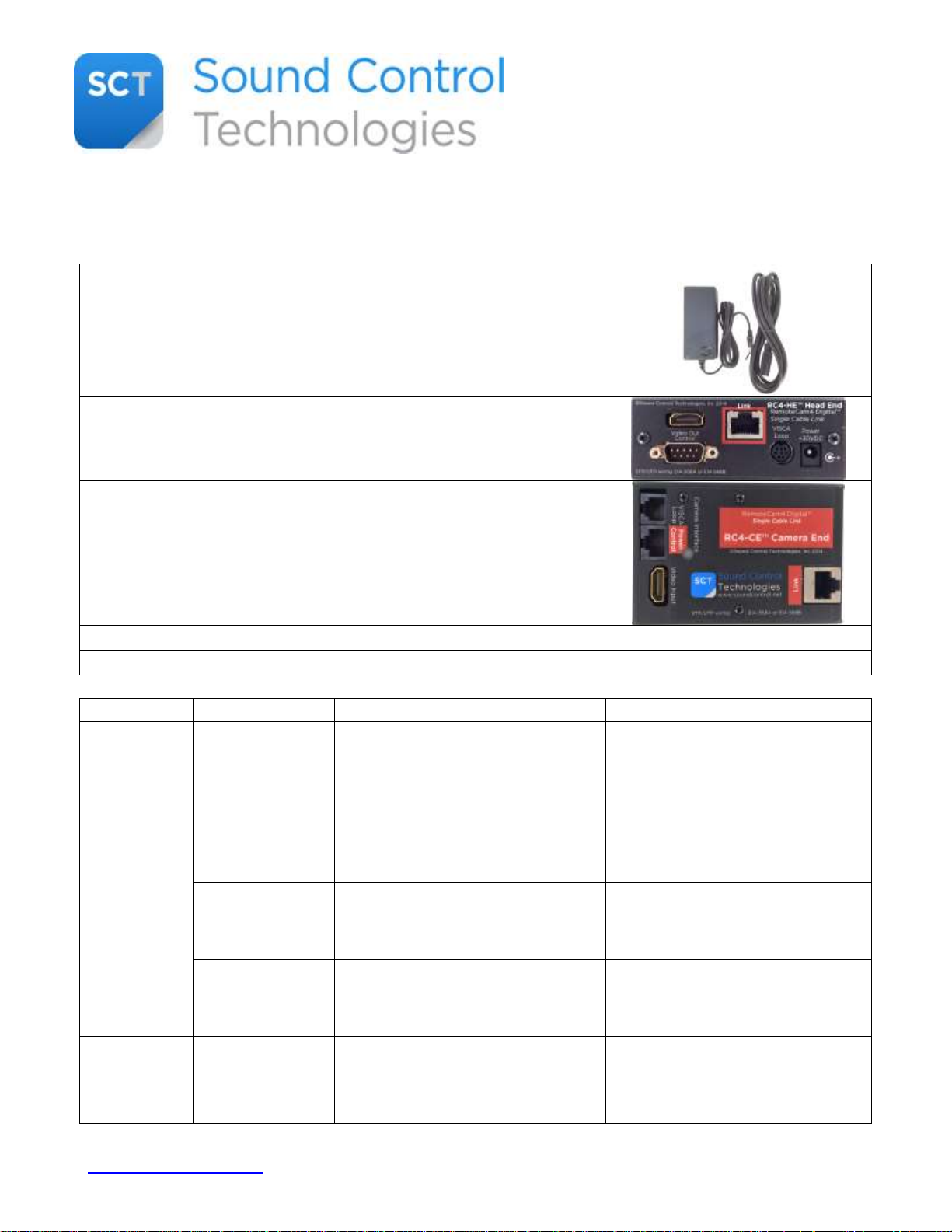
1 Power Supply & cord (WPS-12 or WPS-14) to provide power
for the RemotCam4™ electronics as well as the remote camera
up to 300’ from the head end. All the RemoteCam™ kits use the
same power supply. The power supply is AC 100-240V~47-63HZ
compliant.
1 RemoteCam4™ Head End Module (RC4-HE) which provides
system power, control interface (HDMI CEC, RX, TX, GND & IR)
for the camera & one HDMI video output for the codec.
1 RemoteCam4™ Camera Module with PowerSniffer™ (RC4-CE)
that provides camera power, control (HDMI CEC, RX, TX, GND &
IR) and HDMI video input for the camera
Documentation
Specific cables (P/N according to the following chart)
Company
Codec
Camera
SCT Kit
Cables
Cisco
C40, C60, C90 &
SX80
PrecisionHD
1080p 12X, 4xS1
& 720p
RC4-PHD
RCC-C001/RCC-C002/RCC-C003
RCC-H01/RCC-H003/RCC-H004
SX20
PrecisionHD
1080p 12x
RC4-PSA
RCC-C001/RCC-C002
RCC-H009
C40, C60, C90 &
SX80
PrecisionHD
1080p 4xS2, 2.5x
RC4-PSB
RCC-C009
RCC-H01/RCC-H003/RCC-H004
SX20
PrecisionHD
1080p 4xS2, 2.5x
RC4-PSX
RCC-C009
RCC-H009
Lifesize
220
Icon 600
Icon 800
10X
Camera S
RC4-L22
RCC-C001
RCC-C028
RCC-H001
DATE: 8/28/15
PRELIMINARY
Thank you for choosing the Sound Control Technologies’ RemoteCam4™ camera integration kit.
Included in each RemoteCam4™ kit will be:
www.soundcontrol.net 203-854-5701 ©SOUND CONTROL TECHNOLOGIES, INC. 2015
Page 2
Polycom
Group Series
300, 500 & 700
EagleEye IV
RC4-E4P
RCC-C030
RCC-H030
Sony
Cisco C40, C60,
C90, SX80
EVI-HD3/VDI
EVI-HD7/DVI
RC4-SHC
RCC-C004/RCC-C005/RCC-C006
RCC-H001/RCC-H003/RCC-H004
Generic
Controller
EVI-HD3/VDI
EVI-HD7/DVI
EVI-H100V
RC4-SHD
RCC-C004/RCC-C005/RCC-C006
RCC-H001/RCC-H003/RCC-H004
Generic
Controller
SRG-120
SRG-300
RC4-S12
RC4-S30
RCC-C001/RCC-C005/RCC-C006
RCC-H001/RCC-H004/RCC-H010
PCS-XG100S
SRG-120H
RC4-X12
RCC-C001/RCC-C005/RCC-C006
RCC-H040
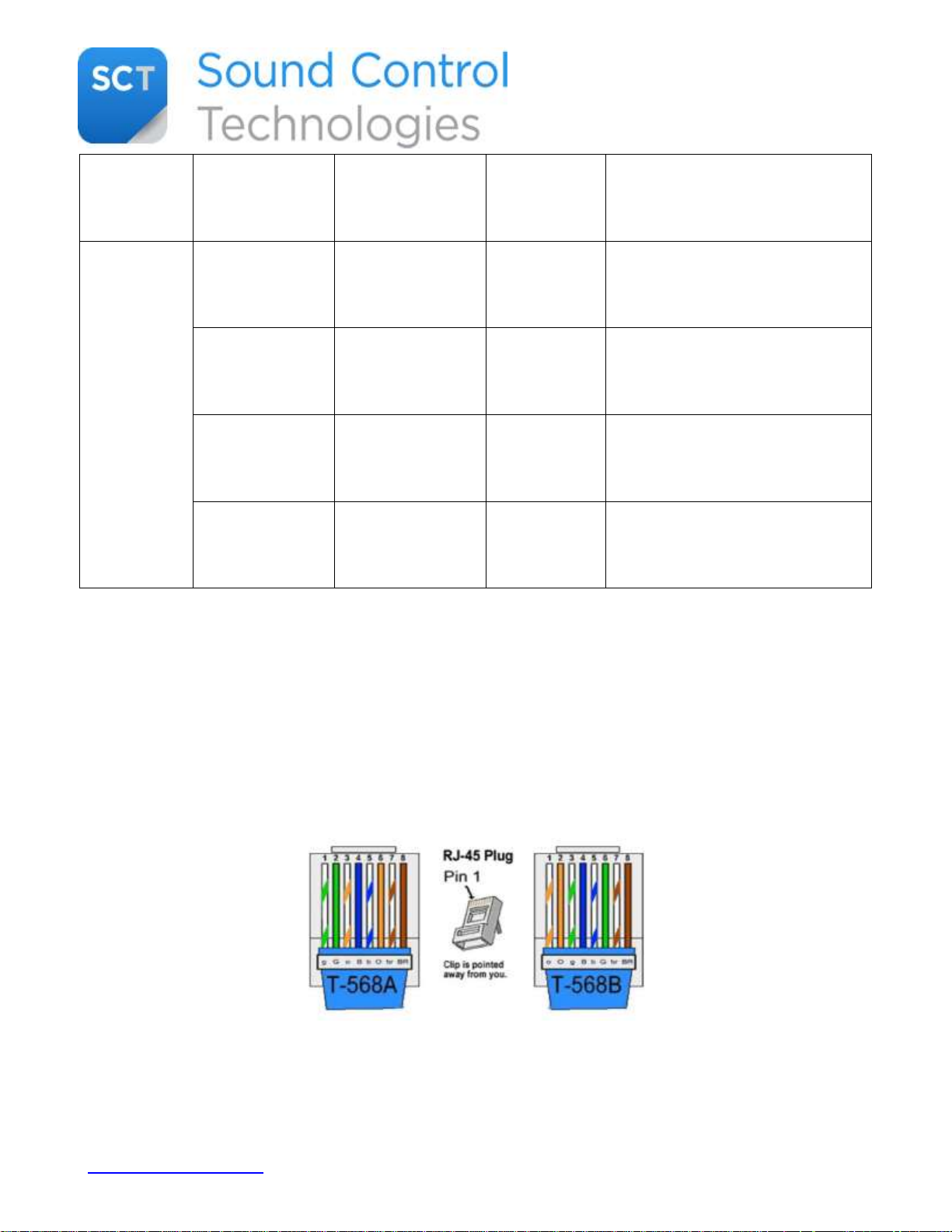
To proceed with the installation, insure that you have installed one CAT5e or CAT6 cable between
the camera installation site and the codec installation site.
The cable must be wired for either UTP 568A or UTP 568B. For your convenience, you can use the
following scheme:
www.soundcontrol.net 203-854-5701 ©SOUND CONTROL TECHNOLOGIES, INC. 2015
Page 3
Step 1
Test and verify the Cat5e or Cat6 cable for UTP 568A or 568B wiring.
Step 2
Install the RC4-HE Head-End Module at the rack/equipment location.
Connect the Cat5e or Cat6 cable to the RC4-HE module.
Connect the power supply to the RC4-HE Module.
Step 3
Using the PowerSniffer™, at the camera location connect to the UTP cable. It should display 8 green
LED’s.
Any other result, please re-terminate.
Step 4
Disconnect the power supply from the RC4-HE
Step 5
Connect the CAT5e or CAT6 cable to the RC4-CE Camera Module.
Step 6
Connect provided cables between codec and RC4-HE module.
Step 7
Connect provided cables between camera and RC4-CE module.
Step 8
Connect the power supply to the RC4-HE module
Step 9 Enjoy!
To install the RemoteCam4™ Kit, follow the step-by-step guide:
www.soundcontrol.net 203-854-5701 ©SOUND CONTROL TECHNOLOGIES, INC. 2015
 Loading...