

Page 1
RemoteCam5™
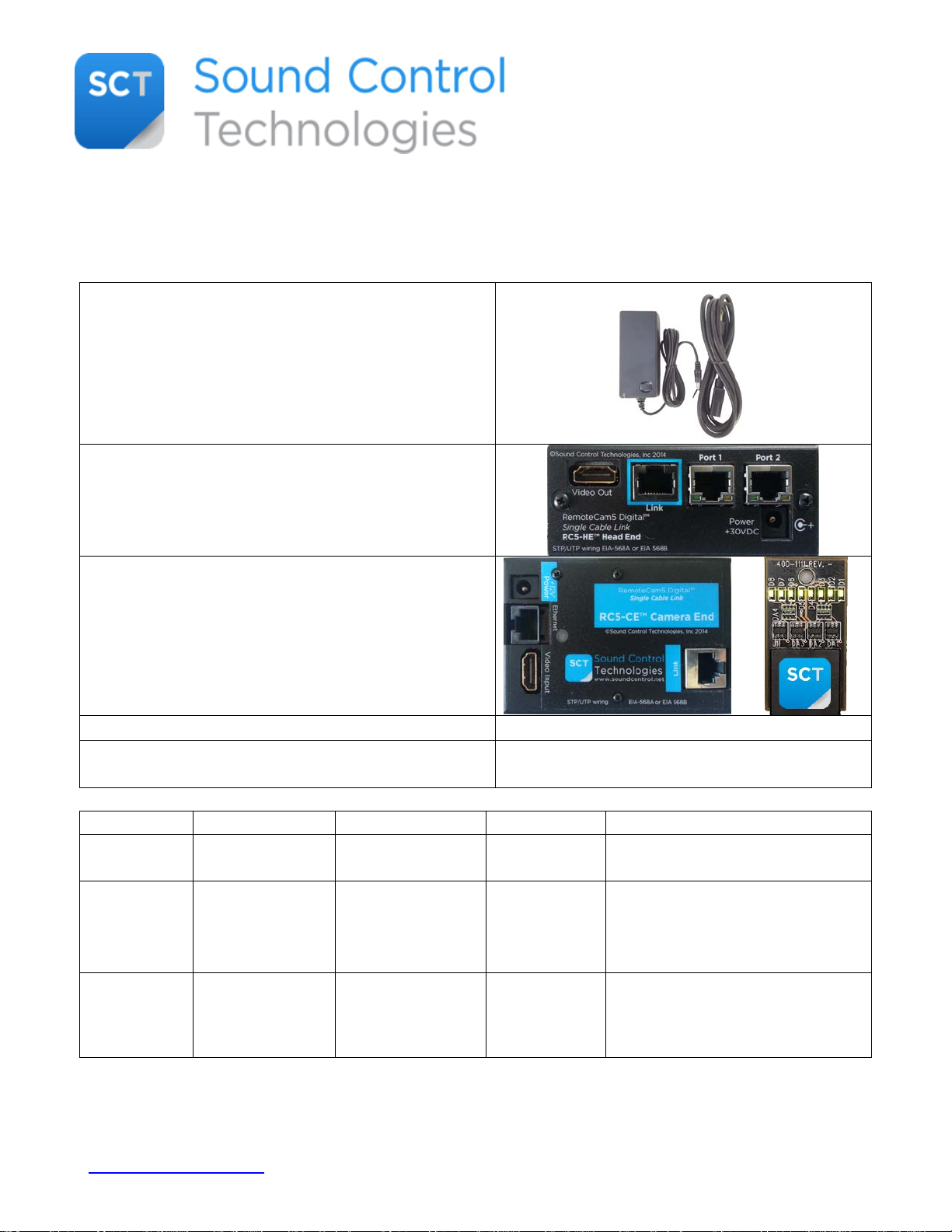
• 1 Power Supply & cord (Currently all RemoteCam
compliant.
• 1 RemoteCam5™ Head End Module (RC5-HE)
• 1 RemoteCam5™ Camera Module with
• Documentation
• Specific cables (P/N according to the following
chart)
Company
Codec
Camera
SCT Kit
Cables
RCC-C001/RCC-C002/PPC-003
RCC-H001/RCC-H016
AW-RP50
Controller
Panasonic
AW-UE70
Installation Instructions
Thank you for choosing the Sound Control Technologies’ RemoteCam5™ camera integration kit!
Included in each RemoteCam5™ kit will be:
Kits utilize the WPS-12) to provide power for the
RemoteCam5™ electronics as well as the remote
camera up to 300’ from the head end. All the
RemoteCam™ kits use the same power supply.
The power supply is AC 100-240V~47-63HZ
which provides system power, control interface
(Ethernet & IR) for the camera & one HDMI video
output for the codec.
PowerSniffer™ (RC5-CE) that provides camera
power, control (Ethernet & IR) and HDMI video
input for the camera
Cisco SX80 Precision 60 RC5-P60
Panasonic
Sony
AW-RP120
Generic
RMP10 or
Generic
Controller
AW-HE130
AW-HE40
Sony
SRG-120H
SRG-300H
RC5-P13
RC5-P40
RC5-P70
RC5-SRG
RCC-C001/RCC-C002/PPC-005
RCC-H001/RCC-H016
RCC-C001/RCC-C002/PPC-004
RCC-H001/RCC-H016
To proceed with the installation, insure that you have installed one CAT5e or CAT6 cable between
the camera installation site and the codec installation site.
www.soundcontrol.net 203-854-5701 ©SOUND CONTROL TECHNOLOGIES, INC. 2017
Page 2
Minimum distance should be approximately 30’/9M.
• Step 1
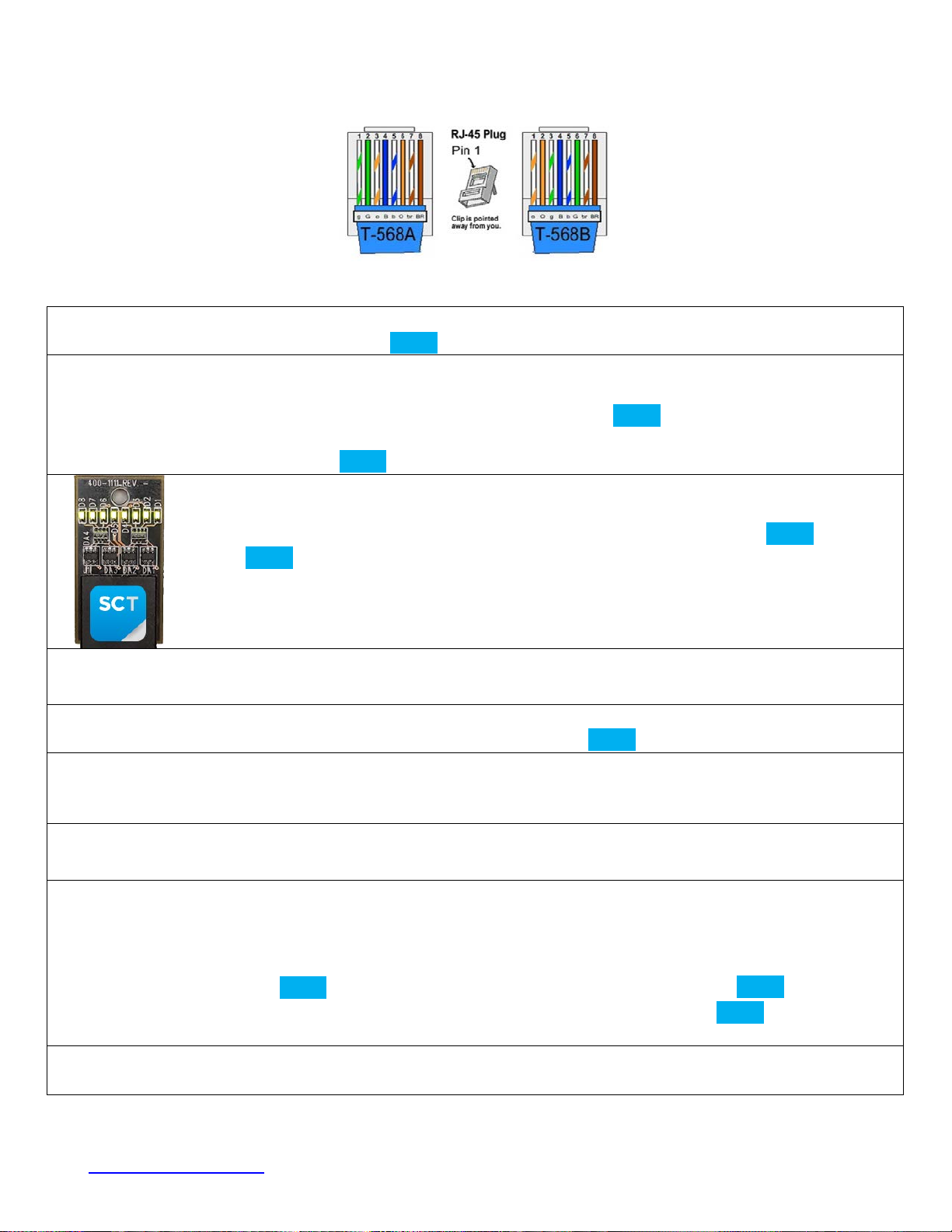
Test and verify the Cat5e or Cat6 cable for UTP 568A or 568B wiring: See steps 2 & 3.
• Step 2
Wait to connect the cable to the RC5-CE until steps 3 & 4 are completed.
• Step 3
Disconnect the power supply from the RC5-HE
• Step 5
• Connect the CAT5e or CAT6 cable to the RJ45 connector labelled to the RC5-CE Camera Module.
• Step 6
can connect to Port 1 or Port 2 of the RC5-HE.
• Step 8
• Step 9
• Enjoy!
The cable must be wired for either UTP 568A or UTP 568B. Please use the above scheme.
To install the RemoteCam5™ Kit, follow this step-by-step guide:
•
• Install the RC5-HE Head-End Module at the rack/equipment location.
• Connect the Cat5e or Cat6 cable to the RJ45 connector labelled on the RC5-HE module.
• Connect the power supply to the RC5-HE Module.
•
At the camera location connect the PowerSniffer™ to the CAT5e or CAT6 cable.
If the cable is properly terminated it will display 8 green LEDs. See image at left.
Any other result, please re-terminate.
• Step 4
•
• Connect provided cables between codec and RC5-HE module. The codec (or second camera or touch panel)
• Step 7
• Connect provided cables between camera and RC5-CE module.
• Connect the power supply to RC5-HE module
• LED Behavior:
• Head-End Module HDCP LED: Blinking = HDCP Inactive, Solid = HDCP Active
• Head-End Module LED: Blinking Red = No Link, Blinking Red to Green = Active
• Camera Module: LED will be Red until Link is established, Solid Green when is Active
www.soundcontrol.net 203-854-5701 ©SOUND CONTROL TECHNOLOGIES, INC. 2017
 Loading...