

Page 1
OPERATION MANUAL
SA611, SA612, SA613
EMITTER PANELS
SOUND ASSOCIATES, INC.
424 West 45th Street, New York, NY 10036
Tel: (212)757-5679 Fax: (212)265-1250
Toll free: 888-772-7686
Home page: www.soundassociates.com
Page 2

TABLE OF CONTENTS
INTRODUCTION..........................................................................................................2
INFRARED LISTENING SYSTEM 600 FEATURES.....................................................2
UNPACKING UNIT.......................................................................................................3
INSTALLATION DESIGN/EMITTER POSITIONING.....................................................3
Room Size........................................................................................................3
Seating Rake....................................................................................................4
Obstructions.....................................................................................................4
Wall and Ceiling Color......................................................................................4
Extraneous Light...............................................................................................4
MOUNTING EMITTER PANEL.....................................................................................5
CABLING.....................................................................................................................5
FAILURE/POWER INDICATORS................................................................ .................7
TROUBLESHOOTING.................................................................................................7
SERVICE OR REPAIRS.................................................................................................8
TECHNICAL SPECIFICATION.....................................................................................9
ACCESSORIES ...........................................................................................................9
WARRANTY............................................................................................................... 10
TYPICAL SYSTEM SCHEMATIC................................................................ ...............11
Page 3

INTRODUCTION
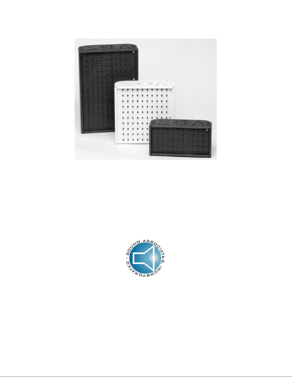
The Sound Associates SA611, SA612, and SA613 are high-powered infrared emitter panels.
The emitter panel transforms a frequency modulated signal, generated by an infrared modulator
or transmitter, into infrared light invisible to the naked eye. In contrast to a radio system, the
transmission is contained within the room it is broadcast; therefore, adjacen t rooms can utilize
the same infrared frequency without interference.
The 600 Series emitter panels work in conjunction with the SA601F Transmitter, PS24 Power
Supply, and SA650 Series Receivers. These emitters are powered by 24 to 30 volts DC from
an emitter power supply and activated by the carrier signal from the transmitter. One power
supply can power a total of 200 diodes. Therefore, each power supply will power a maximum of
either four SA611’s, two SA612’s, one SA613 and one SA611, or any combination.
To ensure proper set up and use of the system, the following instructions should be read
completely before attempting to install any equipment. If you require further assistance, please
call our Customer Service Department Monday-Friday 10:00 am - 5:3 0 pm at (888) 772-SOUND
(7686).
INFRARED LISTENING SYSTEM 600 FEATURES
Infrared Technology
Feature Advantage
Wireless Receivers No pre-registered seating
No “deaf section”
Easy distribution
Wireless signal tran smission by Infrared light
as compared to RF transmission
The audio signal is frequency modulated at 95
kHz or 250 kHz
SA611, SA612 & SA613 Emitter Panels
Feature Advantage
Powered by low voltage Eliminates the need for 120 VAC at each emitter
Infrared diodes are activated when modulated
audio signal is present
Fault Circuit Indicates diode or voltage regulator failure
New switching voltage regulator Increases efficiency by 20%
Removable front plate Allows for painting of emitter panel to blend into its
Connected to power supply via a single 18gauge, 2-conductor shielded cable
Full three-year warranty Insures years of trouble free use
Confidentiality; signal will not pass through walls or
curtains
No interference from common radio signals
Superior audio quality
Industry standard
Headsets are interchangeable with other home and
large area systems
location
Reduces installation time and cost
Lengthens diode life
Helps troubleshoot wiring problems
surroundings
Supplies low voltage and audio signal via one cable
Saves on installation time and cost
- 2 -
Page 4
UNPACKING UNIT
As soon as the shipment is received, inspect the unit and all components for damage incurred
by shipping. If the unit is damaged due to shipping, please keep all packing material and
contact the shipping company as soon as possible. Only the consignee may institute a claim
against a carrier if damage has occurred in shipping, however, Sound Associates will assist the
client in any such event.
Equipment enclosed:
1 SA611, SA612 or SA613 Emitter Panel
1 Instruction manual
3 Emitter Cable Stake-ons
If the unit fails to operate up to specification please contact your nearest Sound Associate s
dealer or Sound Associates’ Customer Service Department at (888) 772-SOUND (7686).
INSTALLATION DESIGN/EMITTER POSITIONING
One of the most important parts of the installation is the emitter layout. The emitters produce
the infrared light on which the audio signal is carried and must be in direct view of the seating
area. The carrier behaves like visible light. A blocked emitter will cause a shadowing effect on
the audience, allowing only the non-shadowed areas to receive the audio signal. The
installation design must take into consideration the seating rake, any balconies or overhangs,
columns, and any projections that may obstruct the infrared light.
3R
1R
1L
3L
3
1
2R
2L
2
color, and 5) extraneous light.
Room Size
The sheer size of the room in which the infrared system will be installed is the largest
consideration in the emitter design. This section determines which emitters to use and how
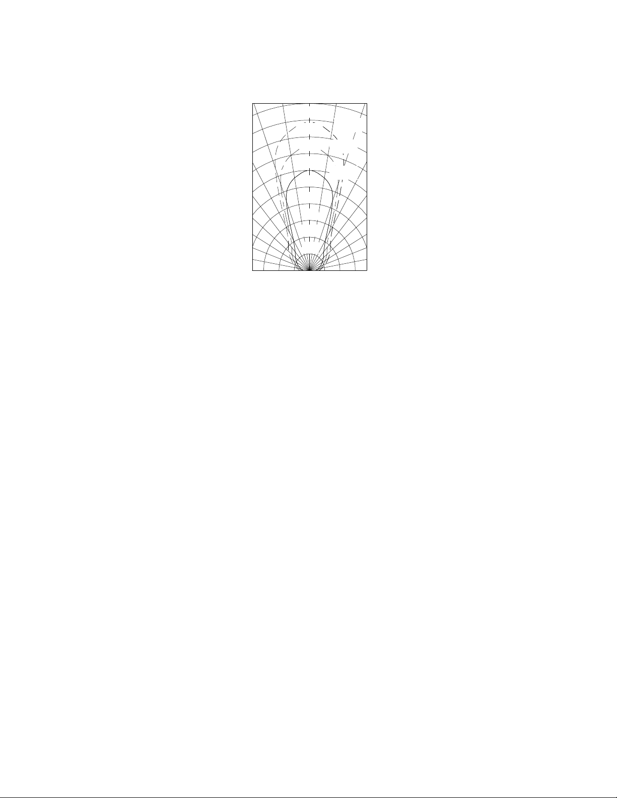
many. The following figure is the radiating pattern of the SA611, SA612, and SA613 emitter
panels. The SA611, SA612, and SA613 cover approximately 3,000 sq. ft., 6,000 sq. ft., and
9,000 sq. ft. respectively. However, the room’s square footage does not necessarily correspond
directly to the emitter coverage. Therefore, the coverage pattern should be laid over a plan of
the space to be designed to make sure every seat is covered. Although the emitters cover a
large area, it is always better to over design with a line of sight system.
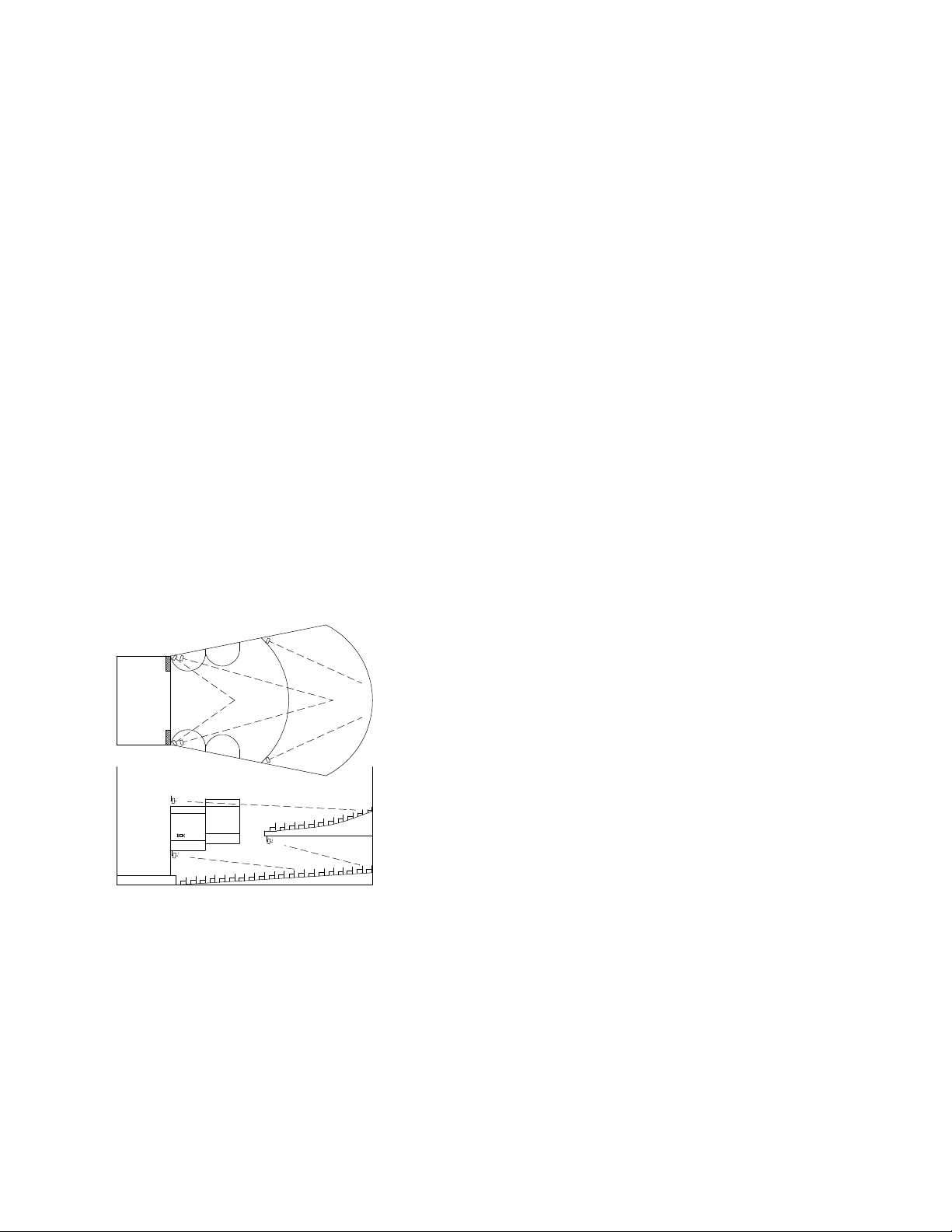
This figure shows the emitter layout for a large theater
with one overhang and approximately 1000 seats. You
will notice the emitter is positioned over the last seat it is
to cover, and faces into the seating area causing a
crisscross of the emitter radiating patterns. The
crisscross configuration of the emitter panels usually
covers the most area per emitter while overlapping
infrared signals. This allows the same seat to be covered
by two or more emitters so a temporary obstruction, such
as a person or scenery (between the receiver and the
emitter), will not alter the reception.
When designing an infrared listening system for any
space the five points that must be considered are: 1) the
room size, 2) the seating rake, 3) obstructions, 4) the wall
- 3 -
Page 5
20
30
40
50
60
70
80
10
180 ft.
160 ft.
140 ft.
120 ft.
100 ft.
80 ft.
60 ft.
40 ft.
20 ft.
10
0
SA-613
SA-612
SA-611
20
30
40
50
60
70
80
Seating Rake
The seating rake relates directly to vertical position of the emitter and emitter coverage. Due to
the system design, the headse t/receiver’s receiving diode (positioned under the users chin)
must be in direct view of the emitter. Therefore, the emitter must be positioned high enough to
clear the head of the person seated in front the last row you wish to cover with that emitter. As
the rake increases, the receiver is more visible, allowing the emitter to cover more seats at a
lower vertical height.
Obstructions
Permanent obstructions such as columns or balconies and temporary obstructions such as
people or scenery are common in most facilities that require an infrared system.
Although the infrared listening device has excellent audio quality and little interference, the
carrier behaves the same as visible light, and can be blocked or shadowed. If a temporary
obstruction passes between the receiver and the emitter (such as a person or scenery), static
may be heard temporarily. This is possible, but unlikely in most situations since the signal is
received in two ways. The first is a direct signal, which means the signal received by the
headset is in a direct path of the transmission from the emitter. The second type of reception is
an indirect signal, which means the signal reaches the receiver by way of reflection. This
reflective property, along with individual design, should insure that no interference will occur with
temporary or permanent obstructions.
Wall and Ceiling Color
The infrared listening system uses infrared light as the carrier of the modulated audio signal.
This light signal is invisible to the naked eye but has the same properties as visibl e light.
Therefore, light-colored surfaces reflect the infrared signal; increase the ind irect reception; and
decrease the size or number of emitters, while dark surfaces absorb the infrared signal.
Extraneous Light
A concentration of infrared light on the receiving diode of the receiver will cause interference
with the carrier frequency and raise the noise floor in the receiver. The infrared system is
inoperable with ambient illumination above 200fc for incandescent lights, 1000fc for daylight,
and 1000fc for fluorescent lights.
- 4 -
Page 6
The Sound Associates Infrared Listening System 600 operates on the industry standard 95 or
250 kHz subcarrier. However, some electronic ballast fluorescent lights cause interference up
to 100 kHz. The interference is attributed to the mercury found in energy-efficient fluorescent
lights which causes broadband interference across the infrared spectrum. Therefore, 95 kHz
cannot be used where energy-efficient fluorescent lights exist. When the use of energy-efficient
lights is unavoidable, the secondary frequency of 250 kHz must be utilized. Sound Associates
offers headsets and transmitters set at 250 kHz to avoid interference with energy-efficient
fluorescent lights.
MOUNTING EMITTER PANEL
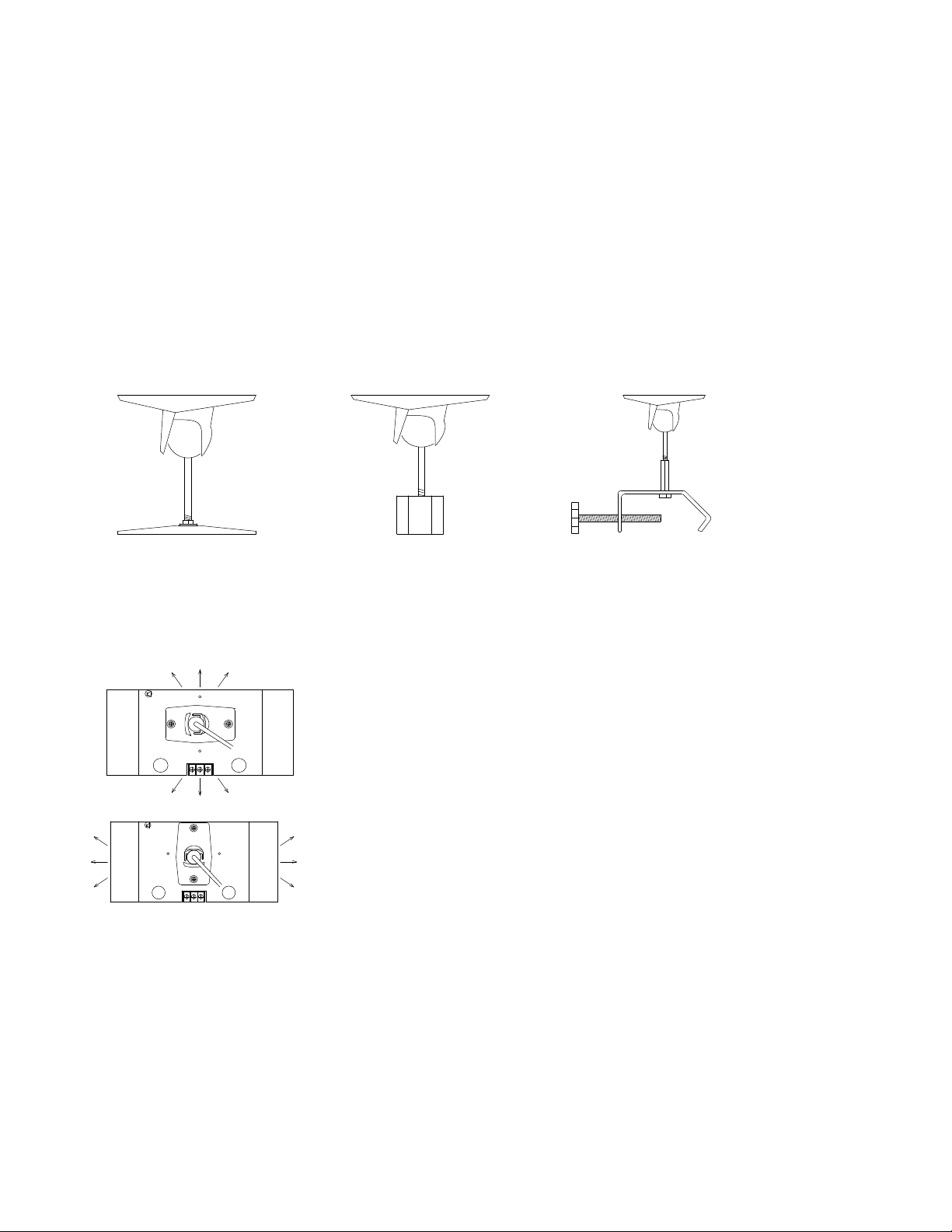
The 600 series emitters utilize 25 series Omnimounts to secure emitters to ceiling, walls,
microphone stands, or piping. Sound Associates offers three types of mounts:
MB1-3
Wall and
Ceiling
Mount
MB1-MA
Mic Stand
Mount
MB1-C
Pipe
Mount
The mount can be separated into two sections by loosening the Allen bolt under the pivot ball.
The socket end of the mount attaches to the emitter and the opposite end to the wall,
microphone stand, or pipe. Each mount attaches to the emitter via two 1/2” 8/32 screws (Note:
The mounting screw can not exceed 1/2” because the screw will damage the PC board).
sound
associates, inc.
MODEL #: SA-611
MADE IN USA
The socket end of the mount can attach to the emitter horizontally to
allow the emitter more mobility in the vertical direction…
5
1
~
3
54V+21
INPUT (M ALE)
3
~
GND
3
4
2
5~V+
1
GND
OUTPUT (FEMALE)
V+
GND
sound
associates, inc.
MODEL #: SA-611
MADE IN USA
or the mount can attach to the emitter vertically, to allow the emitter
more mobility in the horizontal direction.
~
3
54V+21
INPUT (MALE)
3
V+
2
GND
4
~
1
GND
GND
OUTPUT (FEMALE)
5~V+
After deciding on the location of the emitters, fix the mounting plate of the MB13 to a secure flat
surface with two screws or bolts with a maximum diameter of 1/4 inch. To allow for proper
ventilation, the emitter panel should be mounted 12 inches from all walls and ceilings. When
using the mounting bracket with the clamp, be sure not to over-tighten the bolt and use safety
wires where necessary.
CABLING
The 600 series emitter panels are low voltage high output infrared light sources. The emitter is
connected to the emitter power supply via one 2 conductor shielded cable. This single cable
- 5 -
Page 7
~
~
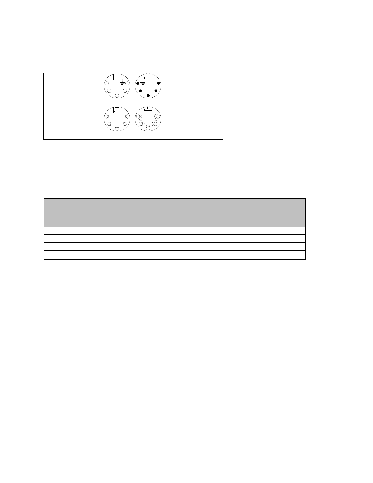
supplies low voltage 17-30 VDC plus the modulated audio signal. The emitter cable pin
configuration is as follows:
Female 5-Pin XLR
Top of Connector
FEMALE 5-PIN XLR
TOP OF CONNECTOR
Female 5-Pin XLR
Bottom of Connector
FEMALE 5-PIN XLR
BOTTOM OF CONNECTOR
+DC +DC
5
24 2 4
3
1
2
4 4 2
3
1
3
5 1
3
5
Male 5-Pin XLR
Top of Connector
MALE 5 -PIN XLR
TOP OF CONNECTOR
Male 5-Pin XLR
Bottom of Connector
MALE 5-PIN XLR
BOTTOM OF CONNECTOR
Pin 1 = Shield = Ground
Pin 2 = Ground
Pin 3 = White / Red = Signal
Pin 4 = Positive DC
Pin 5 = Black = Positive DC
The 600 series emitters are connected to the PS24 via 5-Pin XLR connectors, wire with
enclosed stake-on, or bare wire secured directly to the emitter. Each power supply can power
up to four SA611’s, two SA612’s or one SA613 and one SA611 emitter panel. Emitters can be
“daisy chained” or linked together and up to 50 power supplies can be added to increase
coverage. Refer to the table below to determine the maximum cable length between the power
supply and last emitter.
Alpha Model
#/Gauge
2421 18 AWG 2.4 amps 110 ft. 240 ft.
2432 16 AWG 2.4 amps 190 ft. 400 ft.
2442 14 AWG 2.4 amps 330 ft. 740 ft.
2444 12 AWG 2.4 amps 490 ft. 1000 ft.
Max. Load Maximum Distance from
Power Supply to Las t
Emitter Panel
(24 VDC supply)
Maximum Distance from
Power Supply to Las t
Emitter Panel
(30 VDC supply)
NOTE: The formula to calculate the maximum distance is:
(1/DCR1)+ (1/DCR2) (Vdrop /Load) (1/4)
Where: DCR1 = DC resistance of the 2 conductors.
DCR2 = DC resistance of the drain wire.
Vdrop = Maximum Voltage drop [supply voltage (24 or 30 VDC) - minimum
operating voltage (19 VDC)], in this case is 5 V for the 24 VDC or 11 V for the 30
VDC at power source.
Load = Maximum load on the line, in this case the maximum load at 24 VDC is
2.4 Amps.
NOTE: The two unused pins are linked internally on the PCB of the emitter and power supply to
the ground a nd positive DC respectively. Therefore, the 5-Pin XLR connector pin 2 is linked to
pin 1 (ground) and pin 4 to pin 5 (positive DC).
NOTE: The wiring of the emitter is very important. Most problems with the Infrared System
stem from incorrect wiring. Before powering the system check to mak e sure:
1) No shorts exist between conductors
2) The positive DC is not placed on the ground or signal terminals
- 6 -
Page 8

the photo cell on the headset is in direct view of the
Signal is received but with some static in the
FAILURE / POWER INDICATORS
Each emitter is equipped with a DC power indicator, a signal indicator, and fault LED indicator.
The power/signal indicators are located on the bottom of the emitter panel next to the 5-Pin XLR
connectors. The red LED will light when >19 VDC is present at th e emitter. The red light will
flicker off and the green light will come on when voltage and signal are present.
The 600 series emitter panels also have a fault LED for every 50 diodes. The fault LED is
located on the top right hand side of each set of 50 diodes and will illuminate red if a row of
diodes fail. The fault LED will also indicate voltage irregularities in the voltage regulator. The
emitter panel should be repaired as soon as a failure indicator illuminates.
Note: If the modulation circuit is overloaded, the red power LED on the bottom of the emitter
and the front panel emitter fault LED will flash with each peak. This will occur only after audio
distortion is reached. Simply lower the audio input gain or main front panel gain control if this
occurs on a regular basis.
TROUBLESHOOTING
Symptom Cause/Remedy
Only white noise or static is heard in the
headset
No static and no audio in the headset The headset is not powered or the infrared light is
headset
Headset is not receiving the infrared transmission
Make sure...
...power supply is powered (the red LED on the
emitter panel should light when transmitter is OFF)
...transmitter is powered (the red LED should flicker
out and the green LED on the emitter panel should
light)
...cable is not interrupted or crossed
...
emitter panel
being received with no audio signal “on its back”
Make sure...
...the audio input is plugged into the transmitter and
functioning properly
...the volume on the transmitter is turned up
...the volume on the headset is turned up
...the headset battery is charged and secured firmly
in place
The infrared si gnal is too weak or high levels of
infrared light are interfering with the transmission
Make sure...
...all emitters are connected and being powered
...emitters are in direct sight and not blocked
...emitter fault indicator light is not on
...intense light is not shining on the photo cell on the
receiver
...energy efficient fluorescent lights are not in use
(they cause interference with the 95 kHz subcarrier)
- 7 -
Page 9

Both Green (Signal) and Red (DC Power)
Symptom Cause/Remedy
Red LED DC Power Indicator Light is on
(located on bottom of emitter)
Indicator Lights are on
Red LED (Fault) Indicator Light is on
(located on front of emitter)
DC power is present but no modulated audio signal
is reaching the emitter
Make sure...
...transmitter is on
...connection cable between transmitter and power
supply is complete
...signal wire between power supply and emitter is
complete (pin 3)
Voltage is too low or modulator signal is not
functioning properly
Make sure...
...voltage is greater than 19 VDC at emitter
...modulation conductors are not interrupted
...95/250 kHz sinewave is present at emitter
…Audio signal is not over driving the transmitter
Diode has failed
...Send in for service
SERVICE OR REPAIRS
Contact Sound Associates’ Customer Service Department at 888-772-SOUND (7686) 10:005:30 Monday through Friday for any service or repairs.
- 8 -
Page 10

TECHNICAL SPECIFICATION
Number of Diodes 50 100 150
Average IR Power 1W 2W 3W
Approximate Coverage 3000 sq. ft. 6000 sq. ft. 9000 sq. ft.
IR light wavelength 940 nm 940 nm 940 nm
Modulated AF input 50 mV – 3 V/5 K
Carrier frequency range 30 kHz – 280 kHz 30 kHz – 280 kHz 30 kHz – 280 kHz
Input connection Terminal strip or
Output connection Terminal strip or
Switching thresh old for automati c
on/off function
Supply voltage (nominal) 24 – 30 VDC 24 – 30 VDC 24 – 30 VDC
Minimum Supply voltage 19 VDC 19 VDC 19 VDC
Maximum Supply voltage 30 VDC 30 VDC 30 VDC
Power consumption 0.6 A 1.2 A 1.8 A
Dimensions 7.75”w x 3.75”h x
Weight 1.6 lbs 3.2 lbs. 4.8 lbs
Finish Black or white
Material Aluminum extrusion Aluminum extrusion Aluminum extrusion
SA611 SA612 SA613
50 mV – 3 V/5 K
ohms
male 5-pin XLR
female 5-pin XLR
50 mV 50 mV 50 mV
2.8”d
powder coat
ohms
Terminal strip or
male 5-pin XLR
Terminal strip or
female 5-pin XLR
7.75”w x 7.5”h x
2.8”d
Black or white
powder coat
50 mV – 3 V/5 K
ohms
Terminal strip or
male 5-pin XLR
Terminal strip or
female 5-pin XLR
7.75”w x 11.25”h x
2.8”d
Black or white
powder coat
ACCESSORIES
Mounts: Cable:
• MB13 Wall or ceiling bracket • SA6000 (16 GA emitter cable, bulk/ft.)
• MB1MA Microphone stand mount • SA6000P (16 GA emitter cable, plenum rated,
bulk/ft.) • SA6001 (5-pin XLR line connectors, pair)
• MB1C Emitter mount with clamp • SA6025 (25 ft. cable with 5-pin XLR connectors)
• SA6050 (50 ft. cable with 5-pin XLR connectors)
• SA6100 (100 ft. cable with 5-pin XLR connectors)
*custom cable sizes also available
- 9 -
Page 11

SOUND ASSOCIATES
We, Sound Associates, Inc., warrant to you the o rigina l owner or any
subsequent owner of each new Sound Associates infrared transmitter, emitter
power supply, or emitter panel, that the unit is free of defects in workmanship and
materials for a period of three years from date of original purchase. If the infrared
product fails due to defects in materials or workmanship, or does not meet
specifications enclosed with the product, Sound Associates will repair or replace
the un it, whichever Sound Associates chooses, free of charge. All repairs will be
conducted by trained personnel at Sound Associates’ facility in reasonable time.
All expenses on remedying the defect, including return shipping will be borne by
Sound Associates. All shipping fees, taxes, duties, and other customs fees
incurred by products being shipped between foreign countries will be b orne by
the purchaser.
Sound Associates is not responsible for malfunctions due to misuse,
accident, or neglect. This warranty does not cover damage to other products
resulting from Sound Associates product failure. It does not cover defects or
damage caused by unauthorized modifications or service. Sound Associates
reserves the right to change the design of any product without notice and with no
obligation to make corresponding changes in products previously manufactured.
FULL THREE YEAR WARRANTY
- 10 -
Page 12
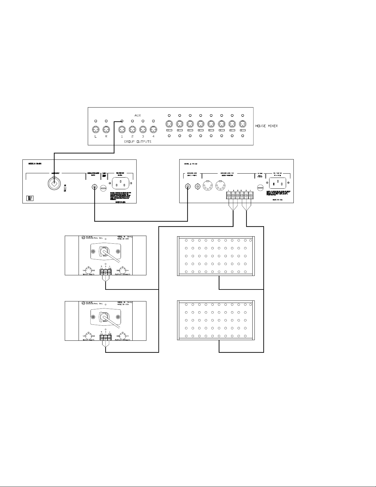
Typical System Schematic
SA-601F
SA-611
¼” phone to ¼” phone or XLR audio
RG 58U BNC to BNC
RG59U for short runs
2 conductor shielded cable
SA-611
PS-24
2 conductor
shielded
cable
page 12
SA-611
SA-611
- 11 -
 Loading...