

Page 1
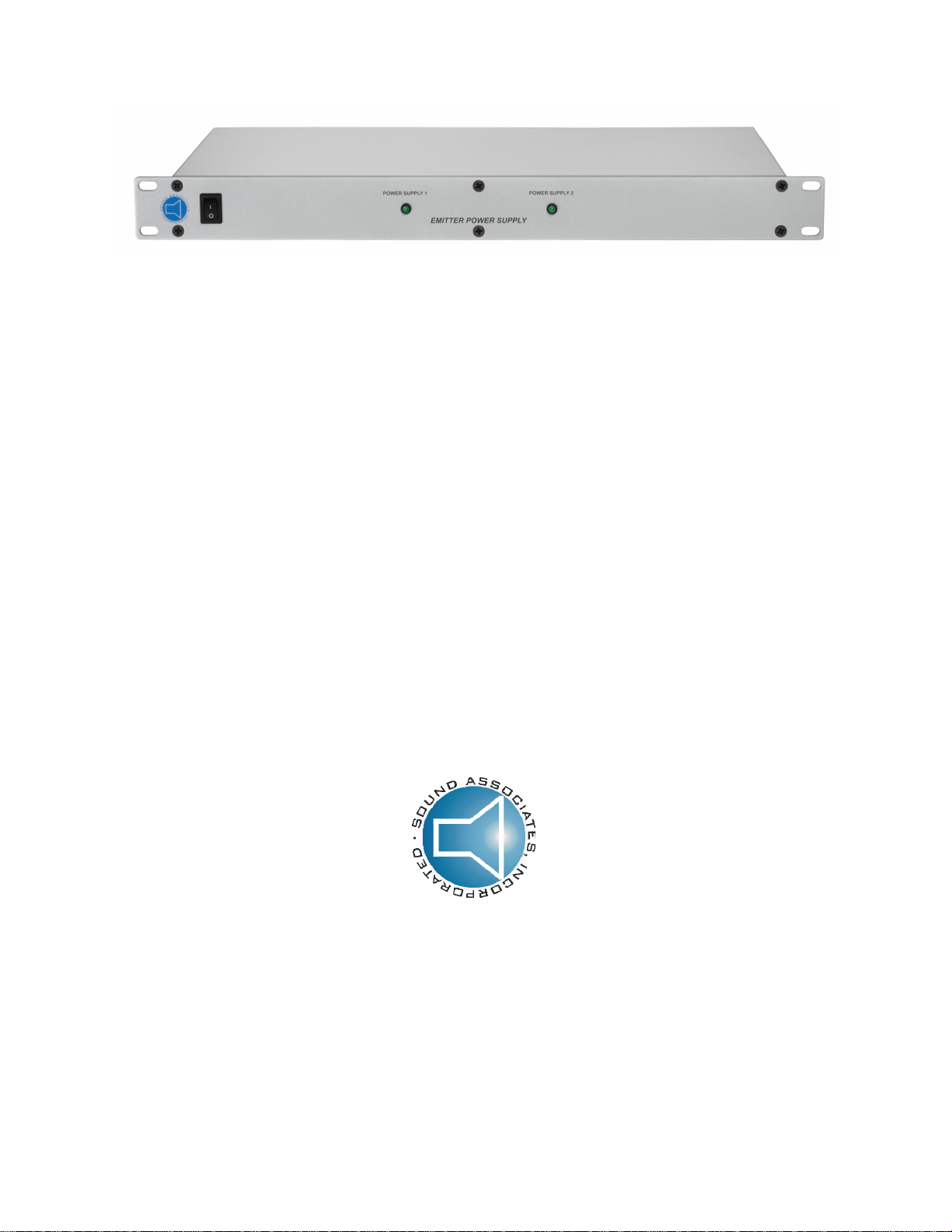
OPERATION MANUAL
SA1710 & SA1720
INFRARED EMITTER POWER SUPPLY
SOUND ASSOCIATES, INC.
424 West 45th Street, New York, NY 10036
Tel: (212)757-5679 Fax: (212)265-1250
Toll free: (888)772-7686
www.soundassociates.com
Page 2

TABLE OF CONTENTS
IMPORTANT SAFETY INFORMATION........................................................................................2
INTRODUCTION...........................................................................................................................3
INFRARED LISTENING SYSTEM FEATURES............................................................................3
UNPACKING UNIT……………………………………………………………………………............ ..4
RACK MOUNTING……………………………………………………………………………............ ..4
FRONT PANEL CONTROLS SA1710……………………………………………………………........4
REAR PANEL CONTROLS SA1710 …………………………………………………………............4
FRONT PANEL CONTROLS SA1720……………………………………………………………........5
REAR PANEL CONTROLS SA1720………………………………………………………….............5
POWER CONNECTION...............................................................................................................6
INPUT/LINK CONNECTION .........................................................................................................7
OUTPUT CONNECTION..............................................................................................................7
CABLING......................................................................................................................................7
TROUBLESHOOTING..................................................................................... ............................9
SERVICE OR REPAIRS...............................................................................................................9
TECHNICAL SPECIFICATIONS............................................................................................... .10
ACCESSORIES.........................................................................................................................10
WARRANTY...............................................................................................................................11
TYPICAL SYSTEM SCHEMATIC...............................................................................................12
Page 3
IMPORTANT SAFETY INFORMATION
CAUTION: TO REDUCE THE RISK OF ELECTRIC SHOCK,
DO NOT REMOVE COVER (OR BACK).
NO USER-SERVICEABLE PARTS INSIDE.
REFER SERVICING TO QUALIFIED SERVICE PERSONNEL.
DO NOT EXPOSE TO RAIN OR MOISTURE.
The lightning flash with arrowhead symbol within an equilateral triangle is intended to alert the user to the presence
of un-insulated "dangerous voltage" within the product's enclosure. It may be of sufficient magnitude to constitute a
risk of electric shock to persons.
The exclamation point within an equilateral triangle is intended to alert the user to the presence of important
operating and maintenance (servicing) instructions in the literature accompanying the product.
Warnings
• Connect this unit’s power cord only to an AC outlet of the type stated in this Owner’s Manual or as marked on the
unit. Failure to do so is a fire and electrical shock hazard.
• Do not allow water to enter this unit or allow the unit to become wet. Fire or electrical shock may result.
• Do not place a container with liquid or small metal objects on top of this unit. Liquid or metal objects inside this
unit are a fire and electrical shock hazard.
• Do not remove the unit’s cover. You could receive an electrical shock. If you think internal inspection,
maintenance, or repair is necessary, contact your dealer.
• Do not modify the unit. Doing so is a fire and electrical shock hazard.
• If the power cord is damaged (i.e., cut or a bare wire is exposed), ask your dealer for a replacement. Using the
unit with a damaged power cord is a fire and electrical shock hazard.
• If you notice any abnormality, such as smoke, odor, or noise, or if a foreign object or liquid gets inside the unit,
turn it off immediately. Remove the power cord from the AC outlet. Consult your dealer for repair. Using the unit
in this condition is a fire and electrical shock hazard.
Cautions
• Keep this unit away from the following locations:
Locations exposed to oil splashes or steam.
Unstable surfaces, such as a wobbly table or slope.
Do not install near any heat sources such as radiators, heat registers, stoves, or other apparatus
(including amplifiers) that produce large quantities of heat.
Locations subject to excessive humidity or dust accumulation.
• Hold the power cord plug when disconnecting it from an AC outlet. Never pull the cord. A damaged power cord is
a potential fire and electrical shock hazard.
• Do not touch the power plug with wet hands. Doing so is a potential electrical shock hazard.
• This unit is equipped with a dedicated ground connection to prevent electrical shock. Before connecting the
power plug to an AC outlet, be sure to ground the unit.
• To relocate the unit, turn the power switch off, remove the power plug from the AC outlet, and remove all
connecting cables. Damaged cables may cause fire or electrical shock.
- 2 -
Page 4
INTRODUCTION
The Sound Associates Infrared Listening System is a wireless assistive listening device which may be
used as an aid for the hard of hearing, sight description, or simultaneous translation. As an assistive
listening device, the Infrared Listening System meets the Americans with Disabilities Act standards to aid
the hearing impaired. Also, infrared technology meets international standards for wireless interpretation
equipment. The Sound Associates Infrared system consists of three major components: the transmitter,
the emitter, and the receiver.
The Sound Associates SA1710 and SA1720 are low voltage infrared emitter power supplies for new and
existing infrared emitter panels. The SA1710 utilizes a regulated switching 30 volt DC power supply that
can power up to six Sound Associates SA611, three SA612, or two SA613 emitter panels. The SA1720
houses two regulated supplies that can power up to twelve Sound Associates SA611, six SA612, or 4
SA613 emitter panels. These emitter power supplies combine low voltage with a modulated audio signal
supplied by an infrared transmitter. The emitter and power supply are connected via a single two
conductor - shielded cable or a 50Ω coax plus 2 conductor cable terminated at the power supply with
either a 5 pin XLR connector or bare wire. This single cable supplies a modulated audio signal and
power to the emitter, eliminating the need for an electrical outlet at each emitter location.
The following instructions should be read completely before attempting to install any equipment to ensure
proper set up and use of the system. If you require further assistance, please call our Customer Service
Department Monday-Friday 9:30 am – 5:30 pm EST at (888) 772-SOUND (7686).
INFRARED LISTENING SYSTEM FEATURES
Infrared Technology
Feature Advantage
Wireless receivers No pre-registered seating
No “deaf section”
Easy distribution
Wireless signal transmission by Infrared light as
compared to RF transmission
The audio signal is frequency modulated at 95 kHz,
250 kHz, 2.3 MHz, or 2.8 MHz
Emitter Power Supply: SA1710 and SA1720
Feature Advantage
Worldwide AC input - Automatic Sensing Capable of operating on either 115 VAC at 60 Hz, or 230 VAC
Power Supply can be linked with existing infrared
transmitters via BNC connection
1u chassis design Allows power supply to mount in one rack space in standard
Low voltage emitters powered by SA1710 or SA1720 Eliminates the need for electrical outlets at each emitter
Full three-year warranty Insures years of trouble free use
Confidentiality; signal will not pass through walls or
curtains
No interference from common radio signals
Superior audio quality
Industry standard
Headsets are interchangeable with other home and
large area systems
at 50 Hz. Automatically senses input voltage
Can be used with Sound Associates or other manufacturers’
transmitters/base stations
19” rack
location
- 3 -
Page 5

UNPACKING UNIT
As soon as the shipment is received, inspect the unit and all components for damage incurred by
shipping. Also, check to see if all components are enclosed.
Equipment enclosed:
1 SA1710 or SA1720 Infrared Emitter Power Supply
1 BNC003 3ft RG59u BNC to BNC cable
1 AC power cord
1 Instruction manual
If the unit is damaged due to shipping, please keep all packing material and contact the shipping
company as soon as possible. Only the consignee may institute a claim against a carrier if damage has
occurred in shipping; however, Sound Associates will assist in any such event.
RACK MOUNTING
The SA1710 and SA1720 will rack mount in a standard 19” rack. The unit will mount in one rack space
(1u). When racked with other equipment, be sure to separate by one rack space for proper ventilation.
FRONT PANEL CONTROLS – SA1710
1 - Power Switch: Applies line power. “I” position is power on and “O” position is power off.
2 - Power supply indicator: Lights “on” when power supply is outputting >24 VDC.
REAR PANEL CONTROLS – SA-1710
- 4 -
Page 6
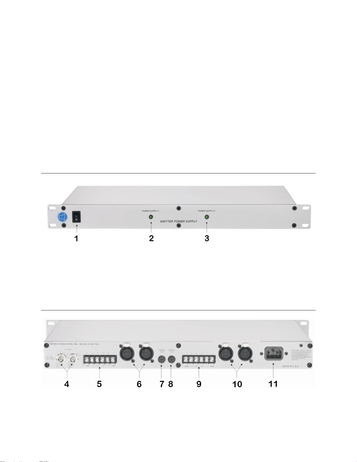
3 – Modulated Audio Input/Output: BNC connection allows input to receive modulated audio signal
from infrared transmitter and output to link to additional power supplies via RG58u cable (RG59u can be
used cable for short runs). Input and output are independent of power source.
4 – Terminal Block Modulated Audio / DC: Connection to emitters via “stake-on” or bare wire, supplies
low voltage plus modulated audio (same as 5-pin XLR). (Pin 1: Shield = Ground); (Pin 3: White / Red =
Signal); (Pin 5: Black = Positive DC).
5 – 5-pin XLR modulated output / DC: Connection to emitters via 5-pin XLR, supplies low voltage plus
modulated audio signal. (Pin 1: Shield = Ground); (Pin 2: Ground); (Pin 3: White / Red = Signal); (Pin 4:
Positive DC); (Pin 5: Black = Positive DC). (Note: Pin 1 is tied to Pin 2 and Pin 4 is tied to Pin 5 in the
power supply and emitter.)
6 – DC Fuse: Prevents excessive current flow on DC output. Timed 5A 5x20 mm fuse.
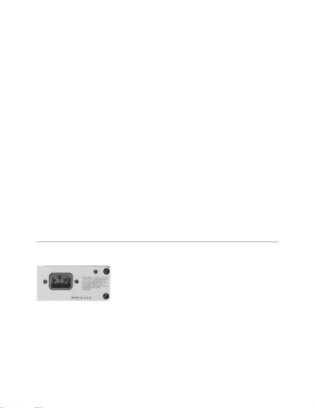
7 – AC Power In Connector: Connector enables user to connect the SA1710 or SA1720 to an AC outlet
via the supplied 10A IEC power cord.
FRONT PANEL CONTROLS – SA1720
1 - Power Switch: Applies line power. “I” position is power on and “O” position is power off.
2 - Power supply indicator #1: Lights “on” when power supply #1 is outputting >24 VDC.
3 – Power supply indicator #2: Lights “on” when power supply #2 is outputting > 24 VDC.
REAR PANEL CONTROLS – SA-1720
- 5 -
Page 7
4 – Modulated Audio Input/Output: BNC connection allows input to receive modulated audio signal
from infrared transmitter and output to link to additional power supplies via RG58u cable (RG59u can be
used cable for short runs). Input and output are independent of power source.
5 – Terminal Block Modulated Audio / DC: Connection to emitters via “stake-on” or bare wire, supplies
low voltage plus modulated audio (same as 5-pin XLR). (Pin 1: Shield = Ground); (Pin 3: White / Red =
Signal); (Pin 5: Black = Positive DC). Associated with power supply #1.
6 – 5-pin XLR modulated output / DC: Connection to emitters via 5-pin XLR, supplies low voltage plus
modulated audio signal. (Pin 1: Shield = Ground); (Pin 2: Ground); (Pin 3: White / Red = Signal); (Pin 4:
Positive DC); (Pin 5: Black = Positive DC). (Note: Pin 1 is tied to Pin 2 and Pin 4 is tied to Pin 5 in the
power supply and emitter.) Associated with power supply #1.
7 – DC Fuse Power Supply #1: Prevents excessive current flow on DC output. Timed 5A 5x20 mm
fuse.
8 – DC Fuse Power Supply #2: Prevents excessive current flow on DC output. Timed 5A 5x20 mm
fuse.
9 – Terminal Block Modulated Audio / DC: Connection to emitters via “stake-on” or bare wire, supplies
low voltage plus modulated audio (same as 5-pin XLR). (Pin 1: Shield = Ground); (Pin 3: White / Red =
Signal); (Pin 5: Black = Positive DC). Associated with power supply #2.
10 – 5-pin XLR modulated output / DC: Connection to emitters via 5-pin XLR, supplies low voltage plus
modulated audio signal. (Pin 1: Shield = Ground); (Pin 2: Ground); (Pin 3: White / Red = Signal); (Pin 4:
Positive DC); (Pin 5: Black = Positive DC). (Note: Pin 1 is tied to Pin 2 and Pin 4 is tied to Pin 5 in the
power supply and emitter.) Associated with power supply #2.
11 – AC Power In Connector: Connector enables user to connect the SA1710 or SA1720 to an AC
outlet via the supplied 10A IEC power cord.
POWER CONNECTION
The transmitter is furnished with a detachable AC power cord rated for 10 A at 120 volts that plugs into a
15 A plug.
The SA1710 and SA1720 are equipped with internal power supplies that will accept an input voltage of
115 VAC or 230 VAC. Due to this auto sensing power input there is no need to manually switch the
supply if utilizing a higher input voltage.
At 115 VAC, the Mains fuse, located internally on the main PCB, must be a T2.0 A fuse (normally ships
with this fuse). With an input voltage of 230 VAC, the Mains fuse should be a T1.0 A fuse. Voltages over
264 volts are potentially damaging to the SA1710 and SA1720 power supply circuit.
- 6 -
Page 8
INPUT/LINK CONNECTION
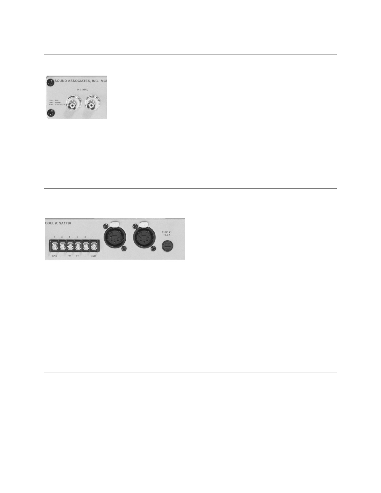
The input / link section consists of two BNC connections.
The input signal should be a modulated audio signal from an infrared transmitter or base station >55 kHz
with a nominal peak to peak voltage of 2 - 8V. The connection is made via an RG58u (RG59u for short
runs) cable terminated with a BNC connector. The modulated audio input and output (link) are
independent of the power source. Therefore, if power to the SA1710 or SA1720 is cut, other power
supplies in the chain will not be affected.
OUTPUT CONNECTION
The output section for each internal power supply consists of one 6 – position terminal bar and two 5-pin
XLR connectors.
The SA1710 and SA1720 supply low voltage and modulated audio signal to Sound Associates emitter
panels. The power supply is set to 30 VDC output, but can be adjusted from 27.0 VDC to 33.0 VDC +/-
0.5 VDC. The adjustment is made internally on the internal power supply at the pot marked “VR1.” Each
SA1710 can power up to 300 diodes, which includes one of the following combinations: six SA611’s,
three SA612’s, or two SA613’s. The SA1720 can power up twelve SA611’s, six SA612’s, or four SA613’s
or any combination of diodes up to 600. The modulated audio output plus DC voltage connects to the
emitter panel via a 2-co nductor shielded cable terminated with a 5-pin XLR connector or bare wire. The
5-pin XLR connector is used mainly when plugging and unplugging the emitter cable is necessary, such
as quick installations, portable systems, or rental systems. The terminal block supplies the same signal
as the 5-pin XLR connector but is used in more permanent installations where the emitter connection will
not be removed on a constant basis.
CABLING
The emitter is connected to the emitter power supply, in most cases, via one 2 conductor shielded cable.
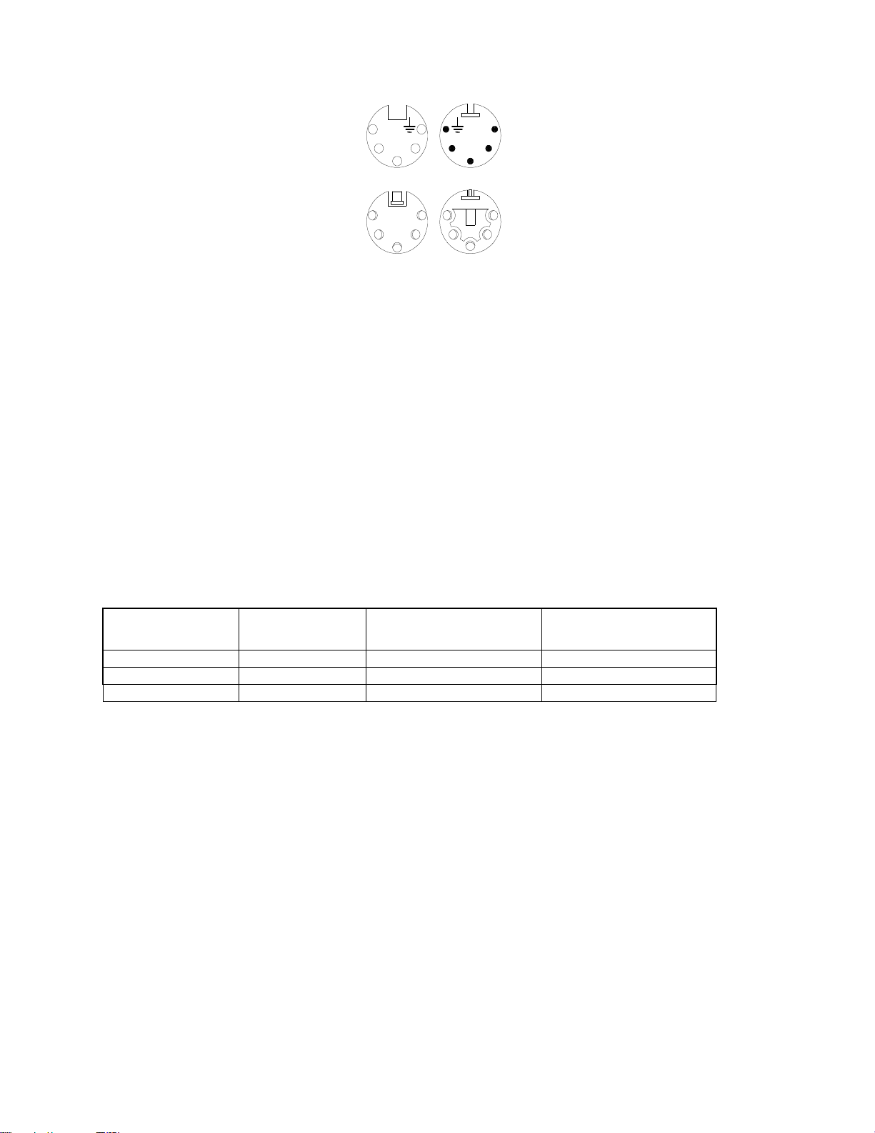
This single cable supplies low voltage 17-30 VDC plus the modulated audio signal. The emitter cable pin
configurations are as follows:
- 7 -
Page 9
3
1 2 4 2 4
5
1
2 3 4 4 2 3
5 1
~
~
FEMALE 5-PIN XLR
TOP OF CO NNECTOR
+DC
5
+DC
3
MALE 5-PIN XLR
TOP OF CO NNECTOR
FEMALE 5-PIN XLR
BOTTOM OF CONNECTOR
MALE 5-PIN XLR
BOTTOM OF CONNECTOR
Pin 1: Shield = Ground
Pin 2: Ground
Pin 3: White / Red = Signal
Pin 4: Positive DC
Pin 5: Black = Positive DC
The Sound Associates emitters are connected to the SA1710 and/or SA1720 via 5-Pin XLR connectors or
bare wire. Emitters can be “daisy chained” or linked together for a maximum of 300 diodes per power
supply. Also, additional SA1710 and SA1720 power supplies can be added to increase the number of
emitter panels and ultimately, the coverage. Refer to the table below to determine the maximum cable
length between the power supply and last emitter.
For cable runs that exceed 300ft it may be necessary to utilize 50Ω coaxial cable for the signal conductor.
The higher frequencies need a clean signal at the emitter requiring the longer cable runs to be made via
coax cable. In this case it is recommended that the terminal bar be utilized with the coax center
connected to Pin 3 (signal) and the coax shield to Pin 1 (ground).
NOTE: The formula to calculate the maximum distance is:
(1/”DCR1”)+ (1/”DCR2”) (“Vdrop” /”Load”) (1/4)
Alpha Model #/Gauge Max. Load Maximum Distance from Power
Supply to Last Emitter Panel
(24 VDC supply)
20 AWG 2.4 amps 140 ft. 250 ft.
2421 18 AWG 2.4 amps 150 ft. 280 ft.
2432 16 AWG 2.4 amps 200 ft. 350 ft.
Maximum Distance from Power
Supply to Last Emitter Panel
(30 VDC supply)
Where: DCR1 = DC resistance of the 2 conductors.
DCR2 = DC resistance of the drain wire.
Vdrop = Maximum Voltage drop [supply voltage (24 or 30 VDC) - minimum operating voltage (17 VDC)], in this case
is 7 V for the 24 VDC or 13 V for the 30 VDC at power source.
Load = Maximum load on the line, in this case the maximum load at 24 VDC is 2.4 Amps.
NOTE: The two unused pins on the 5-Pin XLR are linked internally on the PCB of the emitter and power supply to the ground and
positive DC respectively. Therefore, in the 5-Pin XLR connector pin 2 is linked to pin 1 (ground) and pin 4 to pin 5 (positive DC).
NOTE: The wiring of the emitter is very important. Most problems with the infrared system stem from incorrect wiring. Before
powering the system, check to make sure: 1) no crosses exist between conductors and 2) the positive DC is not placed on the
ground or signal terminals.
- 8 -
Page 10

TROUBLESHOOTING
Symptom Cause/Remedy
Only white noise or static is heard in the headset Headset is not receiving the infrared transmission
No static and no audio in the headset The headset is not powered or the infrared light is being received
Signal is received but with some static in the headset The infrared signal is too weak or high levels of infrared light are
Both Green (Signal) and Red (DC Power) Indicator Lights
are illuminated on the emitter panel
Make sure...
...power supply is powered (The red LED on the emitter panel
should light when transmitter is off)
...transmitter is powered (The red LED should flicker out and the
green LED on the emitter panel should light)
...cable is not interrupted or crossed
...the photo cell on the headset is in direct view of the emitter
panel
with no audio
Make sure...
...the audio input is plugged into the transmitter and functioning
properly
...the volume on the transmitter is turned up and showing audio
indication on the VU meter on the main screen.
...the volume on the headset is turned up
...the headset battery is charged and secured firmly in place
interfering with the transmission
Make sure...
...all emitters are connected and being powered
...emitters are in direct sight and not blocked
...emitter fault indicator light is not on
...intense light is not shining on the photo cell on the receiver
...energy efficient fluorescent lights are not in use (they cause
interference with the 95 kHz subcarrier)
Voltage is too low or modulator signal is greater than 8 V P-P.
Make sure...
…Audio Source is not overdriving the transmitter (transmitter in
constant overload).
...voltage is greater than 17 VDC at emitter
...signal conductors are not interrupted
…signal cable length does not exceed 300 ft.
SERVICE OR REPAIRS
Contact Sound Associates’ Customer Service Department at 888-772-SOUND (7686) 9:30 am - 5:30 pm
EST Monday through Friday for any service or repairs.
- 9 -
Page 11

TECHNICAL SPECIFICATION
SA1710 (powers up to 6 SA611 emitters)
MODULATED AUDIO INPUT / LINK
Connector Chassis mount BNC
Number of inputs/outputs (links) 2
OUTPUT
Connector 5-pin female XLR / terminal strip
Number of outputs (2) 5-pin female XLR/ (1) terminal strips
Wiring of 5-pin XLR 1, 2 - ground; 3 - signal; 4, 5 - positive DC
Wiring of terminal strip 1 - ground; 3 - signal; 5 - positive DC
Output voltage 30 +/- 0.5 VDC Internally adjustable
Load regulation + /- 3% typical
Output ripple / noise pk-pk 1% maximum at full load
Efficiency @ full load 80% typical, 70% minimum
Short circuit and current protection Automatic current limit/foldback 150% max
Over voltage protection Automatic 132% maximum
Fuse T5 A (5 x 20) located on back panel
POWER
Power Input Universal input 90 – 264 VAC sensing
Power Input Frequency 47 – 63 Hz auto sensing
Power consumption with (6) SA611 emitters < 120 W
Fuse T2.0 A (5 x 20 mm) @ 120V
T1.0 A (5 x 20 mm) @ 240 V internal
MECHANICAL
Mechanical dimensions 19” w x 1.75” h x 9” d (1U)
Weight 4.2 lbs.
Finish/material Silver powder coat
SA1720 (powers up to 12 SA611 emitters)
MODULATED AUDIO INPUT / LINK
Connector Chassis mount BNC
Number of inputs/outputs (links) 2
OUTPUT
Connector 5-pin female XLR / terminal strip
Number of outputs (4) 5-pin female XLR/ (2) terminal strips
Wiring of 5-pin XLR 1, 2 - ground; 3 - signal; 4, 5 - positive DC
Wiring of terminal strip 1 - ground; 3 - signal; 5 - positive DC
Output voltage 30 +/- 0.5 VDC Internally adjustable
Load regulation + /- 3% typical
Output ripple / noise pk-pk 1% maximum at full load
Efficiency @ full load 80% typical, 70% minimum
Short circuit and current protection Automatic current limit/foldback 150% max
Over voltage protection Automatic 132% maximum
Fuse T5 A (5 x 20) located on back panel x 2
POWER
Power Input Universal input 90 – 264 VAC sensing
Power Input Frequency 47 – 63 Hz auto sensing
Power consumption with (12) SA611 emitters < 240 W
Fuse T4.0 A (5 x 20 mm) @ 120V
T2.0 A (5 x 20 mm) @ 240 V internal
MECHANICAL
Mechanical dimensions 19” w x 1.75” h x 9” d (1U)
Weight 5.1 lbs.
Finish/material Silver powder coat
ACCESSORIES
· BNC003 - RG59u BNC to BNC cable (3ft)
· SA1791LD – Modulated Audio Line Driver – In line amplifier used to drive modulated audio signal for long cable runs.
- 10 -
Page 12

SOUND ASSOCIATES
We, Sound Associates, Inc., warrant to you the original owner or any
subsequent owner of each new Sound Associates infrared transmitter, emitter
power supply, or emitter panel, that the unit is free of defects in workmanship and
materials for a period of three years from date of original purchase. If the infrared
product fails due to defects in materials or workmanship, or does not meet
specifications enclosed with the product, Sound Associates will repair or replace
the un it, whichever Sound Associates chooses, free of charge. All repairs will be
conducted by trained personnel at Sound Associates’ facility in reasonable time.
All expenses on remedying the defect, including return shipping will be borne by
Sound Associates. All shipping fees, taxes, duties, and other customs fees
incurred by products being shipped between foreign countries will be borne by
the purchaser.
Sound Associates is no t responsible for malfunctions d ue to misuse,
accident, or neglect. This warranty does not cover damage to other products
resulti ng from Sound Associates product failure. It does not cover defects or
damage caused by unauthorized modifications or service. Sound Associates
reserves the right to change the design of any product without notice and with no
obligation to make corresponding changes in products previously manufactured.
FULL THREE YEAR WARRANTY
- 11 -
Page 13
TYPICAL SYSTEM SCHEMATIC
1/4" PHONE TO 1/4" PHONE OR
1/4" PHONE TO MXLR AUDIO CABLE
MODEL #: SA1422
TRS - LINE INPUT
XLR - MIC. INPUT
PIN 1 - SLEEVE: GND
PIN 2 - TIP: POSITIVE
PIN 3 - RING: NEGITIVE
1
RG 58u BNC TO BNC CABLE
RG59u FOR SHORT RUNS
SOUND ASSOCIATES, INC. MODEL #: SA1710
IN / THRU
PIN 1 - GND
PIN 3 - SIGN AL
PIN 5 - POSI TIVE DC
PREAMP GAIN
31 5 5 3 1
~GND V+ V+ ~ GND
STEREO OUT
2
PREAMP GAIN
DATA PORT
FUSE #1
AUX SEND
GROUP OUT
REC OUT 2TR IN RE TURN 2 RETURN 1
HOUSE MIXER
MODULATED AUDIO OUTPUTLINK
ON
FUSEPHANTOM
30 VDC
T500 mA
OFF
CAUTION: TO REDUC E THE RISK OF
FIRE OR ELECTRICAL SHOCK DO NOT
EXPOSE THIS EQUIPMENT TO RAIN OR
EXTREME MOISTURE. DO NOT
REMOVE COVER NO USER
SERVICEABLE PARTS INSIDE. REFER
SERVICING TO QUALIFIED
PERSONNEL.
MADE IN U.S.A.
SA1422 INFRARED TRANSMITTER
T5.0 A
CAUTION: TO REDUCE THE RISK
OF FIRE OR ELECTRICAL SHOCK DO
NOT EXPOSE THIS EQUIPMENT TO
RAIN OR EXTREME MOISTURE. DO
NOT REMOVE COVER NO USER
SERVICEABLE PARTS INSIDE. REFER
SERVICING TO QUALIFIED
PERSONNEL.
MADE IN U.S.A.
SA1710 EMITTER POWER SUPPLY
2 CONDUCTOR SHIELDED CABLE
16 GAUGE OR BETTER.
SA611 EMITTER PANEL
SA611 EMITTER PANEL
- 12 -
 Loading...