

Page 1

Preamplifier
Preamplifier 720
Preamplifier Preamplifier
User manual
User manual
User manualUser manual
720
720720
soulution
nature of sound
Page 2

Page 3

Preamplifier
Preamplifier 720
PreamplifierPreamplifier
User Manual
Dear client
Dear client
Dear clientDear client
We are proud that you decided yourself for a soulution preamplifier. You have acquired a preamplifier with outstanding sonic performance which you will enjoy for
many years.
We understand your eagerness to get started but even though please study this
manual step by step before you integrate the preamplifier 720 in your High Fidelity
system. This manual contains also useful tips for the optimisation of your overall
HiFi-system.
720
720720
If there are any questions regarding the start-up or operation of your preamplifier
720 please do not hesitate to contact your dealer.
Have fun!
Have fun!
Have fun!Have fun!
Your soulution team
Your soulution team
Your soulution teamYour soulution team
Page 1
Page 4

soulution
nature of sound
CE
CE----Declaration of Conformity
Declaration of Conformity
CECE
Declaration of ConformityDeclaration of Conformity
Spemot AG declares that this product is in conformance with the following directives and standards:
Low Voltage Directive 2006/95/EG (EN/IEC 60065:2002)
Electromagnetic Compatibility 2004/108/EG (EN 55013:2001, EN 55020:2002,
EN 61000-3-2:2006, EN61000-3-3:1995)
FCC
FCC----Notice
Notice
FCCFCC
NoticeNotice
Note: This equipment has been tested and found to comply with the limits for a
Class B digital device, pursuant to Part 15 of the FCC Rules. These limits are designed to provide reasonable protection against harmful interference in a residential
installation. This equipment generates, uses and can radiate radio frequency energy
and, if not installed and used in accordance with the instructions, may cause harmful interference to radio communications. However there is no guarantee that interference will not occur in a particular installation.
If this equipment does cause harmful interference to radio or television reception,
which can be determined by turning the equipment off and on, the user is encouraged to try to correct the interference by one or more of the following measures:
-
adjust or relocate the receiving antenna
-
increase the separation between the equipment and the receiver
-
connect the equipment into a mains outlet on a circuit different from that to
which the receiver is connected
-
consult the dealer or an experienced radio/TV technician for help
Disposal
Disposal
DisposalDisposal
According to the Directive 2002/96/EG of the European Parliament used
consumer-electro technical appliances have to be disposed separately
and have to be indicated with the following symbol.
In the case of disposal of this component please do so in conformity with legal and
environmental regulations.
Seite 2
Page 5

Preamplifier
User Manual
Table of contents
Table of contents
Table of contentsTable of contents
1
2
3
3.1
3.2
3.3
3.4
3.5
3.6
3.7
3.8
4
4.1
4.2
4.3
4.4
Quick start.......................................................................................... 5
Important security advices: ..................................................................6
Technical Highlights............................................................................ 8
Layout ................................................................................................ 8
Volume control....................................................................................8
Phono-Stage (moving coil) ................................................................... 8
Output stage ....................................................................................... 9
Power supply ...................................................................................... 9
Gain-adjustment ...............................................................................10
DC-PROTECT .................................................................................... 10
Bandwidth limitation ......................................................................... 10
Start of operation and handling of the preamplifier 720 .......................11
Scope of delivery and packing ............................................................ 11
Optimal positioning of your preamplifier 720 ...................................... 11
Rear panel of the preamplifier 720 ..................................................... 12
Front panel of the preamplifier 720 .................................................... 16
Preamplifier 720
PreamplifierPreamplifier
720
720720
5
5.1
5.2
6
6.1
6.2
7
8
8.1
9
9.1
9.2
9.3
10
11
12
13
14
15
Programming of the preamplifier 720 ................................................. 22
Overview........................................................................................... 22
Program-Functions ............................................................................23
Remote control ................................................................................. 33
Start of operation and maintenance .................................................... 33
Handling .......................................................................................... 33
Protection functions of the preamplifier 720 .......................................37
Trouble shooting ............................................................................... 38
Actions after the appearance of an error.............................................. 38
Care and maintenance ....................................................................... 39
Burn-in............................................................................................. 39
Longlife-precautions ..........................................................................39
Cleaning ...........................................................................................39
Service ............................................................................................. 40
Warranty........................................................................................... 40
Specifications ...................................................................................41
Dimensions....................................................................................... 42
Definitions........................................................................................ 43
Individual Settings ............................................................................ 44
Page 3
Page 6

Page 7

Preamplifier
0 and store the packing for future
has a top
system from
the mains supply. Connect your preamplifier 720 with your
. Use
system.
plifier 720 and all other components of
ply. Please use the enclosed
While manipulating with cables
the preamplifier 720 has to remain disconnected from the
Default values for all functions are programmed. No additional
We suggest programming of the
should be
720. Turn
720 to a minimal level.
fier
Preamplifier 720
PreamplifierPreamplifier
User Manual
720
720720
1111 Quick start
Quick start
Quick startQuick start
Unpacking
Unpacking
UnpackingUnpacking
Positioning
Positioning
PositioningPositioning
Cabling
Cabling
CablingCabling
Unpack the preamplifier 72
transportations.
Security advice: Your preamplifier 720
class surface. Please take care during installation.
Position the preamplifier 720 on a stable base.
Security advice: Cooling air must be able to circulate and escape unrestricted.
Disconnect all electrical appliances of your HiFi-
amplifier and signal sources (according to user manual)
the respective signal cables and the cable for the LINKReconnect the pream
your HiFi-system with mains sup
high class mains cable for your preamplifier 720.
Programming
Programming
ProgrammingProgramming
Switch on
Switch on
Switch onSwitch on
Security advice:
mains supply.
programming is required for the start-up of your preamplifier.
Security advice:
functions Start-Volume and Max-Volume. If you use recording equipment the function Record-Loop
programmed as well.
Switch on your source devices and the preamplifier
down the volume of the preamplifier
Switch on your amplifier.
Security advice: Before you switch on the ampli
check whether the cabling is done correctly.
Page 5
Page 8

soulution
nature of sound
2222 Important security advices
Important security advices::::
Important security advicesImportant security advices
User manual
User manual::::
User manualUser manual
Read this user manual carefully before you start-up your preamplifier 720 and follow all installation and security advices.
Please keep this user manual. In the case this manual gets lost you have the possibility to download it from the soulution-webpage.
(http://www.soulution-audio.com/downloads)
Mains supply
Mains supply ::::
Mains supplyMains supply
Exclusively use 3 phase power cords with ground conductor. They may not be
crushed by objects.
Unplug your preamplifier 720 from the mains connection in the following cases:
-
before you manipulate with cables
-
before cleaning
-
during thunder storms or
-
before you leave for longer periods
Cabling
Cabling::::
CablingCabling
While manipulating with cables the preamplifier 720 has to remain disconnected
from the mains. Before you disconnect the mains the preamplifier 720 has to be in
operating condition OFF. Wrong cabling may cause damages to your preamplifier
720, your amplifier or to your loudspeakers. Excessive volumes due to inappropriate
handling may cause hearing damages.
Transport:
Transport:
Transport:Transport:
Use only with the cart, stand, tripod, bracket or table specified by the manufacturer
or sold with the apparatus. When a cart is used, use caution when moving
cart/apparatus combination to avoid injury or tip over.
Seite 6
Page 9

Preamplifier
Preamplifier 720
PreamplifierPreamplifier
User Manual
Packing:
Packing:
Packing:Packing:
Please keep the original packing for future transports. The original packing is optimal protection against potential damages.
Operation:
Operation:
Operation:Operation:
Never run your preamplifier 720
-
with opened housing
-
with closed cooling-slots
-
with high ambient temperatures (>40°C)
-
close to heat sources like radiators, heatings, ovens or similar appliances dissipating heat
-
with extremely high humidity for example in humid cellars or rooms similar
humidity
-
close to water (Sink, bathtub, or similar equipment) or with any object containing water residing on top of the product
720
720720
Cleaning:
Cleaning:
Cleaning:Cleaning:
Use a soft and dry towel. We suggest using a non abrasive micro fibre towel. Please
do not use any solvents or liquidities.
Service:
Service:
Service:Service:
Do not try to repair your preamplifier 720 by yourself. It needs a service check by a
qualified person in the following cases:
-
the mains-cable or the mains connectors are damaged
-
foreign substances or liquidity has entered the preamplifier 720
-
the preamplifier 720 has seen rain
-
the preamplifier 720 seems to malfunction
-
the preamplifier 720 has fallen to the floor or the housing is damaged
Seri
Serial
al----Nr.:
SeriSeri
Nr.: 720
alal
Nr.:Nr.:
720 ----
720 720
Please note the serial-number of your preamplifier 720 above.
Page 7
Page 10

soulution
nature of sound
3333 Techni
3.1
3.1 Layout
3.13.1
Technical
TechniTechni
Layout
LayoutLayout
cal Highlights
calcal
Highlights
Highlights Highlights
The preamplifier 720 is realised as asymmetrical dual mono circuit. Left and right
audio channels (incl. phono mc stage) each have identical circuit boards. Resulting
in a channel separation of >105 dB, prerequisite for a three dimensional spatial reproduction.
The audio section is physically separated from the power supply units and the digital circuits. For minimal interference the different sections are shielded against
each other.
3.2
3.2 Volume control
3.23.2
Volume control
Volume controlVolume control
Relays switched high precision metal foil resistors form an 80 steps (1 dB) volume
control. Each channel has its own volume control resistor network.
The volume control allows also adjusting the balance. Depending on the balance
setting the volume of the left or right channel is decreased.
In order to avoid unpleasant click-noise and harmful voltage peaks while changing
the volume the preamplifier 720 disposes over an additional volume control path
only active while actually changing the volume. This parallel volume control is realised with a Programmable Gain Amplifier (PGA) which is able to adjust the volume
without any noise. As soon as the new volume level is set the signal path is
switched to the high end resistor network.
3.3
3.3 Phono
3.33.3
Phono----SSSStag
PhonoPhono
The phono stage has a basic amplification of +54 dB or +60 dB (at 1 kHz). This
can be defined with the function Phono-Gain. The phono amplifier works with an internal bandwidth of 1 MHz (-3 dB). This guarantees the most accurate reproduction
of the RIAA - equalisation curve.
tage (moving coil)
e (moving coil)
tagtag
e (moving coil)e (moving coil)
Seite 8
Page 11

Preamplifier
Preamplifier 720
PreamplifierPreamplifier
User Manual
External phono modules ensure optimal impedance matching of your cartridge and
the phono amplifier. The enclosed modules adjust the impedance to 1kΩ and
100Ω. Modules with other impedances are available through your soulution dealer.
3.4
3.4 Output stage
3.43.4
Output stage
Output stageOutput stage
The output stage is optimised for velocity, precision and impulse current rating.
Thanks to its low output impedance of 2Ω and Class-A operation (40mA idle current) the output stage is stable on every load (also long cables are driven without
problems).
The theoretical maximal current rating of 3 amperes is limited to 1 ampere. This is
realised with a protection circuit outside the signal path.
720
720720
Due to the bandwidth of 1 MHz (-3 dB) - internally the output stage works up until
frequencies of 40 MHz - all details of the music reproduced naturally. The spatial
reproduction gets really three dimensional and holographic (optimal recording prerequisite). The power of the output stage ensures that all these details are truly
transmitted to your amplifier. (Cable losses are minimised).
3.5
3.5 Power supply
3.53.5
Power supply
Power supplyPower supply
The preamplifier 720 has two separate power supply units, one for the supply of the
audio section, another for the supply of the digital circuits. The stringent separation
of the power supply units is amended with a multi stage filter network. Interference
between digital and analogue circuits is thus minimised.
The supply voltages for the audio section are multi stabilised. We use an amplifier
like circuit working into a capacitor. The ultra stable supply voltage has a loaddependant deviation of 500 microvolt and a residual ripple < 0,01 microvolt. The
supply voltages are distributed on the audio circuit through solid copper (3x6.5
For minimal micro phonic interferences the power supply units are flex-mounted on
rubber damping elements and therefore effectively decoupled from the housing.
^2
).
The high quality supply voltages are made available for external components
through the DC-OUT connection.
Page 9
Page 12

soulution
nature of sound
3.6
3.6 Gain
3.63.6
3.7
3.7 DC
3.73.7
Gain----adjustment
adjustment
GainGain
adjustmentadjustment
Different signal sources typically have unequal output levels. For minimal volume
differences while switching between inputs the preamplifier 720 allows adjusting
the gain per input individually. This is implemented with an additional amplification
stage adjustable for +3/+6/+9 dB and a level accuracy of 0.01 dB. This additional
amplification is only active when really needed.
DC----PROTECT
PROTECT
DCDC
PROTECTPROTECT
The input signal is permanently monitored for DC-offsets. As soon as a DC-offset of
> 15 mV is detected a high quality capacitor is switched into the signal path for optimal protection of the preamplifier soulution 720. The display shows the symbol for
the capacitor (╪). If the DC-offset has disappeared for at least 15 seconds the ca-
pacitor is switched out of the signal path. This ensures optimal protection while simultaneously providing a capacitor free signal path (offset free signal prerequisite).
3.8
3.8 Bandwidth limitat
3.83.8
Bandwidth limitat ion
Bandwidth limitatBandwidth limitat
Another source for potential adulterations of the music is high frequency noise.
High frequency noise may be coupled through connecting cables or is present in
source equipment as artefacts of digital to analogue conversion. The bandwidth can
be limited individually per input therefore providing optimal sound quality also for
HF-noise affected input signals.
ion
ionion
Seite 10
Page 13

Preamplifier
Preamplifier 720
PreamplifierPreamplifier
User Manual
720
720720
4444 Start of operation and handling of the preamplifier 720
Start of operation and handling of the preamplifier 720
Start of operation and handling of the preamplifier 720Start of operation and handling of the preamplifier 720
Please take care while installing the preamplifier 720. Follow all security advices!
4.1
4.1 Scope
4.14.1
Scope of delivery and packing
Scope Scope
of delivery and packing
of delivery and packingof delivery and packing
Please check the scope of delivery:
-
preamplifier 720
-
remote control 720/740 (incl. batteries 2xAAA)
-
phono-termination plug
-
phono-module 100Ω
-
phono-module 1kΩ
-
mains cable
-
user manual
-
cotton gloves
Please store the packing of the soulution 720 for future transports. Check your preamplifier 720 for transport damages. In the case your preamplifier 720 is damaged
please contact your soulution dealer.
Security advice: If your preamplifier 720 is still very cold from the
transport, please let it warm within the packing, in order to omit condensation of
water inside your preamplifier 720.
4.2
4.2 Optimal positioning of your
4.24.2
Optimal positioning of your preamplifier
Optimal positioning of your Optimal positioning of your
There are no limitations on where to position your preamplifier 720. We suggest positioning it so that the connecting cables to the amplifier and the signal sources remain short.
Security advice: The preamplifier 720 has a high quality surface.
Please be careful so that the surface does not get scratched. Please use the enclosed cotton gloves. Never position your preamplifier 720 on the front panel. The
display glass could get scratched or even burst.
preamplifier 720
preamplifierpreamplifier
720
720 720
Page 11
Page 14
soulution
nature of sound
4.3
4.3 Rear pan
4.34.3
Rear panel
Rear panRear pan
el of the preamplifier 720
elel
of the preamplifier 720
of the preamplifier 720 of the preamplifier 720
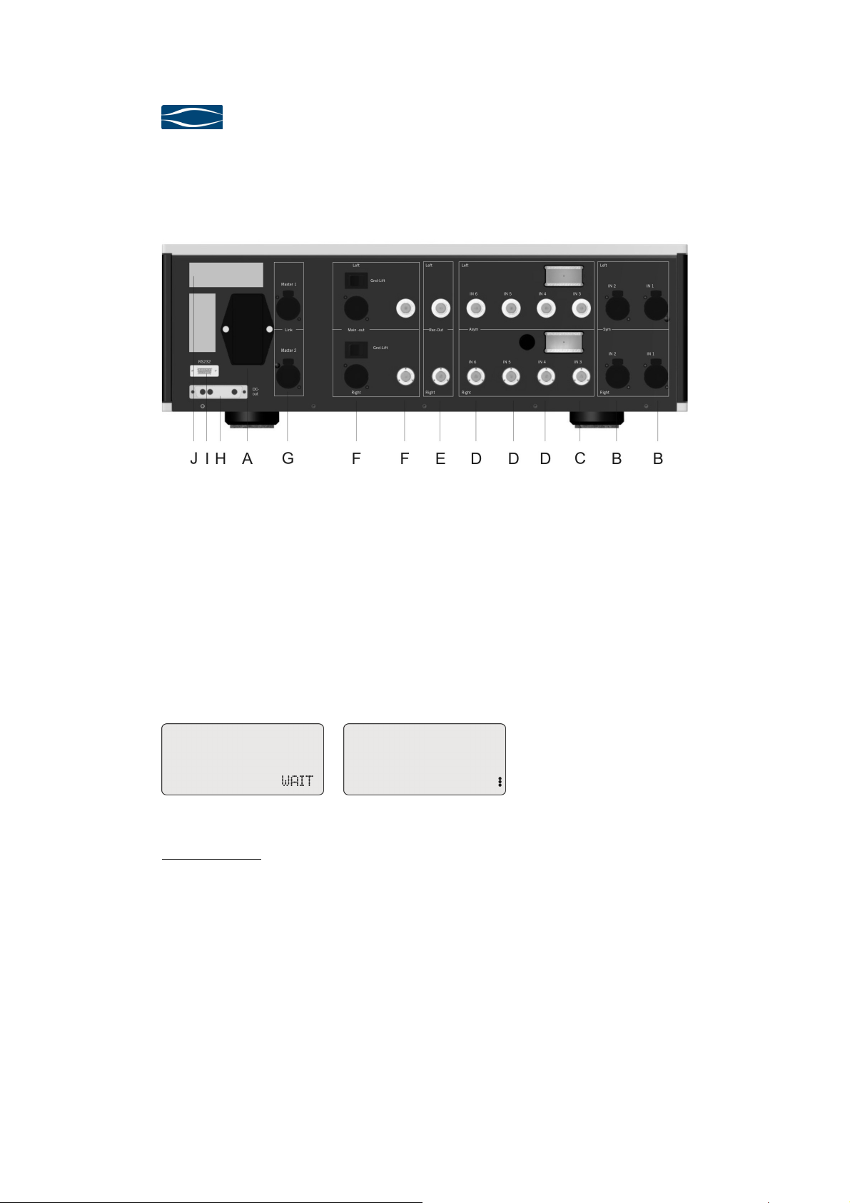
Rear panel of the preamplifier 720
4.3.1
4.3.1 Mains (A)
4.3.14.3.1
Mains (A)
Mains (A)Mains (A)
Connect the preamplifier 720 with the mains supply. The enclosed power cord is
optimised for this application.
After switch-on the power supplies of the preamplifier get started. The display
shows "WAIT". As soon as constant conditions for the power supplies are reached
the preamplifier 720 changes to operating condition OFF (red LEDs in display).
Display after switch in of the mains Display in operating condition OFF
Security advice: Only switch-off the mains connection if your preamplifier is in operating condition OFF.
Seite 12
Page 15

Preamplifier
Preamplifier 720
PreamplifierPreamplifier
User Manual
4.3.2
4.3.2 Symmetrical inputs
4.3.24.3.2
Symmetrical inputs IN 1/IN 2 (B)
Symmetrical inputsSymmetrical inputs
IN 1/IN 2 (B)
IN 1/IN 2 (B) IN 1/IN 2 (B)
Your preamplifier 720 has two symmetrical inputs IN 1/IN 2. Connect your high
quality source equipment with symmetrical cables to the preamplifier 720.
720
720720
Security advice:
4.3.3
4.3.3 Phono
4.3.34.3.3
Phono----stage
PhonoPhono
The asymmetrical input IN 3 is reserved exclusively for phono (MC). Connect your
analogue turntable with asymmetrical connectors to the preamplifier 720. Please
connect only moving coil (MC) systems.
External phono modules ensure optimal impedance matching of your cartridge and
the phono amplifier. The enclosed modules adjust the impedance to 1kΩ and
100Ω. Modules with other impedances are available through your soulution dealer.
The phono stage has a basic amplification of +54 dB or +60 dB (at 1 kHz). This
can be defined with the Program-Function Phono-Gain (chapter 5.2.11, page 29).
The phono amplifier works with an internal bandwidth of 1 MHz (-3 dB). This guarantees the most accurate reproduction of the RIAA - equalisation curve.
If required the subsonic filter RIAA-IEC can be activated.
stage IN
IN 3 (C)
stagestage
IN IN
please follow the security advices on page 6 !
3 (C)
3 (C) 3 (C)
In case you do not use your phono stage we recommend to terminate the input IN 3
with enclosed phono-termination plugs. This prevents from accidentally connecting
a line source apparatus.
Security advice: Please follow the security advices on page 6 !
Never connect a line source to the input IN 3. The phono stage is not protected
against over voltages (for sonic reasons) and would be destroyed.
Page 13
Page 16

soulution
nature of sound
4.3.4
4.3.4 Asymmetrical inputs
4.3.44.3.4
Asymmetrical inputs IN 4...IN 6 (D)
Asymmetrical inputs Asymmetrical inputs
Your preamplifier 720 has three asymmetrical inputs IN 4...IN 6. Connect your signal sources with asymmetrical cables with the preamplifier 720.
IN 4...IN 6 (D)
IN 4...IN 6 (D)IN 4...IN 6 (D)
Security advice:
4.3.5
4.3.5 Record
4.3.54.3.5
Record----Out (E)
RecordRecord
Connect the inputs of your recording device with the Record-Out terminals of the
preamplifier 720 (asymmetrical cables).
The selected Record-In signal is directed to the Record-Out terminals through a
separate signal path. Volume-, Balance- or Gain-settings do not affect the signal at
the Record-Out terminals. For level adjustments please use the respective control
functions of your recording device.
The signal present at the Record-Out terminals is buffered and has an output im-
pedance of 100Ω. Therefore cable losses are minimised and top quality music signal is available for recording.
Security advice: Please follow the security advices on page 6 !
If you connect a recording device you should define the function Record-Loop. Thus
you omit eventually harmful feedback loops.
Out (E)
Out (E)Out (E)
please follow the security advices on page 6 !
4.3.6
4.3.6 Main
4.3.64.3.6
Main----Out (F)
MainMain
The preamplifier 720 provides symmetrical as well as asymmetrical output terminals (Main-Out). Connect your amplifier to the preamplifier 720 with your preferred
cables. Due to the exceptional load stability there are no restrictions regarding the
selection of your connecting cables.
We recommend using symmetrical cables. For short cable lengths also asymmetrical
cables represent a high quality connection, top quality cable and optimal layout prerequisite. The level difference between the symmetrical and asymmetrical output
accounts for 6 dB.
Seite 14
Out (F)
Out (F)Out (F)
Page 17

Preamplifier
Preamplifier 720
PreamplifierPreamplifier
User Manual
The symmetrical output (Main-Out) additionally offers the ground lift function. The
ground-lift switch cuts off the ground connection between the audio circuit and the
symmetrical output terminal. This offers the possibility to suppress a potential
humm-loop between your preamplifier 720 and power amplifier. (Ground-Lift 1 =
ground connected, Ground-Lift 0 = ground disconnected). The housing remains
grounded independent of the ground-lift switch.
720
720720
Security advice:
4.3.7
4.3.7 LINK
4.3.74.3.7
LINK (G)
LINKLINK
The preamplifier 720 controls the start-up sequence of connected soulution components through the LINK connection (Master-Slave-principle; the preamplifier 720
is always the Master). Connect the Master Out 1 or Master Out 2 terminal of your
preamplifier 720 with the other soulution components. Each soulution component
has Next-Slave output to connect further soulution appliances.
4.3.8
4.3.8 DC
4.3.84.3.8
DC----Out (H)
DCDC
The ultra stable power supply of the preamplifier 720 is available for external soulution components (e.g. external phono preamplifier, external DAC, etc.) through the
DC-OUT connector.
(G)
(G) (G)
Out (H)
Out (H)Out (H)
Please follow the security advices on page 6!
Security advice: Never remove the security cover while your preamplifier is in operation. Always switch off your preamplifier 720 before you connect an
external device.
4.3.9
4.3.9 RS232
4.3.94.3.9
RS232 –––– Interface
RS232 RS232
The preamplifier 720 can be remote controlled through the RS232 interface. All
functions can be controlled and relevant information is provided to the controll unit.
Interface (I)
Interface Interface
(I)
(I) (I)
Page 15
Page 18
soulution
nature of sound
4.3.10
4.3.10 Type label (
4.3.104.3.10
4.4
4.4 Front panel of the preamplifier
4.44.4
Type label ( JJJJ))))
Type label (Type label (
Please note the serial number of your preamplifier 720 on page 7 of this user manual. This allows you to have the product specific data at hand without removing your
preamplifier 720 from the HiFi rack.
Front panel of the preamplifier 720
Front panel of the preamplifier Front panel of the preamplifier
720
720720
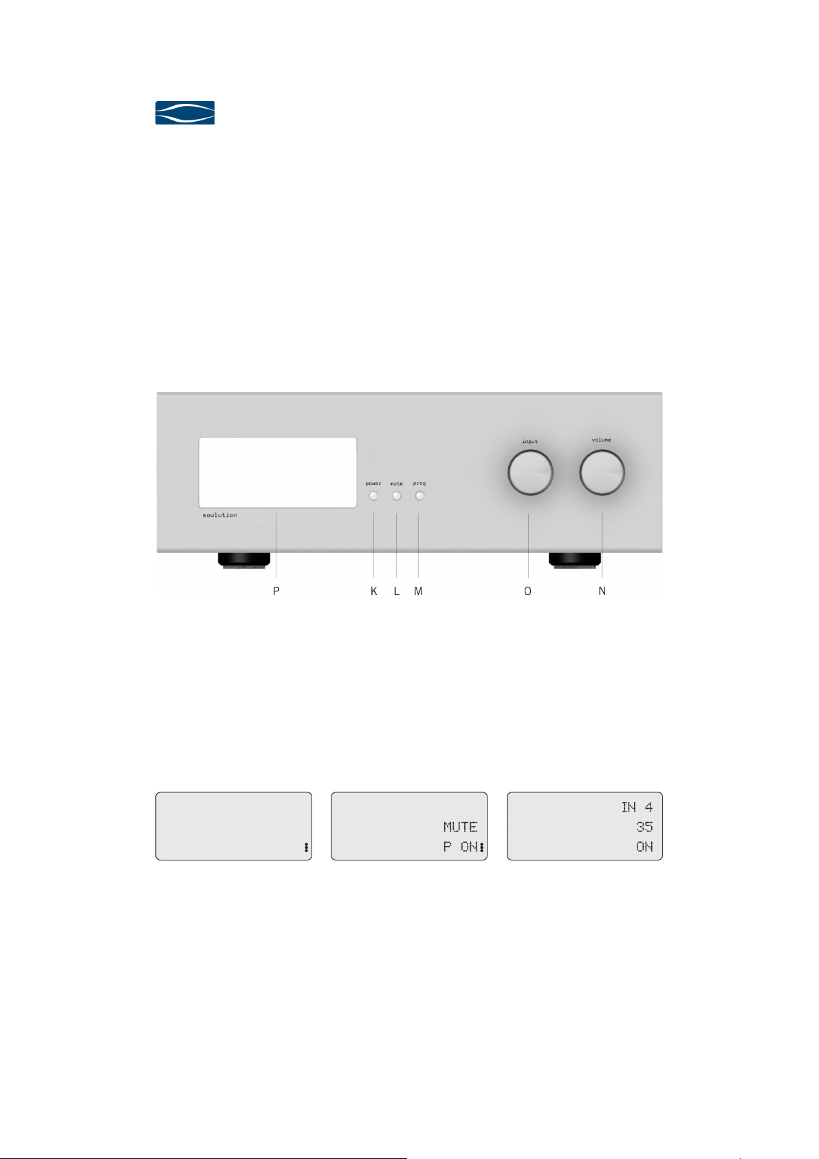
Front panel of the preamplifier 720
4.4.1
4.4.1 Power (K)
4.4.14.4.1
Power (K)
Power (K)Power (K)
With the Power-button you define the operating condition ON or OFF (red LEDs). In
operating condition OFF the audio circuits are completely disconnected from the
output terminal (Main-Out). The Main-Out terminals are only activated if the preamplifier 720 is ready for operation and if no errors are present.
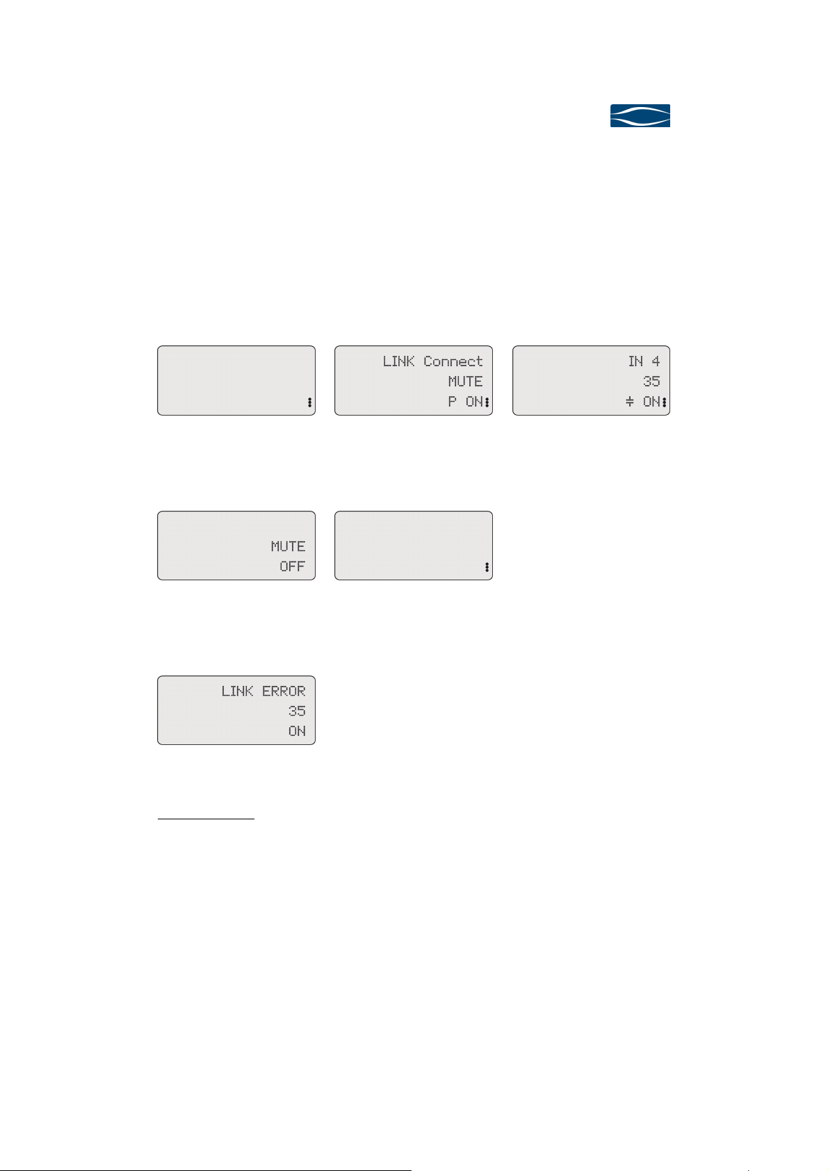
Display in operating condition OFF Display in operating condition
We suggest bringing your preamplifier 720 in operating condition OFF while you are
not listening to music. Your preamplifier 720 may be switched on with the IRremote control (Power consumption in operating condition OFF <0.5 W).
PROTECT ON
Display in operating condition ON
Seite 16
Page 19
Preamplifier
Preamplifier 720
PreamplifierPreamplifier
User Manual
LINK-System:
In case you have connected other soulution components to the preamplifier 720
with the LINK-System it remains in operating condition PROTECT ON until all connected components are switched on (Display LINK Connect).
If no errors have occurred while switching-on the other components the preamplifier
720 changes into operating condition ON.
720
720720
Display in operating condition OFF Display after switch on of LINK
components
Display in operating condition ON,
DC-protection active
When the preamplifier 720 is switched off all connected LINK components are
switched off simultaneously (operating condition OFF).
Display after switch off of LINKcomponents
Display in operating condition OFF
If an error occurs within a LINK-component while operating the display shows LINK
ERROR.
Display for an error within a LINKcomponent
Security advice: Please follow the security advices on page 6!
Unplug your preamplifier 720 from the mains before you manipulate with cables,
before cleaning, during thunder storms or before you leave for longer periods. Before
you switch off the mains bring your preamplifier 720 in operating condition OFF.
Page 17
Page 20
soulution
nature of sound
4.4.2
4.4.2 Mute (L)
4.4.24.4.2
Mute (L)
Mute (L)Mute (L)
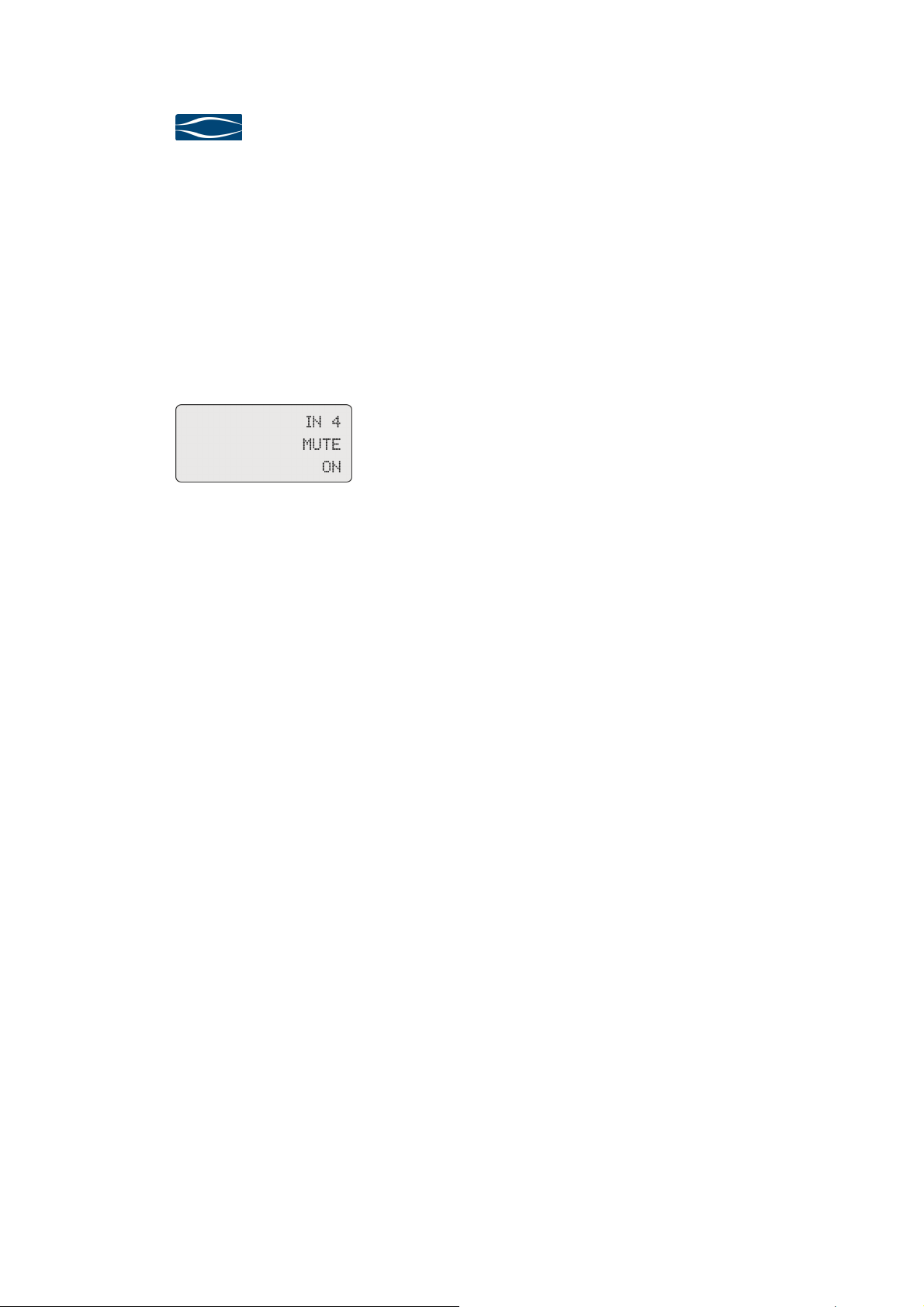
Mute is a security function which allows you disconnecting all inputs from the outputs in case of an urgency (wrong cabling, feedback loops, etc.). Mute cuts off the
symmetrical as well as the asymmetrical outputs and the record out (Display
MUTE).
For reducing the volume to a predefined level please use the function Volume-Dim.
Display in operating condition MUTE
4.4.3
4.4.3 Prog (M)
4.4.34.4.3
Prog (M)
Prog (M)Prog (M)
The Prog-button switches the preamplifier 720 between Operating-Mode and Programming-Mode. In the Programming-Mode you may adjust the preamplifier 720 to
your individual requirements.
4.4.4
4.4.4 Volume (N)
4.4.44.4.4
Volume (N)
Volume (N)Volume (N)
The Volume-knob controls the functions Volume +/- and Volume-Dim.
4.4.4.1
4.4.4.1 Volume +/
4.4.4.14.4.4.1
Volume +/----
Volume +/Volume +/
Seite 18
The preamplifier 720 disposes over a volume control range of 80 dB. The volume is
adjustable in 1 dB steps.
Display: 0 = no signal (mute)
1 = lowest level (attenuation by –79dB)
80 = maximal level (no attenuation)
Turning the Volume-knob clock wise increases the volume turning counter clock
wise decreases the volume. In order to omit too high volumes we suggest limiting
the volume individually with the function Volume-Max. When you reach the maximal
Page 21
Preamplifier
Preamplifier 720
PreamplifierPreamplifier
User Manual
level the display shows for example M 60. The volume can not be further increased
by turning the volume knob.
4.4.4.2
4.4.4.2 Volume
4.4.4.24.4.4.2
Volume----Dim
VolumeVolume
Dim
DimDim
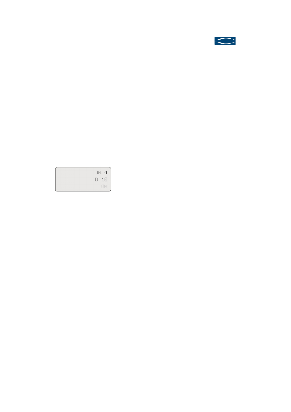
By pushing the Volume-knob the volume is reduced to the predefined level VolumeDim (Display for example „D 10“). By pushing the Volume-knob again the volume is
increased to the original level.
As long as the Volume-Dim function is active the volume can not be altered by the
Volume-knob. The volume can only be changed after the Volume-Dim function has
been deactivated.
720
720720
Display with active Volume-Dim
function
4.4.5
4.4.5 Input (O)
4.4.54.4.5
Input (O)
Input (O)Input (O)
The Input-knob controls the functions Input-Select, Record-Select and is used for
the Programming.
4.4.5.1
4.4.5.1 Input
4.4.5.14.4.5.1
Input ----Select
Select
InputInput
SelectSelect
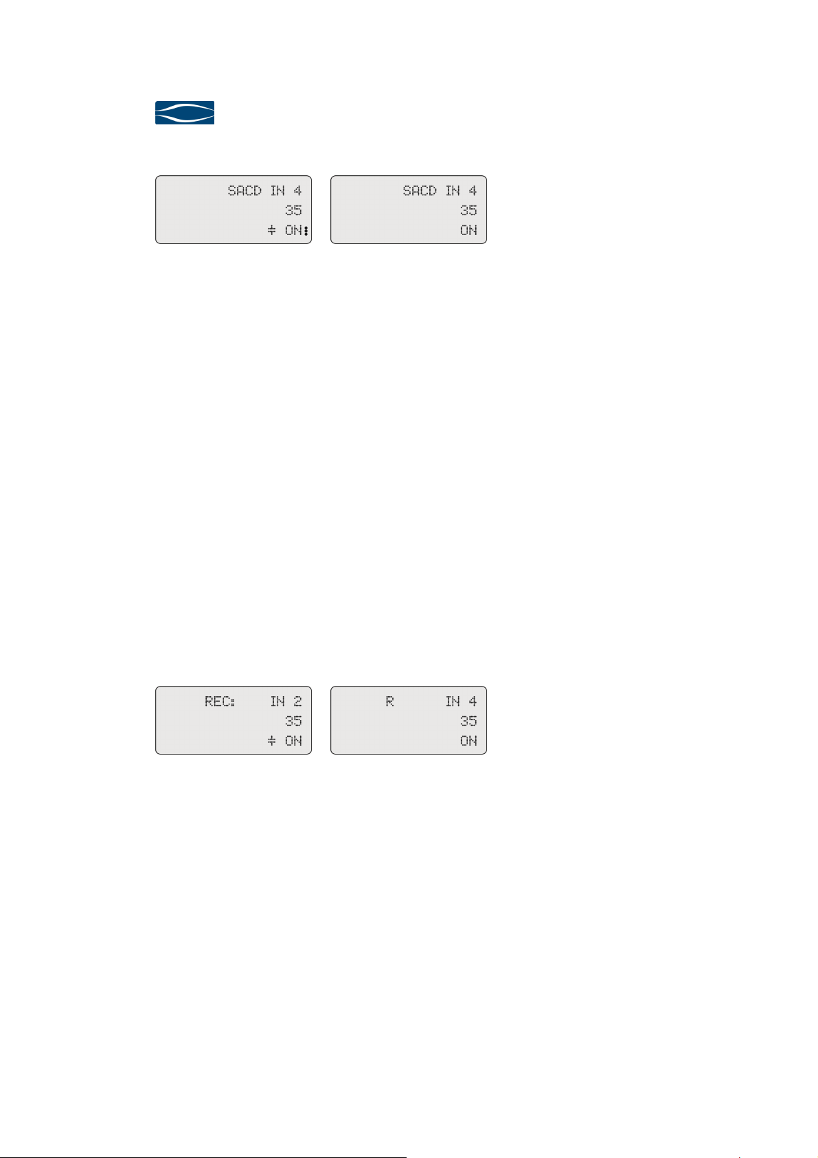
By turning the Input-knob you define which input of the preamplifier shall be connected. The display shows the input you want to select (for example SACD IN 4).
The current input remains active until the new input has been selected and the Input-knob was not turned for ca. 3 sec.
All other inputs remain completely disconnected from the preamplifier 720. Signal
and ground are (dis)connected by top class relays. Hum noise originating from eventual equalising currents between connected audio components is thus effectively
eliminated. Additionally cross-talk from inactive inputs to the active input is suppressed!
Page 19
Page 22
soulution
nature of sound
Display while selecting a new input Display after the new input is
For security reasons the DC-protection function is activated during the switch over
to the new input. If there is no DC-offset the coupling capacitor is bypassed after
ca. 15 seconds.
4.4.5.2
4.4.5.2 Record
4.4.5.24.4.5.2
Record----Select
RecordRecord
By pushing the Input-knob the preamplifier 720 changes into Record-Select-Mode.
Now you may select the input to be looped through to the Record-Out connectors.
The display shows the current Record-In for example REC IN 2. Spin the Input-knob
until the desired Record-In appears in the display. The new Record-IN is only activated when you push again the Input-knob. Thus you confirm the new selection and
the Record-Select-Mode is left. In the case you do not want to loop through any signal to the Record-Out connectors please choose REC-OFF.
The activated Record-Out disappears from the display after the Record-Select-Mode
is left. The display shows the current input connected to the Main-Out connectors.
If a Record out is activated the display shows sign “R”
Select
SelectSelect
switched on, DC-protection deactivated
Display for operating condition Record-Select-Mode
The settings of the Record-Select do not affect the signal present at the Main-Out
connectors.
4.4.5.3
4.4.5.3 Programming
4.4.5.34.4.5.3
Programming::::
ProgrammingProgramming
The Input-knob is used in the Programming-Mode for selecting Program Functions
and setting of values for the respective Program-Functions.
Seite 20
Display after exiting the RecordSelect Mode with active Record-In
Page 23

Preamplifier
Preamplifier 720
PreamplifierPreamplifier
User Manual
4.4.6
4.4.6 Display / IR
4.4.64.4.6
Display / IR----receiver
Display / IRDisplay / IR
receiver (P)
receiverreceiver
(P)
(P) (P)
The display shows all relevant information for operating your preamplifier 720 . In
operating mode the volume, the operating condition and the activated input is
shown.
Except for the Programming-Mode the display shows always the current volume
level.
720
720720
Security advice:
The IR-receiver for the remote control is located in the
lower left corner behind the display glass. For best reception do not place any objects in front of the display.
Never place your preamplifier 720 on the front panel. The display glass could get
scratched or even burst.
Page 21
Page 24

soulution
button is
the selected
of the
nature of sound
5555 Programmi
5.1
5.1 Overview
5.15.1
Programming
ProgrammiProgrammi
Overview
OverviewOverview
The available Program-Functions allow adjusting the preamplifier 720 to your individual High-Fidelity setup.
The preamplifier 720 is already programmed with default settings. Further programming is not mandatory.
We recommend to adjust the Program-Functions Start-Volume to your setup and to
limit the volume with the Program-Function Max-Volume. If you connect a recording
device we recommend implicitly activating the Program-Function Record-Loop.
Element
Element Func
ElementElement
Prog-button The Prog-button changes the preamplifier 720 from operating-
Input-knob Spinning
ng of the
of the preamplifier
ngng
of the of the
preamplifier 720
preamplifierpreamplifier
Function
FuncFunc
mode to Programming-Mode and vice versa. The preamplifier
720 remains in the respective mode until the Progpressed again.
Spinning of the Input-knob allows selecting the desired Pro-
SpinningSpinning
gram-Function. Pressing
Program-Function. Now the value domain of the selected Program-Function is active. (red LEDs in display). Spinning
Input-knob allows adjusting the desired value. Pressing
put-knob approves the respective value.
tion
tiontion
720
720720
Pressing the Input-knob approves
PressingPressing
Spinning
SpinningSpinning
Pressing the In-
PressingPressing
Seite 22
Page 25
Preamplifier
Preamplifier 720
PreamplifierPreamplifier
User Manual
5.2
5.2 Program
5.25.2
5.2.1
5.2.1 Start
5.2.15.2.1
Program----FFFFunctions
ProgramProgram
Start----In
StartStart
In
InIn
unctions
unctionsunctions
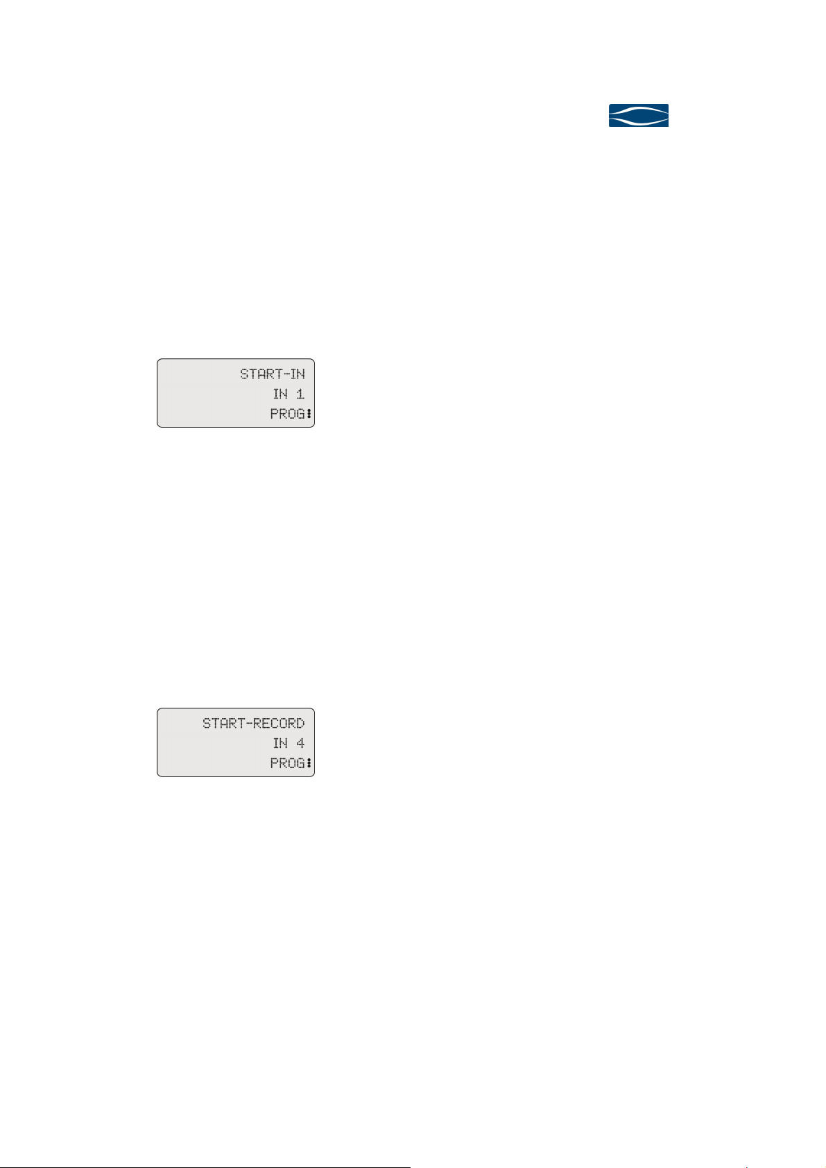
This Program-Function defines which input shall be active after start-up if your preamplifier 720. After selecting the function Start-In the display shows the value domain (red LEDs active) and you may define the desired input.
Values: IN 1, IN 2, IN 3, IN 4, IN 5, IN 6
Default: IN 1
Display for function Start-In,
value domain activated
720
720720
The selected input (IN 1...IN 6) will be activated when starting up (OFF -> ON) the
preamplifier 720 the next time.
5.2.2
5.2.2 Start
5.2.25.2.2
Start----Record
StartStart
This Program-Function defines which input shall be looped through to the recordout connectors when starting up the preamplifier 720. After selecting the function
Start-Record the display shows the value domain (red LEDs active) and you may define the desired input.
Display for function Start-Record,
value domain activated
The selected input (IN 1...IN 6) will be looped through when starting up (OFF ->
ON) the preamplifier 720 the next time. Select OFF if no signal shall be presented
at the record-out connectors.
Record
RecordRecord
Values: IN 1, IN 2, IN 3, IN 4, IN 5, IN 6, OFF
Default: OFF
Page 23
Page 26
soulution
nature of sound
5.2.3
5.2.3 Record
5.2.35.2.3
Record----Loop
RecordRecord
Loop
LoopLoop
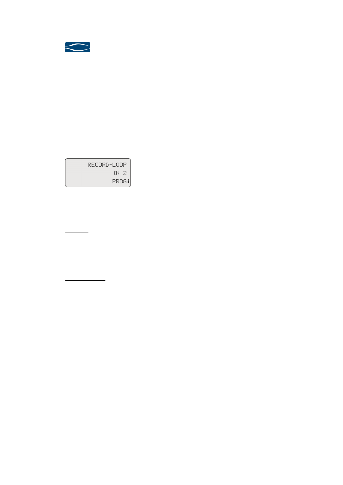
In order to avoid a feedback loop with a connected recording device you have to instruct the preamplifier 720 with which input IN 1...IN 6 a feedback loop shall be
impeded. The preamplifier 720 will now omit a feedback loop with this input.
After selecting the Program-Function Record-Loop the display shows the value domain (red LEDs active) and you may define to which input you have connected your
recording device.
Display for function Record-Loop,
Value domain activated
Values: IN 1, IN 2, IN 4, IN 5, IN 6, OFF
Default: OFF
The new setting is active as soon as you approve the value by pressing the Inputknob.
Example: You have connected the output of your recording device with the input IN 2 of the preamplifier 720. You have defined IN 2 for the program function Record-Loop. Now it is impossible to choose the input IN 2 as Record-In. The function Record-Select is not affected by the settings of the ProgramFunction Record-Loop.
Security advice: If later on you connect your recording device to another input of your preamplifier 720 you have to adjust the setting of the ProgramFunction Record-Loop.
Never connect the output of your recording device to the phono-input IN 3. The
phono stage would be destroyed immediately. Therefore the value IN 3 is not available for the Program-Function Record-Loop.
Seite 24
Page 27
Preamplifier
Preamplifier 720
PreamplifierPreamplifier
User Manual
5.2.4
5.2.4 SSSStart
5.2.45.2.4
tart----Volume
Volume
tarttart
VolumeVolume
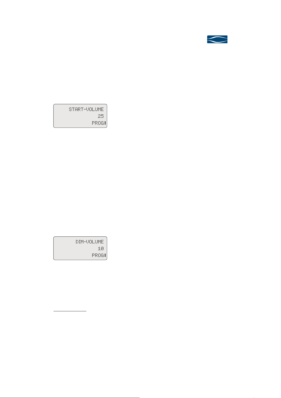
This Program-Function defines the volume when starting up the preamplifier 720.
After selecting the function Start-Volume the display shows the value domain (red
LEDs active) and you may define the desired volume level.
Value: 1...40
Default: 30
Display for function Start-Volume,
Value domain activated
While switching to the value domain of the Program-Function Start-Volume the preamplifier 720 changes the current volume to the value defined in Start-Volume.
Now you are able to judge whether the Start-Volume level is appropriate. As soon as
the value domain is left the preamplifier 720 switches back to the former volume
level.
720
720720
5.2.5
5.2.5 Dim
5.2.55.2.5
Dim----Volume
DimDim
This Program-Function defines the Dim-Volume. After selecting the ProgramFunction Dim-Volume the display shows the value domain (red LEDs active) and you
may define the desired volume level.
Display for function Dim-Volume,
Value domain activated
While switching to the value domain of the Program-Function Dim-Volume the preamplifier 720 changes the current volume to the value defined in Dim-Volume. Now
you are able to judge whether the Dim-Volume level is appropriate. As soon as the
value domain is left the preamplifier 720 switches back to the former volume level.
Security advice: Set the Dim-Volume to a moderate level. If you exchange a component of your system please check whether the setting still is appropriate.
Volume
VolumeVolume
Values: 0...40
Default: 20
Page 25
Page 28
soulution
nature of sound
5.2.6
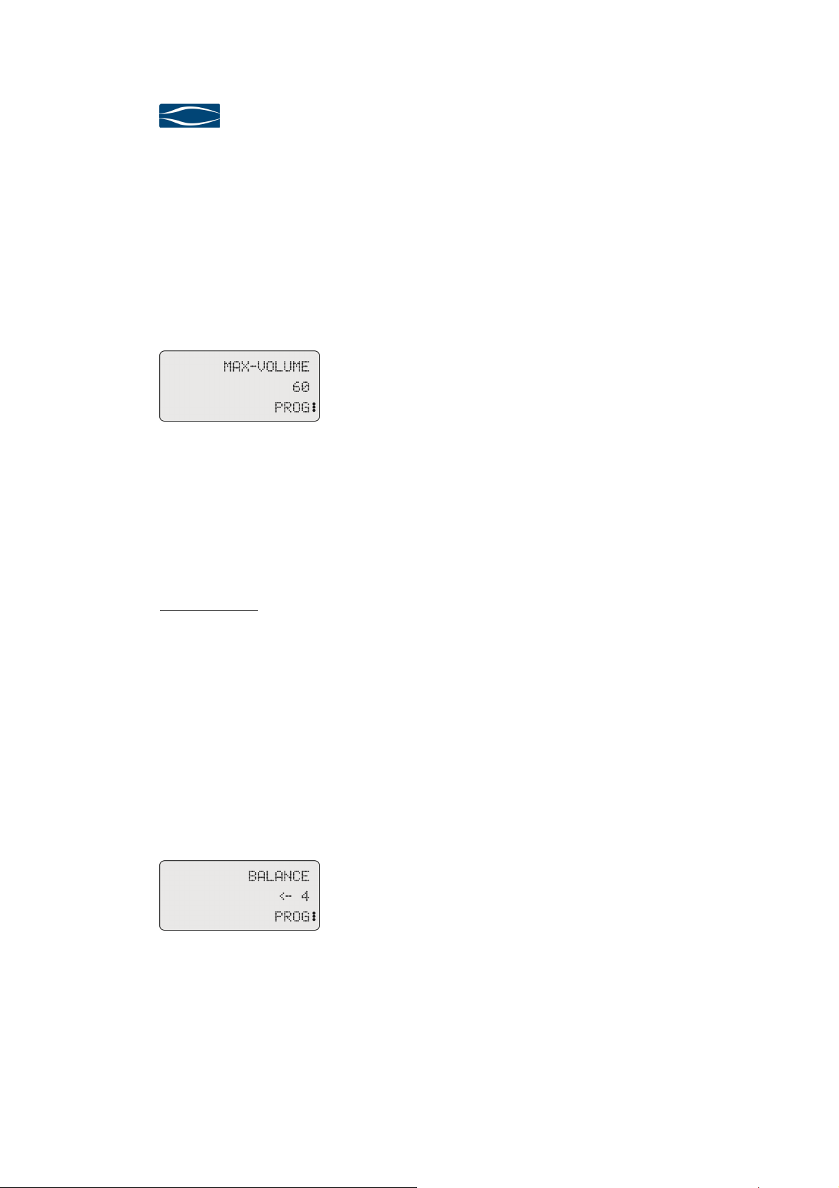
5.2.6 Max
5.2.65.2.6
Max ----Volume
Volume
MaxMax
VolumeVolume
You may limit the maximal volume level in order to avoid dangerous volume levels
through malicious handling. Especially for high efficiency loudspeakers this security
function should be used. After selecting the Program-Function Max-Volume the display shows the value domain (red LEDs active) and you may define the desired volume level.
Display for function Max-Volume,
Value domain activated
While switching to the value domain of the Program-Function Max-Volume the preamplifier 720 will not adjust the volume level for security reasons!
Values: 40...80
Default: 80
In the case you limit the volume the control range is reduced accordingly (MaxVolume = 60, the volume control range is limited to 60 dB). When you reach the
maximal volume level the display shows “M” (for example M 60)
Security advice: The settings of the Program-Functions Gain IN 1…IN
6 and Phono-Gain may provoke an additional +9 dB level difference between the
different inputs. Define the Max-Volume for the input with the highest level.
5.2.7
5.2.7 Balance
5.2.75.2.7
Balance
Balance Balance
The Program-Function Balance defines the level difference between left and right
channel. You can adjust the Balance in 1 dB steps. After selecting the ProgramFunction Balance the display shows the value domain (red LEDs active) and you
may define the desired volume level.
Display for function Balance,
Value domain activated
Values: <- 9...0...9 ->
Default: 0
Seite 26
While switching to the value domain of the Program-Function Balance the preamplifier 720 changes the current volume of left or right channel according to the setting
Page 29
Preamplifier
Preamplifier 720
PreamplifierPreamplifier
User Manual
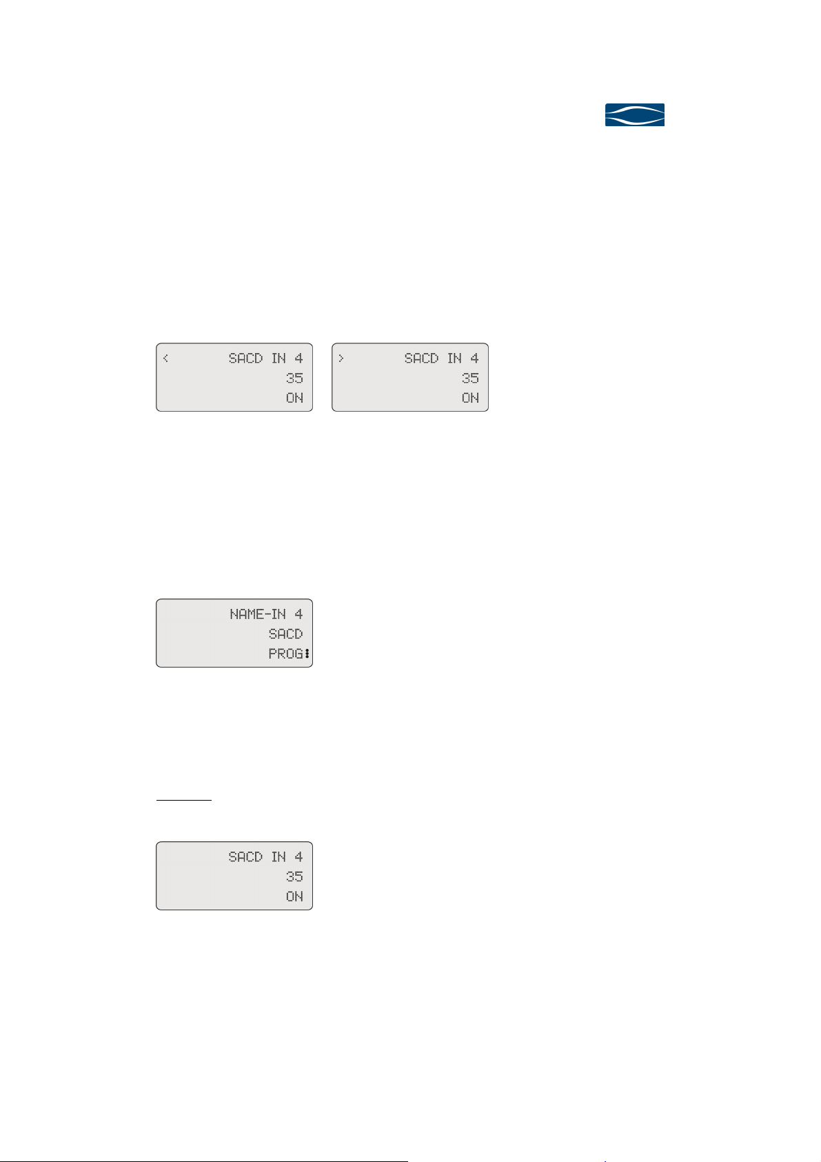
of the Balance setting. Now you are able to judge whether the Balance is appropriate.
The Balance setting reduces the maximal possible volume control range of -80dB by
the Balance setting (Balance <- 7 dB volume control range –73 dB).
After switching back to the Operating-Mode the display shows balance settings as
follows:
720
720720
Display for Balance-setting to the
left
5.2.8
5.2.8 Name IN 1...IN 6
5.2.85.2.8
Name IN 1...IN 6
Name IN 1...IN 6Name IN 1...IN 6
You may rename the inputs IN 1…IN 6 by selecting on out of the predefined source
name list. After selecting the Program-Function Name-IN 2 the display shows the
value domain (red LEDs active) and you can define the desired name for input In 2.
Display for function Name-IN 4,
Value domain activated
If you want to switch off the name please select OFF. The respective input will then
be shown as IN 1...IN 6.
Example: After you selected SACD for the input IN 4 the display
shows the input as follows.
Display for Balance-setting tot the
right
Values: AUX, AUX1, AUX2, CD, CD1, CD2,
DAC, DAT, DCC, DVD, DVD1, DVD2,
DVDA, HD, HiMD, LD, MD, MP3, PC,
PHON, SACD, TAPE, TUNE, TV, DVB,
DAB, OFF
Default: OFF
Display for Name-IN 4 = SACD
The new input names IN 1…IN 6 will be activated after you have left the Programming-Mode.
Page 27
Page 30
soulution
nature of sound
5.2.9
5.2.9 Bandw
5.2.95.2.9
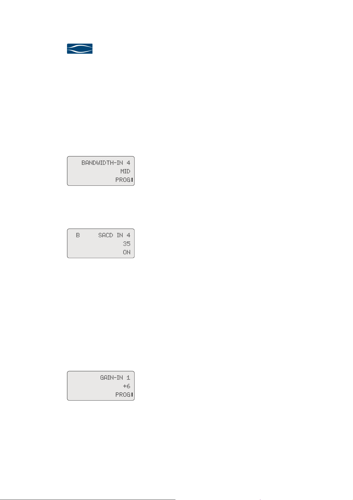
Bandwidth IN 1…IN 6
BandwBandw
idth IN 1…IN 6
idth IN 1…IN 6idth IN 1…IN 6
Digital signal sources can emit remarkable levels of high frequency noise through
the connecting cables. This will lower the sonic performance of your overall system.
You may limit the bandwidth of each input IN 1…IN 6 individually depending on
the quality of the source signal. After selecting the Program-Function Bandwidth-IN
1 the display shows the value domain (red LEDs active) and you can limit the
bandwidth for input In 1.
Display for function Bandwidth-IN 4
Value domain activated
Values: high: no limitation
mid: 200 kHz, -3dB
low: 20 kHz, -3dB
Default: high
After you have left the Programming-Mode the display shows the bandwidth limitation as follows.
Display for Bandwidth limitation of
input IN 4
5.2.10
5.2.10 Gain IN 1...IN 6
5.2.105.2.10
Gain IN 1...IN 6
Gain IN 1...IN 6Gain IN 1...IN 6
Different signal sources have different output levels. You can adjust the level for
each input by 0/+3/+6/+9 dB individually. After selecting the Program-Function
Gain-IN 1 the display shows the value domain (red LEDs active) and you can adjust
the level for input In 1.
For the input IN 3 (phono) exists additionally the Program-Function Phono Gain
which defines the basic amplification in to levels (+54 dB, +60 dB)
Values: 0/+3/+6/+9
Seite 28
Default: 0
Display for function Gain-IN 1,
Value domain activated
Gain adjustments are immediately performed so you can check whether the Gainsetting is appropriate.
Page 31
Preamplifier
Preamplifier 720
PreamplifierPreamplifier
User Manual
720
720720
Security advice:
level. Set the gain for this input to +0 dB. Now adjust the other inputs accordingly.
Please use a moderate volume level to do so.
If you exchange signal sources you should check whether the gain setting are still
appropriate. If you run a high level signal source with a high gain the output signal
could get distorted.
5.2.11
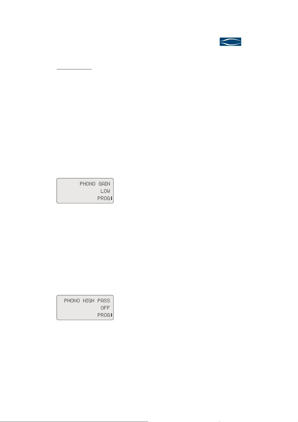
5.2.11 Phono Gain
5.2.115.2.11
Phono Gain
Phono GainPhono Gain
This Program-Function allows you to adjust the basic amplification of Phonoamplifier to the requirements of your cartridge. Additionally you have the possibility
to use the function Gain-In 3 to further adjust the level of the phono amplifier.
Display for function Phono Gain,
Value domain activated
Define which signal source has the highest output
Values: high +54 dB @ 1 kHz
low +60 dB @ 1 kHz
Default: low
Phono Gain settings are immediately performed so you can check whether the setting is appropriate.
5.2.12
5.2.12 Phono High Pass
5.2.125.2.12
Phono High Pass
Phono High PassPhono High Pass
This Program-Function (de)activates the subsonic filter (RIAA-IEC; -3 dB @ 20 Hz)
of the phono amplifier.
Display for function Phono High
Pass, Value domain activated
The settings of the Program-Function Phono High Pass are immediately executed
for a direct feedback.
Phono High Pass = OFF should be used only for top quality LP’s and decoupled
turntables. For security reasons we recommend to activate the subsonic filter.
Values: ON, OFF
Default: ON
Page 29
Page 32
soulution
nature of sound
5.2.13
5.2.13 Surround
5.2.135.2.13
Surround----IN
SurroundSurround
IN
ININ
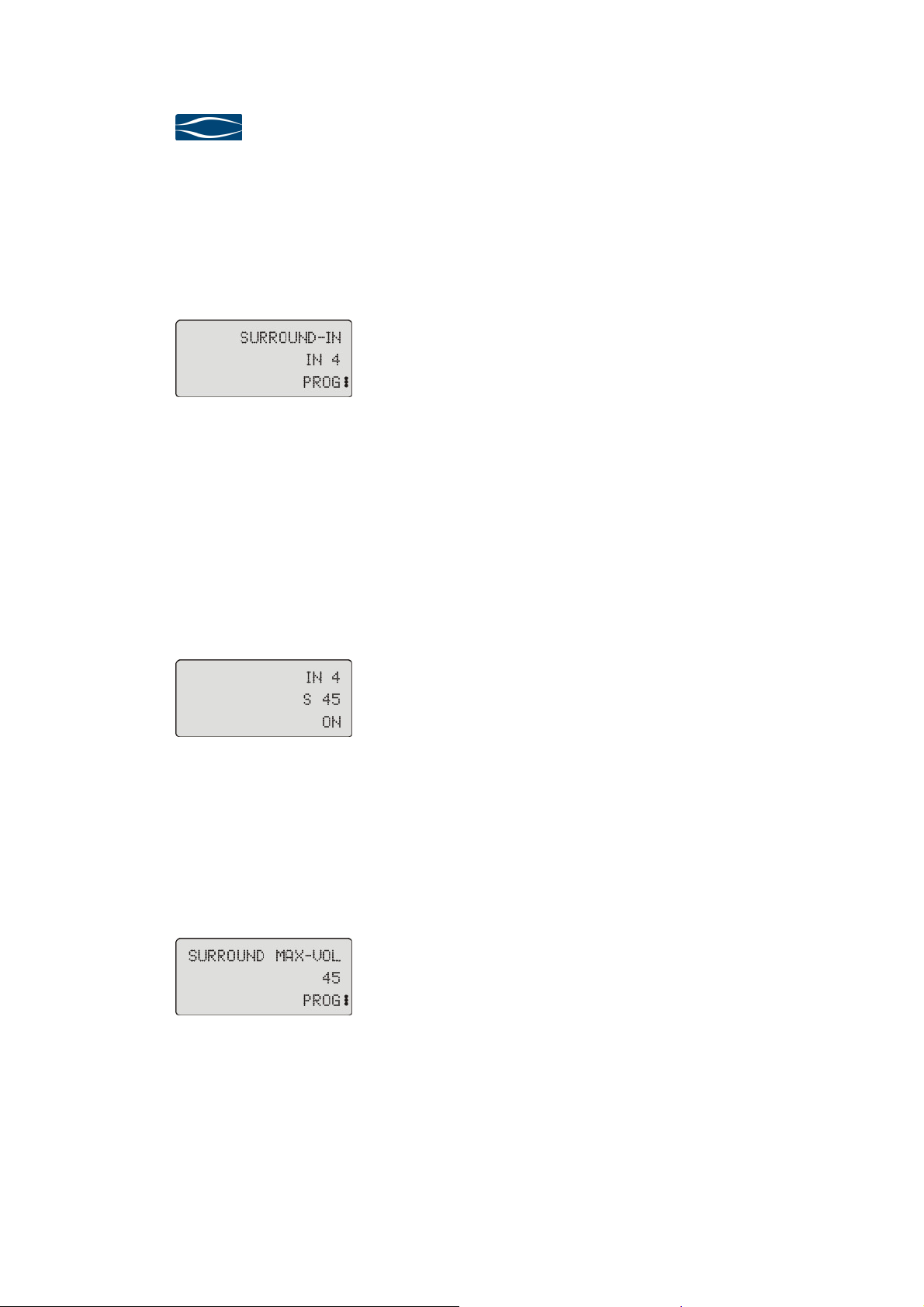
The Program-Function Surround-IN activates the Surround-Mode for the selected
input.
Display for function Surround-IN,
Value domain activated
In Surround-Mode the settings for Volume and Balance do not have any influence.
The input-signal present at the Surround-IN is transferred to the outputs with the
level defined in Program-Function Surround Max-Vol.
Values: IN 1, IN 2, IN 4, IN 5, IN 6, OFF
Default: OFF
The Program-Function Surround-IN is not available for the input IN 3 (phono).
If you have activated the Surround-IN for input IN 4 the display will show as follows.
Display for activated Surround-IN,
input IN 4
and Surround Max-Vol = 45.
5.2.14
5.2.14 Surround Max
5.2.145.2.14
Surround Max----Vol
Surround MaxSurround Max
The Program-Function Surround Max-Vol defines the output level for the SurroundIN. The setting of this function has no impact if the Surround-IN is OFF.
Display for function Surround Max.Vol, Value domain activated
Vol
VolVol
Values: 40…80
Default: 40
Seite 30
You can select the optimal volume level at the output of the preamplifier 720 depending on your surround system. The level can be adjusted in 1 dB steps.
Page 33
Preamplifier
Preamplifier 720
PreamplifierPreamplifier
User Manual
Level: 70 = - 0.5 dB total gain input to output (sym)
71 = + 0.5 dB total gain input to output (sym)
Please be aware that the Program-Functions Gain-IN 1…IN 6 remain active in the
Surround-Mode. If you select for instance + 3dB gain for the Surround IN the level
71 will result in a total gain input to output of 3.5 dB.
5.2.15
5.2.15 Brightness
5.2.155.2.15
Brightness
BrightnessBrightness
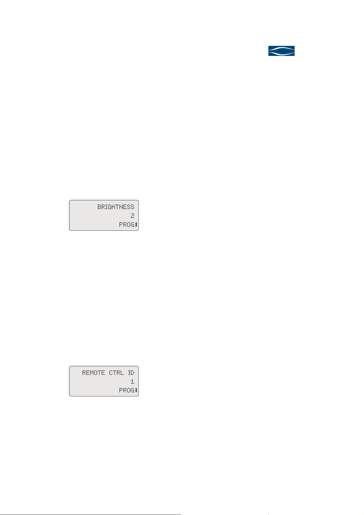
The intensity of the display can be adjusted in three steps.
Values: 1 = low
2 = medium
3 = high
Display for function Brightness,
Value domain activated
Default: 3
720
720720
The intensity is adjusted immediately.
5.2.16
5.2.16 Remote Ctrl
5.2.165.2.16
Remote Ctrl ID
Remote CtrlRemote Ctrl
If you use two different preamplifiers or the Remote Ctrl ID of the preamplifier 720
is already used by another device of your HiFi-setup you can change the identification of your preamplifier 720. Factory default is 1 (For changing the Remote ctrl ID
of the remote control 720/740 please refer to chapter 6.2.11, page 36). After selecting the Program-Function Remote Ctrl ID the display shows the value domain
(red LEDs active) and you can select the desired ID.
Display for function Remote Ctrl ID,
Value domain activated
The new Remote Control ID will be activated after the Programming-Mode is left.
ID
ID ID
Values: 1, 2
Default 1
Page 31
Page 34
soulution
nature of sound
If you change the Remote Ctrl ID the preamplifier 720 can only be controlled by the
remote control 720/740 after you have switched the Remote Ctrl ID of the remote
control 720/740 alike.
5.2.17
5.2.17 Load
5.2.175.2.17
Load----Default
Default
LoadLoad
DefaultDefault
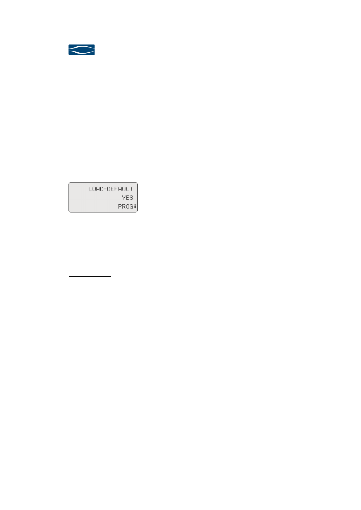
In case you want to overwrite all your individual settings by the factory default values you select the Program-Function Load-Default and you confirm with YES. The
following values will be loaded.
Display for function Load-Default,
Value domain activated
Security advice: Please note your personal settings in the table
„Individual Settings“ on page 44.
5.2.18
5.2.18 Software
5.2.185.2.18
Software----Info
SoftwareSoftware
This function shows the version of software installed on your preamplifier 720.
Info
InfoInfo
Start-In: IN 1
Start-Record: OFF
Record-Loop: OFF
Start-Volume: 30
Dim-Volume: 20
Max-Volume: 80
Balance: 0
Name IN 1..6: OFF
Bandwidth IN 1.. 6 HIGH
Gain IN 1.. 6: 0
Phono-Gain: LOW
Phono High Pass: ON
Surround-IN: OFF
Surround-Max-Vol: 40
Brightness: 3
Remote Ctrl ID 1
Seite 32
Page 35
Preamplifier
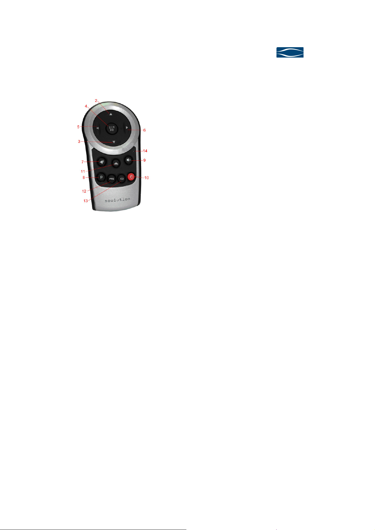
The remote control controls all functions of the
s
the
buttons of the remote control
of the soulution
. This is
Preamplifier 720
PreamplifierPreamplifier
User Manual
720
720720
6666 Remote control
Remote control
Remote controlRemote control
6.1
6.1 Start of operation and maintenance
6.16.1
Start of operation and maintenance
Start of operation and maintenanceStart of operation and maintenance
The remote control requires 2 AAA batteries (enclosed in the scope of delivery). We
recommend using only top quality products.
soulution preamplifiers, integrated amplifier
and CD/SACD-Players. You can also access
Program-Functions of these products.
The Volume +/will always control the volume
preamplifier or integrated amplifier
also the case when changing the remote control to CD-mode.
Exchange of batteries:
-
open the battery tray on the rear side.
-
insert the batteries into the tray as indicated.
Ensure correct polarity of the batteries.
-
close the tray with corresponding screw.
-
dispose the exhausted batteries
6.2
6.2 Handling
6.26.2
6.2.1
6.2.1 IR
6.2.16.2.1
Handling
HandlingHandling
IR----Transmitter (1)
Transmitter (1)
IRIR
Transmitter (1)Transmitter (1)
Ensure that the IR-Transmitter is not covered and that the IR-Receiver is not hided
by any objects. The remote control works up until a distance of 5m and a maximal
angel of incident of ±45°.
Page 33
Page 36

soulution
nature of sound
6.2.2
6.2.2 Input ±
6.2.26.2.2
Input ± / Next Track
Input ± Input ±
/ Next Track, (5/6)
/ Next Track/ Next Track
PRE-mode: The Input ± buttons switch between the different inputs. With
CD-modus: The Next Track buttons skip the tracks forward or backward.
In Programming-Mode (Prog-button) the Input ± buttons allow to select the desired
function and the Enter-button confirms the selection. If the value domain of a function is activated the Input ± buttons allow setting the new value and Enter-button
confirms the new setting.
, (5/6)
, (5/6), (5/6)
the Enter-button you change to the Record-select-mode. In this
mode the Input ± buttons allow to select the Record-IN.
6.2.3
6.2.3 Volume
6.2.36.2.3
Volume----Dim / Play
VolumeVolume
Dim / Play ----Pause
Dim / PlayDim / Play
PRE-mode: Pressing the Volume-Dim button (de)activates the Volume Dim
CD-mode: The Play-Pause button controls the Play/Pause function of the
6.2.4
6.2.4 Volume ± (2,3)
6.2.46.2.4
Volume ± (2,3)
Volume ± (2,3)Volume ± (2,3)
The Volume ± buttons control always the volume of the preamplifier, integrated amplifier irrespective of the PRE-/CD-mode of the remote control.
6.2.5
6.2.5 Mute (9)
6.2.56.2.5
Mute (9)
Mute (9)Mute (9)
PRE-mode: The Mute-button controls always the mute function of the pre-
Pause (4)
PausePause
(4)
(4)(4)
function of the preamplifier or the integrated amplifier.
CD/SACD-Players
amplifier, integrated amplifier. The mute function disconnects
the Main-Out and the Record-Out connectors.
Seite 34
CD-mode: no function
Page 37

Preamplifier
Preamplifier 720
PreamplifierPreamplifier
User Manual
6.2.6
6.2.6 Open/Close (11)
6.2.66.2.6
Open/Close (11)
Open/Close (11) Open/Close (11)
PRE-Mode: no function.
CD-mode: The Open/Close button controls the drawer of the player.
6.2.7
6.2.7 Prog
6.2.76.2.7
Prog----button
button (8)
ProgProg
buttonbutton
(8)
(8) (8)
PRE-mode: The Prog-button switches the preamplifier, integrated amplifier
between Operating-Mode and Programming-Mode.
CD-mode: The Prog-button switches the CD/SACD-Player between Operat-
ing-Mode and Programming-Mode.
720
720720
6.2.8
6.2.8 PRE
6.2.86.2.8
PRE----button
PREPRE
Pressing the PRE-button switches the remote control to PRE-mode for the control of
the preamplifiers or integrated amplifiers. While pressing the buttons of the remote
control the red LED (14) will light up.
6.2.9
6.2.9 CD
6.2.96.2.9
CD----button
CDCD
Pressing the CD-button switches the remote control to CD-mode for the control of
the CD/SACD-Players. While pressing the buttons of the remote control the blue
Leds under the Play/Pause button (4) will light up.
button (12)
(12)
buttonbutton
(12) (12)
button (13)
buttonbutton
(13)
(13) (13)
Page 35
Page 38

soulution
nature of sound
6.2.10
6.2.10 Power (10)
6.2.106.2.10
6.2.11
6.2.11 Remote Ctrl ID
6.2.116.2.11
Power (10)
Power (10)Power (10)
PRE-mode: The Power-button defines the operating condition ON or OFF of
CD-mode: The Power-button defines the operating condition ON or OFF of
Remote Ctrl ID
Remote Ctrl IDRemote Ctrl ID
PRE-mode: Change the transmitter Remote Ctrl ID of the remote control as
ID 1: Input+ button (6), Input- button (5) and Power (10)
the preamplifier, intzegrated amplifier.
the CD/SACD-Player.
follows:
ID 2: Input+ button (6), Input- button (5) and Mute (9)
Press the respective buttons for approximately 5 seconds. The
remote control confirms the new ID via red LED on its front.
The Remote Control ID of the preamplifier, integrated amplifier
has to be changed as well by selecting the Program-Function
Remote Control ID, otherwise the preamplifier, integrated amplifier will not react to the remote control no more.
CD-mode: The Remote Ctrl ID can not be changed.
Seite 36
Page 39

Preamplifier
Preamplifier 720
PreamplifierPreamplifier
User Manual
720
720720
7777 Protection functions of the preamplifier
Protection functions of the preamplifier 720
Protection functions of the preamplifierProtection functions of the preamplifier
Comprehensive protection functions ensure a secure operation and long durability.
The preamplifier 720 disposes over the following functions:
Overcurrent
Overcurrent::::
OvercurrentOvercurrent
For currents > 1 Ampere at the Main-Out the preamplifier 720 shuts down automatically.
DC
DC----PROTECT
PROTECT::::
DCDC
PROTECTPROTECT
Your preamplifier 720 is protected against DC-offset at the inputs IN 1...IN 6. The
input signal is permanently monitored for DC-components. As soon as a DC-offset is
detected a coupling capacitor is switched into the signal path. This capacitor is bypassed if the DC-offset has ceased for at least 15 seconds. The display shows the
symbol for the capacitor (╪).
720
720 720
While switching between inputs the capacitor is activated automatically for security
reasons. This is not
a malfunction of your source device.
Fuse
Fuse::::
FuseFuse
The mains connection has a fuse which protects your preamplifier 720 against too
high power consumption. The fuse is located within the mains switch on the rear
side of the preamplifier 720.
Model 220-240 V, 50-60Hz 2A/T 250V micro fuse 5x20mm
Model 100-120 V, 50-60Hz 4A/T 250V micro fuse 5x20mm
Page 37
Page 40

soulution
Check the cabling to the mains supply. Eventually replace
, signal sources
fier to your loudspeakers, whether
rce device is
or
ay shows
display shows
. This error may also
nature of sound
8888 Trouble shooting
Trouble shooting
Trouble shootingTrouble shooting
Error
Error Action
ErrorError
No
No Display
Display
No No
DisplayDisplay
No music
No music
No musicNo music
POWER FAIL
POWER FAIL
POWER FAILPOWER FAIL
OVERCURRENT
OVERCURRENT
OVERCURRENTOVERCURRENT
Action
ActionAction
the fuse of your preamplifier 720.
Check the cabling to your power amplifier
and from the power ampli
you have selected the correct input, the sou
muted and if the power amplifier is switched on.
If the power supply to the audio channels is interrupted
an error in the power supply unit has occurred the preamplifier 720 is shut down automatically. The displ
POWER FAIL.
If the current at the Main-Out exceeds 1 ampere the preamplifier 720 is shut down automatically. The
OVERCURRENT.
Check the cabling to the power amplifier
be provoked by defect or switched off power amplifier.
8.1
8.1 Actions after the appearance of an error
8.18.1
Actions after the appearance of an error
Actions after the appearance of an errorActions after the appearance of an error
If you con not identify the error please disconnect the mains supply (before you disconnect the preamplifier 720 has to be in operating condition OFF) and contact
your soulution dealer.
Seite 38
Page 41

Preamplifier
Preamplifier 720
PreamplifierPreamplifier
User Manual
720
720720
9999 CCCCare and maintenance
9.1
9.1 Burn
9.19.1
are and maintenance
are and maintenanceare and maintenance
Burn----in
in
BurnBurn
inin
The preamplifier 720 will play on top level immediately after the first placing into
operation. However during the first 20-50 hours of operation you will notice a further improvement of its sonic qualities.
9.2
9.2 Longlife
9.29.2
Longlife----precaution
LonglifeLonglife
precaution ssss
precautionprecaution
We use only highest quality components for the preamplifier 720. Components
prone to aging are kept under constant voltages in stand-by (OFF) condition in order
to further increase their lifetime. In stand-by (OFF) condition the preamplifier 720
dissipates ca. 6 Watts.
Security advice:
Unplug your preamplifier 720 if you leave for longer
periods
9.3
9.3 Cleaning
9.39.3
Cleaning
CleaningCleaning
Please use a soft towel for the cleaning of your preamplifier 720 . We recommend
the use of a nonabrasive micro fibre towel. Please do not employ any solvents.
Security advice: Liquidity is not allowed to enter the preamplifier 720.
The electronic may be damaged seriously.
.
Page 39
Page 42

soulution
nature of sound
10
10 Service
1010
11
11 Warranty
1111
Service
ServiceService
If your soulution preamplifier needs service please contact your soulution dealer.
For further information see www.soulution-audio.com
Warranty
WarrantyWarranty
All soulution products are guaranteed against defects in material and workmanship
for five years from date of purchase.
The guarantee is void if the preamplifier 720 has been subject to misuse or negligence or has been modified, repaired or opened by a non authorised person without
written authorisation of Spemot AG.
For the return transport to our premises please use exclusively the original packaging. Transport damages are not subject to this guarantee, repairs will be charged.
We recommend effecting transport insurance.
If you not posses the original packaging no more please contact your soulution
dealer.
Basic repairs may be completed by your soulution dealer. Please clarify whether he
is able to do the work before you send the preamplifier 720 back to us.
Seite 40
Page 43

Preamplifier
Preamplifier 720
PreamplifierPreamplifier
User Manual
12
12 Specific
1212
Specification
SpecificSpecific
Specific
Specification
SpecificSpecific
General
General
GeneralGeneral
ationssss
ationation
ation Data
ationation
Data
DataData
Nominal voltage Model 220-240V 220 - 240 V, 50-60 Hz
Model 100–120V 100 – 120 V, 50-60 Hz
Nominal rating 250 W
Power consumption (OFF) <0.5 W
Power consumption (ON) 60 W
Line
Line----inputs
inputs:::: IN 1/IN 2, IN 4...IN 6
LineLine
inputsinputs
IN 1/IN 2, IN 4...IN 6
IN 1/IN 2, IN 4...IN 6IN 1/IN 2, IN 4...IN 6
Amplification symmetrical (IN 1/IN 2) +9.5...+18.5 dB
asymmetrical (IN 4...IN 6) +3.5...+12.5 dB
Frequency response DC-1 MHz
Slew rate 400 ns
THD+N <0.0006 %
Signal-to-Noise ratio 140 dB
Crosstalk
Input impedance
Phono
Phono----Input
PhonoPhono
Input :::: IN 3
InputInput
symmetrical (IN 1/IN 2)
asymmetrical (IN 4...IN 6)
IN 3
IN 3IN 3
105
47
dB
2
kΩ
kΩ
Amplification +54...+60 dB
Amplifier bandwidth (internal) DC-1 MHz
Slew rate 400 ns
THD+N <0.0006 %
Input-Impedance (no adaptation) 1
Outputs
Outputs
OutputsOutputs
Voltage Main-Out symmetrical max. 16
Main-Out asymmetrical max. 8
kΩ
Vrms@100Ω
Vrms@100Ω
Current max. 1 A
Impedance Main-Out symmetrical 2
Main-Out asymmetrical 2
Record-Out 100
LINK-Out +12 V
Dimensions
Dimensions
DimensionsDimensions
Ω
Ω
Ω
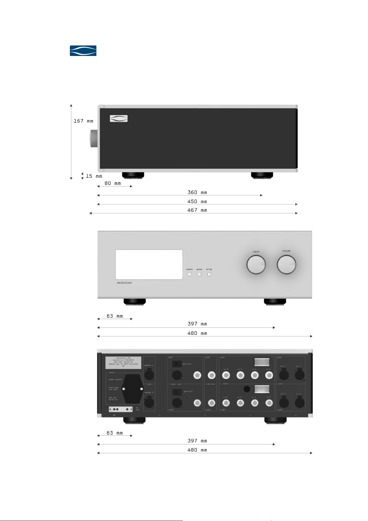
Dimensions 480x450x167 mm
Weight ca. 30 kg
720
720720
Technical specifications are subject to change without prior notification.
Page 41
Page 44
soulution
nature of sound
13
13 Dimension
1313
Dimensionssss
DimensionDimension
Seite 42
Page 45
Preamplifier
power supply is
is switched on it changes to
condition P ON. The audio power supply unit is
conditions are reached and no
is ready for
or an
is shut down automatically. The display shows POWER
m-
shows
In the case other soulution components are controlled via the
LINK connection the preamplifier shows in the display (LINK:
Preamplifier 720
PreamplifierPreamplifier
User Manual
14
14 Definition
1414
Definition ssss
DefinitionDefinition
Operating conditions
Operating conditions
Operating conditionsOperating conditions
OFF
OFF
OFFOFF
(Standby)
In operating condition OFF only the standbyactive. Power consumption of <0.5 Watts.
As soon as the preamplifier 720
the operating
P ON
P ON
P ONP ON
(PROTECT ON)
started and the audio channels are checked for potential errors. When constant operating
errors are detected the preamplifier 720 changes into operating condition ON.
ON
ON
ONON
In operating condition ON the preamplifier 720
operation.
If the power supply to the audio channels is interrupted
POWER FAIL
POWER FAIL
POWER FAILPOWER FAIL
error in the power supply unit has occurred the preamplifier
720
FAIL.
If the current at the Main-Out exceeds 1 ampere the prea
OVER
OVER----CURRENT
OVEROVER
CURRENT
CURRENTCURRENT
plifier 720 is shut down automatically. The display
OVERCURRENT.
720
720720
LINK ERROR
LINK ERROR
LINK ERRORLINK ERROR
ERROR) if an error has occurred.
Labelling
Labelling
LabellingLabelling
SYM
SYM Abbreviation for symmetrical connectors.
SYMSYM
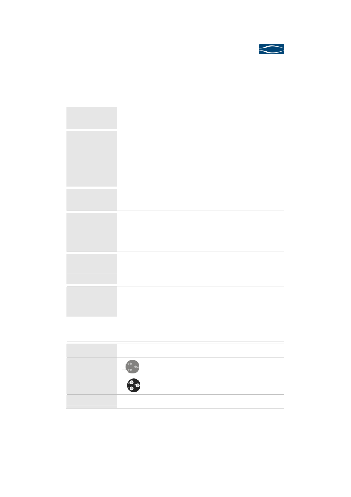
XLR Female
XLR Female
XLR FemaleXLR Female
XLR Male
XLR Male
XLR MaleXLR Male
ASYM
ASYM Abbreviation for asymmetrical connectors.
ASYMASYM
1. Ground, 2. + Phase, 3. - Phase
1. Ground, 2. + Phase, 3. - Phase
Page 43
Page 46

soulution
nature of sound
15
15 Individual Settings
1515
Individual Settings
Individual SettingsIndividual Settings
Function
Function Setting
FunctionFunction
Start-In IN 1
Start-Record OFF
Record-Loop OFF
Start-Volume 40
Dim-Volume 10
Max-Volume 80
Balance 0
Name IN 1 OFF
Name IN 2 OFF
Setting Default
SettingSetting
Default----Value
DefaultDefault
Value
ValueValue
Name IN 3 OFF
Name IN 4 OFF
Name IN 5 OFF
Name IN 6 OFF
Bandwidth-IN 1 HIGH
Bandwidth-IN 2 HIGH
Bandwidth-IN 3 HIGH
Bandwidth-IN 4 HIGH
Bandwidth-IN 5 HIGH
Bandwidth-IN 6 HIGH
Gain IN 1 0
Gain IN 2 0
Gain IN 3 0
Gain IN 4 0
Gain IN 5 0
Gain IN 6 0
Phono Gain LOW
Seite 44
Phono High Pass ON
Surround-IN OFF
Surround Max-Vol 40
Brightness 3
Remote Ctrl ID 1
Page 47

Page 48

Spemot AG
Industriestrasse 70
CH-4657 Dulliken
www.soulution-audio.com
soulution
nature of sound
part.no
part.no.... 92130
92130
part.nopart.no
9213092130
 Loading...