

Page 1

The SOTABEAMS Click2Tune for ICOM is a handy accessory
that gives you a convenient low power tune facility for your
ICOM radio. It's easy to build and you will be using it in
under an hour! Do take a few minutes to read right through
the instructions before you start.
SOTABEAMS last updated 30/08/2017 Page 1 of 12
Page 2
Revision History
9th August 2017 – First Revision
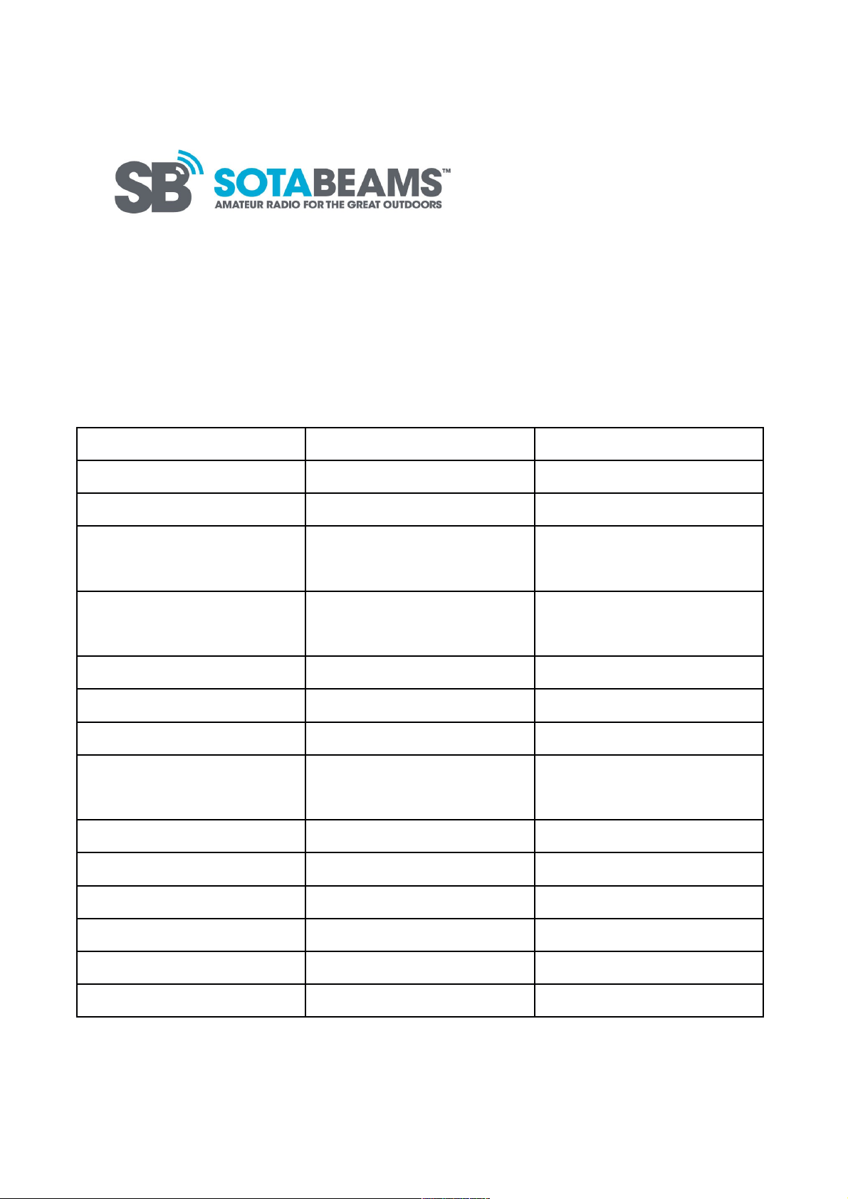
Icom Click2Tune Packing List
Item Number Comments
PCB 1
820R Resistor 1 Grey, red, brown,
gold
470R Resistor 1 Yellow, purple,
brown, Gold
Button 1
Button blue Square 1
Metal contacts 4
Plastic connector
block
1
Foam Pad 1 2cm
Red Heat shrink 3cm 3:1 - 6mm
Blue Heat shrink 6cm 2:1 - 16mm
Black wire 4cm
Black Cable 1m 4 core screened
SOTABEAMS sticker 1
SOTABEAMS last updated 30/08/2017 Page 2 of 12
Page 3
Assembling the PCB
1)
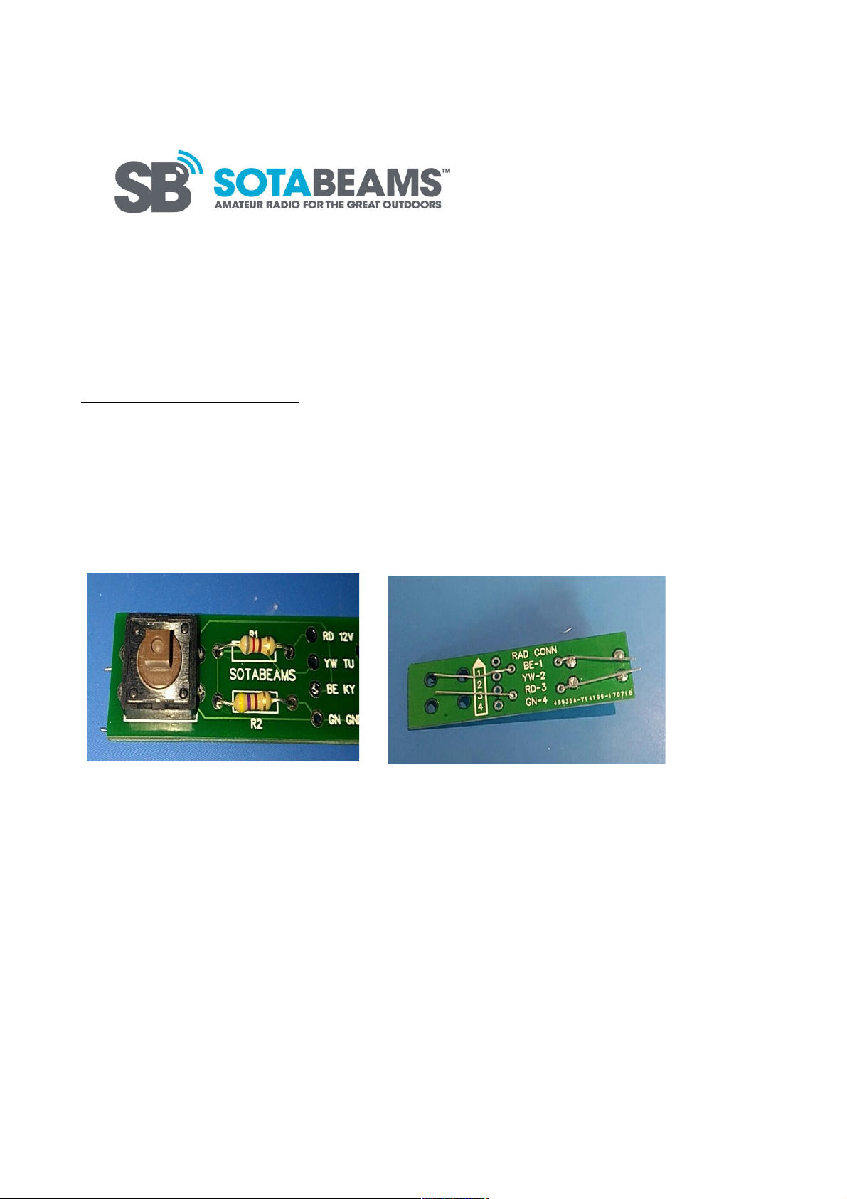
The PCB can be assembled in any order. The switch is to be soldered into the four holes on the
edges of the white box labelled ‘SW1’. The 820R resistor (Grey, Red, Brown, Gold) is to be
soldered into R1 and the 470R resistor (Yellow, Purple, Brown, Gold) into R2. The resistor legs
can be bent on the underside of the board to keep the resistor in position whilst soldering, as
shown below.
2)
The cable must now be stripped in order to solder the red, yellow, blue and green wires to the
board.
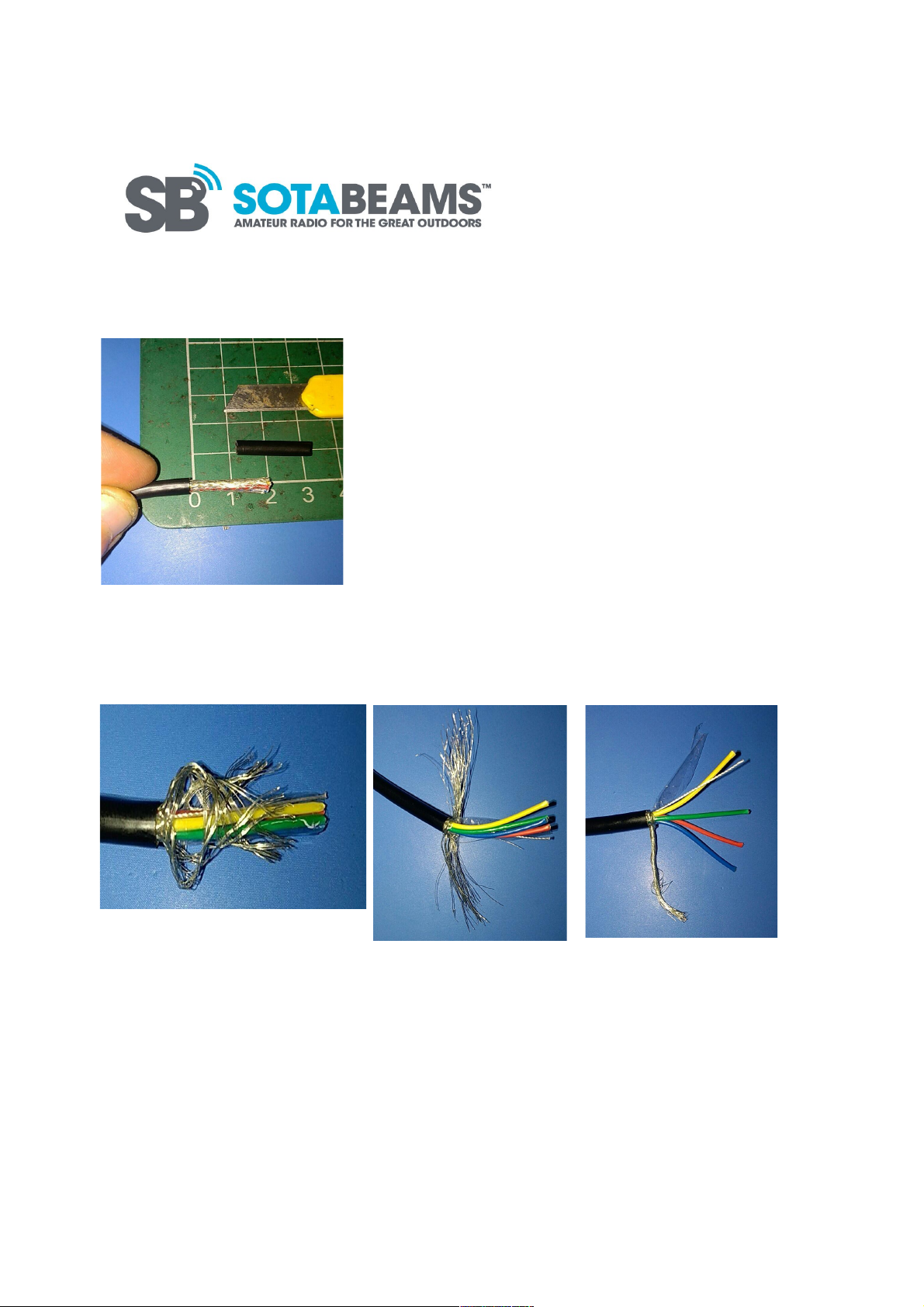
This is best done using a small craft knife. Measure 2cm from the end of the cable and
carefully cut along the circumference of the cable, making sure not to damage the braid
inside. The insulation should slide off easily once cut.
SOTABEAMS last updated 30/08/2017 Page 3 of 12
Page 4
3)
Push the braid back and pick the strands apart using a small screwdriver or tweezers.
Separate the braid into two pieces either side of the wires and then twist the two parts
together as shown below.
4)
Unwrap the wires and cut away the thin plastic wrap and cotton strand. Strip the wires by
roughly 2mm. Tin the ends of the wires and the entire braid.
SOTABEAMS last updated 30/08/2017 Page 4 of 12
Page 5
5)
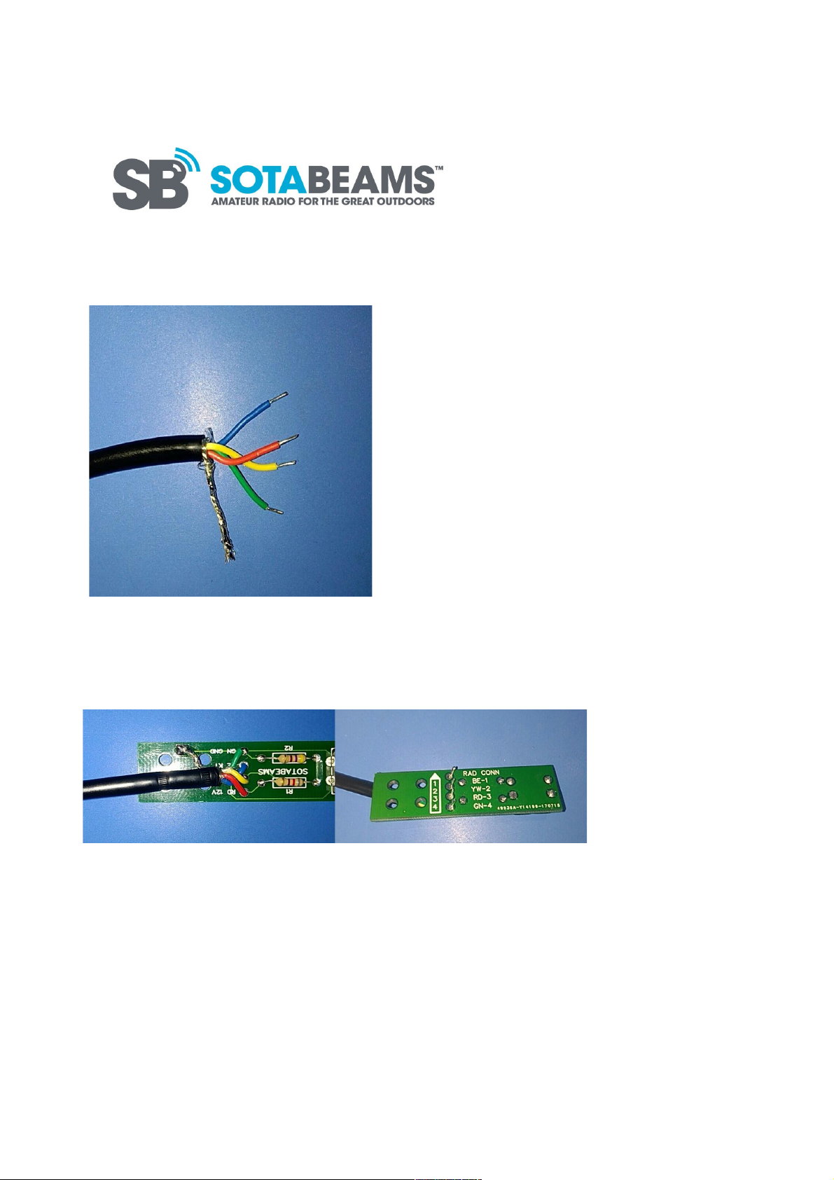
Push the corresponding wires through the holes on the PCB and solder them in place. (1=Red,
2=Yellow, 3=Blue, 4=Green)
Solder the braid to the small silver pad (ground) and trim all excess.
6)
To ensure that the cable does not slip and the joints are firm, there are two holes in the PCB
for the use of cable ties. It is recommended that the head of the cable tie rests on the
underside of the board (as shown) and the tails of the cable ties are trimmed neatly.
SOTABEAMS last updated 30/08/2017 Page 5 of 12
Page 6
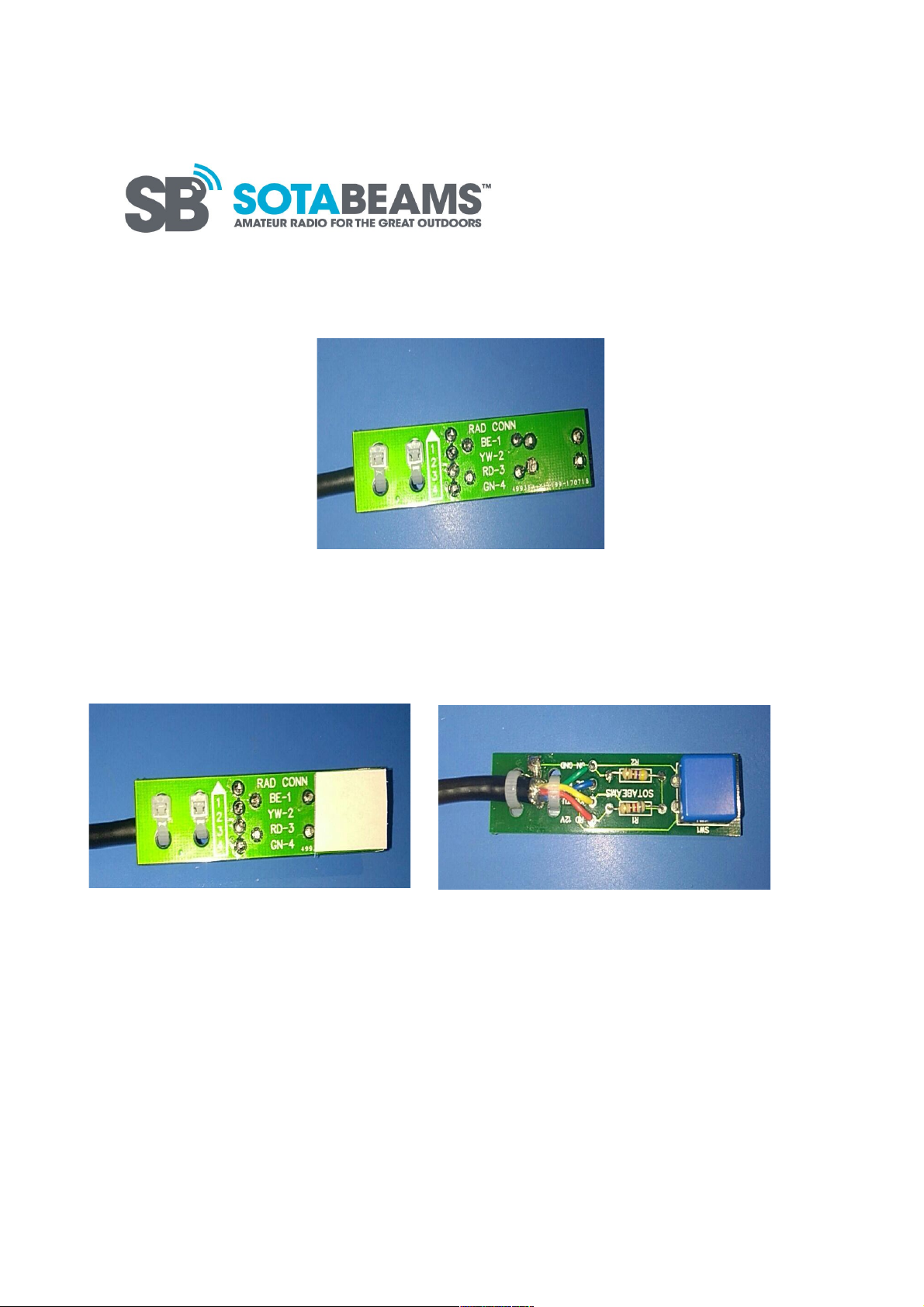
7)
The blue button square can be placed on the button and the small foam pad should be
attached to the underside of the button to cover the solder joints.
8)
The blue heat shrink sleeving can now be slid down the other end of the cable and over the
PCB up to the foam square. A trim with a pair of scissors may be required.
SOTABEAMS last updated 30/08/2017 Page 6 of 12
Page 7
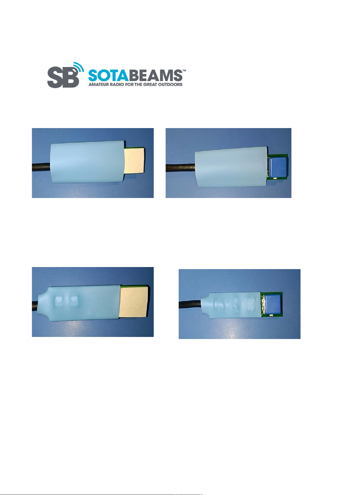
9)
Heat the sleeving until it is gripping all four corners of the PCB, ensuring that it is tight over
the resistors, wires and cable ties.
Your kit will include a SOTAbeams sticker to cover the foam pad.
SOTABEAMS last updated 30/08/2017 Page 7 of 12
Page 8

Joining the connector
1)
The metal contacts in your kit will be attached to one another. The best way to separate them
is using a sharp pair of wire cutters. Cut the ears of the pins as shown in the photograph
below. If the ears are too long they will not fit into the plug, but if they are too short they will
not be secured inside the plug.
2)
Strip the end of the cable 3cm down using a knife. This is a similar process as is used for the
PCB.
Take care to avoid damaging the braid.
SOTABEAMS last updated 30/08/2017 Page 8 of 12
Page 9
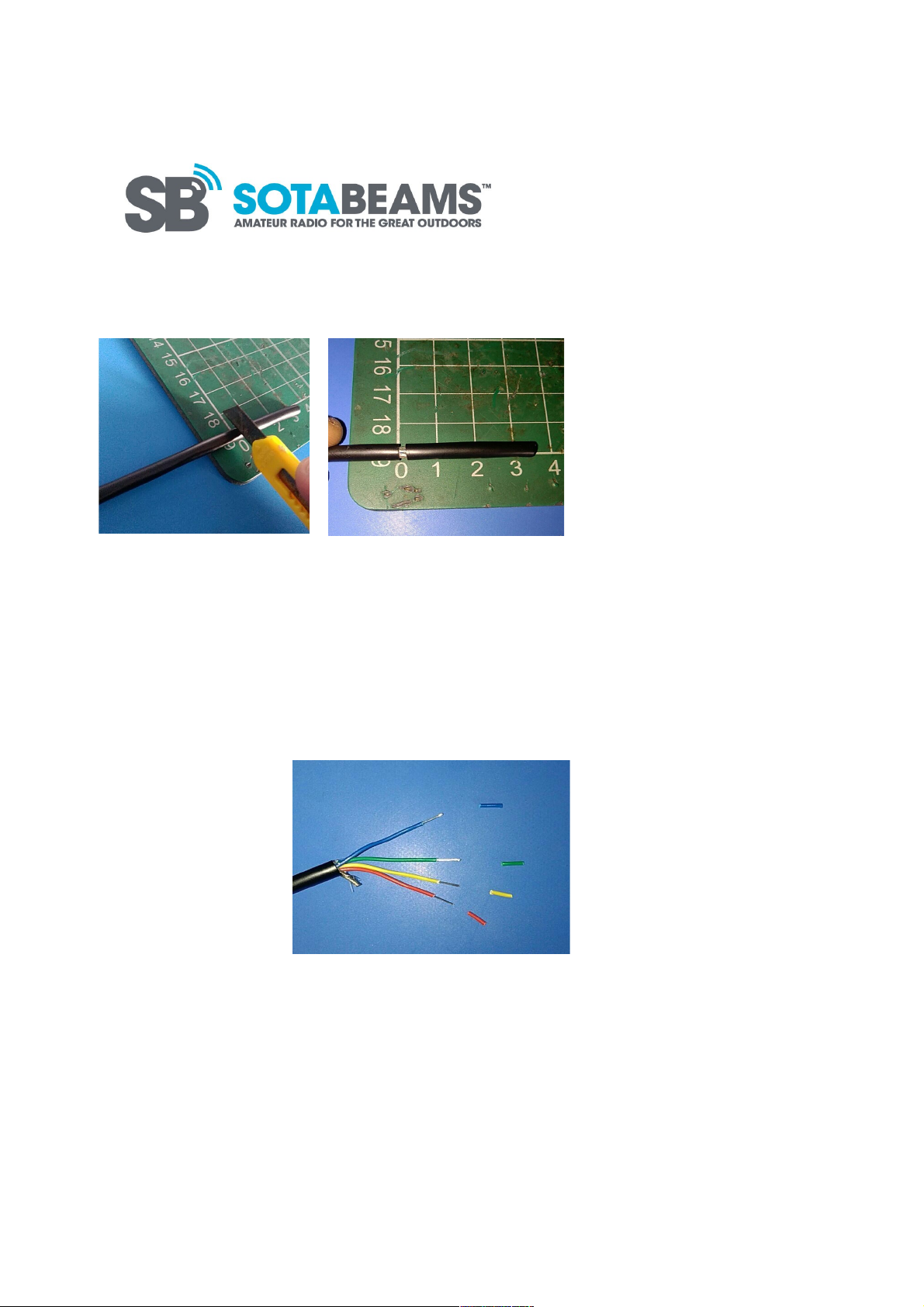
3)
This task requires something small and pointed; I would recommend a small flat-headed
screwdriver or tweezers. Push the braid back on itself and separate the small strands. You
should then twist the braid as shown below. (This is the same process as used in the PCB
assembly)
4)
Slide the red heat shrink onto the cable as this will not be possible later.
Remove the cotton and plastic as before. Trim the braid to 5mm and strip the rest of the wires
by 1cm.
5)
The braid is joined to the green wire using a thin piece of black wire (included in your kit).
Strip one end of the black wire and solder it to the braid. Cut and strip the black wire to an
SOTABEAMS last updated 30/08/2017 Page 9 of 12
Page 10
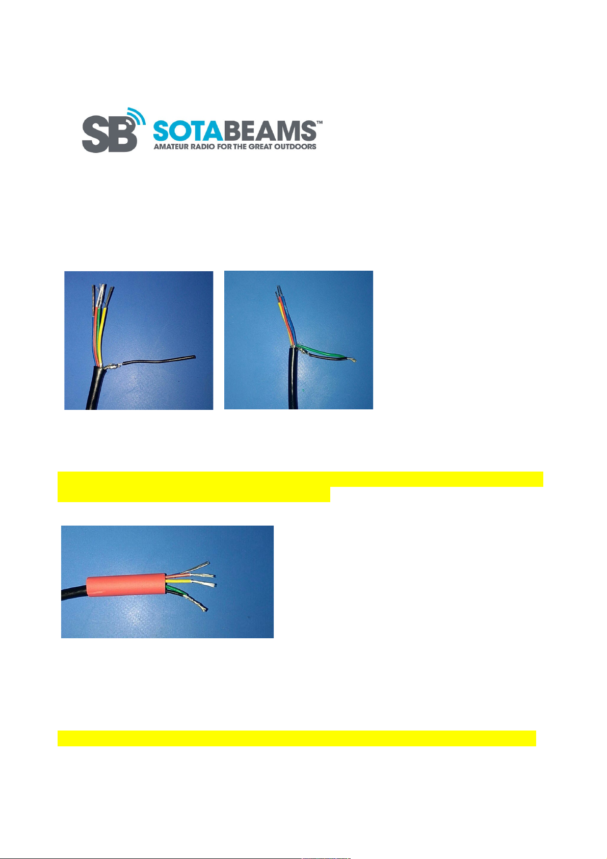
equal length to that of the green wire, then twist them together. Solder this joint and tin the
other wires.
6)
Move the heat shrink so that it covers the solder joint on the braid.
It is important to leave yourself enough room to work with. Also, take into account the order
in which the wires will go into the plastic connector.
(Blue, Yellow, Red, Green)
7)
The connectors are crimped to the wires using a pair of pliers and then soldered to ensure a
strong joint. When crimping the connectors it is best to flatten the long, back parts of the
connectors against the insulation vertically first, and then force them down. This makes the
back part rounded whilst still gripping the wire and allows it to fit into the connector block.
This must be done to all four wires. Ensure that you also solder the wires to the connectors
SOTABEAMS last updated 30/08/2017 Page 10 of 12
Page 11

for the best possible joint.
8)
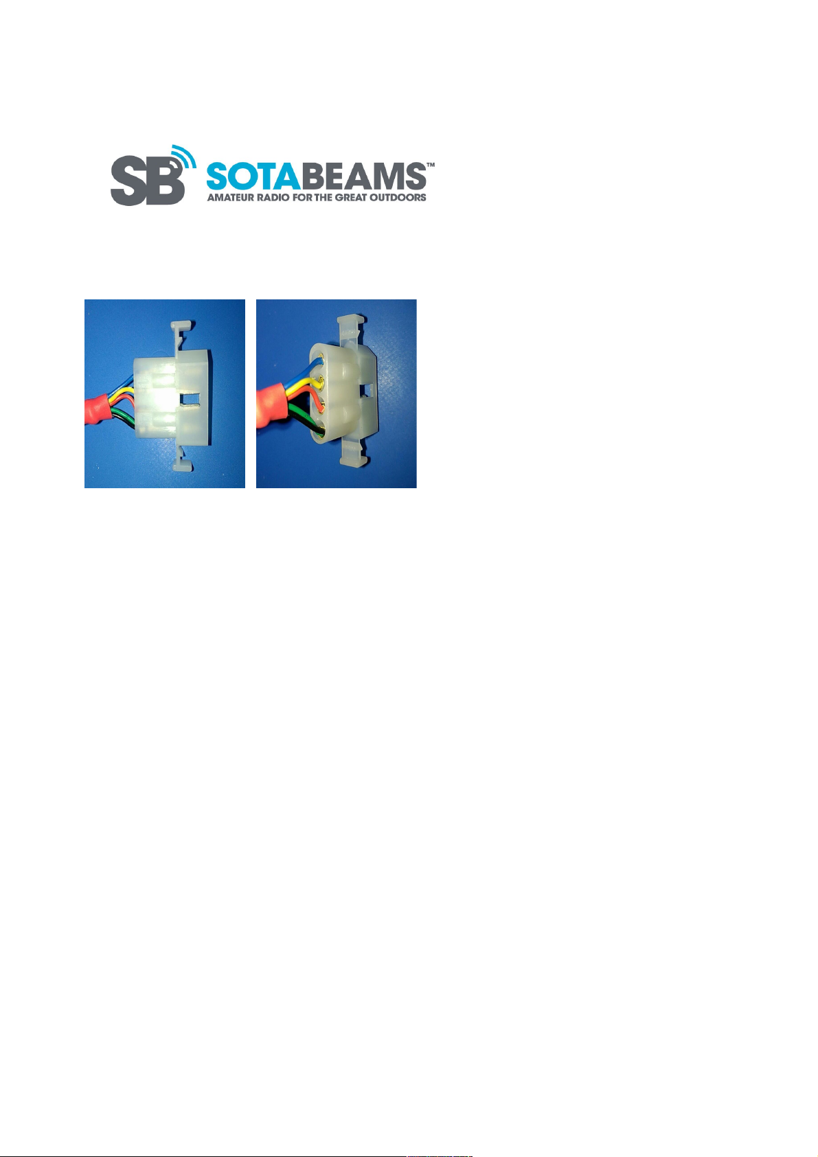
Align all the contacts into their correct positions (Start at the hole closest to the slanted top
of the connector block. This is for the Blue wire, the second hole down is for the Yellow, third
down for Red and the bottom hole is for the Green) before pushing them into the block. You
may not have sufficient space to bend the wires into position individually. Push the contacts
in as far as you can by hand. You may need to use a small screwdriver to push the contacts the
remainder of the way into the block. The back of the metal contacts should be just below the
edge of the plastic holes. (Take extra care to avoid forcing the contacts in too far - this will
render the entire circuit unusable!)
SOTABEAMS last updated 30/08/2017 Page 11 of 12
Page 12
SOTABEAMS last updated 30/08/2017 Page 12 of 12
 Loading...