


sotaturntables@kwom.com - www.sotaturntables.com
JEWEL, SAPPHIRE,
STAR and NOVA Turntables
PLEASE READ THE INSTRUCTIONS COMPLETELY BEFORE BEGINNING SET UP AND OPERATION!
UNPACKING
The SOTA turntable comes bolted to a plywood board, which “floats” in a cardboard sleeve. Begin by
placing the turntable carton on a large, sturdy work surface. Open the box top, fold the box flaps back,
invert the box and lift off. The turntable and the cardboard sleeve will remain on the work surface as you lift
off the outer carton.
Place the turntable and sleeve on edge with the front feet down. Set the following parts aside, which you
will find attached to the bottom of the packing board:
(1) Armboard (Wood, Co mposite or COSMOS with three (3) appropriate mounting screws and hex key
for installation).
(1) 3/32” Hex Key, used for transit set screws and for Wood Armboard screws
(1) Control Panel Cover
(1) Bubble level
(1) Ground Wire
(1) Bag of lead shot, weighing 2 lb. – 14.5 oz . (SAPPHIRE, STAR, and NOVA only. Note: STAR and
NOVA lead shot is packed with pump unit.)
(2) Lead slugs (SAPPHIRE, STAR and NOVA only)
(1) “Dummy” Plug (STAR and NOVA only)
(1) Reflex Clamp (NOVA only)
NOTE: Save ALL the turntable packing materials for re-use, should the turntable
ever need to be shipped.
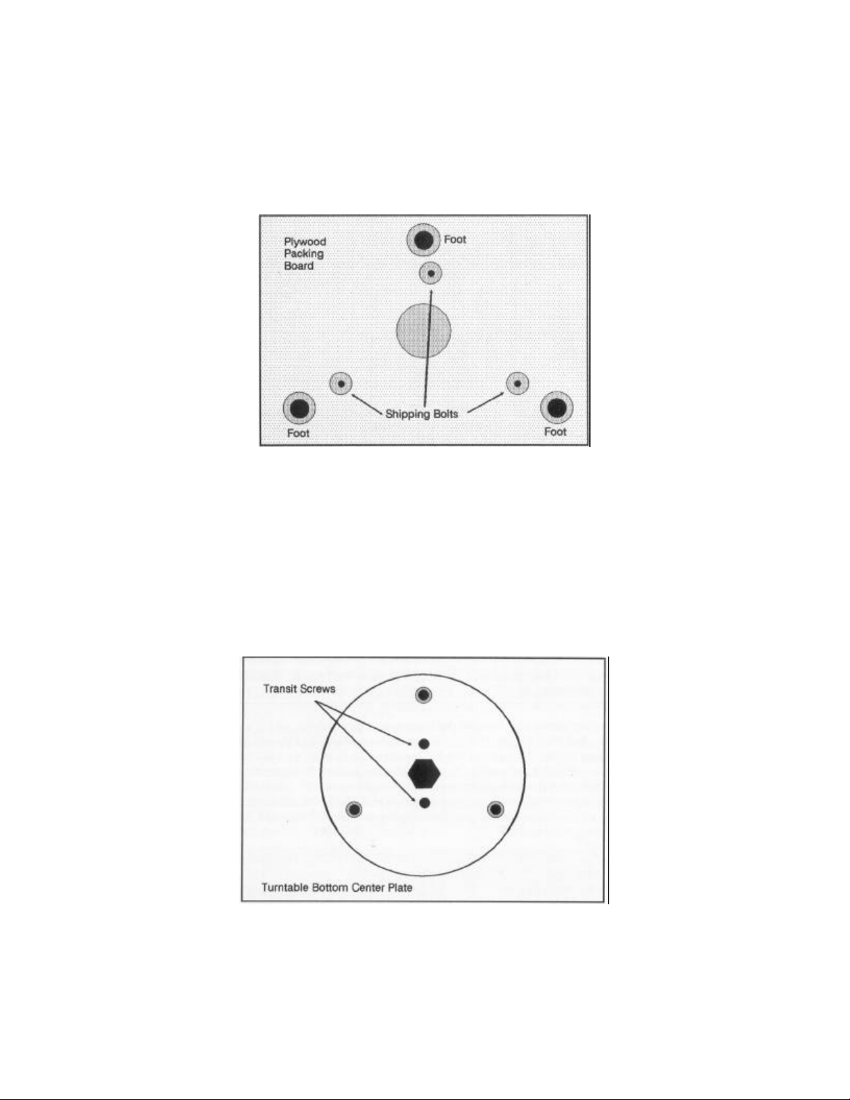
Using a wrench or nut-driver, remove the lower two shipping bolts, which are adjacent to the feet (See
Figure 2). Cut the tape securing the inner sleeve and remove the inner sleeve. Loosen the third shipping
bolt one turn, and gently lower the table with attached packing board back onto its feet. Now, position the
last shipping bolt over the edge of the work surface and remove it. Lift the table from the shipping board
(save the shipping board) and set the turntable on the work surface. Carefully unpeel the plastic wrapping
and save. If included, lift the Dust Cover straight up and off.
For the JEWEL and SAPPHIRE only, remove the power supply from the armboard well and set aside.
Figure 2
Place the turntable on its side with the controls down. Remove the feet and the foam pads. (Save the
foam pads.) Replace the feet, screwing them each in approximately two full turns. Loosen the transit
screw lock nuts, and then using the supplied 3/32” hex key, release (unscrew) one transit set screw – leave
the other in place until the unit is ready to play. Loosen the transit set screw about ¼”, and then use the
transit nut to lock the transit screw in place. (See Figure 3).
Figure 3
2

Put the table on its feet and remove the cardboard shims from under the pulley and the three pads from
around the platter, sliding them out towards the motor. (Save all pads and shims.) Care should be taken
not to disturb the belt. Position the control panel and press in place.
SET UP
STEP 1
(JEWEL only) Place the bubble level on the platter at the mid -point of the cartridge sweep. Adjust the feet
so that the platter is level. At this point the platter should appear parallel to the cabinet. Similarly the
underside of the sub-assembly and the bottom of the cabinet should appear to be parallel. Variations of
3/32” are acceptable. Now proceed to Step 3.
STEP 2
(ALL except JEWEL) Place the bubble level on the platter at the mid -point of the cartridge sweep (see
Figure 4). Place the bag of lead shot upright (vertically) in the armboard well, positioning it to “perch” on
the bar between the arm tube hole and the balancing reservoir. The bag should not make any contact with
the cabinet. Adjust the feet so that the platter is level. At this point the platter should appear parallel to the
cabinet. Similarly the underside of the sub-assembly and the bottom of the cabinet should appear to be
parallel. Variations of up to 3/32” are acceptable. Now remove the bag of lead shot but not the bubble
level.
STEP 3
Attach the tonearm (complete with counterweight, head shell and cartridge) to the armboard and insert the
board into the turntable’s armboard mounting block. On JEWEL only, insert the three armboard mounting
screws, tighten securely using the supplied hex key, and proceed directly to Step 7.
STEP 4
Balance the arm and cartridge approximately. Rotate the tonearm towards the spindle to clear the shot
reservoir. (See Figure 4.) The bubble should be off-center toward s the arm. If it is also biased towards the
REAR, carefully remove the armboard and add one or both of the lead slugs by inserting them into the
holes at the rear of the arm mounting block. (If you need to remove the lead slugs, use the allen wrench
provided to push the slug out from the hole beneath the slug). When the lead slugs have been installed as
needed, replace the armboard assembly with mounting screws, but do not tighten yet.
STEP 5
Place a small paper or styrofoam cup (i.e. very light) on the armboard, being careful to keep it clear of the
cabinet. Rotate the tonearm towards the spindle to allow room for the cup. (See Figure 4.) Pour lead shot
into the cup until the bubble in the level is centered. If the platter is not exactly level, minor adjustments of
3

the feet can be made without affecting the table’s performance. If the platter is still not level, we
recommend repeating the set up procedure.
Figure 4
STEP 6
Now remove the armboard assembly and pour the lead shot from the cup into the shot reservoir. (Note: A
plastic sandwich bag may be used to contain the lead shot in the well, for convenience of later
removal.) Re-insert the armboard assembly into the turntable’s armboard mounting block. Insert the three
armboard mounting screws into the armboard. Support the sub -assembly from beneath the armboard
mounting block and securely tighten the screws using the provided hex key. We suggest you keep all of
the lead shot so that you may combine it and begin again if you ever change tonearms.
STEP 7
Slightly raise the cabinet and release the final transit set screw approximately ¼” using the 3/32” hex key.
Secure the transit set screw in the down position by tightening the transit nut.
Caution: The Sapphire bearing assembly is now unprotected. Handle with extreme
care when moving. The table may be carried from room to room but should be place
down gently. Do not ship by car or truck with the transit setscrews in the down
position. This constitutes mishandling and is not covered by the warranty.
STEP 8
Position the turntable in its place of operation. Using the bubble level on the platter, adjust the feet so that
the platter is level. (Take care not to over tighten the feet to the extent that the threaded leg pushes
through or deforms the bottom of the rubber foot.) Always use the platter for the reference, the cabinet
level is secondary. The turntable can be grounded via the grounding post on turntable bottom using the
supplied ground wire. Final tonearm balancing can now be performed.
4

This completes the set up procedures. If included, the optional Dust Cover can now be mounted.
CAUTION: Lead leaves an unhealthy film when handled directly. Wash hands with
soap and water after every contact. Keep lead shot out of children’s reach.
HOOK UP and OPERATION
JEWEL and SAPPHIRE only
Plug the gray DC power cord from the turntable into the jack on the small black power supply box. Plug the
power supply box into an AC outlet, switch the power supply on and locate in a position well away from
tonearm cables and pre-amp.
On SAPPHIRE only, remove the wood control cover, turn on the turntable and verify that the belt runs
parallel to the cabinet surface and is centered on the pulley. If it does not, repeat set up procedure.
Check the speed with the enclosed strobe disk. Any bright AC light source may be used for this procedure.
Fluorescent is most effective. To adjust speed accuracy, use the speed knob for the selected speed
setting. The speed has been set at the factory but minor shifts may occur during shipping. The range of
adjustments is about 3%. If you are not able to get the speed properly set, check to see that the platter
spins freely. If the platter does not move freely it may be that the transit set screws are not fully released.
Loosen each transit set screw an additional ¼” and lock in position with the transit screw nuts.
STAR and NOVA only
The STAR and NOVA are powered from the vacuum pump/power supply unit. This unit is controlled from
the turntable via the multi -conductor cable from the table, using the turntable’s on/off switch. There are no
controls on the pump/power supply unit itself, so it can be located in a remote spot. A twelve-foot cable has
been provided to allow flexibility in choosing a location. The pump should be placed in a non-resonant
location, ideally a carpeted floor or on a foam pad on the floor. If placed too near a pre-amp, induced hum
may occur; if placed on a hard shelf, vibration may be audible.
When in place, plug the cord from the turntable into the pump/power supply unit and tighten securely.
Locate the length of vacuum hose enclosed with the pump/power supply unit. Connect the end with the
screw-on hose coupler to the vacuum fitting on the pump/power supply unit and tighten securely. The other
end of the hose attaches to the vacuum nipple on the underside of the turntable at the platter’s center bolt.
Make sure that both ends of the vacuum hose are securely attached, and the hose is not crimped or
pinched. Now plug the power supply’s power cord into an AC outlet. Remove the wood control cover, turn
on the turntable and verify that the belt runs parallel to the cabinet surface and dead center on the pulley. If
it does not, repeat the set up procedure.
Check the sp eed with the speed with the enclosed strobe disk. Any bright AC light source may be used for
this procedure. Fluorescent is most effective. To adjust speed accuracy, use the speed knob for the
selected speed setting. The speed has been set at the factory but minor shifts may occur during shipping.
5

The range of adjustment is about 3%. If you are not able to get the speed properly set, check to see that
the platter spins freely. If the platter does not move freely it may be that the transit set screws are not fully
released. Loosen each transit set screw an additional ¼” and lock in position with the transit set screw
nuts.
Place a record on the platter and secure the clamp over the spindle. Switch the table on. You will notice
that initially the pump runs quite hard (and may be audible) before switching automatically to the
“maintenance” mode after a seal has been achieved. This is normal. In this maintenance mode the pump
noise should be minimal, if audible at all. A seal is normally achieved within 10-30 seconds. The best
visual way to tell if a seal has been achieved is to observe the vacuum lip on the outside edge of the
platter. Before the record is vacuum clamped, the lip will angle up, rising above the top surface of the
record. Once the record is fully sealed, the vacuum lip will appear flat and parallel to the record’s surface.
If in doubt, gently tap the upper surface of the record with your fingertip (avoiding the finger nail). You
should hear a solid thud. If you hear a rattle from the record hitting the mat, you have not achieved vacuum
seal. (For tips on vacuum system use and maintenance, see the sections titled General Hints For Best
Results and Vacuum System Trouble Shooting, below.)
To set the initial arm height accurately, the vacuum must be on and the record vacuum-clamped. To
facilitate this procedure, we have provided a “dummy” plug to allow running the vacuum pump without
turning on the turntable’s motor. Simply remove the multi -conductor cable attached to the pump/power
supply and in its place insert the included dummy plug. The pump will begin operating as soon as the
dummy plug is inserted and screwed in tight. When the tonearm height is set, remove the dummy plug and
re-install the turntable’s connecting cable.
SOTA Sales & Service Center
10830 S. Nagle, P.O. Box 247
Worth, Illinois 60482 USA
www.sotaturntables.com
sotaturntables@kwom.com
800- 772-SOTA
6

Removal of Platter
Initial Procedure
It is advisable to remove tonearm/armboard assembly and lead shot/slugs (if any) before
removing the platter to prevent damage, but this is not required for assembly. If not removed,
make sure to secure the arm to its arm-post, and place the stylus guard over the cartridge. We
suggest you move the turntable to a large work area where you can place the turntable on a
sturdy, flat working surface. For easiest platter removal and re-installation, we suggest the use of
two chairs used to support each side, providing easy access to platter mounting hardware on
bottom of the turntable.
Removal of Platter
Preparation
Remove mat if it is removable (older models only). Remove the motor control panel (lift off
wood cover, or use 5/64” Allen Key on older models to remove metal control cover and black
bezel underneath) and the drive belt. The platter may now be removed, as follows:
Step 1:
Gently turn the cabinet on it side so that left side is down flush with working surface (that is, the
motor side becomes the base). The assistance of a second person, to steady the turntable, is
recommended. Tighten (screw UP, towards turntable top) the two transit screws with the 3/32”
Allen key until they stop (do not over-tighten). Now remove the locking nut from each transit
screw and set aside. The turntable should now be placed on the two chairs, to allow easy access
to the bottom and top for platter removal.
Step 2:
Using 1/2” socket or wrench, remove the center-retaining bolt. On newer tables, using the 5/32”
Allen Key also remove the three hex socket cap screws holding the platter retaining plate in
place, and remove the plate. Save all the hardware for re-installing the platter after the new
motor is installed. You should now return the turntable to your work surface.
Step 3:
Important: At all times insure that the heavy platter cannot fall and damage the turntable,
your working surface, or your fingers.
Working from the top now, extract platter by easing it away from the sub -assembly. The easiest
way to do this is by using your SOTA clamp. Simply clamp onto the spindle and lift up. You
may need to rock the platter back and forth slightly to free it from the sub -chassis. Take great
care not to damage the edge of the platter cut out with the underside of the platter, causing
chipping or scratching.
 Loading...