

Page 1
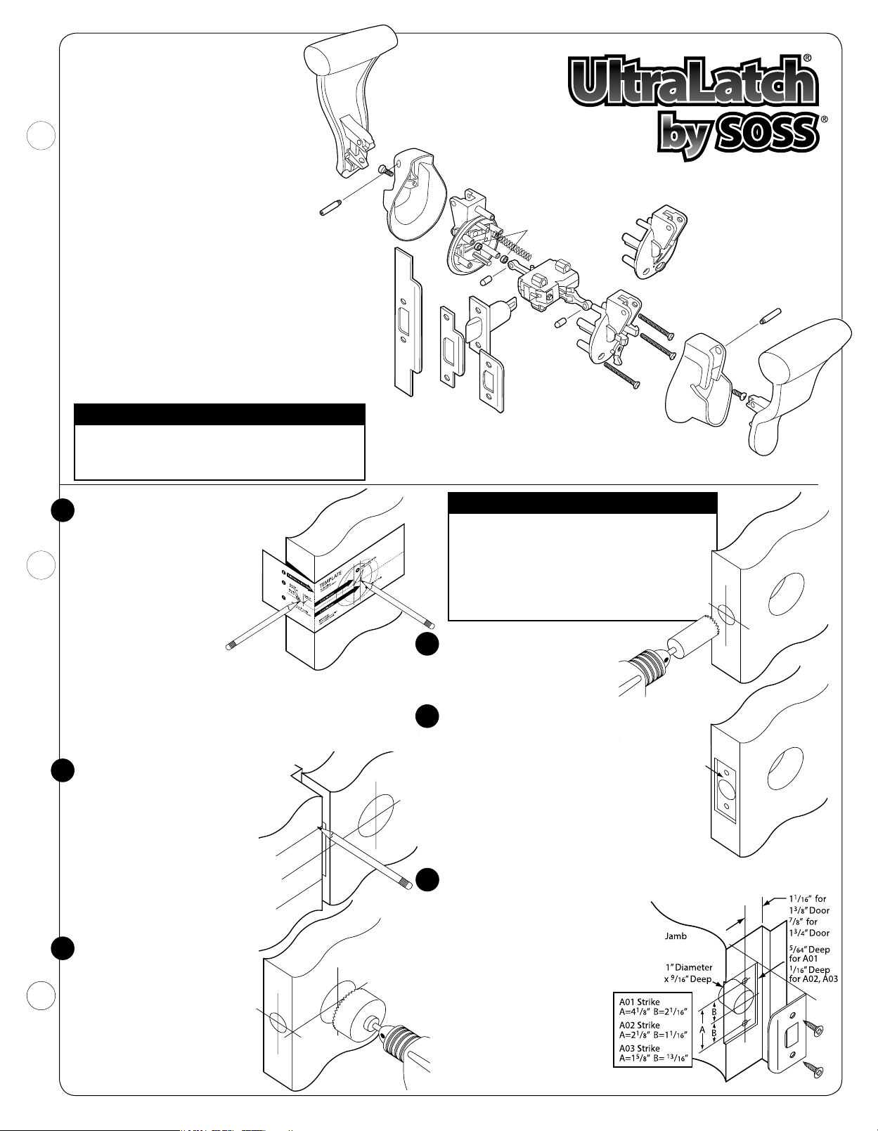
Before installation, please check
carton contents:
•BoltAssembly:Includes2Mounting
Screws and 2 Face Plates 1" and 1
•Unirose/ChassisAssembly:Includes
Mounting Hardware, Lock Trip Key
•2Handles:1Leftand1Right
•2RoseCovers
•StrikePlates:L1Modelwillinclude
1
1
/8" x 23/4" and 11/4" x 21/4" Strike Plates
L2 and L3 Models will include 1
1
1
/8" x 23/4" and 11/4" x 21/4" Strike Plates
1
/8"
1
/4" x 47/8",
Handle
Left
Pivot Pin
Cover
Screw
Tools needed to install
the SOSS® UltraLatch®
•FlatScrewdriver •T-156-LobeScrewdriver
•TorpedoLevel •#2Sq.DriveScrewdriver(Robrtsn)
•AdjustableSquare (Onlyneededifconvertingfrom
•1”FlatWoodChisel LHtoRHdoororientation)
•Pencil •ElectricDrill
•UltraLatchDrillGuide •
•Hammer •SmallNeedleNosePliers
•#2PhillipsScrewdriver •SafetyGogglesorGlasses
Important Notes
Please DO NOT remove factory lubrication.
DO NOT remove the Linear-Cam shipping pin until
instructed to do so.
1
/8", 11/64" and 9/32" Drill Bits
A01
(ANSI)
Unirose
Cover
Handle
Shaft
A02
Strike Plates
Push Side
Unirose
Spacers
(2" doors only)
Spring
Chassis
Handle
Shaft
Bolt
Assembly
A03
UltraLatch® is ANSI grade-1 certified
when used with the included ANSI
(A01) strike plate.
Installation Instructions
Models L1, L2, L3
Optional UltraLatch®
Drill Guide (Part # LDG)
(Sold Separately)
Pull Side
Unirose
Screws
Unirose
Cover
Pivot Pin
Cover
Screw
Handle
Right
Door Preparation
1
For new slab door, start at
least 36" above floor.
Mark from
High Side of
Door Bevel
Fold and apply template to
high side of door bevel.
Ensure that template is level
and square.
Mark center hole on door face
through guide on template
3
for 2
/8" or 23/4" backset.
Repeat on door edge for latch.
With template in place, transfer center line to door jamb.
UltraLatch® units are packed to a specific backset (2
3
2
/4") depending upon door thickness. Normally If your door
3
is 1
/8" thick, you will have a 23/8" backset; if your door is 13/4"
or thicker, the backset is 2
To determine position for strike plate,
2
3
/4".
ensure that center of hole is level with
center of 2
1
/8" face hole on door.
Jamb
To measure, insert end of
template against flat of latch
bolt and close door against stop.
Mark template from edge of jamb
and transfer lines around face of
jamb to locate strike opening.
Mark center line for screws and
1" hole.
1
Drill 2
3
/8" hole through door face
as marked for lockset. Hole must
be drilled perpendicular to the
door face and level. Drill the 2
1
/8"
hole first. To avoid splintering,
stop when pilot bit starts to exit
opposite side. Reverse drill to
remove and repeat on opposite
side using pilot hole as a guide.
3
/8" or
Door
21/8” Face Hole
Important Notes
If you are prepping the door for a standard
round deadbolt, leave at least 8" between the
center of deadbolt and center of UltraLatch®
bolt to allow clearance for UltraLatch® handles.
5
If using any other type of deadbolt, measure
before placing hole to ensure that you have
enough clearance.
Use 1” hole saw to drill door edge
4
1” Edge
Hole
2" deep. Hole must be drilled
parallel to the door face and
perpendicular to door edge.
It is very important that the bolt assembly is flush
5
in the mortise. If the door is beveled, ensure that
the bolt assembly is flush with the low
side of the bevel. The barrel of the bolt
must be parallel to the door face and
Mortise
5
/32”
Deep
Door
perpendicular to door edge. Trace with
pencil or utility knife to outline mortise.
Mortise edge of door to accept bolt assembly
and face plate.
Insert bolt and tighten screws.
Drill door jamb using 1” hole saw 9/16" deep in door jamb on center line
6
of screws.
Locate screw holes on strike with
center line on jamb. Outline edges and
chisel 5/64" deep for A01 (ANSI) strike
plate and
Predrill
or
1
/16" deep for A02 and A03.
11
/64" pilot holes for A01 (ANSI)
1
/8" pilot holes for A02 or A03
strike plates.
Install strike plate and
tighten screws.
Adjustable tang on A03 strike
plate permits bending to
eliminate loose fit between
door and stop.
1
Page 2
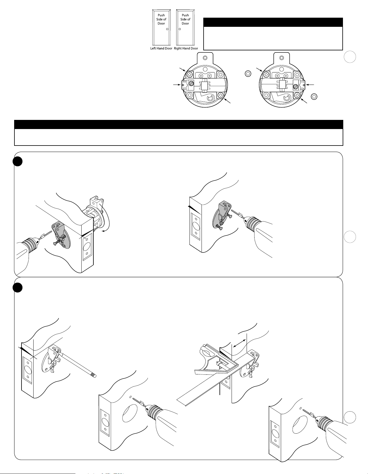
Determining Door Orientation
y
Before installing the Unirose/Chassis Assembly you must
determine if your door is a Right or Left hand door. This is
accomplished by noticing hinge location when facing the
Push side of the door. If the hinges are on the left, it's a left
hand door and if on the right, it's a right hand door. The
Important Notes
DO NOT use power tools to secure screws.
DO NOT remove lubrication from internal parts.
DO NOT remove linear cam shipping pin until told to do so.
assembly is set at the factory for a left hand door.
2” Doors Only
Screw at
4 O’clock
Screw at
10 O’clock
Spacer for
Unirose Set Up for
Right Hand Door (Chassis Rotated 180°)
Chassis faces
3 O’clock Position
2” Doors Only
Screw at
4 O’clock
Spacer for
Set Up for a Right Hand Door
Remove the 2 screws that secure the chassis to the Push
Unirose using a #2 Square Drive Screwdriver. Rotate the
Chassis 180° so that the Linear Cam now faces the 3 o'clock
position (as shown). Reinstall and tighten the screws at the
4 and 10 O'clock positions. If this is a 2" door installation
(L3) then you must also reinstall the Spacers between the
Chassis and Unirose at the 4 and 10 o'clock positions.
Screw at
10 O’clock
Chassis faces
9 O’clock Position
Unirose Set Up for
Left Hand Door (Factor
Setup)
Important Note
The UltraLatch® requires a precisely located screw hole drilled perpendicular to the door face above the face hole. Follow instructions in 7 or 7a below to
locate this hole. We highly recommend the purchase of the optional UltraLatch® drill guide to ensure proper location of this hole.
Installation using Optional UltraLatch® Drill Guide
7
Prepare
penetration for 1
9
/32" drill bit by marking a stop-mark with tape to allow 2” max
3
/4" and 2" thick doors or 15/8" for 13/8" thick doors.
Measurement should be made from tip of drill to tape marker.
Open Chassis Assembly, remove the 3 screws from Pull Side Unirose.
Invert Unirose to
Tape Stop-Mark
Level Line
UltraLatch
Drill Guide
Invert Unirose
before drilling to
avoid damaging
Unirose.
avoid drilling into it
and place in the 2
face hole on door.
Insert UltraLatch®
Drill Guide on other
side of door, attach
with 2 lower screws
to snug.
Push Side
Check with Torpedo
Level only if door is
plumb – adjust
if necessary.
Installation without Drill Guide
7a
If not using Drill Guide, prepare 9/32" Drill Bit by marking a Stop-Mark
with tape to allow 1" max penetration for 1
door or 1
5
/8" for 2" Door. Measurement should be made from tip of
3
/8" door, 13/8" for 13/4"
drill to tape marker.
Open Chassis Assembly, remove the
3 screws from Pull Side Unirose.
As long as door is plumb, insert Pull
Pull Side
Unirose
Side Unirose into the 2-1/8” hole.
Check measurements and mark
location of
9
/32" hole with a pencil.
Remove Unirose and repeat
procedure on opposite side of door.
Carefully drill hole, insuring the
Tape Stop-Mark
bit is perpendicular to the door
face. Do not drill completely
through the door. Drilling in two
steps will prevent splintering on
the door.
When holes meet, go to step 8.
If door is not plumb, use measurements as noted in #7a.
When level, tighten screws.
DO NOT USE POWER
TOOLS TO SECURE SCREWS
We recommend drilling
the push side of the door
first. Drill hole through Drill
Guide to the tape mark. Do
not drill completely through
the door. Remove drill
1
/8"
UltraLatch
Drill Guide
Tape Stop-Mark
guide and Unirose, repeat
procedure on opposite side
Pull Side
of door. Drilling in two steps
will prevent splintering on
the door.
When holes meet, go to
step 8.
To save time, we recommend using 2 UltraLatch® Drill Guides.
Please refer to section 12 on page 4.
If not using Drill Guide or Level
Many doors are beveled on the edge. Be sure to start measurement
from the highest point of the bevel when using an adjustable square.
Prepare
max. penetration for 1
9
/32" Drill Bit by marking a Stop-Mark with tape to allow 1"
3
/8" door, 13/8" for 13/4" door or 15/8" for 2"
Door. Measurement should be made from tip of drill to tape marker.
Optionally, you can use
an adjustable square to
determine position for the
Unirose. If your backset is
3
2
/4", set square to 223/64"
from outside of door to the
Pull Side
top side of the Unirose.
Unirose
Mark your drill hole with
Measure
from high
side of door
bevel
23/4” Backset = 223/64”
3
/8” Backset = 131/32”
2
pencil, repeat on other side.
If your door has a 2
backset, the distance
needed is 1
31
/32".
Tape Stop-Mark
Carefully drill hole, insuring the bit
is perpendicular to the door face.
Do not drill completely through the
door. Drilling in two steps will prevent
splintering on the door.
When holes meet, go to step 8.
3
/8"
2
Page 3
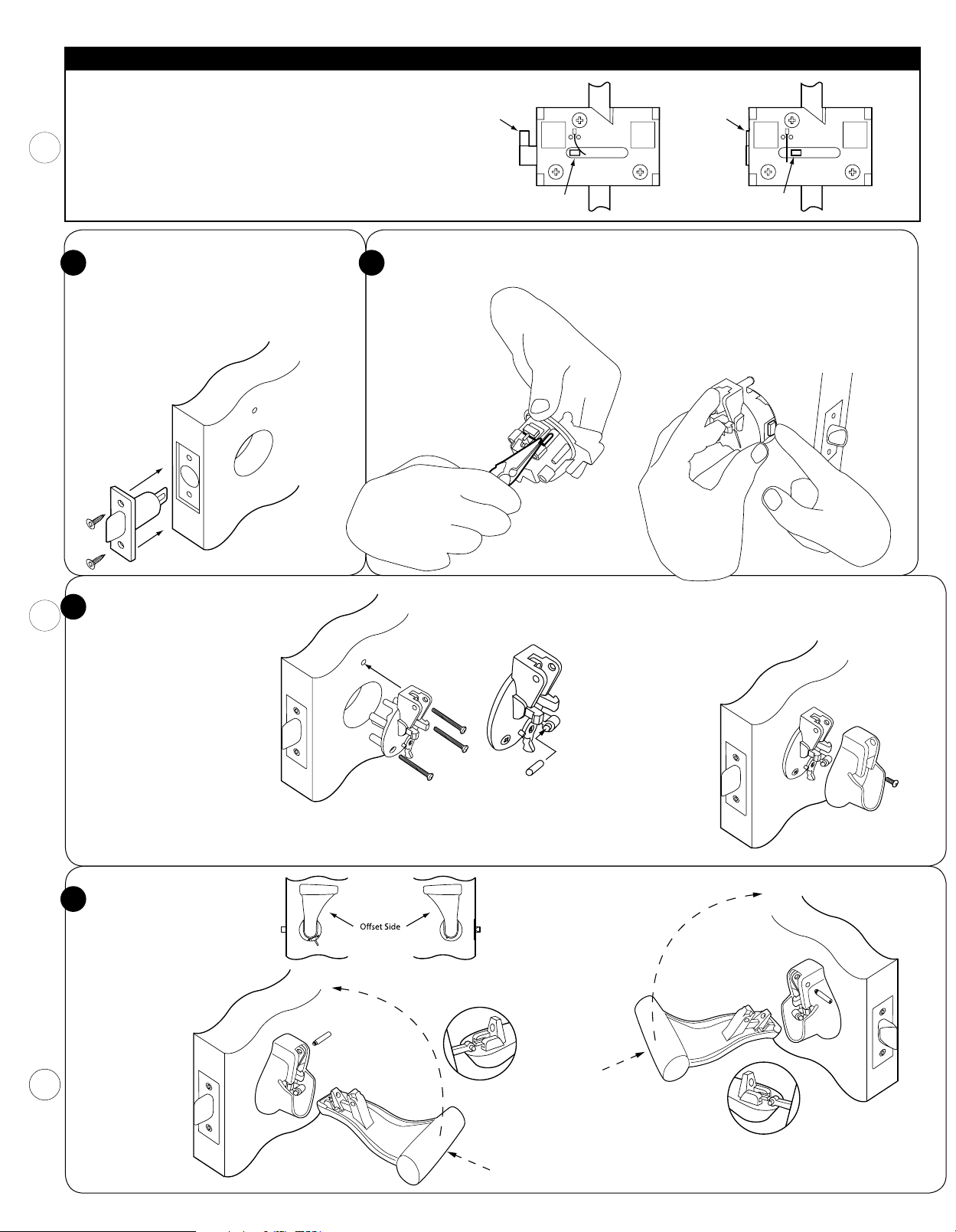
Important Note
Do not actuate the Linear-Cam by pushing it in or by actuating the
Racks.
The Linear Cam must be in the forward position to be installed.
If by accident you have done so, then you must reposition the
Chassis Spring as shown at right using needle nose pliers or a small,
flat blade screwdriver.
Chassis Assembly
Pin
Correct, Ready to InstallIncorrect, Not Ready to Install
Pin Retracted
Install Bolt Assembly
8 9
Install bolt assembly through outside
edge of door. Tapered end of bolt should
face the strike plate in the jamb. Attach
face plate (1" or 1
assembly short shell.
Attach with screws.
Attach Pull Side Unirose
10
Secure with 3 screws to snug.
Test bolt action again. Check
for level with Torpedo Level,
if correct, tighten the screws
with #2 Phillips screwdriver. If
your UltraLatch® is equipped
with a Privacy Lock, the lever
will be facing the right. Turn
the locking shaft on the Push
side to the right (Clockwise).
(To test the bolt, on the PULL
SIDE of door, push the rack,
on the PUSH SIDE of the door,
pull rack to test).
1
/8"), snap on to bolt
Installation of Chassis Assembly
Remove Linear Cam Shipping pin
with yellow flag
from Unirose
with needle
nose pliers.
Remove the following from your Hardware Bag: 2 each of the Handle
Pivot Screws, 2 each of the Handle Shaft and 2 each of the Cover Screws.
Insert Push Side Unirose into door, slightly
depressing the linear cam to clear the 2
When Push Side is approximately
of door, push bolt inwards to depress retention
clip, allowing linear cam to engage into slot
in bolt. It should click into place with the Bolt
Assembly. Manually test to ensure bolt action
works freely.
Install Handle Shafts into racks.
Make sure they are centered
on each side.
Install Rose Covers
w/cover screws.
1
/8" hole.
1
/4" from face
Install Handles
11
When installing handles, the
offset side of the handle must
face the hinge side of the door
(see diagram at right).
Install PUSH SIDE
Handle. Place
handle almost
flat sliding over
handle shaft.
Tip forward,
insert Pivot Pin
and tighten with
T-15 6-Lobe
Screwdriver.
Repeat procedure on
the PULL Side handle
Handle Pivot Pins
come with thread
locking material
preapplied.
We recommend
a 72 hour period
before excessive
use of door,
to allow
thread locking
material to cure.
Test to ensure system works freely.
Congratulations, your installation is complete!
3
Page 4
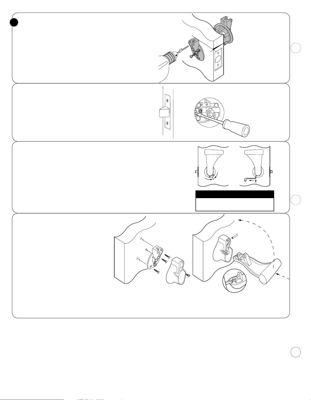
Using Two UltraLatch® Drill Guides
12
Prepare
maximum penetration for 1
9
/32" drill bit by marking a stop mark with tape to allow 2”
3
/4" or 2" doors or 15/8" for 13/8" thick doors.
Measurement should be made from tip of drill bit to the tape marker.
Insert UltraLatch® Drill Guide into 2
1
/8" hole on the Push Side of the
door, insert screws to align for second Drill Guide on Pull Side of door.
Tighten screws slightly, check with torpedo level to ensure that Drill
Guides are level. If both sides are level, tighten screws and recheck for
level. Adjust if necessary. Drill first hole from the Push-Side of the door,
then go to the Pull-Side and drill until the holes meet.
If Latch Disassembly from Door is Required.
Remove Pull Side handle, cover and Unirose by removing the three
screws. Depress spring clip while gently pulling on the Push Side
Unirose to free bolt to allow removal. While removing assembly,
depress clip from Pull Side, depress rack slightly to allow clearance for
the one inch hole.
Before attempting to reinstall, reset the Chassis Spring as shown on
the top of page 3.
About the Privacy Lock
The Privacy Lock on the SOSS® UltraLatch® will secure your door from the inside
(Pull Side) of the room. Slide lever to the LEFT to activate.
Operating the Pull Side handle will disengage the Privacy Lock.
For instructions on how to configure the Privacy Lock on the push side of the
door, please see change over instructions insert or contact the factory.
A Trip Key is provided. To deactivate the Privacy Lock from outside of door, insert
Trip Key into small hole on the Unirose Cover. For LH Doors pull slightly toward
the hinge side of the door. For RH doors push key toward the door jamb.
For added security, use the SOSS® Single Cylinder Deadbolt by Medeco.
(See separate installation instructions).
Tape Stop-Mark
UltraLatch
Drill Guide
UltraLatch
Drill Guide
Push Side
Using 2 UltraLatch® Drill
Guides will save set-up time.
Trip Key
Important Note
Both handles must be installed before
activating the Privacy Lock.
For Bifold Closet Doors
Additional Tools needed:
1
/8" Drill bit
If installing UltraLatch® on bi-fold closet door,
please use the following procedure.
If other UltraLatch® handles are used in the
room, try to match height for consistency.
Please follow Door manufacturer's instructions
for location of the handles.
Determine the best distance from the door’s
edge to install the handle.
1
No 2
/8" hole is necessary. Once your placement
is determined, place Closet Unirose on face of
door, check for level, then mark for screw holes.
Pre-drill to
7
/8" depth with 1/8" drill bit.
Attach Closet Unirose with the provided screws.
Attach rose cover and handle as directed in
step 10 and 11 of basic instructions.
Tip:
Mark top hole at 12 o'clock. Drill pilot hole and attach with screw to snug,
check for level. Mark other screw holes with pencil. Loosen Unirose and
rotate 180°. Drill other pilot holes. Return Unirose to original position and
install remaining screws.
May be covered by one or more U.S. Patent Nos. 7,950,703; D603,244:, D600,531; D592,486; D584,594 and D502,641. Other Patents Pending.
®
SOSS
Door Hardware
UltraLatch® is made in the U.S.A. of domestic and imported components.
Universal Industrial Products, Inc.
Phone: (419) 737-2324 (800) 922-6957
Email: [email protected] Internet: www.soss.com
One Coreway Drive
Pioneer, OH, USA 43554-0628
FAX: (419) 737-2130
Part #: LPUXAY2 © Copyright 2016, Universal Industrial Products, Inc.
4
 Loading...