

Page 1
Service Manual
SORVALL
TC6
Parts Section
Updated March '02
IMPORTANT INFORMATION REGARDING USE OF THIS MANUAL
READ BEFORE USING
This manual provides technical information for the proper servicing of the product(s) specified. This manual is
intended only for use by Sorvall Service personnel, or by qualified technicians who have been trained by Sorvall
in the safe, proper servicing of that product.
This manual has been designed as a supplement to training, not a substitute for training; servicing should not
be attempted by untrained personnel. Technicians who have not been trained by Sorvall are not familiar with the
product design or the hazards that may be encountered during servicing. In addition, lack of training can result
in faulty repair – possibly making subsequent product use dangerous, or product yields unreliable.
Although content of this manual is believed to be adequate for its intended use, Sorvall makes no representation or warranty regarding completeness, adequacy or otherwise (not even as a supplement to a given training
course) and assumes no obligation or liability. In the event a qualified, trained technician is unable to repair the
product using this manual, Sorvall Technical Service should be contacted for additional guidance.
Page 2

OPERATING
INSTRUCTIONS
SORVALL TC6
Tabletop
Centrifuge
Sorvall Products, L.P.
Newtown, Connecticut
U.S.A.
PN 78006-1
Issued August 1996
Page 3

Table of Contents
This manual is a guide for service of the
SORVALL Centrifuges
SORVALL TC6 Tabletop Centrifuge
Data herein has been verified and validated and is believed adequate for the intended use of the
centrifuge. Because failure to follow the recommendations set forth in this manual could produce
personal injury or property damage, always follow the recommendations set forth herein. Sorvall does
not guarantee results and assumes no obligation for the performance of rotors or other products that are
not used in accordance with the instructions provided. This publication is not a license to operate under,
nor a recommendation to infringe upon, any process patents.
This service manual is intended as a service aid. While the manual is kept current and includes
information regarding significant design changes, specific designs may still vary from centrifuge to
centrifuge.
This service manual is intended for use only by service personnel who have been trained by Du␣Pont.
Due to the high electrical potential in this centrifuge, untrained individuals must not attempt any of the
procedures in this service manual.
WARNINGS, CAUTIONS, and NOTES within the text of this manual are used to emphasize important
and critical instructions:
WARNING
: A Warning informs the operator of a hazard or an unsafe practice that could result in
personal injury, affect the operator's health, or contaminate the environment.
CAUTION:
NOTE:
A Caution informs the operator of an unsafe practice that could result in damage of
equipment.
A Note highlights essential information.
W A R N I N G
!
When using radioactive, toxic, or pathogenic material, be aware of all characteristics of the material and
the hazards associated with it. In the event that leakage or rotor failure occurs, neither the centrifuge nor the rotor
can protect you from the particles dispersed into the air. To protect yourself, we recommend additional precautions
be taken to prevent exposure to these materials, for example, controlled ventilation or isolation. DO NOT USE
MATERIALS CAPABLE OF PRODUCING FLAMMABLE OR EXPLOSIVE VAPORS.
© 1996 by Sorvall Products, L.P.
ii
Page 4

®
TC6
Table␣ of␣ Contents
Paragraph Page
Section 1.␣ ␣ ␣ INTRODUCTION and DESCRIPTION
1-1. Intended Use of Manual . . . . . . . . . . . . . . . . . . . . . . . . . . . . . . . . . . . . . . . . . . . . . . . 1-1
1-2. Service Decontamination Policy . . . . . . . . . . . . . . . . . . . . . . . . . . . . . . . . . . . . . . . . 1-1
1-3. Warranty Responsibility. . . . . . . . . . . . . . . . . . . . . . . . . . . . . . . . . . . . . . . . . . . . . . . 1-3
1-4. Centrifuge Description . . . . . . . . . . . . . . . . . . . . . . . . . . . . . . . . . . . . . . . . . . . . . . . . 1-4
1-5. Specifications . . . . . . . . . . . . . . . . . . . . . . . . . . . . . . . . . . . . . . . . . . . . . . . . . . . . . . . . 1-4
1-6. Controls, Displays, Switches and Indicators . . . . . . . . . . . . . . . . . . . . . . . . . . . . . . 1-5
Section 2.␣ ␣ INSTALLATION and OPERATION
Table of Contents
2-1. Inspection . . . . . . . . . . . . . . . . . . . . . . . . . . . . . . . . . . . . . . . . . . . . . . . . . . . . . . . . . . . 2-1
2-2. Preinstallation Requirements . . . . . . . . . . . . . . . . . . . . . . . . . . . . . . . . . . . . . . . . . . 2-1
2-3. Electrical Requirements . . . . . . . . . . . . . . . . . . . . . . . . . . . . . . . . . . . . . . . . . . . . . . . 2-2
2-4. Voltage Selection . . . . . . . . . . . . . . . . . . . . . . . . . . . . . . . . . . . . . . . . . . . . . . . . . . . . . 2-2
2-5. Installation . . . . . . . . . . . . . . . . . . . . . . . . . . . . . . . . . . . . . . . . . . . . . . . . . . . . . . . . . . 2-4
2-6. Rotor Considerations . . . . . . . . . . . . . . . . . . . . . . . . . . . . . . . . . . . . . . . . . . . . . . . . . 2-4
2-7. Running Hazardous Material . . . . . . . . . . . . . . . . . . . . . . . . . . . . . . . . . . . . . . . . . . 2-5
2-8. Operation . . . . . . . . . . . . . . . . . . . . . . . . . . . . . . . . . . . . . . . . . . . . . . . . . . . . . . . . . . . 2-6
2-9. Emergency Sample Recovery . . . . . . . . . . . . . . . . . . . . . . . . . . . . . . . . . . . . . . . . . . 2-7
Installation Checklist
Section 3. SYSTEM DESCRIPTIONS
3-1. General System Description. . . . . . . . . . . . . . . . . . . . . . . . . . . . . . . . . . . . . . . . . . . . 3-1
3-2. Power System. . . . . . . . . . . . . . . . . . . . . . . . . . . . . . . . . . . . . . . . . . . . . . . . . . . . . . . . 3-2
3-3. Drive Motor . . . . . . . . . . . . . . . . . . . . . . . . . . . . . . . . . . . . . . . . . . . . . . . . . . . . . . . . . 3-2
3-4. Brushless Motor Drive Electronics . . . . . . . . . . . . . . . . . . . . . . . . . . . . . . . . . . . . . . 3-2
3-5. Speed Control. . . . . . . . . . . . . . . . . . . . . . . . . . . . . . . . . . . . . . . . . . . . . . . . . . . . . . . . 3-6
3-6. Timer . . . . . . . . . . . . . . . . . . . . . . . . . . . . . . . . . . . . . . . . . . . . . . . . . . . . . . . . . . . . . . . 3-7
3-7. Door Latching Mechanism. . . . . . . . . . . . . . . . . . . . . . . . . . . . . . . . . . . . . . . . . . . . . 3-7
Section 4. PRINTED CIRCUIT BOARDS and
SCHEMATIC DIAGRAMS
iii
Page 5

Table of Contents
Table␣ of␣ Contents (continued)
Paragraph Page
Section 5. REPAIR and REPLACEMENT
5-1. Latch Replacement . . . . . . . . . . . . . . . . . . . . . . . . . . . . . . . . . . . . . . . . . . . . . . . . . . . 5-1
5-2. Latch Adjustment . . . . . . . . . . . . . . . . . . . . . . . . . . . . . . . . . . . . . . . . . . . . . . . . . . . . 5-2
5-3. Door Latched Microswitch Adjustment. . . . . . . . . . . . . . . . . . . . . . . . . . . . . . . . . . 5-4
5-4. Hinge Replacement . . . . . . . . . . . . . . . . . . . . . . . . . . . . . . . . . . . . . . . . . . . . . . . . . . . 5-5
5-5. Door Closed Sensor Check. . . . . . . . . . . . . . . . . . . . . . . . . . . . . . . . . . . . . . . . . . . . . 5-6
5-6. Door Closed Sensor Replacement . . . . . . . . . . . . . . . . . . . . . . . . . . . . . . . . . . . . . . . 5-6
5-7. Fuse Replacement . . . . . . . . . . . . . . . . . . . . . . . . . . . . . . . . . . . . . . . . . . . . . . . . . . . . 5-8
5-8. Precautions for Handling of Printed Circuit Boards . . . . . . . . . . . . . . . . . . . . . . . 5-9
5-9. Printed Circuit Board Replacement . . . . . . . . . . . . . . . . . . . . . . . . . . . . . . . . . . . . . 5-9
5-10. Motor Replacement . . . . . . . . . . . . . . . . . . . . . . . . . . . . . . . . . . . . . . . . . . . . . . . . . . . 5-10
5-11. Fan and Grille Replacement. . . . . . . . . . . . . . . . . . . . . . . . . . . . . . . . . . . . . . . . . . . . 5-11
5-12. Power Connector Replacement . . . . . . . . . . . . . . . . . . . . . . . . . . . . . . . . . . . . . . . . . 5-13
5-13. Speed Potentiometer Replacement . . . . . . . . . . . . . . . . . . . . . . . . . . . . . . . . . . . . . . 5-15
SORVALL Centrifuges
Section 6. TROUBLESHOOTING
Section 7. MAINTENANCE
7-1. Routine Maintenance . . . . . . . . . . . . . . . . . . . . . . . . . . . . . . . . . . . . . . . . . . . . . . . . . 7-1
7-2. Preventive Maintenance . . . . . . . . . . . . . . . . . . . . . . . . . . . . . . . . . . . . . . . . . . . . . . . 7-3
Preventive Maintenance Checklist
Section 8. ILLUSTRATED PARTS
iv
Page 6

TC6
®
Table of Contents
List of Tables
Table Page
1-1. Description of Controls, Displays, Switches and Indicators . . . . . . . . . . . . . . . . 1-6
4-1. Component Description, Control Printed
Circuit Board, PN 78189 Rev. 3 . . . . . . . . . . . . . . . . . . . . . . . . . . . . . . . . . . . . . . . 4-11
4-2. Component Description, Display Printed
Circuit Board, PN 78178 Rev. 4 . . . . . . . . . . . . . . . . . . . . . . . . . . . . . . . . . . . . . . . 4-17
4-3. Component Description, Display Printed
Circuit Board, PN 78178 Rev. 2 . . . . . . . . . . . . . . . . . . . . . . . . . . . . . . . . . . . . . . . 4-23
4-4. Component Description, Power Supply Printed
Circuit Board, PN 78049 Rev. 4 . . . . . . . . . . . . . . . . . . . . . . . . . . . . . . . . . . . . . . . 4-26
4-5. Component Description, Power Supply Printed
Circuit Board, PN 78049 Rev. 2 . . . . . . . . . . . . . . . . . . . . . . . . . . . . . . . . . . . . . . . 4-29
4-6. Component Description, Power Supply Printed
Circuit Board, PN 78049 Rev. 1 . . . . . . . . . . . . . . . . . . . . . . . . . . . . . . . . . . . . . . . 4-32
4-7. Component Description, Motor Control Printed
Circuit Board, PN 78230 Rev. 4 . . . . . . . . . . . . . . . . . . . . . . . . . . . . . . . . . . . . . . . 4-36
4-8. Component Description, Motor Control Printed
Circuit Board, PN 78230 Rev. 4 . . . . . . . . . . . . . . . . . . . . . . . . . . . . . . . . . . . . . . . 4-42
4-9. Component Description, Motor Control Printed
Circuit Board, PN 78230 Rev. 0 . . . . . . . . . . . . . . . . . . . . . . . . . . . . . . . . . . . . . . . 4-48
6-1. TC6® Troubleshooting Chart . . . . . . . . . . . . . . . . . . . . . . . . . . . . . . . . . . . . . . . . . . . 6-1
8-1. Parts: TC6® Main Assembly . . . . . . . . . . . . . . . . . . . . . . . . . . . . . . . . . . . . . . . . . . . 8-3
8-2. Parts: TC6® Chassis Assembly . . . . . . . . . . . . . . . . . . . . . . . . . . . . . . . . . . . . . . . . . 8-5
List of Illustrations
Figure Page
1-1. TC6® Controls and Indicators . . . . . . . . . . . . . . . . . . . . . . . . . . . . . . . . . . . . . . . . . . 1-5
2-1. Voltage Selection (SN 9501733 and below) . . . . . . . . . . . . . . . . . . . . . . . . . . . . . . . 2-3
2-2. Location of Mechanical Override . . . . . . . . . . . . . . . . . . . . . . . . . . . . . . . . . . . . . . . 2-7
4-1. System Wiring Diagram, Rev. 3 . . . . . . . . . . . . . . . . . . . . . . . . . . . . . . . . . . . . . . . . 4-3
4-2. System Wiring Diagram, Rev. 2 . . . . . . . . . . . . . . . . . . . . . . . . . . . . . . . . . . . . . . . . 4-5
4-3. Schematic for Control Printed Circuit Board, PN 78189 Rev. 3 . . . . . . . . . . . . . . 4-7
4-4. Control Printed Circuit Board Assembly, PN 78189 Rev. 3 . . . . . . . . . . . . . . . . . 4-9
4-5. Schematic for Display Printed Circuit Board, PN 78178 Rev. 4 . . . . . . . . . . . . . . 4-13
4-6. Display Circuit Board Assembly, PN 78178 Rev. 4 . . . . . . . . . . . . . . . . . . . . . . . . 4-15
4-7. Schematic for Display Printed Circuit Board, PN 78178 Rev. 2 . . . . . . . . . . . . . . 4-19
4-8. Display Printed Circuit Board Assembly, PN 78178 Rev. 2 . . . . . . . . . . . . . . . . . 4-21
4-9. Schematic for Power Supply Printed Circuit Board, PN 78049 Rev. 4 . . . . . . . . 4-24
4-10. Power Supply Printed Circuit Board Assembly, PN 78049 Rev. 4. . . . . . . . . . . . 4-25
4-11. Schematic for Power Supply Printed Circuit Board, PN 78049 Rev. 2 . . . . . . . . 4-27
4-12. Power Supply Printed Circuit Board Assembly, PN 78049 Rev. 2. . . . . . . . . . . . 4-28
4-13. Schematic for Power Supply Printed Circuit Board, PN 78049 Rev. 1 . . . . . . . . 4-30
v
Page 7

Table of Contents
SORVALL Centrifuges
List of Illustrations (continued)
Figure Page
4-14. Power Supply Printed Circuit Board Assembly, PN 78049 Rev. 1. . . . . . . . . . . . 4-31
4-15. Schematic for Motor Control Printed Circuit Board, PN 78230 Rev. 4 . . . . . . . . 4-33
4-16. Motor Control Printed Circuit Board Assembly, PN 78230 Rev. 4 . . . . . . . . . . . 4-35
4-17. Schematic for Motor Control Printed Circuit Board, PN 78230 Rev. 4 . . . . . . . . 4-39
4-18. Motor Control Printed Circuit Board Assembly, PN 78230 Rev. 4 . . . . . . . . . . . 4-41
4-19. Schematic for Motor Control Printed Circuit Board, PN 78230 Rev. 0 . . . . . . . . 4-45
4-20. Motor Control Printed Circuit Board Assembly, PN 78230 Rev. 0 . . . . . . . . . . . 4-47
5-1. Latch Assembly . . . . . . . . . . . . . . . . . . . . . . . . . . . . . . . . . . . . . . . . . . . . . . . . . . . . . . 5-2
5-2. Door Closed Sensor Parts Location . . . . . . . . . . . . . . . . . . . . . . . . . . . . . . . . . . . . . 5-7
5-3. Fuse Replacement . . . . . . . . . . . . . . . . . . . . . . . . . . . . . . . . . . . . . . . . . . . . . . . . . . . . 5-9
5-4. Fuse Replacement/Voltage Selection . . . . . . . . . . . . . . . . . . . . . . . . . . . . . . . . . . . . 5-9
5-5. Reinstalling the Cabinet . . . . . . . . . . . . . . . . . . . . . . . . . . . . . . . . . . . . . . . . . . . . . . . 5-14
8-1. TC6® Main Assembly . . . . . . . . . . . . . . . . . . . . . . . . . . . . . . . . . . . . . . . . . . . . . . . . . 8-2
8-2. TC6® Chassis Assembly . . . . . . . . . . . . . . . . . . . . . . . . . . . . . . . . . . . . . . . . . . . . . . . 8-4
vi
Page 8

®
TC6
Contents
Section 1. Introduction and Description
1.1. Intended Use of Manual . . . . . . . . . . . . . . . . . . . . . . . . . . . . . . . . . . . . . . . . . . 1-1
1-2. Service Decontamination Policy . . . . . . . . . . . . . . . . . . . . . . . . . . . . . . . . . . . 1-1
1-3. Warranty Responsibility . . . . . . . . . . . . . . . . . . . . . . . . . . . . . . . . . . . . . . . . . . 1-3
1-4. Centrifuge Description . . . . . . . . . . . . . . . . . . . . . . . . . . . . . . . . . . . . . . . . . . . 1-4
1-5. Specifications . . . . . . . . . . . . . . . . . . . . . . . . . . . . . . . . . . . . . . . . . . . . . . . . . . . 1-4
1-6. Controls, Displays, Switches and Indicators . . . . . . . . . . . . . . . . . . . . . . . . . 1-5
Table of Contents
Page
vii
Page 9

®
TC6
Introduction and Description
Section 1: INTRODUCTION and␣ DESCRIPTION
This manual is a service guide for the SORVALL® TC6® Tabletop Centrifuge. It contains descriptive
information, repair and replacement procedures, schematics, troubleshooting, calibrations, and an
illustrated parts list for ordering replacement parts.
1-1. Intended Use of Manual
W A R N I N G
!
To avoid personal injury, all
replacement and calibration procedures should be performed by qualified service personnel.
W A R N I N G
!
Because of the characteristics of the samples likely to be processed in this centrifuge, biological
or radioactive contamination may occur. Always be aware of this possibility, and take normal precautions. Use
appropriate decontamination procedures should exposure occur.
This manual is for qualified service personnel who are familiar with
factory methods for performing repairs, adjustments and calibrations.
Warnings, Cautions, and Notes are used throughout this manual to
emphasize important and critical instructions. Service personnel
are expected to be familiar with their meaning (see page ii) and to
read them before servicing the centrifuge.
1-2. Service Decontamination
Policy
If a centrifuge or rotor that has been used with radioactive or
pathogenic material requires servicing by Sorvall personnel, either
at the customer’s laboratory or at a Sorvall facility, comply with the
following procedure to ensure the safety of all personnel:
1. Clean the centrifuge or rotor to be serviced of all encrusted
material and decontaminate it prior to servicing by the Sorvall
representative or returning it to the Sorvall facility. There must
be no radioactivity detectable by survey equipment.
The SORVALL® Rotors, Tubes, Bottles, Adapters and Accessories Catalog contains descriptions of commonly used decontamination methods and a chart showing method compatibility
with various materials. This service manual contains specific
guidance about cleaning and decontamination methods appropriate for the centrifuge or rotor it describes (see paragraph 7-1).
Clean and decontaminate your centrifuge or rotor as follows:
For TC6
a. Remove rotor from the rotor chamber.
b. Remove motor cover and wash with appropriate
c. Decontaminate door, rotor chamber, chamber door seal,
®
tabletop centrifuges:
decontaminant.
and drive, using an appropriate method.
1-1
Page 10

Introduction and Description
SORVALL Centrifuges
For rotors:
Remove tubes, bottles, and adapters from the rotor and
decontaminate rotor using an appropriate method. If tubes
or rotor caps are stuck in the rotor, or the rotor door is stuck,
notify Sorvall representative; be prepared with the name
and nature of the sample so the Sorvall Chemical Hazards
Officer can decide whether to authorize the rotor's return to
a Sorvall facility.
2. Complete Decontamination Information Certificate (SORVALL
products Form No. IPDP-59 or E53603) and attach it to the
centrifuge or rotor before servicing or returning to Sorvall facility. Certificates are included in the back of this manual. Additional certificates are available from the local Account Representative or Field Service Engineer. In the event that these
certificates are not available, it will be acceptable to include a
written statement certifying that the unit has been properly
decontaminated and outlining the procedures used.
If the centrifuge or rotor must be returned to a Sorvall facility:
1. Contact your Sorvall representative to obtain a Return Service
Order Number (RSO No.). Be prepared with the name and
serial number of the centrifuge or rotor and the repairs required.
2. Send item(s) with the RSO No. clearly marked on the outside
packaging to the address obtained from your Sorvall representative.
NOTE
United States federal regulations require that parts and
centrifuges
ported. Outside the United States, check local regulations.
must
be decontaminated before being trans-
®
1-2
If a centrifuge or rotor to be serviced does not have a
Decontamination Information Certificate attached and, in Sorvall's
opinion presents a potential radioactive or biological hazard, the
Sorvall representative will not service the equipment until proper
decontamination and certification is complete. If Sorvall receives a
centrifuge or rotor at its Service facilities which, in its opinion, is a
radioactive or biological hazard, the sender will be contacted for
instructions as to disposition of the equipment. Disposition costs
will be borne by the sender.
NOTE
The Field Service Engineer will note on the Customer
Service Repair Report if decontamination was required
and, if so, what the contaminant was and what procedure was used. If no decontamination was required, it
will be so stated.
Page 11

TC6
®
Introduction and Description
1-3. Warranty Responsibility
Whenever service of the centrifuge is attempted by anyone other
than an employee of Sorvall or an authorized representative, the
individual is assuming the risk of voiding the centrifuge warranty,
which is as follows:
Sorvall Products, L.P. makes no warranty of any kind, expressed or
implied, except as stated in this warranty policy.
The SORVALL® TC6® Tabletop Centrifuge is warranted to be free
from defects in materials and workmanship for a period of one year
from the date of delivery. Sorvallwill repair or replace and return
free of charge any part which is returned to its factory within said
period, transportation prepaid by user, and which is found upon
inspection to have been defective in materials or workmanship.
This warranty does not apply to any damage to any instrument
resulting from: normal wear and tear; misuse; abuse; use of electrical currents or circuits other than those specified on the plate affixed
to the instrument; or use of any rotor other than those intended for
use in this instrument.
Sorvall reserves the right to change, alter, modify or improve any of
its instruments without any obligation whatsoever to make corresponding changes to any instrument previously sold or shipped.
The foregoing obligations are in lieu of all other obligations and liabilities
including negligence and all warranties, of merchantability or otherwise,
expressed or implied in fact or by law, and state our entire and exclusive
liability and buyer's exclusive remedy for any claim or damages in connection with the sale or furnishing of goods or parts, their design, suitability
for use, installation or operation. Sorvall will in no event be liable for any
special or consequential damages, and our liability under no circumstances will exceed the contract price for the goods for which liability is
claimed.
1-3
Page 12

Introduction and Description
SORVALL Centrifuges
1-4. Centrifuge Description
The TC6® is a lowspeed, non-refrigerated tabletop centrifuge that
features digital readout displays, a dc brushless (maintenance free)
motor, a closed-loop speed control, a removable stainless steel rotor
chamber, ergonomically designed front panel control knobs and
switches, and has a see-through chamber door that allows rotor
calibration and visual inspection of a run in progress. The chamber
door is counterbalanced for easy opening and safe closing. The
door latch automatically locks when the chamber door is closed
and an interlock prevents the chamber door from being opened
during operation.
1-5. Specifications
Maximum Operating Speed: . . . . . . . . 6000 rpm*
Maximum heat output
during operation: . . . . . . . . . . . . . . . . . 650 Btu/hour (190 Watts)
Electrical Requirements: . . . . . . . . . . . . 100 - 120 Vac, 60Hz,
3.15A, single phase
220 - 240 Vac, 50 Hz,
2A, single phase
Dimensions:
Width . . . . . . . . . . . . . . . . . . . . . . . . . . . 39.4 cm (15.5 inches)
Depth . . . . . . . . . . . . . . . . . . . . . . . . . . . 55.9 cm (22.0 inches)
Height . . . . . . . . . . . . . . . . . . . . . . . . . . . 26.7 cm (10.5 inches)
Height (with door open) . . . . . . . . . . . 78.7 cm (31.0 inches)
Mass (Weight): . . . . . . . . . . . . . . . . . . . . . 31 kg (70 lbs)
Decibel Level: . . . . . . . . . . . . . . . . . . . . . <60 dB at 3500 rpm
Operating Temperature Range: . . . . . . 10°C to 35°C
(50°F to 95°F)
Relative Humidity
(Normal Operating Range): . . . . . . . . 20% to 70%
1-4
*Speed in revolutions per minute (rpm) is related to angular velocity, ω, according to the
following:
ω
= (rpm) = (rpm) (0.10472)
Where ω = rad/s. All further references in this manual to speed will be designated as rpm.
(
2π
60
)
Page 13
TC6
®
Introduction and Description
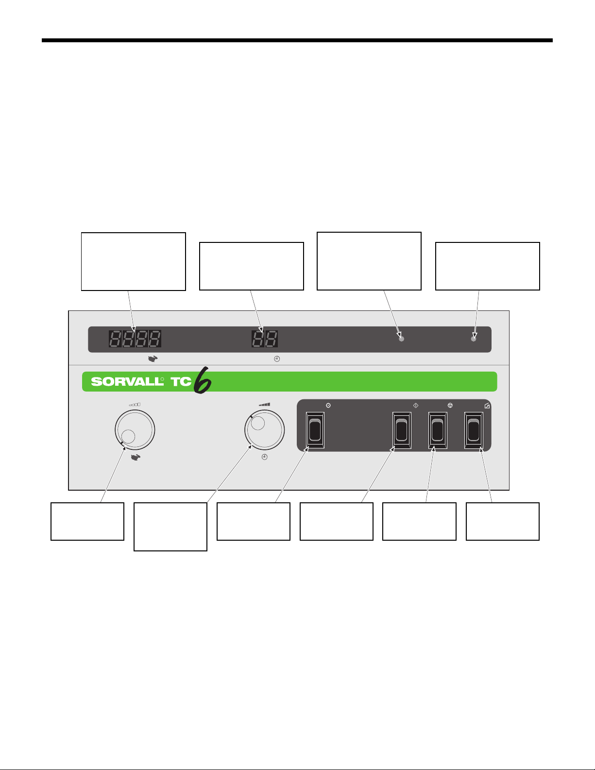
1-6. Controls, Displays,
Switches and Indicators
Figure 1-1 shows the TC6® control panel and provides a brief description for each control, display, switch and indicator. Table 1-1
(on the next page) gives a complete description.
SPEED DISPLAY
Displays actual rotor speed
from 0 to 6000 rpm (± 1%
or 10 rpm, whichever is
greater).
SPEED DIAL
Sets desired rotor
speed.
5
1
SPEED
RPM
R
TIME DIAL
Sets length of run
time up to 99 minutes.
TIME DISPLAY
Displays set run time and,
during a run, remaining run
time.
67
2
TIME
MIN
HOLD SWITCH
Selects a continuous run.
When lit, indicates that the
chamber door is closed and
latched and that the centrifuge is ready for operation.
START SWITCH
Starts the centrifuge run.
READY INDICATOR
3
READY DOOR
8
STOP SWITCH
Stops the centrifuge run.
DOOR INDICATOR
Blinks at end of run indicating the chamber door
may be opened.
9
4
DOORSTOPSTARTHOLD
DOOR SWITCH
10
Opens the chamber door.
Figure 1-1. TC6
®
Controls and Indicators
1-5
Page 14

Introduction and Description
SORVALL Centrifuges
Table 1-1. Description of Controls,
Displays, Switches and Indicators
SPEED display Indicates actual rotor speed from 0
to 6000 rpm (± 1% or 10␣rpm, whichever is greater).
TIME display Indicates set run time at the begin-
MIN
READY indicator light When lit, indicates that the chamber
DOOR indicator light At the end of the run this light blinks
ning of the run and the remaining
run time after the START switch is
pressed. In HOLD mode, two dashes
are displayed.
door is closed and latched and that
the centrifuge is ready for operation.
indicating that the rotor has stopped
spinning and that the chamber door
may be opened.
SPEED dial Sets the desired rotor speed in rpm.
As indicated by the symbol, turn the
dial to the right to increase speed.
TIME dial Sets length of run time up to 99 min-
utes.
HOLD switch Selects a continuous run (two dashes
will appear in the TIME display to
indicate a run in HOLD mode).
START switch Starts the centrifuge run.
STOP switch Stops the centrifuge run.
DOOR switch At the end of a run, after the rotor
has stopped spinning and the DOOR
light blinks, this switch releases the
chamber door.
POWER switch The power switch is a rocker switch
(NOT SHOWN)
that toggles on and off. When set to
"I", applies power to the centrifuge.
1-6
Page 15

Table of Contents
Contents
Section 2. Installation and Operation
2-1. Inspection . . . . . . . . . . . . . . . . . . . . . . . . . . . . . . . . . . . . . . . . . . . . . . . . . . . . . . 2-1
2-2. Preinstallation Requirements. . . . . . . . . . . . . . . . . . . . . . . . . . . . . . . . . . . . . . 2-1
2-3. Electrical Requirements . . . . . . . . . . . . . . . . . . . . . . . . . . . . . . . . . . . . . . . . . . 2-2
2-4. Voltage Selection . . . . . . . . . . . . . . . . . . . . . . . . . . . . . . . . . . . . . . . . . . . . . . . . 2-2
2-5. Installation . . . . . . . . . . . . . . . . . . . . . . . . . . . . . . . . . . . . . . . . . . . . . . . . . . . . . 2-4
2-6. Rotor Considerations . . . . . . . . . . . . . . . . . . . . . . . . . . . . . . . . . . . . . . . . . . . . 2-5
2-7. Running Hazardous Material . . . . . . . . . . . . . . . . . . . . . . . . . . . . . . . . . . . . . 2-6
2-8. Operation . . . . . . . . . . . . . . . . . . . . . . . . . . . . . . . . . . . . . . . . . . . . . . . . . . . . . . 2-7
2-9. Emergency Sample Recovery . . . . . . . . . . . . . . . . . . . . . . . . . . . . . . . . . . . . . 2-8
Installation Checklist
SORVALL Centrifuges
Page
viii
Page 16

®
TC6
Installation and Operation
Section 2: INSTALLATION and OPERATION
This section contains information to install and operate your SORVALL TC6® Tabletop Centrifuge.
2-1. Inspection
W A R N I N G
!
The TC6® weighs 70 lbs.
Refer to the unpacking instructions
for proper care when lifting and installing the centrifuge. Failure to use
proper lifting techniques can result in
personal injury and/or possible damage to the centrifuge.
C A U T I O N
!
Do not lift the centrifuge by
the front panel or the door. To do so
can result in damage to these parts.
C A U T I O N
!
The centrifuge can be damaged if connected to the wrong voltage. Check the voltage before plugging the centrifuge into any power
source. Sorvall is not responsible for
incorrect installation.
When you receive your centrifuge, carefully inspect it for any signs
of shipping damage. If you find damage, report it immediately to
the transportation company and file a damage claim, then notify
Sorvall.
Check the parts received with the centrifuge against the shipping
list; if any parts are missing, contact Sorvall (see office list in back of
manual).
2-2.␣ Preinstallation Require-
ments
The TC6® centrifuge is ordered for a specific voltage. The nameplate
on the back of the centrifuge tells the voltage ordered. Before using
the TC6®, be sure the proper operating voltage and corresponding
fuse is selected. If required (for instruments serial number 9501733
and below), the voltage setting and fuses can be changed (refer to
page 2-2, paragraph 2-4, Voltage Selection for procedure to change
the voltage).
Other preinstallation requirements include:
• providing a flat, level surface to support the weight of the
centrifuge (31 kg; 70 lbs),
• allowing adequate space for proper air circulation (5 cm;
2␣inches),
• allowing for the proper height clearance to open the chamber
door (78.7 cm; 31.0 inches); and
• providing the proper electrical requirements.
2-1
Page 17

Installation and Operation
SORVALL Centrifuges
C A U T I O N
!
If the power cord is
connected to the wrong voltage, it
can cause damage to the centrifuge.
Check the voltage listed on the
nameplate before plugging the power
cord into the power source. Sorvall is
not responsible for incorrect
installation.
2-3. Electrical Requirements
The centrifuge has specific power requirements and must be
connected to the correct power supply for proper performance. The
nameplate on the back of the centrifuge specifies one of the following:
100 - 120 Vac, 60 Hz, single phase, 3/15 amps*
220 - 240 Vac, 50 Hz, single phase, 2 amp*
Check line voltage with a voltmeter. Then, verify that the voltage
indicated on the nameplate on the back of the centrifuge agrees
with the measured line voltage.
If the line voltage is beyond the ±10% tolerance (of nominal) given,
the result can be variations in the performance specifications and
damage to the centrifuge.
The power cord has a keyed plug that inserts into a receptacle at the
back of the centrifuge. The other end of the power cord has a threeprong molded cap with a ground pin and parallel blades. (60 Hz
instruments require receptacle NEMA 5-15R and 50 Hz instruments
require NEMA 6-15 R.).
For connection to other receptacles, the power cord may have to be
replaced. Follow local electrical regulations.
Check that the gound lug of the electrical plug is properly grounded
and is shorted to the frame of the centrifuge.
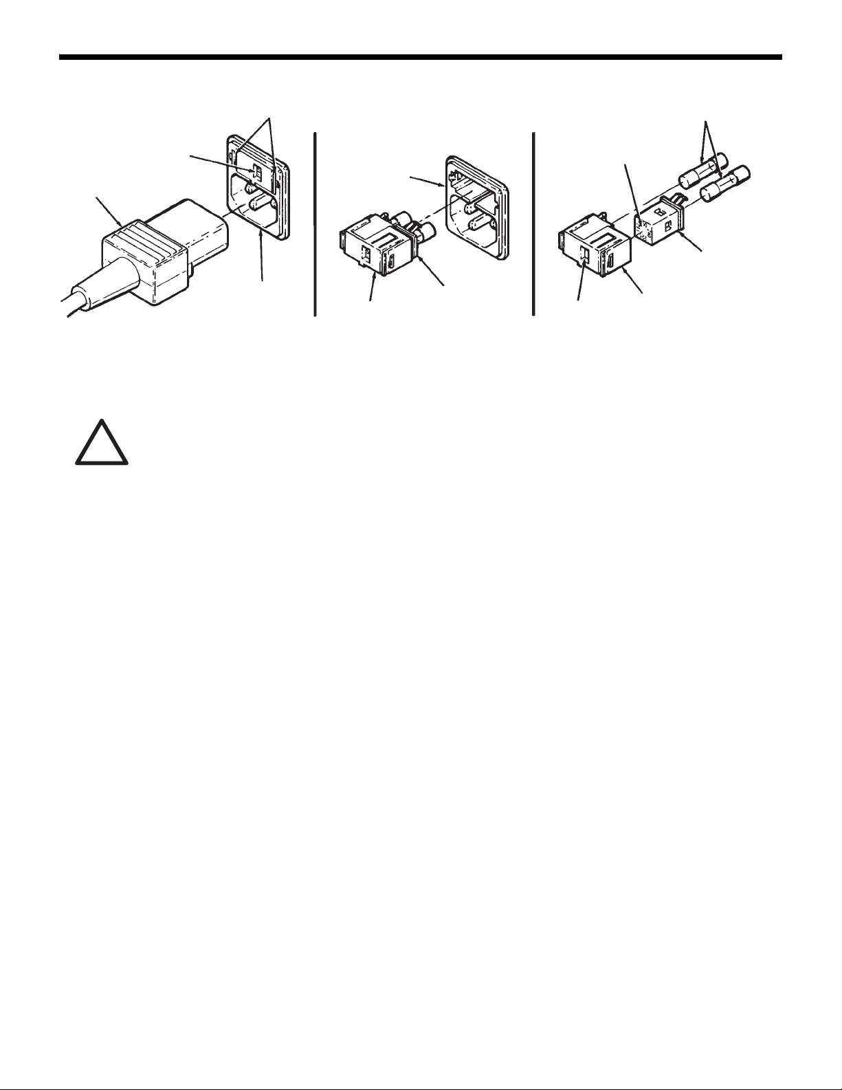
2-4. Voltage Selection
(SN 9501733 and Below)
The voltage is set by the voltage selector (in the fuse block) located
in the power connector on the back of the TC6® (refer to figure 2-1
for SN 9501733 and below). The current voltage setting (100, 110**,
220, or 240) is displayed in the window of the fuse block.
To change the voltage:
1. Unplug the power cord from the wall receptacle and from the
power connector.
2. Squeeze the two tabs located on either side of the fuse block and
carefully remove the fuse block from the power connector.
2-2
NOTE
*CSA and UL Certified.
**For 120 V operation, the voltage selector is set to 110.
Voltage can only be changed on instruments with serial
numbers 9501733 and below. Instruments with serial
numbers 9501734 and above must be ordered prewired
for specific voltages.
Page 18
TC6
®
Installation and Operation
SELECTED
VOLTAGE
POWER
CORD
WINDOW
POWER
CONNECTOR
Figure 2-1. Voltage Selection (SN 9501733 and below)
C A U T I O N
!
When changing the voltage
setting, be sure that the voltage
selector is installed so that the voltage
displayed in the voltage window
matches the intended input voltage.
Also, be sure that the proper fuses
have been installed, and that you are
using the proper power cord.
Incorrect installation can result in
damage to the centrifuge. Sorvall is
not responsible for incorrect
installation.
TABS
FUSES
SELECTABLE
POWER
CONNECTOR
FUSE
BLOCK
VOLTAGE
SELECTOR
VOLTAGE
WINDOW
VOLTAGES
VOLTAGE
SELECTOR
FUSE
BLOCK
3. Gently pull the voltage selector from the fuse block.
4. Rotate the voltage selector until the desired voltage is aligned
with the window in the fuse block. Then, reinstall the voltage
selector into the fuse block.
5. Check that proper fuses are installed. Fuses are Type T, 250 V,
but change amperage rating depending on the voltage selected:
• 100 or 110 setting requires two 3.15-amp fuses, (PN 91428),
• 220 or 240 setting requires two 2-amp fuses, (PN 91203).
Change fuses if necessary.
6. Reinstall the fuse block into the power connector and plug in
the centrifuge power cord.
NOTE
If the voltage was changed from 100-110 setting to 220240 setting, a different power cord is required.
2-3
Page 19

Installation and Operation
SORVALL Centrifuges
2-5. Installation
C A U T I O N
!
Do not lift the centrifuge by
the front panel or the chamber door.
To do so can result in damage to
these parts.
If the power cord is connected to the
wrong voltage, it can cause damage
to the centrifuge. Check the voltage
listed on the nameplate before
plugging the power cord into the
power source. Sorvall is not
responsible for incorrect installation.
Do not operate the centrifuge without
making sure the rotor is properly
balanced. Also, when installing a
rotor, carefully place it on the
centrifuge drive spindle. The
centrifuge spindle bearings can be
damaged if rotor is dropped on the
drive spindle.
To install the centrifuge:
1. Place the centrifuge on a sturdy bench or work table that will
support its weight, leaving space for sample preparation. Be
sure to leave a minimum clearance of 10 cm (4 inches) on all
sides for proper air circulation.
2. Make sure the centrifuge is level.
3. Make sure the centifuge is set for the proper voltage (see page
2-3, Voltage Selection).
4. Make sure the power switch is set to "O" (OFF position).
5. Insert the universal keyed end of the power cord into the power
connector at the back of the centrifuge and the other end into a
wall receptacle. The centrifuge is now ready for use.
2-6. Rotor Considerations
a. Rotor Temperature
W A R N I N G
!
Blocking the air flow entering and/or exiting the TC6® centrifuge will cause an increase in temperature within the rotor chamber. The
temperature increase can temporarily
distort non-metal surfaces allowing
particles to exit the rotor chamber
resulting in personal injury and/or centrifuge damage should tube breakage or rotor failure occur.
When loading the rotor, be sure not
to exceed the maximum compartment
mass of the rotor (see the individual
rotor instruction manual). If maximum
compartment mass is exceeded,
maximum rotor speed must be
lowered as described in the rotor
instruction manual, Compartment
Loads in Excess of Design Mass.
Failure to do so can cause rotor failure
which could result in personal injury
and/or centrifuge damage.
Centrifugation creates an increase in rotor temperature. The increase
in temperature is caused by variables including rotor speed, length
of the run, and the type of rotor.
Air flow through the TC6® Centrifuge is designed to minimize the
increase in rotor temperature. Air enters through the air vent in the
front panel and exits through the fan vent located at the back of the
centrifuge.
When running temperature-sensitive material, a trial run is
recommended.
b. Rotor Installation, Loading and Balancing
Before placing the rotor on the drive spindle, make sure that there
are no loose objects inside the rotor chamber; for example, clips,
tubing, tape, or labels, and that the rotor centerhole and drive
spindle are clean and free of nicks and scratches. Wipe these surfaces
before each use.
Gently place the rotor body on the tapered spindle of the centrifuge,
aligning the shaft pin with the slots in the rotor. Secure the rotor to
the drive spindle by turning the rotor locking knob clockwise.
2-4
Page 20

TC6
®
Installation and Operation
C A U T I O N
!
Do not operate the centrifuge without making sure the rotor is
properly balanced. Also, when installing a rotor,
centrifuge drive spindle. The centrifuge drive spindle bearings can be
damaged if the rotor is dropped on
the drive spindle.
carefully
place it on the
W A R N I N G
!
When using radioactive,
toxic, or pathogenic materials, be
aware of all characteristics of the
materials and the hazards associated
with them in the event leakage occurs during centrifugation. If leakage
does occur, neither the centrifuge nor
the rotor can protect you from particles dispersed in the air. To protect
yourself, we recommend additional
precautions be taken to prevent exposure to these materials, for example, use of controlled ventilation
or isolation areas.
Always be aware of the possibility of
contamination when using radioactive, toxic, or pathogenic materials.
Take all necessary precautions and
use appropriate decontamination procedures if exposure occurs.
NOTE
The rotor locking knob cannot be tightened if the rotor is
not properly installed on the drive spindle.
Refer to the rotor instruction manual for bucket loading and balancing procedures as well as information regarding the selection and
use of tubes, bottles, and adapters.
2-7. Running Hazardous
Material
Because the centrifuge chamber of the TC6® is not designed for
biocontainment, some vapors or aerosols released from uncapped,
leaking or broken tubes may leak from the chamber during operation.
Once a run is completed and the chamber door is opened, the
vapors or aerosols which have concentrated in the chamber will be
released into the laboratory area. For this reason, when materials
which are radioactive, pathogenic, toxic, or otherwise hazardous in
nature are to be run, the centrifuge should be located in a biohazard
safety enclosure and operated using all appropriate safety
precautions. If desired, we recommend the use of sealed bucket
assembly (Catalog No. 78016) to offer increased protection from
contamination from uncapped, leaking or broken tubes.
NOTE
The sealed bucket assemblies (Catalog No. 78016) are
designed to seal tightly during operation and meet the
British Standards BS 4402:1982 Appendix D. They have
been tested at the Public Health Laboratory Service
Centre for Applied Microbiology and Research, Porton
Down, United Kingdom, and found suitable for use with
materials up to ACDP Category 3.
The use of sealed rotors, buckets and/
or sample containers will provide increased protection from contamination during routine operation. However, these items will not guarantee
contamination protection from accidents resulting in damage to the rotor
or buckets. Do not run hazardous material in the centrifuge unless it is
placed in a biohazard enclosure and
operated using appropriate safety precautions.
Use appropriate decontamination procedures should exposure to
any hazardous material occur. Read paragraph 1-2, page 1-1 for the
procedure to follow if a centrifuge or rotor that has been used with
a hazardous material must be returned to our service facilities for
repair.
2-5
Page 21

Installation and Operation
SORVALL Centrifuges
2-8. Operation
W A R N I N G
!
Be sure the rotor chamber
and chamber door gasket are installed
before the centrifuge run. Operating
the centrifuge without these parts in
place could allow small particles to
exit the rotor chamber in the event of
a rotor failure.
C A U T I O N
!
Be sure the rotor is properly balanced and seated on the drive
spindle. All four buckets must be
used on every run (even if empty).
See rotor instruction manual.
To perform the run:
1. Set the POWER switch to "I".
2. Press the DOOR switch to release the chamber door.
3. Install the rotor on the drive spindle and close the chamber
door. When properly closed, the lid latch automatically locks
the door and the READY indicator light comes on.
4. Set the SPEED dial to the desired run speed.
NOTE
5. Turn the TIME dial to the desired run time (the run time, in
Selected run speed is to be verified and adjusted during
the run after the value shown in the SPEED display has
stabilized. Adjust the SPEED dial until the SPEED
display indicates desired run speed (in rpm). If it is not
disturbed, the SPEED dial will retain its position, allowing
for run-to-run repeatability.
minutes, will appear in the TIME display); or press the HOLD
switch to ON for a continuous run and two dashes (--) will
appear in the TIME display.
6. Press START switch to begin run.
NOTE
7. At the end of the run, the DOOR indicator light blinks indicating
NOTE
If the door is not properly closed, the READY indicator
light will not come on and the rotor will not spin when the
START switch is pressed.
To end a run before the selected run time has elapsed or
to end a run set to HOLD, press the STOP switch.
that the chamber door can be opened. Press the DOOR switch to
open the chamber door.
Remove the sample from the rotor, close the chamber door, and
set the POWER switch to "O".
The speed and time values selected at the beginning of
the run are automatically retained unless the power cord
is disconnected from the power source. To do another
run with the same run speed and time parameters:
prepare the rotor, install it in the centrifuge, close the
chamber door, and press the START switch.
2-6
Page 22
TC6
®
Installation and Operation
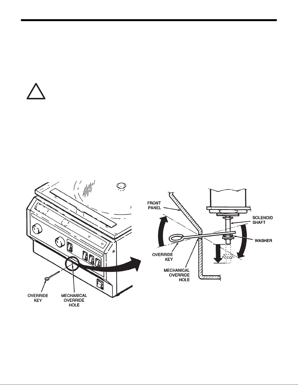
2-9. Emergency Sample
Recovery
If the main power shuts off because of a power failure or system
malfunction, the chamber door will not open. A mechanical override is provided to allow sample recovery in the case of an emergency.
W A R N I N G
!
This procedure is included
for
emergency sample recovery only
and should never be used for any
purpose other than those explained
in this section.
When the main power shuts off, the
brake will not operate. Unplug the
centrifuge plower cord and wait until
the motor stops spinning
ing the mechanical override.
before
us-
The mechanical override is located below the air inlet vent in the
front panel, as shown in figure 2-3. To operate the override, insert
the end of the override key (PN 78170 supplied), at a slight upward
angle 2/3 of the way into the hole. Carefully move the key left-toright until you locate the solenoid shaft. Slowly move the end of the
key downward to contact the washer located at the bottom of the
shaft. With the key pressed tight against the solenoid shaft, use the
key as a lever to apply downward pressure on the washer to release
the chamber door.
Figure 2-2. Location of the Mechanical Override
2-7/2-8
2-7
Page 23

®
SORVALL Centrifuges
INSTALLATION CHECKLIST
TC6® TABLETOP
CENTRIFUGE
Institution _________________________________
Street Address _____________________________
___________________________________________
City _______________________________________
State/Province _____________________________
Postal Code ________________________________
Country ___________________________________
Phone No. _________________________________
Inspection (paragraph 2-1)
Shipping damage
Accessories included
Preinstallation (paragraph 2-2)
Confirm voltage on instrument
Electrical Requirements
(paragraph 2-3)
Line voltage
Ground Continuity
Date _________________________________
Serial Number _______________________
Packing List No.______________________
User _________________________________
Installed by __________________________
Voltage Selection (paragraph 2-4)
Check fuse block/correct fuses
Installation (paragraph 2-5)
Sturdy bench
Level surface
Operation (paragraph 2-8)
Perform run
Acceleration time
Deceleration time
Door Latch
Comments: ______________________________________________________________________________
__________________________________________________________________________________________
__________________________________________________________________________________________
__________________________________________________________________________________________
__________________________________________________________________________________________
__________________________________________________________________________________________
__________________________________________________________________________________________
__________________________________________________________________________________________
__________________________________________________________________________________________
__________________________________________________________________________________________
__________________________________________________________________________________________
__________________________________________________________________________________________
__________________________________________________________________________________________
Signature of Installer ____________________________________________________________________
Date
Page 24

®
TC6
Contents
Section 3. System Descriptions
3-1. General System Description. . . . . . . . . . . . . . . . . . . . . . . . . . . . . . . . . . . . . . . 3-1
3-2. Power System. . . . . . . . . . . . . . . . . . . . . . . . . . . . . . . . . . . . . . . . . . . . . . . . . . . 3-2
3-3. Drive Motor . . . . . . . . . . . . . . . . . . . . . . . . . . . . . . . . . . . . . . . . . . . . . . . . . . . . 3-2
3-4. Brushless Motor Drive Electronics . . . . . . . . . . . . . . . . . . . . . . . . . . . . . . . . . 3-2
3-5. Speed Control. . . . . . . . . . . . . . . . . . . . . . . . . . . . . . . . . . . . . . . . . . . . . . . . . . . 3-6
3-6. Timer . . . . . . . . . . . . . . . . . . . . . . . . . . . . . . . . . . . . . . . . . . . . . . . . . . . . . . . . . . 3-7
3-7. Door Latching Mechanism. . . . . . . . . . . . . . . . . . . . . . . . . . . . . . . . . . . . . . . . 3-7
Table of Contents
Page
ix
Page 25

®
TC6
Section 3: SYSTEM DESCRIPTIONS
3-1. General System Description
The TC6® is an assembly that consists of the following:
• Power System
• Drive Motor System
• Control System
• Input/Output System
• Cabinet System
• Ventilation System
• Containment System
The Power System consists of the cord, voltage selector (SN 9501733
and below), power supply, and electrical connectors. It takes electricity from the electric outlet, converts it to low voltage and then
distributes it to the other instrument systems.
System Descriptions
The Drive Motor System consists of the motor, drive electronics and
drive mount hardware. It receives controlled voltage from the control
system to spin the rotor while providing support for itself and the
rotor system.
The Control System consists of electrical circuits that are located on
printed circuit boards to control operation of the motor speed, the
timer and the latch mechanism.
The Input/Output System is a user interface system that consists of
knobs, switches, and displays. It allows the user to input run
parameters and also monitors a run in progress.
The Cabinet System consists of the upper and lower frame sections.
This system forms the main body of the centrifuge and supports the
other instrument systems.
The Ventilation System consists of a fan, gaskets and baffles. It
directs air movement in the centrifuge to cool the circuits and motor
and also seals the rotor chamber to minimize windage.
The Containment System consists of radial and vertical containment
sub-systems. The radial sub-system is the guard and containment
rings and their supports. The vertical containment sub-system is
the door, latch and striker, and the mounting hardware. The
containment system is designed to contain any parts or fragments
that may result from a rotor failure.
3-1
Page 26

System Descriptions
SORVALL Centrifuges
3-2. Power System
Theory of Operation
The electrical power portion of this centrifuge starts in the line cord
entry module. This module accepts a standard three wire power
cord. Both sides of the line are fused. The 100 - 120 volt centrifuges
are fused at 3.15 amps and the 220 - 240 volt centrifuges at 2 amp.
(SN 9501733 and below), 120 V (±10%) and 230 V (±10%) (SN
9501734 and above). This centrifuge is designed to work on either
50 or 60 hertz at any of the input voltages. No changes are necessary
to accommodate different line frequencies.
The other portion of the power system is the dc power supply. This
is a dual supply generating nominally 30␣volts at 10␣amps and
5␣volts at 500␣milliamps. Ther e is a fast acting fuse of 6.3␣amps on
the 30␣volt secondary of the transformer and a fast-acting fuse of 1.6
amps on the 5␣volt secondary of the transformer . The bridge rectifiers and 5 volt regulator are heatsinked to the chassis. The 30␣volt
supply is used by the motor control circuitry, the motor, and the
latch release solenoid. The 5␣volt supply is for powering the displays, speed and timer logic; and the operator I/O logic.
3-3. Drive Motor
Theory of Operation
The motor is a brushless dc type. Four Ferrite magnets are adhesive
bonded to the steel shaft to make up the rotor. Arranged around the
rotor in the case are three excitation coils. To sense motor position,
three␣Hall-ef fect devices are mounted at the bottom of the case.
3-4. Brushless Motor Drive
Electronics
The TC6® drive is a type of power inverter motor drive. The functional purpose is to convert raw single phase ac power into synchronous three-phase power to the motor. This is accomplished in
several stages. The following is a brief description of how the
internal power conversion process occurs.
Power Conversion from ac to dc – The ac power source may be
selected for a nominal voltage of 100 - 120 or 220 - 240 volts ac-RMS
at a frequency of between 48 to 62 Hz. Only single phase ac is used.
Raw ac, used for the motor power, passes into a full wave bridge
3-2
Page 27

TC6
®
System Descriptions
rectifier and then into filter capacitors. The combination of these
components provides a nominal 30 volt unregulated dc power
source.
Power Inversion from dc to ac – The unregulated dc power available
in the TC6® must be converted back to phased ac power for the
motor to operate. This process is called inversion. For proper control
of motor rotation, the drive must synchronize the application of
power precisely with the rotational position of the rotor. This process
is commonly referred to as commutation. The motor used in the
centrifuge requires three-phase ac power for commutation.
The three-phase ac power used to "commutate" the motor is phase
displaced in time by 120 electrical degrees. The ac power delivered
is pulsed square waves and provides variable frequency ac to the
motor. This feature enables the motor to operate at variable speeds.
The three-phase ac power delivered to the motor is developed by an
active circuit network consisting of six power transistors. This network is called the output bridge. In order to sustain the rotation of
the centrifuge the drive continuously processes and decodes rotor
position information. This information is used to sequentially apply
power from the output bridge to the motor.
It is not sufficient to precisely control the motor through commutation
alone. The power applied to the motor must be carefully metered in
order to throttle both torque and speed. This is accomplished through
a technique called pulse width modulation, or PWM.
The PWM technique provides a method of efficient power control
through the use of high frequency output bridge modulation. In
effect, as each motor winding is turned on in sequence during
motor rotation, PWM is superimposed upon the normal
commutation signals. PWM results in the application of power to
the motor by chopping it on and off at a high rate (24 kHz). This
chopping scheme controls average motor current by varying the
ratio of "on time" versus "off time" for each PWM cycle. This chopping
scheme provides proportional output torque from the motor through
the direct adjustment of the average motor current.
The drive limits torque by continuously monitoring the electrical
current to the motor and comparing it to the commanded level
requested by the control setting. The difference between these two
levels results in an error signal which is then converted to a PWM
ratio. This PWM is used to modulate the output bridge as described
above.
3-3
Page 28

System Descriptions
SORVALL Centrifuges
a. Theory of Operation
The drive is built with Motorola's MC33035 and a support chip
MC33039.
The MC33035 is a 24-pin linear integrated circuit (I.C.) that operates
as the control center for the brushless dc motor control system. The
main functions of MC33035 are to decode the signals from the
Hall-effect sensors and generate logic for electronically commutating
the motor. The commutation logic is internally delivered to the six
output drivers consisting of three open collector NPN transistors
that drive the upper legs of the bridge and three totem pole drivers
that control the devices. The open collector outputs can sink 50 mA.
With some additional circuitry this allows control of either N-channel
MOSFETs for higher power applications or P-channel MOSFETs if a
simple interface is desired. Since the three lower totem pole outputs
can source and sink 10 mA, they can drive power MOSFETs directly.
b. Fault Management
The MC33035 can detect and manage several types of faults. A
common method of overcurrent detection is to tie the sources of the
lower three transistors together and return them to the negative
supply rail through a current sense resistor. The sense voltage,
which is proportional to load current, is delivered into a comparator
on board the MC33035. The comparator then delivers an RS flip-flop,
which ensures that the output drivers will turn off the power
transistors for the remainder of the oscillator cycle if an overcurrent
condition is detected. Without the internal flip-flop, the overcurrent
protection loop would rapidly cycle on and off about the
comparator's threshold, causing excessive power transistor heating.
In addition to overcurrent management, the MC33035 provides
undervoltage lockouts that terminate the drive to the output transistors if any of three conditions occur:
• insufficient voltage to operate the I.C.;
• insufficient voltage to drive the power MOSFET gates; or
• output drivers turn the power transistors off when the MC33035
does not sustain its on-board 6.25 V reference.
An invalid set of Hall-effect signals or excessive temperature will
also cause shutdown.
3-4
Whenever any fault condition exists, an NPN transistor capable of
sinking 16 mA pulls the Fault Output pin low.
Page 29

TC6
®
System Descriptions
c. Control Features
The MC33035's circuitry contains all except one major element for
closed-loop speed control. The missing element is that which
monitors motor rpm (speed) and generates a signal proportional to
motor speed, a function that has been the domain of a tachometer
Once provided with a motor speed signal, the MC33035's high
performance error amplifier and its internal oscillator form the last
major links in the speed control loop.
The MC33035's on-board oscillator operates at a frequency set by an
external resistance/capacitance (R-C). Each cycle capacitor is charged
from the reference output through a resistor and then rapidly
discharged through an internal transistor.
At each positive or negative transition of the Hall-effect sensors,
the MC33039 generates a pulse with a fixed on time. The output
signal can then be filtered to obtain a voltage proportional to motor
speed. Design of an MC33035/39 based system should begin with
setting the system timing, which originates in the MC33039. Selection
of timing components for MC33039 is based on the desired maximum
motor rpm. For the motor used in this application, there are two
electrical degrees for every mechanical degree since the permanent
magnet on the rotor has two pairs of poles. Therefore, for every
mechanical revolution each Hall-effect sensor delivers two pulses
and the three sensors generate six pulses. The MC33039 generates
12 pulses for each revolution, one for each rising and falling edge.
For a given maximum rotor speed, the output pulse width has a
maximum limit. For example, the maximum speed is 6000␣rpm,
which is 100␣r evolutions per second, the MC33039 will generate
100␣x␣12, or 1200␣pulses per second. The >1kHz␣fr equency determines that the maximum pulse width must be less than 1␣ms. One
can determine that R1 and C1 values of 30␣k and 22␣nF r esults in a
pulse width of 600␣ µs. To set the system PWM frequency, refer to the
MC33035's data sheet. There it shows that setting R2 and Cw to
5.1␣k and 0.01␣ µ F gives a nominal PWM frequency of 24␣kHz, just
above the audible range.
Both inputs and the outputs of the MC33035's error amplifier are
accessible to accommodate various control methods. For open-loop
control a reference signal proportional to the desired speed can be
fed into the error amplifier's non-inverting input. The error amplifier output is then configured as a unity gain voltage follower by
connecting its inverting input to its output. The error amplifier's
output is then compared to the output of the oscillator to obtain a
PWM signal proportional to the desired motor speed--unless the
control loop is overridden by an overcurrent or fault condition.
3-5
Page 30

System Descriptions
SORVALL Centrifuges
For closed-loop control, one approach is to filter the MC33039's
output with a low pass filter to generate a voltage proportional to
motor speed and feed the resulting signal into the inverting input of
the MC33035's comparator. A signal proportional to desired motor
speed drives the non-inverting input, and the ratio of the input and
feedback resistors R3 and R4 control gain. In this design, low pass
filtering and generating the error signal are combined by using
feedback capacitor, C3.
Ideally, the integrator/error amplifier should produce a ripple free
output even at low motor speeds. To do so at very low speeds
reduces system response time, however. Component values must
be adjusted according to the rotors' load, inertia and friction. In this
particular application the values 2 M ohm and 0.01 µF give good
dynamic response and stability.
When motor speed is less than the desired speed, the MC33035
extends the output pulse width to the drive transistors. When
motor speed is greater than the desired speed, the duty cycle decreases. However, if the input signal abruptly demands a much
lower speed, the duty cycle could fall to zero and the motor would
coast to desired low speed. Therefore, since the MC33035 has no
provision to dynamically brake the motor and thus control rapid
deceleration, it is best suited for applications which have a large
frictional load or those that do not require a controlled, abrupt
deceleration.
d. Braking
Dynamic braking is used. The three high-side motor drive transistors are turned off and the three low-side drive transistors are
turned on, in sequence. This circulates the back Electro Magnetic
Force (EMF) generated currents through the motor winding for
dissipation of stored energy.
A logic high at pin 2 of the motor drive control connector calls for
dynamic braking.
3-5. Speed Control
Theory of Operation
Speed control is accomplished by a 10k ohm potentiometer used in
conjunction with the Motorola brushless motor control chip
integrated circuit set (MC33035 and MC33039). The wiper of the
potentiometer is the control input to MC33035. Lower speed is
selected when the voltage on the wiper is decreased (by turning
counterclockwise) and higher speed is selected when voltage on the
wiper is increased (by turning clockwise).
3-6
Page 31

TC6
®
The motor has three Hall-effect sensors internally mounted to
generate pulses as the motor turns. These pulses are monitored by
the MC33035 allowing the controller to change the width of the
pulse sent to the motor drive to control the speed. The wider the
pulse, the faster the motor runs.
The sensors are also used to generate a pulse string for the speed
indicator. MC33039 generates 12 pulses for each revolution of the
motor.
System Descriptions
3-6. Timer
Theory of Operation
The timer consists of a crystal controlled oscillator and a variety of
"HC" (High speed Complementary metal oxide semiconductor)
logic circuitry operating on 5 Vdc. When the timer elapses to zero,
the rotor motor begins to brake.
If HOLD mode is selected, the timer is disabled and the centrifuge
continues to run until the operator presses the ST OP switch to end
the run.
3-7. Door Latching Mechanism
Theory of Operation
The door closing/locking mechanism is a latch, secured to the
underside of the frame; a striker, secured to and extending through
the chamber door; a latch release activated by a solenoid; a door
closure sensor; and a door release button. Door open/close position
is monitored by a magnetic switch.
The circuitry that controls the door latch solenoid is on the Control
Printed Circuit Board. When the door open switch is closed, the
solenoid is energized for less than one second no matter how long
the switch is held. It consists of logic gate controls and solenoid
driver circuits. The logic controlling the door release solenoid must
meet all of the following conditions before the door open switch
will operate:
• door closed
• timer not active
• low speed (less than 90 rpm).
The Latch solenoid cannot be energized when rotor speed is more
than 62 rpm.
3-7/3-8
3-7
Page 32

Table of Contents
SORVALL Centrifuges
Contents
Section 4. Printed Circuit Boards and Schematics
Figures
Page
4-1. System Wiring Diagram, Rev. 3 . . . . . . . . . . . . . . . . . . . . . . . . . . . . . . . . . . . . 4-3
4-2. System Wiring Diagram, Rev. 2 . . . . . . . . . . . . . . . . . . . . . . . . . . . . . . . . . . . . 4-5
4-3. Schematic for Control Printed Circuit Board, PN 78189 Rev. 3 . . . . . . . . . 4-7
4-4. Control Printed Circuit Board Assembly, PN 78189 Rev. 3 . . . . . . . . . . . . . 4-9
4-5. Schematic for Display Printed Circuit Board, PN 78178 Rev. 4 . . . . . . . . . 4-13
4-6. Display Circuit Board Assembly, PN 78178 Rev. 4 . . . . . . . . . . . . . . . . . . . . 4-15
4-7. Schematic for Display Printed Circuit Board, PN 78178 Rev. 2 . . . . . . . . . 4-19
4-8. Display Printed Circuit Board Assembly, PN 78178 Rev. 2 . . . . . . . . . . . . . 4-21
4-9. Schematic for Power Supply Printed Circuit Board, PN 78049 Rev. 4 . . . . 4-24
4-10. Power Supply Printed Circuit Board Assembly, PN 78049 Rev. 4 . . . . . . . 4-25
4-11. Schematic for Power Supply Printed Circuit Board, PN 78049 Rev. 2 . . . . 4-27
4-12. Power Supply Printed Circuit Board Assembly, PN 78049 Rev. 2 . . . . . . . 4-28
4-13. Schematic for Power Supply Printed Circuit Board, PN 78049 Rev. 1 . . . . 4-30
4-14. Power Supply Printed Circuit Board Assembly, PN 78049 Rev. 1 . . . . . . . 4-31
4-15. Schematic for Motor Control Printed Circuit Board, PN 78230 Rev. 4 . . . 4-33
4-16. Motor Control Printed Circuit Board Assembly, PN 78230 Rev. 4 . . . . . . . 4-35
4-17. Schematic for Motor Control Printed Circuit Board, PN 78230 Rev. 4 . . . 4-39
4-18. Motor Control Printed Circuit Board Assembly, PN 78230 Rev. 4 . . . . . . . 4-41
4-19. Schematic for Motor Control Printed Circuit Board, PN 78230 Rev. 0 . . . 4-45
4-20. Motor Control Printed Circuit Board Assembly, PN 78230 Rev. 0 . . . . . . . 4-47
Tables
x
4-1. Component Description, Control Printed
Circuit Board, PN 78189 Rev. 3 . . . . . . . . . . . . . . . . . . . . . . . . . . . . . . . . . . . 4-11
4-2. Component Description, Display Printed
Circuit Board, PN 78178 Rev. 4 . . . . . . . . . . . . . . . . . . . . . . . . . . . . . . . . . . . 4-17
4-3. Component Description, Display Printed
Circuit Board, PN 78178 Rev. 2 . . . . . . . . . . . . . . . . . . . . . . . . . . . . . . . . . . . 4-23
4-4. Component Description, Power Supply Printed
Circuit Board, PN 78049 Rev. 4 . . . . . . . . . . . . . . . . . . . . . . . . . . . . . . . . . . . 4-26
4-5. Component Description, Power Supply Printed
Circuit Board, PN 78049 Rev. 2 . . . . . . . . . . . . . . . . . . . . . . . . . . . . . . . . . . . 4-29
4-6. Component Description, Power Supply Printed
Circuit Board, PN 78049 Rev. 1 . . . . . . . . . . . . . . . . . . . . . . . . . . . . . . . . . . . 4-32
4-7. Component Description, Motor Control Printed
Circuit Board, PN 78230 Rev. 4 . . . . . . . . . . . . . . . . . . . . . . . . . . . . . . . . . . . 4-36
4-8. Component Description, Motor Control Printed
Circuit Board, PN 78230 Rev. 4 . . . . . . . . . . . . . . . . . . . . . . . . . . . . . . . . . . . 4-42
4-9. Component Description, Motor Control Printed
Circuit Board, PN 78230 Rev. 0 . . . . . . . . . . . . . . . . . . . . . . . . . . . . . . . . . . . 4-48
Page
Page 33

®
TC6
Printed Circuit Boards & Schematic Diagrams
Section 4: PRINTED CIRCUIT BOARDS and
SCHEMATIC DIAGRAMS
This section contains a system wiring diagram as well as schematic diagrams and component description
tables for printed circuit boards found in the TC6® Tabletop Centrifuge.
4-1/4-2
4-1
Page 34

TC6
®
Printed Circuit Boards & Schematic Diagrams
Figure 4-1. System Wiring Diagram,
(SN 9501734 and above)
(SN 9600946 and above, 60 Hz only, Do Not Use Line Filter)
4-3/4-4
Page 35

TC6
®
Printed Circuit Boards & Schematic Diagrams
Figure 4-2. System Wiring Diagram,
(SN 9501733 and below)
4-5/4-6
Page 36

TC6
®
Printed Circuit Boards & Schematic Diagrams
Figure 4-3. Schematic for Control Printed
Circuit Board, PN 78189 Revision 3
4-7/4-8
Page 37

TC6
®
Printed Circuit Boards & Schematic Diagrams
Figure 4-4. Control Printed Circuit Board
Assembly, PN 78189 Revision 3
4-9/4-10
Page 38

TC6
®
Printed Circuit Boards & Schematic Diagrams
Table 4-1. Component Description,
Control Printed Circuit Board, PN 78189 Revison 3
(refer to figure 4-4)
Component Description
R5 Resistor, 1.0 KΩ, 1/4W, 5%, Carbon Comp.
R15, R16, R18, Resistor, 10 KΩ, 1/4W, 5%, Carbon Comp.
R20, R23, R24, R25
R6 Resistor, 1.0 MΩ, 1/4W, 5%, Carbon Comp.
R8, R9 Resistor, 1.5 KΩ, 1/4W, 5%, Carbon Comp.
R10 Resistor, 2 KΩ, 5W, 5%, Wirewound
R11, R12, R13, Resistor, 22 KΩ, 1/4W, 5%, Carbon Comp.
R14, R17
R22 Resistor, 3.3 KΩ, 1W, 5%, Carbon Comp.
R19, R21 Resistor, 4.7 KΩ, 1/4W, 5%, Carbon Comp.
R4, R7 Resistor, 47 KΩ, 1/4W, 5%, Carbon Comp.
R1 Resistor, 75Ω, 15W, 5%, Carbon Comp.
C5, C7, C9, C13, Capacitor, 0.01 µF, 50V
C14, C15, C16, C18,
C19, C20, C21, C22,
C23, C24, C25, C26,
C27, C28, C29, C30,
C32, C33, C34, C35
C6, C8 Capacitor, 0.1 µF, 50V, 20%
C4, C11, C36 Capacitor, 2.2 µF, 50V, 20%
C2, C10, C12 Capacitor, 47 µF, 16V, 20%
U13, U14, U15 I.C., CMOS, Dual BCD, MC14518BP
U18, U21 I.C., CMOS, Phase Comp/Prog Cntrs, MC14568BP
U10, U11 I.C., CMOS, Dual J-K Flip Flop, MC74HC76N
U3, U8, U19 I.C., CMOS, Schmitt Trigger, MC14106BP
U20 I.C., CMOS, Time Base Gen., MC14566BP
U2 I.C., CMOS, Bounce Elim., MC14490P
4-11
Page 39

Printed Circuit Boards & Schematic Diagrams
Table 4-1. Component Description,
Control Printed Circuit Board, PN 78189 Revision 3 (continued)
(refer to figure 4-4)
Component Description
U9 I.C., CMOS, Quad AND, MC74HC08N
U5 I.C., CMOS, 3 Input NAND, MC74HC10N
U4, U6, U22 I.C., CMOS, Quad NAND, MC74HC00N
U1 I.C., Hi-Volt Source Driver, UND-2983A
U7 I.C., CMOS, Dual Multivibrator, MC74HC4538N
U16 I.C., CMOS, Opto-Isolator, H11A1
SORVALL Centrifuges
U17 I.C., CMOS, Hex Inverter, CD4069UBE
Q1 Transistor, Power N-Channel E-FET
Q2 I.C. Undervolt Sensing, MC34064P-5
Q3 Transistor, NPN Type, 2N2222
Y1 Resonator, Ceramic, 2MHz
K1 Relay, PCB Type, SPDT
CR1, CR2, CR3, CR4 Diode, Zener, IN6270A, 9.1V
CR5. CR6 Diode, Silicon, 100V/1A, IN4002/IN4002GP
CR7 Diode, Surge Type, 600W
J30 Connector, Header, 26 Position
J31 Connector, Header, 20 Position
J33 Connector, Header, 16 Position
4-12
J32 Connector, Header, 10 Position
TP2 Connector, Header, 3 Pin
J1 Plug, Interconnection, 2 Position
TP1 Test Points
Page 40

TC6
®
Printed Circuit Boards & Schematic Diagrams
Figure 4-5. Schematic for Display Printed
Circuit Board, PN 78178 Revision 4
4-13/4-14
Page 41

TC6
®
Printed Circuit Boards & Schematic Diagrams
Figure 4-6. Display Printed Circuit Board
Assembly, PN 78178 Revision 4
4-15/4-16
Page 42

TC6
®
Printed Circuit Boards & Schematic Diagrams
Table 4-2. Component Description,
Display Printed Control Board, PN 78178 Revision 4
(refer to figure 4-6)
Component Description
R1, R2 Resistor, 4.7 KΩ, 1/4W, 5%, Carbon Comp.
R3, R4, R5 Resistor, 82Ω, 1/4W, 5%, Carbon Comp.
C1, C2, C3,C4, Capacitor 0.01 µF, 50V
C5, C6, C7, C8,
C9, C10, C11,
C13, C14, C15
C12 Capacitor 47 µF, 6 V
DS1, DS2 LED, Green, Diffused
CR1, CR2, Diode, SI., IN914 or IN4148
CR3, CR4
U5 I.C., CMOS, Octal Bus Transceiver, 74HC245AN
U10, U13 I.C., CMOS, BCD Decoder/Driver, Harris CA3161E
U7 I.C., CMOS, Dual Multivibrator, 74HC4538N
U6 I.C., CMOS, Quad NAND, 74HC132AN
U9 I.C., CMOS, Quad or, 2-Input, 74HC32AN
U1, U2, I.C., CMOS, BCD Counter, MC14510BP
U3, U4
U8 I.C., CMOS, Schmitt Trigger, MC14106BCP
U11, U12, U15, I.C., Display, 7 Segment, HP5082-7651
U16, U17, U18
U14 I.C., Display, 4 1/2 Digit, Harris ICM7225IPL
C16 Capacitor, 22 µF, 50V
4-17/4-18
4-17
Page 43

TC6
®
Printed Circuit Boards & Schematic Diagrams
Figure 4-7. Schematic for Display Printed
Circuit Board, PN 78178 Revision 2
4-19/4-20
Page 44

TC6
®
Printed Circuit Boards & Schematic Diagrams
Figure 4-8. Display Printed Circuit Board
Assembly, PN 78178 Revision 2
4-21/4-22
Page 45

TC6
®
Printed Circuit Boards & Schematic Diagrams
Table 4-3. Component Description,
Display Printed Circuit Board, PN 78178 Revision 2
(refer to figure 4-8)
Component Description
C1, C2, C3, C4, Capacitor, 0.01 µF, 50V
C5, C6, C7, C8,
C9, C10, C11,
C13, C14, C15
C12 Capacitor, 47 µF, 6V
CR1, CR2, Diode, IN914 or IN4148
CR3, CR4
DS1, DS2 LED, Green, Diffused
R1, R2 Resistor, 4.7 KΩ, 1/4W, 5%, Carbon Comp.
R3, R4, R5 Resistor, 82 Ω, 1/4W, 5%, Carbon Comp.
U1, U2, I.C. CMOS, BCD Counter, MC14510BP
U3, U4
U5 I.C., CMOS, Octal Bustransceiver, 74HC245AN
U6 I.C., CMOS, Quad NAND, 74HC132AN
U7 I.C., CMOS, Dual Multivibrator, 74HC4538N
U8 I.C., CMOS, Schmitt Trigger, MC14106BCP
U9 I.C., CMOS, Quad or, 2-Input, 74HC32AN
U10, U13 I.C., CMOS, BCD Decoder/Driver, Harris CA3161E
U11, U12, U15, I.C., Display, 7 Segment, HP5082-7651
U16, U17, U18
U14 I.C., Display, 4 1/2 Digit, Harris ICM7225IPL
4-23
Page 46

4-24
Figure 4-9. Schematic for Power Supply Printed Circuit Board, PN 78049 Revision 4
Printed Circuit Boards & Schematic Diagrams
SORVALL
Centrifuges
Page 47

Figure 4-10. Power Supply Printed Circuit Board Assembly, PN 78049 Revision 4
TC6
®
4-25
Printed Circuit Boards & Schematic Diagrams
Page 48

Printed Circuit Boards & Schematic Diagrams
Table 4-4. Component Description,
Power Supply Printed Circuit Board, PN 78049 Revision 4
(refer to figure 4-10)
Component Description
R1 Resistor, 1000 Ohm, 5W, 5%, Wirewound
C3 Capacitor, 100 µF, 10V
C4 Capacitor, 6800 µF, 16V
C1, C2 Capacitor, 8200 µF, 50V
CR3 Diode, SI, 100V, 1A, IN4002/IN4002GP
CR2 Rectifier, Bridge, 100V, 4A, KBU4B
SORVALL Centrifuges
CR1 Rectifier, Bridge, 100V, 1W, KBPC2501/W
VR1 Regulator, Pos 5V, 3 Term., LM340T-5.0
J11 Connector, Header, 12-Position
J10 Connector, Header, 6-Position
F1 Fuse, 6.3A, 250V, Littlefuse 21706.3
F2 Fuse, 1.6A, 250 V, Littlefuse 21701.6
Z2 Limiter, Current Inrush, 10 Ohm @ 25 C,
Keystone CL-110
Z1 Limiter, Current Inrush, 0.5 Ohm @ 25 C,
Keystone CL-100
4-26
Page 49

TC6
Figure 4-11. Schematic for Power Supply Printed Circuit Board, PN 78049 Revision 2
®
Printed Circuit Boards & Schematic Diagrams
4-27
Page 50

Printed Circuit Boards & Schematic Diagrams
SORVALL Centrifuges
4-28
Figure 4-12. Power Supply Printed Circuit Board, PN 78049 Revision 2
Page 51

TC6
®
Printed Circuit Boards & Schematic Diagrams
Table 4-5. Component Description,
Power Supply Printed Circuit Board, PN 78049 Revision 2
(refer to figure 4-12)
Component Description
C1, C2 Capacitor, 8200 µF, 50V, Aluminum
C3 Capacitor, 100 µF, 10V, Aluminum
C4 Capacitor, 6900 µF, 16V, Aluminum
CR1 Rectifier, Bridge, 100V/1W
CR2 Rectifier, Bridge, 100V/4A
CR3 Diode, Silicon, 100V, 1A, IN4002 or IN4002GP
F1 Fuse, 6.3A, 250V, Fast Acting, 5 x 20 mm (Sorvall
PN 91398; Little PN 21706.3)
F2 Fuse, 1.6A, 250V, Fast-Acting, 5 x 20 mm (Sorvall
PN 91397; Little PN 21701.6)
J10 Connector, Header, 6 Position
J11 Connector, Header, 12 Position
R1 Resistor, 1000 Ω, 5W, 5%, Wirewound
VR1 Regulator, Positive 5V, 3 Terminal, LM340T-5.0
Z1 Limiter, Current Inrush, 0.5 Ω
Z2 Limiter, Current Inrush, 10 Ω
4-29
Page 52

4-30
Figure 4-13. Schematic for Power Supply Printed Circuit Board , PN 78049 Revision 1
Printed Circuit Boards & Schematic Diagrams
SORVALL
Centrifuges
Page 53

Figure 4-14. Power Supply Printed Circuit Board Assembly, PN 78049 Revision 1
TC6
®
4-31
Printed Circuit Boards & Schematic Diagrams
Page 54

Printed Circuit Boards & Schematic Diagrams
Table 4-6. Component Description,
Power Supply Printed Circuit Board, PN 78049 Revision 1
(refer to figure 4-14)
Component Description
C1, C2 Capacitor, 8200 µF, 50V, Aluminum
C3 Capacitor, 100 µF, 10V, Aluminum
C4 Capacitor, 4600 µF, 16V, Aluminum
CR1 Rectifier, Bridge, 100V/1W
CR2 Rectifier, Bridge, 100V/4A
CR3 Diode, Silicon, 100V, 1A, IN4002 or IN4002GP
SORVALL Centrifuges
F1 Fuse, 10A, 250V, Slow Blow, Axial
F2 Fuse, 2A, 250V, Fast-Acting, Axial
J10 Connector, Header, 6 Position
J11 Connector, Header, 12 Position
R1 Resistor, 1000 Ω, 5W, 5%, Wirewound
VR1 Regulator, Positive 5V, 3 Terminal, LM340T-5.0
4-32
Page 55

TC6
®
Printed Circuit Boards & Schematic Diagrams
Figure 4-15. Schematic for Motor Control Printed
Circuit Board Assembly, PN 78230 Revision 4
4-33/4-34
Page 56

TC6
®
Printed Circuit Boards & Schematic Diagrams
Figure 4-16. Motor Control Printed Circuit Board Assembly, PN 78230 Revision 4
4-35
Page 57

Printed Circuit Boards & Schematic Diagrams
Table 4-7. Component Description,
Motor Control Printed Circuit Board, PN 78230 Revision 4
(refer to figure 4-16)
Component Description
R1 Resistor, 130 Ω, 1/4W, 5%, Carbon Comp.
R2 Resistor, 270 Ω, 1/4W, 5%, Carbon Comp.
R3 Resistor, 3600 Ω, 1/4W, 5%, Carbon Comp.
R4 Resistor, 9.53 ΚΩ, 1/4W, 1%, CarbonFilm
R5 Resistor, 5100 Ω, 1/4W, 5%, Carbon Comp.
R6 Resistor, 118 Ω, 1/4W, 1%, Carbon Film
SORVALL Centrifuges
R7 Resistor, 39 ΚΩ, 1/4W, 5%, Carbon Comp.
R8 Resistor, 2 MΩ, 1/4W, 5%, Carbon Comp.
R9 Resistor, 40.2 KΩ, 1/4W, 1%, Carbon Film
R10 Resistor, 30 KΩ, 1/4W, 5%, Carbon Comp.
R11, R26 Resistor, 1000 Ω, 1/4W, 5%, Carbon Comp.
R13, R15, R17, Resistor, 470 Ω, 1/4W, 5%, Carbon Comp.
R23, R24, R25
R12, R14, R16 Resistor, 2200 Ω, 1/4W, 5%, Carbon Comp.
R18, R19, R20, R21 Resistor, 1800 Ω, 1/4W, 5%, Carbon Comp.
R22 Resistor, 0.05 KΩ, 5W, 5%, Wirewound
CR1, CR2, CR3 Diode, Rectifier, IN5819, 40V, 1A
Q1 Transistor, NPN Type, 2N2222A
4-36
Q2, Q4, Q6 Transistor, Power Mosfet, P-Channel, MTP20P06
Q3, Q5, Q7 Transistor, Power Mosfet, P-Channel, IRFZ44
VR1 Regulator, Variable, LM317
C1 Capacitor, 22 µF, 50V
Page 58

®
TC6
Printed Circuit Boards & Schematic Diagrams
Table 4-7. Component Description,
Motor Control Printed Circuit Board, PN 78230 Revision 4 (continued)
(refer to figure 4-16)
Component Description
C2 Capacitor, 0.47 µF, 50V
C3, C9 Capacitor, 0.01 µF, 50V
C4, C10, C11, C12 Capacitor, 0.1 µF, 50V
C5, C6, C7 Capacitor, 0.001 µF, 25V
C8 Capacitor, 0.022 µF, 25V
U1 I.C., Brushless DC Motor Controller, MC33035P
U2 I.C., Closed-Loop Brushless Motor Adapter,
MC33039P
U3 I.C., Photo Coupler, Multichannel, NEC PS 2501-3
–– Heatsink, Mounting Plate, Aluminum, Anodized,
.375 Thick
J20 Connector, 8 Position
J21 Connector, 4 Position
J22 Connector, 10 Position
F1 Fuse, 250V, 10A
4-37/4-38
4-37
Page 59

TC6
®
Printed Circuit Boards & Schematic Diagrams
Figure 4-17. Schematic for Motor Control
Printed Circuit Board, PN 78230 Revision 4
4-39/4-40
Page 60

TC6
®
Printed Circuit Boards & Schematic Diagrams
Figure 4-18. Motor Control Printed Circuit Board Assembly, PN 78230 Revision 4
4-41
Page 61

Printed Circuit Boards & Schematic Diagrams
Table 4-8. Component Description,
Motor Control Printed Circuit Board, PN 78230 Revision 4
(refer to figure 4-18)
Component Description
C1 Capacitor, 22 µF, 50V
C2 Capacitor, 0.47 µF, 50V
C3, C9 Capacitor, 0.01 µF, 50V
C4, C10, C11, Capacitor, 0.1 µF, 50V
C12
C5, C6, C7 Capacitor, 0.001 µF, 25V
C8 Capacitor, 0.022 µF, 25V
SORVALL Centrifuges
CR1, CR2, CR3 Diode, Rectifier, IN5819, 40V, 1A
J20 Connector, 8 Position
J21 Connector, 4 Position
J22 Connector, 10 Position
Q1 Transistor, NPN Type, 2N2222A
Q2, Q4, Q6 Transistor, Power Mosfet, P-Channel
Q3, Q5, Q7 Transistor, Power Mosfet, N-Channel
R1 Resistor, 130 Ω, 1/4W, 5%, Carbon Comp.
R2 Resistor, 270 Ω, 1/4W, 5%, Carbon Comp.
R3 Resistor, 3.6 ΚΩ, 1/4W, 5%, Carbon Comp.
R4 Resistor, 9.53 KΩ, 1/4W, 1%, Carbon Film
4-42
R5 Resistor, 5.1 KΩ, 1/4W, 5%, Carbon Comp.
R6 Resistor, 118 Ω, 1/4W, 1%, Carbon Film
R7 Resistor, 39 ΚΩ, 1/4W, 5%, Carbon Comp.
R8 Resistor, 2 ΜΩ, 1/4W, 5%, Carbon Comp.
Page 62

®
TC6
Printed Circuit Boards & Schematic Diagrams
Table 4-8. Component Description,
Motor Control Printed Circuit Board, PN 78230 Revision 4 (continued)
(refer to figure 4-18)
Component Description
R9 Resistor, 40.2 ΚΩ, 1/4W, 1%, Carbon Film
R10 Resistor, 30 ΚΩ, 1/4W, 5%, Carbon Comp.
R11, R26 Resistor, 1 ΚΩ, 1/4W, 5%, Carbon Comp.
R12, R14, R16 Resistor, 2.2 ΚΩ, 1/4W, 5%, Carbon Comp.
R13, R15, R17, Resistor, 470 Ω, 1/4W, 5%, Carbon Comp.
R23, R24, R25
R18 Resistor, 1.8 ΚΩ, 1/4W, 5%, Carbon Comp.
R19, R20, R21 Resistor, 1.8 ΚΩ, 1/4W, 5%, Carbon Comp.
R22 Resistor, 0.05 Ω, 1/4W, 5%, Wirewound
U1 I.C., Brushless DC Motor Contoller, MC33035P
U2 I.C., Closed-Loop Brushless Motor Adapter
U3 I.C., Photocoupler, Multi-channel
VR1 Regulator, Variable, LM317
— Heatsink, Mounting Plate, Alumium, 0.375 thick
4-43/4-44
4-43
Page 63

TC6
®
Printed Circuit Boards & Schematic Diagrams
Figure 4-19. Schematic for Motor Control
Printed Circuit Board, PN 78230 Revision 0
4-45/4-46
Page 64

TC6
®
Printed Circuit Boards & Schematic Diagrams
Figure 4-20. Motor Control Printed Circuit Board Assembly, PN 78230 Revision 0
4-47
Page 65

Printed Circuit Boards & Schematic Diagrams
Table 4-9. Component Description,
Motor Control Printed Circuit Board, PN 78230 Revision 0
(refer to figure 4-20)
Component Description
C1 Capacitor, 22 µF, 50V
C2 Capacitor, 0.47 µF, 50V
C3, C9 Capacitor, 0.01 µF, 50V
C4, C10, C11, Capacitor, 0.1 µF, 50V
C12
C5, C6, C7 Capacitor, 0.001 µF, 25V
C8 Capacitor, 0.022 µF, 25V
SORVALL Centrifuges
CR1, CR2, CR3 Diode, Rectifier, IN5819, 40V, 1A
IC1 I.C., Brushless DC Motor Contoller, MC33035P
IC2 I.C., Closed-Loop Brushless Motor Adapter
J20 Connector, 8 Position
J21 Connector, 4 Position
J22 Connector, 12 Position
Q1 Transistor, NPN Type, 2N2222A
Q2, Q4, Q6 Transistor, Power Mosfet, P-Channel
Q3, Q5, Q7 Transistor, Power Mosfet, N-Channel
R1 Resistor, 130 Ω, 1/4W, 5%, Carbon Comp.
R2 Resistor, 270 Ω, 1/4W, 5%, Carbon Comp.
4-48
R3 Resistor, 3.6 ΚΩ, 1/4W, 5%, Carbon Comp.
R4 Resistor, 9.53 KΩ, 1/4W, 1%, Carbon Film
R5 Resistor, 5.7 KΩ, 1/4W, 5%, Carbon Comp.
R6 Resistor, 118 Ω, 1/4W, 1%, Carbon Film
Page 66

®
TC6
Printed Circuit Boards & Schematic Diagrams
Table 4-9. Component Description,
Motor Control Printed Circuit Board, PN 78230 Revision 0 (continued)
(refer to figure 4-20)
Component Description
R7 Resistor, 39 ΚΩ, 1/4W, 5%, Carbon Comp.
R8 Resistor, 2 ΜΩ, 1/4W, 5%, Carbon Comp.
R9 Resistor, 40.2 ΚΩ, 1/4W, 1%, Carbon Film
R10 Resistor, 30 ΚΩ, 1/4W, 5%, Carbon Comp.
R11, R12, R14, Resistor, 1 ΚΩ, 1/4W, 5%, Carbon Comp.
R16
R13, R15, R17, Resistor, 470 Ω, 1/4W, 5%, Carbon Comp.
R23, R24, R25
R18 Resistor, 1.8 ΚΩ, 1/4W, 5%, Carbon Comp.
R19, R20, R21 Resistor, 820 Ω, 1/4W, 5%, Carbon Comp.
R22 Resistor, 0.05 Ω, 1/4W, 5%, Wirewound
VR1 Regulator, Variable, LM317
— Heatsink, Mounting Plate, Alumium, 0.375 thick
4-49/4-50
4-49
Page 67

®
TC6
Contents
Section 5. Repair and Replacement
Figures
5-1. Latch Replacement . . . . . . . . . . . . . . . . . . . . . . . . . . . . . . . . . . . . . . . . . . . . . . 5-1
5-2. Latch Adjustment . . . . . . . . . . . . . . . . . . . . . . . . . . . . . . . . . . . . . . . . . . . . . . . 5-2
5-3. Door Latched Microswitch Adjustment. . . . . . . . . . . . . . . . . . . . . . . . . . . . . 5-5
5-4. Hinge Replacement . . . . . . . . . . . . . . . . . . . . . . . . . . . . . . . . . . . . . . . . . . . . . . 5-6
5-5. Door Closed Sensor Check. . . . . . . . . . . . . . . . . . . . . . . . . . . . . . . . . . . . . . . . 5-6
5-6. Door Closed Sensor Replacement . . . . . . . . . . . . . . . . . . . . . . . . . . . . . . . . . . 5-7
5-7. Fuse Replacement . . . . . . . . . . . . . . . . . . . . . . . . . . . . . . . . . . . . . . . . . . . . . . . 5-8
5-8. Voltage Selection . . . . . . . . . . . . . . . . . . . . . . . . . . . . . . . . . . . . . . . . . . . . . . . . 5-9
5-9. Precautions for Handling of Printed Circuit Boards . . . . . . . . . . . . . . . . . . 5-10
5-10. Printed Circuit Board Replacement . . . . . . . . . . . . . . . . . . . . . . . . . . . . . . . . 5-11
5-11. Motor Replacement . . . . . . . . . . . . . . . . . . . . . . . . . . . . . . . . . . . . . . . . . . . . . . 5-11
5-12. Fan and Grille Replacement. . . . . . . . . . . . . . . . . . . . . . . . . . . . . . . . . . . . . . . 5-12
5-13. Power Connector Replacement . . . . . . . . . . . . . . . . . . . . . . . . . . . . . . . . . . . . 5-15
5-14. Speed Potentiometer Replacement . . . . . . . . . . . . . . . . . . . . . . . . . . . . . . . . . 5-16
Table of Contents
Page
xi
Page 68

®
TC6
Repair and Replacement
Section 5: REPAIR and REPLACEMENT
This section contains repair and replacement procedures for the TC6® Tabletop Centrifuge. If service
beyond the scope of this manual is necessary, contact the nearest district office or local Field Service
Engineer for SORVALL® Centrifuges.
W A R N I N G
!
Because of the high voltages in the centrifuge, untrained personnel must not attempt any repair or
replacement procedures. To reduce the potential of electrical shock unplug the centrifuge power cord before
proceeding unless otherwise specified.
Be sure that user has performed appropriate decontamination procedures as outlined in paragraph 1-2, before
attempting any repair or replacement procedures on the centrifuge.
5-1. Latch Replacement
NOTE
1. Open chamber door.
2. Turn centrifuge power off and unplug power cord.
3. Remove the two phillips screws located on each side of the
4. The latch assembly is installed on the Latch/P.C. Board panel
NOTE
Retain all hardware for reassembly unless otherwise
advised.
bezel. Carefully lift the bezel up to disengage it from the frame
(but do not disconnect).
using mounting hardware (two nuts at the top of the bracket
and two phillips screws at the bottom of the bracket). Remove
the latch mounting hardware - the nuts require a 7 mm wrench.
Refer to figure 5-1.
Do not remove the two phillips screws located in the
center of the latch assembly bracket — these screws
secure the latching mechanism to the bracket, and
not
be loosened.
must
5. Disconnect P231, then remove and discard the defective latch
assembly.
6. Install new latch assembly securing it in place using the hardware removed in step 4. Before tightening the hardware, adjust
the latch assembly following the procedure given in paragraph␣5-2.
5-1
Page 69

Repair and Replacement
SORVALL Centrifuges
Figure 5-1. Latch Assembly
5-2. Latch Adjustment
1. Open chamber door.
2. Turn centrifuge power off and unplug power cord.
3. Remove the motor cover and the chamber bowl with door
gasket from the centrifuge.
NOTE
4. Remove two phillips head screws securing the bottom of the
5. Disconnect P231, then remove and discard the latch assembly.
Early model TC6® Centrifuges had a ground wire connected to the underside of bowl. The ground wire is no
longer required and should be permanently removed.
latch assembly bracket to the latch/P.C. board panel, then remove the two nuts securing the top of the bracket. Refer to
figure 5-1.
5-2
Page 70

TC6
®
Repair and Replacement
6. Position the new latch assembly on the latch/P.C. board panel
and install, but do not tighten, the hardware removed in step 4.
NOTE
Do not loosen the two phillips head screws in center of
latch assembly bracket – these screws secure the latching
mechanism to the bracket, and
must not
be loosened.
7. Lower the chamber door until the striker clicks securely into the
latch assembly (the plastic portion of the latching mechanism
will pop up when engaged).
8. Gently lift on the front of the latched door (slotted holes in the
latch assembly bracket will limit upward travel) and position
two 10 mm spacers (for example, the shanks of two 10 mm
screws) between the cabinet door –– one of each side,
approximately two inches from the front corners.
NOTE
When using spacers, care must be taken not to bear
down on the door so that marks are not made on the
cabinet paint or door surface.
9. Gently lower the latched door until it lightly touches the spacers,
then securely tighten the latch assembly mounting hardware.
10. Pull down on the latch solenoid shaft to manually release the
door.
If the latch does not release, readjust the latch assembly, adjust the
door striker, or (if the door is not parallel to the cabinet) reset the
door hinges. If the latch is still unable to release the door, loosen
the four nuts that secure the latch/P.C. board panel to the frame,
and reset the lateral adjustment of the panel. If none of these
adjustments result in the ability to manually release the door by
pulling down on the latch solenoid shaft, the latch assembly or
striker may need to be replaced.
11. Remove the 10 mm spacers, then adjust and secure the latch
microswitch:
a. Remove the lower mounting screw from the latch
microswitch, apply Loctite® 222 to the threads, then reinstall
it so that it is just snug (not tight). Do the same with the
upper mounting screw, but leave it loose enough for the
microswitch to pivot on the lower screw.
b. Connect the leads of a DMM (digital multimeter) to the
COM and the N.O. tabs on the microswitch and set the
DMM for ohms.
c. Close the chamber door so that the striker clicks securely
into the latch assembly (the plastic portion of the latching
mechanism will pop up when engaged).
5-3
Page 71

Repair and Replacement
SORVALL Centrifuges
W A R N I N G
!
DMM configuration of the
microswitch actuation is critical. If
the microswitch is not properly adjusted, the centrifuge could start without the lid being latched.
d. Rotate the microswitch clockwise toward the latching
mechanism until the microswitch actuator lever is pressed
against the mechanism's plastic portion and the DMM
registers a value. Then, without moving the microswitch,
tighted the upper mounting screw.
e. Pull down on the latch solenoid shaft to release the door.
The DMM should indicate open.
f. Readjust as required. When proper adjustment is achieved,
tighten the lower screw, then remove the DMM and recon-
nect P231.
12. Reinstall the chamber bowl with door gasket and motor cover,
then perform a functional check before completing reassembly:
a. Close and latch, then manually release the chamber door
several times. If the latch "drags", it may be necessary to
bend the door striker slightly.
b. Visually check the adjustment: when latched, the door should
be approximately parallel to the cabinet. If not, use a 10 mm
spacer to check gap and reset latch or hinges as required.
W A R N I N G
!
Because of the high voltages in the centrifuge, unplug the centrifuge power cord before proceeding
to reduce the potential of electrical
shock.
c. The door should touch the entire gasket circumference.
Check this by placing four strips of paper around the chamber
(one at each of the four sides) across the chamber door
gasket and cabinet. Close and latch the door. Pull outward
on each strip of paper –– each should be held securely and
create a frictional drag as it is pulled out. If not, use a 10 mm
spacer to check gap and reset latch or hinges as required.
Repeat paper test, if appropriate.
If the latch or hinges had to be adjusted, check to make sure that
pulling down on the latch solenoid shaft still releases the door.
13. Set the control panel bezel in position on the centrifuge, but do
not install the mounting screws – the bezel should stay in
position without them.
14. Plug in the centrifuge, set the power switch to "I" (ON) and
press the DOOR switch – the latch should release the door.
• If the latch is unable to release the door, it may indicate that the
upward pressure of the gasket against the door is too great,
and latch height needs adjustment. Set the power switch to
"O" (OFF), unplug the centrifuge, then adjust height:
Lift off the control panel bezel and manually release the door by
pulling door on the latch solenoid shaft, then mark the position
of the latch assembly on the latch/P.C. board panel. Slightly
loosen the hardware securing the latch assembly and carefully
5-4
Page 72

®
TC6
W A R N I N G
!
Unless microswitch is properly adjusted, centrifuge could start
without lid being latched.
Repair and Replacement
move the assembly up not more than 1 mm (0.04 inch). Retighten the hardware and go back to step 13 and proceed from
there to see if using the DOOR switch releases the door:
– If the latch is still unable to release the door, check for defective
solenoid, DOOR switch, wiring, or Control P.C. Board.
– If the latch releases the door, go back and perform the checks in
step 12 to make sure the door still closes completely.
5-3. Door Latched Microswitch
Adjustment
1. Open chamber door.
2. Turn centrifuge power off and unplug power cord.
3. Remove two phillips head screws from the bezel. Lift off, but
do not disconnect, the bezel.
4. Check to make sure microswitch is functioning properly:
a. Disconnect P231.
b. Connect the leads of a digital multimeter (DMM) to the
COM and the N.O. tabs on the microswitch and set DMM
for ohms: With the door in the latched position, the DMM
should register a value; with the door open, the DMM should
indicate open.
c. If the microswitch fails either check, manually operate the
microswitch lever.
d. Replace microswitch if it fails the check.
5. With DMM connected as in step 4, adjust microswitch:
a. Set the microswitch mounting screws so that the upper
screw is loose and the lower screw is just loose enough for
the microswitch to rotate.
b. Close and latch the door (when door is latched, the plastic
portion of the latching mechanism pops up).
c. Rotate microswitch so that the lever actuator is against the
latching mechanism until the DMM registers a value, then
(without moving the microswitch) tighten the top screw.
d. Pull down on the latch solenoid shaft to release the door.
The DMM should indicate open.
5-5
Page 73

Repair and Replacement
SORVALL Centrifuges
Make incremental adjustments as required, then tighten
lower screw when adjustment is complete.
5-4. Hinge Replacement
W A R N I N G
!
Hinge is spring-loaded.
Take care to avoid backlash when
removing screws.
NOTE
1. Open chamber door.
2. From chamber side of door, remove the screw from one hinge.
3. Close and latch chamber door.
4. Use tape to mark the bottom and one side of the hinge from
5. On same side, 5 cm (2 inches) from back corner, precisely mea-
6. Remove the hinge by removing the two screws in door bracket
7. Position new hinge (align with tapes). Install 2 screws to door
8. Open chamber door and reinstall the screw removed in step 2.
Hinges should be replaced one at a time so that the door
height geometry is not disturbed.
which the screw was removed.
sure and record the distance (gap) from door to cabinet.
and the four screws in cabinet.
bracket, then four screws to cabinet. Remove tapes.
9. Close and latch chamber door and check distance as in step 5. If
distance is not the same as that recorded, loosen the four cabinet
screws to precisely adjust. Retighten screws.
10. Repeat procedure for other hinge.
5-5. Door Closed Sensor Check
1. Check that the door magnet is in place. If not, install one.
2. Make sure the closed door sensor is properly positioned. The
top of the door closed sensor should be positioned flush with
the top of the cabinet (up inside the sensor cover plug).
3. Check that the closed door sensor is functioning properly:
Unplug P/J 331. Then, connect the leads of a digital multimeter
(DMM) to the sensor and set DMM for ohms: With the door
magnet near the sensor, the DMM should register a value; with
the door magnet away from the sensor, the DMM should indicate open. If the sensor fails either test, replace the sensor.
5-6
Page 74

TC6
®
Repair and Replacement
5-6. Door Closed Sensor
Replacement
NOTE
Before you replace the door closed sensor, be sure it is
functioning properly by following the procedure given in
paragraph 5-5. Also, check the
installing.
new
sensor before
1. Turn the centrifuge power OFF and unplug the power cord.
2. Remove the two phillips screws located on each side of the
bezel. Carefully lift the bezel up to disengage it from the frame
(but do not disconnect wiring) and gently place the bezel so that
the p.c. boards are facing up.
3. Disconnect P/J 331 (refer to figure 5-2). Loosen the back-up nut.
Then, while holding the back-up nut, remove and discard the
old door closed sensor threading it out through the bottom of the
bracket.
4. Open chamber door. Remove the sensor cover plug from the
cabinet.
Figure 5-2. Door Closed Sensor Parts Location
CHAMBER DOOR
MAGNET
TOP OF CABINET
SENSOR
COVER PLUG
DOOR CLOSED
SENSOR
BACK-UP NUT
SENSOR
BRACKET
CONNECTOR
P/J331
5-7
Page 75

Repair and Replacement
SORVALL Centrifuges
5. Remove the two nuts from the new door closed sensor (one nut
is not needed).
NOTE
6. Lightly lubricate the threads of the new door closed sensor. This
7. Install the new door sensor as follows:
Replacement sensors are shipped without the connector body (P331) attached.
body to the wires of the door closed sensor until the
sensor has been installed (step 7).
will permit easier installation.
a. Place the back-up nut on the top of the sensor bracket.
b. Guide the door closed sensor wires through the hole in the
cabinet, the back-up nut and the bracket. While holding the
back-up nut (so that it is not touching the bracket), thread
the sensor through the nut and the bracket until the top of
the sensor is flush with the cabinet. Tighten the back-up nut
against the bracket.
c. Insert the pins at the end of the sensor wires into the connec-
tor body (P331, supplied). Pins should click into place and
not pull out.
Do not
install the connector
C A U T I O N
!
When removing fuses, do
not remove the voltage selector from
the fuse block (SN 9501733 and below only). To do so can alter voltage
compatibility (refer to paragraph 2-4,
Voltage Selection).
d. Reinstall the sensor plug cover.
8. Reinstall the bezel, then plug in the centrifuge power cord.
5-7. Fuse Replacement
The fuses are replaced by removing the fuse block located in the
power connector on the back of the TC6® (see figure 5-3).
To replace the fuses:
1. Unplug the power cord from the wall receptacle and from the
power connector.
2. Squeeze the two tabs located on either side of the fuse block and
carefully remove the fuse block from the power connector.
3. Gently pull the damaged fuse(s) from the fuse block. Discard.
4. Install only properly rated fuse(s). Fuses are Type T, 250 V, but
change amperage rating depending on the voltage selected:
• 100 - 120 setting requires two 3.15-amp fuses (PN␣91428)
• 220 - 240 setting requires two 2-amp fuses (PN␣91203)
5-8
Page 76

TC6
®
Repair and Replacement
5. Reinstall the fuse block into the power connector and plug in
the centrifuge power cord.
POWER
CORD
POWER
POWER
CORD
CORD
SELECTED
VOLTAGE
CONNECTOR
CONNECTOR
WINDOW
POWER
POWER
NOTE
If fuses are blown repeatedly, it may indicate an electrical problem. Contact your local Field Service Engineer,
distributor or agent for SORVALL® Products.
POWER
POWER
CONNECTOR
CONNECTOR
FUSE
FUSE
BLOCK
BLOCK
RETAINING
RETAINING
TAB
TAB
Figure 5-3. Fuse Replacement
(50/60 Hz, SN 9501734 and above)
TABS
POWER
CONNECTOR
FUSE
FUSE
BLOCK
BLOCK
FUSES
FUSES
SELECTABLE
VOLTAGES
FUSES
POWER
CONNECTOR
FUSE
BLOCK
VOLTAGE
SELECTOR
VOLTAGE
WINDOW
Figure 5-4. Fuse Replacement /Voltage Selection
(50/60 Hz, SN 9501733 and below)
5-8. Voltage Selection
(SN 9501733 and Below)
The voltage is set by the voltage selector (in the fuse block) located
in the power connector on the back of the TC6® (refer to figure 5-4).
The current voltage setting (100, 110*, 220, 230, or 240) is displayed
in the window of the fuse block.
To change the voltage:
1. Unplug the power cord from the wall receptacle and from the
power connector.
VOLTAGE
SELECTOR
FUSE
BLOCK
*For 120 V operation, the voltage selector is set to 110.
5-9
Page 77

Repair and Replacement
SORVALL Centrifuges
2. Squeeze the two tabs located on either side of the fuse block and
carefully remove the fuse block from the power connector.
3. Gently pull the voltage selector from the fuse block.
4. Rotate the voltage selector until the desired voltage* is aligned
with the window in the fuse block. Then, reinstall the voltage
selector into the fuse block.
5. Check that the proper fuses are installed. Fuses are Type T,
250 V, but change amperage rating depending on the voltage
selected:
• 100/110* seting requires two 3.15-amp fuses (PN 91428),
• 220/230/240 settings requires two 2-amp fuses (PN 91203).
Change fuses if necessary.
6. Reinstall the fuse block into the power connector and plug in
the centrifuge power cord.
W A R N I N G
!
Some printed circuit board
components can be damaged by
static voltage; therefore, it is important
to follow the precautions given when
handling printed circuit boards.
W A R N I N G
!
Never remove or install a
printed circuit board while the
centrifuge power cord is plugged in
and the centrifuge power is ON.
Failure to unplug the power cord can
result in personal injury and/or
damage to printed circuit components.
If it is necessary to replace printed
circuit components, make sure the
soldering iron used is properly
grounded.
5-9. Precautions for Handling of
Printed Circuit Boards
Observe all of the following precautions when handling printed
circuit boards:
1. Wrap board in a conductive plastic packaging material, such as
Velostat® by 3M Company, whenever the board is to be shipped
or stored.
2. Always handle the printed circuit board by its corners only.
3. Cover all connectors with conductive plastic whenever a printed
circuit board is out of the centrifuge.
4. You must be grounded when handling printed circuit boards,
especially if working in a carpeted area. Use of an electrostatic
discharge control product will protect against static voltages
that can destroy some printed circuit board components.
5-10
*For 120 V operation, the voltage selector is set to 110.
Page 78

TC6
®
Repair and Replacement
W A R N I N G
!
Read paragraph 5-9,
Precautions for Handling Printed
Circuit Boards, before beginning this
procedure. Paragraph 5-9 contains
important information regarding how
to prevent personal injury and/or
damage to the printed circuit board
components.
5-10. Printed Circuit Board
Replacement
1. Turn the centrifuge power OFF and unplug the power cord.
2. Remove the two phillips screws located on each side of the
bezel. Carefully lift the bezel up to disengage it from the frame
(but do not disconnect) and gently place the assembly so that
the printed circuit (p.c.) boards are facing up.
NOTE
3. Disconnect all connectors from the defective p.c. board.
4. Remove the screws that secure the p.c. board in place. Discard
5. Install the new p.c. board. Reconnect the connectors to the
Retain all hardware for reassembly.
Note the proper orientation of the connectors on each of
the printed circuit boards.
the damaged p.c. board.
board noting the proper orientation of the connectors.
6. Reinstall the bezel securing it in place with the screws removed
in step 2.
5-11. Motor Replacement
NOTE
1. Open chamber door.
2. Turn centrifuge power off and unplug power cord.
3. Remove the motor cover and the chamber bowl with door
NOTE
4. Remove the two phillips head screws from the bezel. Lift off,
Retain all hardware for reassembly unless otherwise
advised.
gasket from the centrifuge.
Early model TC6® Centrifuges had a ground wire connected to the underside of bowl. The ground wire is no
longer required and should be permanently removed.
but do not disconnect, the bezel.
5. Using an 11␣mm socket wr ench, remove the three nuts (and
lockwashers, if any) from the motor mounting plate.
5-11
Page 79

Repair and Replacement
SORVALL Centrifuges
6. Disconnect P20 from the Motor Controls P.C. Board. Then,
remove the wire harness from the plastic cable connector (located
to the left of the Motor Controls P.C. Board). Carefully remove
the motor (with the motor mounting plate) from the centrifuge.
7. Remove the nut (and lockwasher) that secures the motor mounting plate to the motor using a 10␣mm socket wr ench (the nut has
left-handed threads). Discard the damaged motor.
8. Apply a few drops of Loctite® 222 (or Loctite® 242) to the motor
mounting stud. Then, secure the motor to the motor mounting
plate using the hardware retained in step 7.
NOTE
Early model centrifuges do not have lockwashers installed
on the three isolator studs that secure the motor mounting
plate assembly to the frame or on the motor stud itself.
However, before securing the motor mounting plate
assembly to the frame, be sure to place a split lockwasher
(PN 91180) onto each of the three motor studs and split
lockwasher (PN 91312) onto the motor stud.
9. Position the motor/motor mounting plate assembly onto the
shock mounts with the motor wires facing toward the front of
the centrifuge.
10. Apply a few drops of Loctite® 222 (or Loctite® 242) to the three
motor mounting studs. Secure in place using lockwashers and
the hardware retained in step 5.
11. Route the motor wires through the front plate and reconnect
P20 to the Motor Controls P.C. Board. Dress all wires and harness
using the plastic cable connector located to the left of the p.c.
board.
12. Reinstall the chamber bowl with door gasket and motor cover.
5-12
13. Reinstall the bezel securing in place with the two phillips screws
retained in step 4.
14. Plug in the centrifuge power cord, install a rotor and perform a
test run.
5-12. Fan and Grille Replacement
NOTE
1. Open chamber door.
2. Turn centrifuge power off and unplug power cord.
Retain all hardware for reassembly unless otherwise
advised.
Page 80

TC6
®
Repair and Replacement
3. Remove the motor cover and the chamber bowl with door
gasket from the centrifuge (see figure 5-1).
NOTE
Early model TC6® Centrifuges had a ground wire
connected to the underside of bowl. The ground wire is
no longer required and should be permanently removed.
4. Remove the two phillips head screws from the bezel. Lift off,
but do not disconnect, the bezel.
5. Remove the two phillips screws located inside the front corners
of the frame base.
6. Disconnect the door closed sensor.
NOTE
It may be necessary to loosen the latch assembly.
7. Using a 7 mm socket wrench, loosen the two nuts, washers, and
lockwashers from the front of the latch assembly. Then, loosen
the two bottom phillips screws — this will allow proper clearance
for the latch assembly. Do not loosen the two phillips head
screws in center of latch assembly bracket – these screws secure
the latching mechanism to the bracket, and must not be loosened.
8. Gently push the cabinet frame back to disengage it from the
baseplate flanges (refer to figure 5-4). If necessary, use a rubber
mallet to loosen the cabinet from the flanges. Then, lift the
cabinet (with lid) off of the frame.
To replace the fan:
a. Using a 7 mm socket wrench, remove the four nuts (and
lockwashers) that secure the fan in place.
b. Disconnect J131 (this connector is located near the motor).
c. Discard the damaged fan assembly.
d. Install the new fan making sure it is positioned so that the
direction of air flow is out.
e. Reassemble the centrifuge reversing steps 1 through 8 (refer
to figure 5-4).
To replace the grille:
a. Using a 7 mm socket wrench, remove the four nuts (and
lockwashers) that secure the fan in place (note orientation
for reassembly).
NOTE
It is not necessary to disconnect P/J131 if you are
replacing the grille.
5-13
Page 81

Repair and Replacement
SORVALL Centrifuges
b. Remove and discard the damaged grille.
c. Install new grille, reinstall fan, and reassemble the centri-
fuge reversing steps 1 through 8 (refer to figure 5-5).
5-14
Figure 5-5. Reinstalling the Cabinet
Page 82

TC6
®
Repair and Replacement
5-13. Power Connector
Replacement
NOTE
1. Open chamber door.
2. Turn centrifuge power off and unplug power cord.
3. Remove the motor cover and the chamber bowl with door
NOTE
4. Remove the two phillips head screws from the bezel. Lift off,
5. Remove the two phillips screws located inside the front corners
6. Disconnect the door closed sensor.
Retain all hardware for reassembly unless otherwise
advised.
gasket from the centrifuge.
Early model TC6® Centrifuges had a ground wire connected to the underside of bowl. The ground wire is no
longer required and should be permanently removed.
but do not disconnect, the bezel.
of the frame base.
NOTE
7. Using a 7 mm socket wrench, loosen the two nuts, washers, and
8. Gently push the cabinet frame back to disengage it from the
9. Remove the 7/32 inch nuts from each side of the power connector.
10. Disconnect P/J41 and the ground wire..
It may be necessary to loosen the latch assembly.
lockwashers from the front of the latch assembly. Then, loosen
the two bottom phillips screws — this will allow proper clearance for the latch assembly. Do not loosen the two phillips head
screws in center of latch assembly bracket – these screws secure
the latching mechanism to the bracket, and must not be loosened.
baseplate flanges. If necessary, use a rubber mallet to loosen the
cabinet from the flanges. Then, lift the cabinet (with lid) off of
the frame.
5-15
Page 83

Repair and Replacement
SORVALL Centrifuges
11. Remove the defective power connector. Then, remove the fuse
block and fuses from the defective power connector and install
into the new power connector assembly (PN 78028, SN 9600946,
60 Hz and above).
NOTE
12. Install the new power connector securing in place with the
13. Reconnect P/J41 and the ground wire.
14. Reassemble the centrifuge reversing steps 1 through 8.
NOTE
SN 9501734 and above, 50 Hz instruments have filter
(PN 78038) mounted with two M4 pan head screws
(PN 91280) and two lockwashers (PN 63936).
hardware retained in step 9.
When reinstalling the cabinet, be sure the slots of the
cabinet frame engage the flanges on the baseplate. If
necessary, use a rubber mallet to tap into place. Refer
to figure 5-5.
5-14. Speed Potentiometer
Replacement
NOTE
Retain all hardware for reassembly unless otherwise
advised.
1. Turn centrifuge power off and unplug power cord.
2. From the front bezel, use an Allen wrench to remove the set
screw from the SPEED knob. Remove knob.
3. Remove the nut and star washer.
4. Remove the two phillips screws located on each side of the
bezel. Carefully lift the bezel up to disengage it from the frame
(but do not disconnect).
5. From the back of the bezel, remove the speed potentiometer —
note the proper orientation of the wires to terminals, then cut
the wires.
6. Strip approximately .6 to 1.3 cm (1/4 to 1/2 inch) of the insulation from the cut wires. Solder the wires from the harness to the
new potentiometer.
7. Install the potentiometer and secure it in place with the hardware
removed in step 3.
5-16
Page 84

TC6
®
Repair and Replacement
8. Reinstall the front bezel securing it in place with the hardware
removed in step 4.
9. Turn the shaft of the potentiometer to zero (fully
counterclockwise).
10. Open the chamber door and install a rotor with a full complement of buckets (4 each).
11. Set the TIME dial for a short run.
12. Slowly turn the shaft of the speed potentiometer until the speed
stabilizes at 3000 rpm. Once the speed has stabilized, place the
knob on the shaft so that the black line indicator is aligned at the
"12 o'clock" position on the bezel overlay. Then, tighten the knob
set screw; the dial is properly set.
5-17/5-18
5-17
Page 85

Table of Contents
Contents
Section 6. Troubleshooting
Table
6-1. TC6® Troubleshooting Chart . . . . . . . . . . . . . . . . . . . . . . . . . . . . . . . . . . . . . . 6-1
SORVALL Centrifuges
Page
xii
Page 86

®
TC6
Troubleshooting
Section 6: TROUBLESHOOTING
This section describes mechanical and electrical malfunctions that may occur in the TC6® Tabletop
Centrifuge. Table 6-1, Troubleshooting Chart, may be used with the schematics and wiring diagrams
provided to locate problem areas.
W A R N I N G
!
Because the high voltages
in this centrifuge can cause severe
electrical shock, any repair or replacement procedures should be
attempted by trained personnel only.
Table 6-1. TC6® Troubleshooting Chart
Problem Probable Cause Solution
No power to TC6®.
AC to centrifuge, but no display.
1. No ac supply.
1. Lo w ac supply (less than 80%
of nominal).
2. Main switch off.
3. High ac, but fuse block set at
low ac.
4. Low ac, but fuse block set at
high ac.
5. Loss of 7 V ac supply, possible
open transformer.
6. Shorted 7 V ac to dc regulator .
1. Check supply ac for open
breaker/fuse.
1. Advise customer of problem.
2. Turn main switch on.
3. Most circuits will be destroyed. Replace damaged
printed circuit board(s). Configure fuse block properly.
4. No damage to unit. Configure fuse block properly.
5. Isolate 7 V ac supply . Replace
transformer if defective.
6. Display and Control Printed
Circuit Boards destroyed.
Replace boards.
7. Loss of dc output connection
at power supply.
8. Input fuse too small, nuisance
fuse opening.
7. Repair/connect wiring.
8. Install correct fuses.
6-1
Page 87

Troubleshooting
Problem Probable Cause Solution
SORVALL Centrifuges
Table 6-1. TC6® Troubleshooting Chart (continued)
AC to centrifuge, but no display. (continued)
Display functioning, but centrifuge will not start.
9. 5 Vdc on display is greater
than 8 Vdc.
10. Loss of 5 Vdc supply.
11. Electrostatic discharge.
1. Loss of 30 Vac supply.
2. Shorted 30 Vac to dc regulator.
3. 5 Vdc on Control Printed
Circuit Board surges to
greater than 8 Vdc.
4. Loss of speed set pot.
9. Display Printed Circuit Board
destroyed. Replace board.
10. Locate problem in 5V supply.
Repair.
11. Display Printed Circuit Board
destroyed. Replace board.
1. Locate problem in 30 Vac
supply. Repair.
2. Motor Control Printed Circuit
Board destroyed. Replace
board.
3. Motor Control Printed Circuit
Board destroyed. Replace
board.
4. Replace pot.
Timer does not function correctly.
1. Timer does not work.
5. START switch stuck OFF.
6. STOP switch stuck ON.
7. RUN command line is open.
8. 30 Vdc on Control Printed Circuit Board surges to greater
than 40 Vdc.
9. Door closed switch OPEN.
10. Latch lock switch OPEN.
1. Loss of bit in timing string.
Defective Control Printed Circuit Board or Timer Encoder.
5. Replace switch.
6. Replace switch.
7. Repair.
8. Control Printed Circuit Board
destroyed. Replace board.
9. Switch defective or magnet
missing. Replace.
10. Switch out of adjustment or
defective. Adjust or replace.
1. Replace the Control Printed
Circuit Board or Timer
Encoder.
6-2
Page 88

®
TC6
Table 6-1. TC6® Troubleshooting Chart (continued)
Problem Probable Cause Solution
Timer does not function correctly. (continued)
2. Cannot set timer.
3. Never starts or ends.
4. Unable to run timer on
forever or off forever.
5. Unable to set Hold.
6. Unable to get out of Hold.
7. Delay of an internal timer
bit.
8. Timer stops run at 10
minutes.
9. Timer stops in half the
set value. Erratic operation.
Door will not open at end of
run.
2. Loss of bit count. Defective
Display Printed Circuit Board.
3. Loss of bit brake, PR, Timer
clock, Time-out.
4. Loss of set encoder. Defective Control Printed Circuit
Board.
5. HOLD switch stuck OFF.
6. HOLD switch stuck ON.
7. Loss of bit in timing string.
8. a. Loss of U3 rectifier on
Control Printed Circuit
Board.
b. Missing capacitor on
Display P.C. Board.
9. Check for connection
between pins 2 and 3 of U11
on the Control P.C. Board.
1. Loss of 30 Vac.
2. Loss of latch release signal.
3. Shorted latch release.
4. DOOR switch stuck ON.
5. DOOR switch stuck OFF.
Troubleshooting
2. Replace the Display Printed
Circuit Board.
3. Replace the Display Printed
Circuit Board.
4. Replace the Control Printed
Circuit Board.
5. Replace HOLD switch.
6. Replace HOLD switch.
7. Replace the Control Printed
Circuit Board.
8. a. Replace the Control
Printed Circuit Board.
b. Install a capacitor (22pf)
across U2 pins 7 and 8
on the Display P.C.
Board.
9. Install a jumper between pins
2 and 3 of U11 on the Control
P.C. Board.
1. Locate problem in 30 Vac
supply. Repair.
2. Replace the Control Printed
Circuit Board.
3. a. Latch solenoid shorted.
Replace latch assembly.
b. 10 amp fuse on Power
Supply Board open.
Isolate and repair.
4. Replace DOOR switch.
6-3
Page 89

Troubleshooting
Table 6-1. TC6® Troubleshooting Chart (continued)
Problem Probable Cause Solution
Door will not open at end of
run. (continued)
Odd readings or missing
READ Y or DOOR LED's on display.
Odd reading or missing LED's
on SPEED display.
Rotor turns but no speed display.
6. Loss of bit in timing string.
7. Loss of tach signal.
1. Loss of segments
2. Open LED.
1. Bad ground to Control
Printed Circuit Board.
1. Loss of a bit, 2 PPS (Pulses
per Second) tach.
2. Internal tach bit delayed.
3. Loss of bit in timing string.
4. Loss of tach signal.
SORVALL Centrifuges
5. Replace DOOR switch.
6. Replace Control Printed
Circuit Board.
7. a. Replace Control Printed
Circuit Board.
b. Replace Motor Control
Printed Circuit Board.
c. Replace motor.
1. Replace the Display Printed
Circuit Board.
2. Replace the Display Printed
Circuit Board.
1. Add a separate ground.
1. Replace Display Printed
Circuit Board.
2. Replace Display Printed
Circuit Board.
3. Replace Control Printed
Circuit Board.
4. a. Replace Control Printed
Circuit Board.
b. Replace Motor Control
Printed Circuit Board.
c. Replace motor.
Samples are overheated.
6-4
1. Loss of cooling fan power.
2. Cooling fan not working.
1 . 30 Vdc supply on Motor Con-
troller Printed Circuit Board
is less than 25 Vdc.
1. Speed set stuck at maximum.
1. Replace Control Printed
Circuit Board.
2. Replace fan.
1. Locate problem in 30V
supply. Repair.
Page 90

TC6
®
Troubleshooting
Table 6-1. TC6® Troubleshooting Chart (continued)
Problem Probable Cause Solution
Rotor will not reach top speed.
Rotor exceeds set speed.
2. Shorted RUN command on
Control Printed Circuit Board.
3. Loss of bit in timing string.
4. Loss of tach signal.
5. Shorted RUN command on
Motor Control Printed Circuit
Board.
6 . Speed control stuck at maxi-
mum.
7. Loss of tach input.
1. Replace Control Printed
Circuit Board.
2. Replace Control Printed
Circuit Board.
3. Replace Control Printed
Circuit Board.
4. a. Replace Control Printed
Circuit Board.
b. Replace Motor Control
Printed Circuit Board.
c. Replace motor.
5. Replace Motor Control
Printed Circuit Board.
6. Replace Motor Control
Printed Circuit Board.
7. Replace the Motor Control
Printed Circuit Board.
Rotor speed erratic.
Unable to stop rotor.
1 . Output transistor problem on
Motor Control Printed Circuit
Board.
1. START switch stuck ON.
2. STOP switch stuck OFF.
3. Shorted RUN command line.
4. Speed Control stuck at maximum.
1. Rotor/load out of balance.
1. Replace the Motor Control
Printed Circuit Board.
1. Replace switch.
2. Replace switch.
3. a. Defective Motor Control
Printed Circuit Board. Replace board.
b. Defective Control Printed
Circuit Board. Replace
board.
4. a. Defective Motor Control
Printed Circuit Board.
Replace board.
b. Defective Control Printed
Circuit Board. Replace
board.
6-5
Page 91

Troubleshooting
Table 6-1. TC6® Troubleshooting Chart (continued)
Problem Probable Cause Solution
Centrifuge vibrates when running.
Centrifuge makes excessive
noise.
Centrifuge will start with door
open.
1. Faulty motor bearings.
2 . Faulty fan motor bearings.
1. Loss of Door Closed or Door
Latched switch signal.
2. Defective Control Printed Circuit Board.
SORVALL Centrifuges
1. a. Check rotor for balanced
load.
b . Make sure all buc kets are
properly placed.
c. Clean rotor pins/buckets.
1. Replace motor.
2 . Replace fan.
1. a. Microswitch out of
adjustment. Adjust.
b. Door Closed Switch
defective. Replace the
switch.
2. Replace Control Printed
Circuit Board.
6-6
Page 92

®
TC6
Contents
Section 7. Maintenance
7-1. Routine Maintenance . . . . . . . . . . . . . . . . . . . . . . . . . . . . . . . . . . . . . . . . . . . . 7-1
7-2. Preventive Maintenance . . . . . . . . . . . . . . . . . . . . . . . . . . . . . . . . . . . . . . . . . . 7-3
Preventive Maintenance Checklist
Table of Contents
Page
xiii
Page 93

®
TC6
Section 7: MAINTENANCE
This section contains procedures for the maintenance of the TC6® Tabletop Centrifuge.
W A R N I N G
!
Because of the high
voltages in the centrifuge, untrained
personnel must not attempt to test or
repair any electrical circuits.
To remove the potential of electrical
shock unplug the centrifuge power
cord.
7-1. Routine Maintenance
a. Inspection
Maintenance
C A U T I O N
!
Chlorides are extremely
harmful to aluminum alloy rotors and
can cause stress corrosion cracking.
Therefore, if chlorides are used to
disinfect the chamber, be sure to rinse
the chamber thoroughly with water to
remove all of the chloride cleanser.
Inspect the centrifuge and rotors weekly for:
• signs of wear;
• scaling or pitting (especially if samples or cleaning agents
are caustic);
• encrusted biological deposits; and
• general cleanliness
b. Cleaning
1. Rotor chamber
The rotor chamber should be kept clean and wiped dry.
Wash the chamber with water and a mild, non-alkaline
dishwashing liquid, then rinse and dry with a soft absorbent
cloth.
Use 70%␣ethanol to disinfect the r otor chamber or a
2%␣glutaraldehyde solution to sterilize it. For general
radioactive decontamination, use a solution of equal parts
of 70%␣ethanol, 10%␣SDS, and water . Follow this with ethanol
rinses, then deionized water rinses. Dry with a soft, absorbent
cloth. Dispose of all wash solutions in proper containers for
radioactive waste.
7-1
Page 94

Maintenance
SORVALL Centrifuges
2. Rotors
Clean rotors with a clean cloth after each use. Once a week,
or immediately if spillage has occurred, wash the rotor with
a mild, non-alkaline household detergent and water, then
rinse and dry with a soft absorbent cloth.
Regularly inspect all rotors used with the centrifuge for
corrosion and wear (for example, pitting from contact with
caustic materials). If a rotor shows signs of wear or corrosion, remove it from use and contact your local Field Service
Engineer for SORVALL
products to have it inspected.
3. Drive Spindle
Before each run, wipe the spindle with a soft cloth before a
rotor is installed to reduce the chance of the rotor sticking to
the spindle. To keep the surface of the spindle smooth,
polish occasionally with #400 Emery cloth. Always wipe the
spindle clean after polishing.
4. Cabinet
The entire centrifuge surface should be kept clean. Clean the
enameled cabinet panels with a household wax cleaner. Use
a brush to help remove ground-in dirt. Rinse thoroughly
with water immediately afterwards, especially if using
solvent-based cleaners for difficult to remove stains.
Clean the chamber door with a soft, wet cloth and soapy
water. Avoid using abrasive materials (for example, dry
paper towels) and organic solvents (for example, acetone)
on the dry surface.
c. Lubrication
All internal components are lubricated and require no further
lubrication. The ball bearings in the centrifuge motor are
permanently lubricated.
7-2
Page 95

TC6
®
Maintenance
7-2. Preventive Maintenance
W A R N I N G
!
If the centrifuge has been
used with radioactive or pathogenic
samples, it may be contaminated. The
centrifuge and rotors must be certified
free of biological or radioactive
contamination: a Decontamination
Certificate must be filled out by the
user. Appropriate precautions and
decontamination procedures must be
followed when servicing the
centrifuge.
any equipment for which the proper
decontamination procedures have not
been performed
Do not service or repair
.
The preventive maintenance checks of the centrifuge and rotors are
performed on service visits as specified by a service contract. In
cases where no service contract exists, the preventive maintenance
procedures must be performed by qualified service personnel
selected at the discretion of the user.
If the preventive maintenance checks reveal existing or potential
problems with the centrifuge, perform the appropriate corrective
maintenance procedures as outlined later in this section.
Use the Preventive Maintenance Checklist (a sample is included at
the end of this section) to record the completion dates or procedures, pertinent data, and any comments relating to the maintenance and operation of the centrifuge and rotors.
a. Preliminary Checks
Paragraph 6-1 outlines the inspection and cleaning procedures
that should be done routinely by the operator. Check for evidence
that the procedures are being done properly. Discuss any
potential problems with the operator and/or customer.
b. Rotor Inspection
1. Inspect all rotors used with the centrifuge for corrosion and
wear (for example, pitting from contact with caustic
materials).
2. Inspect the locking stud.
3. For sealed buckets: inspect the seal rings (if applicable).
4. Record the serial numbers of the rotors inspected. If any
problems are discovered, note that fact on the checklist and
inform the customer.
7-3
Page 96

Maintenance
W A R N I N G
!
Before any centrifuge is
serviced, it is extremely important that
the centrifuge and wall receptacle are
checked for ground continuity. Failure to do so could result in a serious
electrical shock.
SORVALL Centrifuges
c. Prerun Checks
1. Door
a. With the door open, the centrifuge should not start.
b. With the door down but not latched, the centrifuge
should not start.
c. Place four pieces of paper equally spaced around the top
of the open rotor chamber door. Close and latch the
chamber door and pull outward on each piece of paper.
All should fit evenly and create a frictional drag as they
are being pulled. If door does not seal properly, check
the door seal for cracks or breaks and replace if necessary.
2. Centrifuge Ground Continuity
Check that the ground lug of the electrical plug is properly
grounded and is shorted to the frame of the centrifuge.
To check ground continuity, unplug the centrifuge power
cord and attach one probe of an ohmmeter to the ground lug
on the power cord. Set the meter to its lowest resistance
scale. Touch the other probe of this ohmmeter to the chassis
of the centrifuge. The meter should show less than 0.1␣ohms.
115␣Volt receptacle: Measure either side of the line-to-theground receptacle. Voltage should be 115␣Vac on one line
and 0␣Vac on the other. If no voltage is measured, the
receptacle is either not properly grounded or the power
cord and/or plug is defective.
220␣V olt receptacle: Measure either side of the line-to-ground
receptacle. Voltage should be 115␣Vac on both lines. If no
voltage is measured, the receptacle is either not properly
grounded, or the power cord and/or plug is defective.
3. Centrifuge Environment
Check that there is a minimum clearance of 10␣cm (4␣inches)
on all sides for proper air circulation and safe operation. An
ambient temperature of 35°C␣(95 °F) must not be exceeded.
4. Cooling Fan
Check that it comes on with power.
5. LED Segments
7-4
All segments light on SPEED, TIME, READY indicator light
and DOOR indicator light LEDs.
Page 97

TC6
®
Maintenance
d. Electronic Checks
1. Set the POWER switch to "l".
2. Press the DOOR switch to open the chamber door. Install
the H-400 Rotor with four full buckets onto the drive spindle.
3. Set the run parameters: SPEED dial and TIME dial, to the
desired settings for a normal run application.
4. Press the START switch.
5. Use a stopwatch to check the acceleration time. The time
verified should be less than 45 seconds to 3500 rpm with full
load. Accurate test results can be achieved with 100 ml of
water in each of the four buckets.
6. When the rotor has reached the preset rpm value, verify the
rpm reading using a strobe tachometer following the
instructions supplied with the tachometer. Check the rotor
through the viewing port located in the center of the chamber
door. If verifying with a frequency meter, attach leads to test
points labelled TACH on Control Printed Circuit Board.
(Frequency recorded should be multiplied by five). The
reading given by the tachometer or frequency meter should
be in agreement with the SPEED display to within ±1%␣of
the set run speed.
7. Use a stopwatch to check the deceleration time. The time
verified should be less than 40 seconds from 3500 rpm with
full load.
8. Press the START switch. Using a stopwatch, verify that the
centrifuge turns off when the preset time has elapsed (±␣3␣seconds).
e. Motor System
1. Motor Bearings
Remove rotor and spin shaft by hand. If the motor bearings
are noisy or rough, replace motor.
2. Motor Plate Bushings
Check motor mounting plate for uniform stiffness. Replace
bushings if necessary.
7-5/7-6
7-5
Page 98

Preventive Maintenance &
TC6
®
Calibration Certification
Preventive Maintenance and
Calibration Certification Recertification
Instrument Model:
Serial Number:
A. Preventive Maintenance
Preliminary Checks
Proper cleaning
Clean/lubricate motor shaft
Hinge adjustment
Latch adjustment
Rotor Inspection
Locking stud and seal ring
Rotor serial number _________
Pre-Run Checks
Door seal
Ground continuity
Environment
Fan
LED’s
A & B
Repair and Calibration
Work Date:
Report Number:
Pre-Run Checks - continued
Door open test
Door down/not latched
Electronic Checks
Acceleration time
Verfy speed
Verify time
Deceleration time
Latch Checks
Door open ( no start )
Open door ( during run )
Door opens ( end of run )
Motor System
Motor bearings
Suspension/bushings
Page 1 of 1
B ONLY
B. Calibration Certification
Test Parameters
Low Speed
High Speed
Time
C. Test Equipment Used
Type
Digital Multimeter
Stopwatch
Digital Thermometer
D. Certified By:
________________________________
________________________________
Setting
1000 rpm
3000 rpm
10 min.
Serial Number
Printed name
Signature
Tolerance
±1%
±1%
Displayed
Calibration Date
E. Certification Decal No.:
F. Instrument Certification Expiration Date:
After CalError
Calibration Due Date
Passed
(Initials)
Page 99

Table of Contents
Contents
Section 8. Illustrated Parts
Figures
SORVALL Centrifuges
Page
8-1. TC6® Main Assembly . . . . . . . . . . . . . . . . . . . . . . . . . . . . . . . . . . . . . . . . . . . . 8-2
8-2. TC6
®
Chassis Assembly . . . . . . . . . . . . . . . . . . . . . . . . . . . . . . . . . . . . . . . . . . 8-4
Tables
8-1. Parts: TC6® Main Assembly . . . . . . . . . . . . . . . . . . . . . . . . . . . . . . . . . . . . . . 8-3
8-2. Parts: TC6
®
Chassis Assembly . . . . . . . . . . . . . . . . . . . . . . . . . . . . . . . . . . . . 8-5
Page
xiv
Page 100

®
TC6
Illustrated Parts
Section 8: ILLUSTRATED PARTS
This section contains illustrations and tables identifying the replaceable parts of the TC6® Tabletop
Centrifuge. The illustrations indicate replaceable parts using item numbers which are keyed to
accompanying tables. The tables, by item number, list the part number and description of each replaceable
part.
When ordering replacement parts, be prepared to specify the part number, description, and quantity of
each item desired, along with the centrifuge model (TC6®) and serial number.
8-1
 Loading...