

Page 1
RC-5C
Plus
Refrigeration System:
This section describes the theory and operation of the refrigeration system of the
RC-5C
Plus
Centrifuge.
The refrigeration system is a low temperature hermetically seated unit that uses
HP-62 (R-404A) refrigerant. The stainless steel evaporator acts as the rotor
chamber. Refrigeration control is achieved by cycling the compressor on and off
as required.
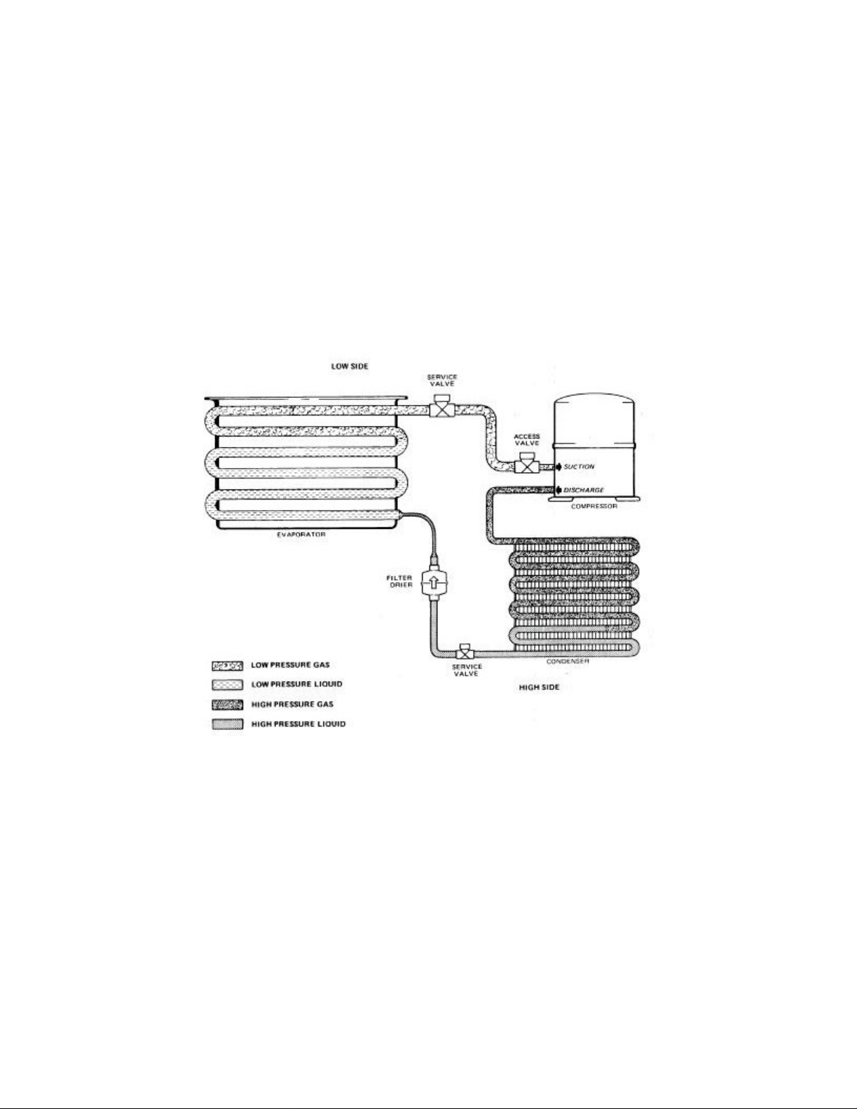
Refrigeration Cycle:
The refrigerant, HP-62 (R-404A), enters the compressor as a low pressure, heated gas. It
is converted into a high pressure, high temperature gas by the compressor and in this state
it is pumped to the condenser. A fan circulates cooling air through and around the
condenser tubing and heat is released to the atmosphere. As the refrigerant loses heat it
becomes a high pressure liquid. The filter/dryer cartridge absorbs foreign particles and
water that can enter the subsystem and reduce the refrigeration efficiency. The capillary
tube, which controls the
refrigerant causing a pressure drop across its "length. Refrigerant pressure is high
between the output of the compressor and the input to the capillary tube, and low between
the output of the capillary tube and the suction part of the compressor. The compressor
output side is the
required temperature is reached the microcomputer stops the compressor. The
refrigeration cycle is started again when the temperature exceeds the required value.
high pressure side, the suction side is the low pressure side. Once the
low pressure side of the system, restricts the flow of the
Page 2

Condensing Assembly Circuit:
The temperature control circuit signals the refrigeration cycle to start by
energizing the compressor relay, K101. This
operating voltage of
3 to 30
The logic level command signal, COOLRY (Cool Relay), is used to activate the
compressor relay and run the refrigeration system. It originates from the
Microcomptuer Board and is sent to the High Voltage Interface Board via J32 pin
7. On the High Voltage Interface Board, the driver amplifier Z2 pin 2 controls the
24
Vdc
circuit which drives the compressor relay. It is here that LED DS-3 lights
to indicate a response to the COOLRY command signal which is then sent via
J101 pin 20 to energize the compressor relay, K101. When energized, the solid
state relay allows 230V to be supplied to the compressor and fan.
Temperature Control Circuit:
There are two temperature sensors used in the rotor chamber: one measures
chamber air temperature, the other chamber floor temperature. Both sensors are
mounted in the floor of the rotor chamber. The air temperature sensor is the most
critical and requires calibration. The floor temperature sensor is used only to
anticipate rates of temperature change and close calibration is not required.
solid state 90 amp relay requires an
Vdc,
which is controlled by driver amplifier Z2 pin 2.
The sensors are two terminal integrated circuit (IC) temperature transducers that
produce an output current proportional to absolute temperature. Utilizing a
supply voltage of +12 V, the transducers act as high impedance, constant current
regulators. A constant current passes through the transducer and an increasing
temperature is detected as an increasing voltage in the circuit.
On the Microcomputer Board the voltages from the transducers are converted to a
digital value. This digital temperature value, the digital value of the preset run
temperature (as set by the operator using the TEMP °C RUN switches on the front
control panel), and the rotor parameters are used mathematically to derive the
temperature shown in the TEMP °C display of the front control panel and are
analyzed to determine whether or not the COOLRY signal is to be generated to
activate the refrigeration system.
The logic level signal SSEL (Z5 pin 19) is used to select one of the two
temperature sensors for interrogation. The selection of the sensor to be read is
under software control and each sensor is selected for 0.5 seconds. Depending on
which logic level is on Z5pin 19, 12 ±1
J3-1 (air sensor). The sensor not interrogated is disabled with 0.2 ± 0.2
Vdc are placed on J3-2 (floor sensor) or
Vdc.
An analog to digital (A/D) converter, Z20, is used to convert the analog data (3
sequential 4 BCD bit nibbles) from the temperature sensors to digital data for the
microprocessor, Z1. The TEMP signal coming from the selected temperature
sensor enters the board at J3 pin 10 and is converted from a constant current
Page 3

signal to a voltage signal by flowing through 10K resistor R36. Using voltage
reference Q2, amplifier Z21 generates a variable reference on pin 14 and can be
adjusted by R34. The resulting voltage is then buffered by Z21 pin 7, and fed into
the A/D converter input, Z20 pin 11. The data output lines (DO through D3) of
Z20 are connected to the low order 4 bits of the data bus (BDO through BD3) thus
driving addresses $0220 through $022F. Output lines MSD, LSD, NSD (Most,
Least, Next Significant Digit) are connected to the data bus (BD4 through BD6)
only during address $022E. The software is programmed to ignore the low order
four data bits for all addresses in the $0220 through $022F range, except for
$022E. During $022E, 4 BCD bits of data plus identification as Most, Next, or
Least Significant Digit, are delivered to the microprocessor. The slower,
asynchronous nature of the A/D converter is taken into consideration in the
software, which protects against acceptance of erroneous transition data.
 Loading...