

Page 1
OPERATING
INSTRUCTIONS
SORVALU RC-28S
SUPRASPEED
CENTRIFUGE
Du Pont Company
Sorvall® Instruments
Wilmington, Delaware 19898
U.S.A.
Sorvall Centrifuges
PN 59154-1
Issued August 1989
Page 2
Sorvall® Centrifuges
This manual is a guide for use of the
SORVALL® RC-28S Supraspeed® Centrifuge
Data herein has been verified and validated and is believed adequate for the intended
use of the centrifuge. If the centrifuge or procedures are used for purposes over and
above the capabilities specified herein, confirmation of their validity and suitability
should be obtained, otherwise Du Pont does not guarantee results and assumes no
obligation or liability. This publication is not a license to operate under, nor a
recommendation to infringe upon, any process patents.
NOTES,
CAUTIONS, and WARNINGS within the text of this manual are used to
emphasize important and critical instructions:
WARNING: A Warning informs the operator of a hazard or an unsafe practice that
could result in personal injury, affect the operator's health, or contaminate
the environment.
CAUTION: A Caution informs the operator of an unsafe practice that could result in
damage of equipment.
NOTE:
1988 by E.I. du Pont de Nemours & Co.
A Note highlights essential information.
ii
Page 3
Sorvall® Centrifuges Safety
Important Safety Information
Certain potentially dangerous conditions are inherent to the use of all centrifuges. To
ensure safe operation of this centrifuge, anyone using it should be aware of all safe
practices and take all precautions described below and throughout this manual.
WARNING
Use Sorvall® rotors only. Use of another manufacturer's rotor can cause rotor failure
which could result in personal injury and/or centrifuge damage.
When using radioactive, toxic, or pathogenic materials, be aware of all characteristics of
the materials and the hazards associated with them in the event leakage or rotor failure
occurs during centrifugation, in which case neither the centrifuge nor the rotor can
protect you from particles dispersed in the air. To protect
additional precautions be taken to prevent exposure to these materials, e.g., use of
controlled ventilation or isolation areas.
Always be aware of the possibility of contamination when using radioactive, toxic, or
pathogenic materials. Take all necessary precautions and use appropriate
decontamination procedures if exposure occurs.
yourself,
we recommend
Never use any material capable of producing flammable or explosive vapors.
Never exceed the maximum rated speed of the installed rotor; to do so can cause rotor
failure.
Always reduce (derate) rotor speed whenever:
• the rotor speed/temperature combination exceeds the solubility of the gradient
material and would cause it to precipitate;
• rotor compartment load exceeds the maximum allowable compartment load
specified (check this whenever average fluid density is greater than 1.2 g/ml). See
Chapter 4, Operation.
Failure to reduce rotor speed under these conditions can cause rotor failure.
CAUTION
Do not run or precool a rotor at the critical speed, as this will have a detrimental effect
on centrifuge component life. See Table 4-1, Rotor Information.
Do not operate centrifuge with a rotor out of balance. To do so can cause damage to the
centrifuge drive assembly.
Do not operate centrifuge without rotor properly installed: rotor cover must be on and
locked in place, and the rotor locked to the centrifuge drive. See rotor instruction
manual.
Locate the centrifuge on a level floor to avoid rotor imbalance during operation.
The centrifuge can be damaged if connected to the wrong voltage. Check the voltage
before plugging the centrifuge into a power source. Du Pont is not responsible for
incorrect installation.
Always maintain the centrifuge in the recommended manner. See Chapter 7,
Maintenance.
iii/iv
Page 4
Sorvall® Centrifuges Table of Contents
Table of Contents
Page
Safety Information iii
Chapter 1. DESCRIPTION
General Description 1-1
Centrifuge Specifications 1-2
Centrifuge Features 1-3
System Descriptions 1-5
Chapter 2. INSTALLATION
Inspection 2-1
Location 2-1
Ambient Temperature 2-2
Leveling 2-2
Electrical 2-2
Chapter 3. CONTROLS
Control Panel 3-1
PROGRAM Key Functions & Display Screens 3-3
CALCULATE Key Functions & Display Screens 3-9
DIAGNOSTICS Key Functions & Display Screens 3-9
Chapter 4. OPERATION
Understanding the Centrifuge Controls 4-1
Turning the Centrifuge On 4-1
Normal Run 4-1
Slow Start/Slow Stop 4-3
RCF Run 4-5
Key#Code 4-6
Zonal Run 4-7
Hold Run 4-8
fctfdt Run 4-9
Programmed Run 4-10
Control Panel Lock 4-11
Precool/Preheat 4-12
Reducing Speed for Rotor Compartment Loads in
Excess of Design Mass 4-12
Page 5
Table of Contents Sorvall® Centrifuges
Table of Contents (continued)
Page
Chapter 5. CALCULATOR
Calculator Display Screens 5-1
Calculate Speed/RCF for Rotor Time/fo^dt 5-1
Calculate Speed/RCF at a Radius 5-2
Calculate K Factor 5-2
Calculate Rotor Conversion/Time 5-2
Chapter 6. TROUBLESHOOTING & DIAGNOSTICS
Display Messages 6-1
Diagnostics:
General 6-5
Screen 1, Faults 6-6
Screen 2 6-7
Screen 3 6-9
How to Assign or Change a Key# 6-9
How to Change Slow Start/Slow Stop Transition Speed 6-12
Chapter 7. MAINTENANCE
Maintenance Schedule 7-1
Cleaning:
Rotor Chamber 7-2
Tapered Drive Spindle 7-2
Cabinet 7-2
Control Panel 7-2
Door Seal 7-2
Refrigeration System Condenser 7-4
Air Louvers 7-4
Lubrication 7-4
Changing the Vacuum Pump Oil & Mist Eliminator Filter 7-4
Emergency Sample Recovery 7-8
Test of RUN Display Lights & Control Panel Indicators 7-10
Parts Ordering Information 7-11
Service Decontamination Policy 7-11
APPENDIX
Vacuum Pump Oil Specifications
Warranty
Glossary
Index
Program Log Cards
Decontamination Certificates
VI
Page 6
Sorvair Centrifuges
Table of Contents
List of Illustrations
Figure
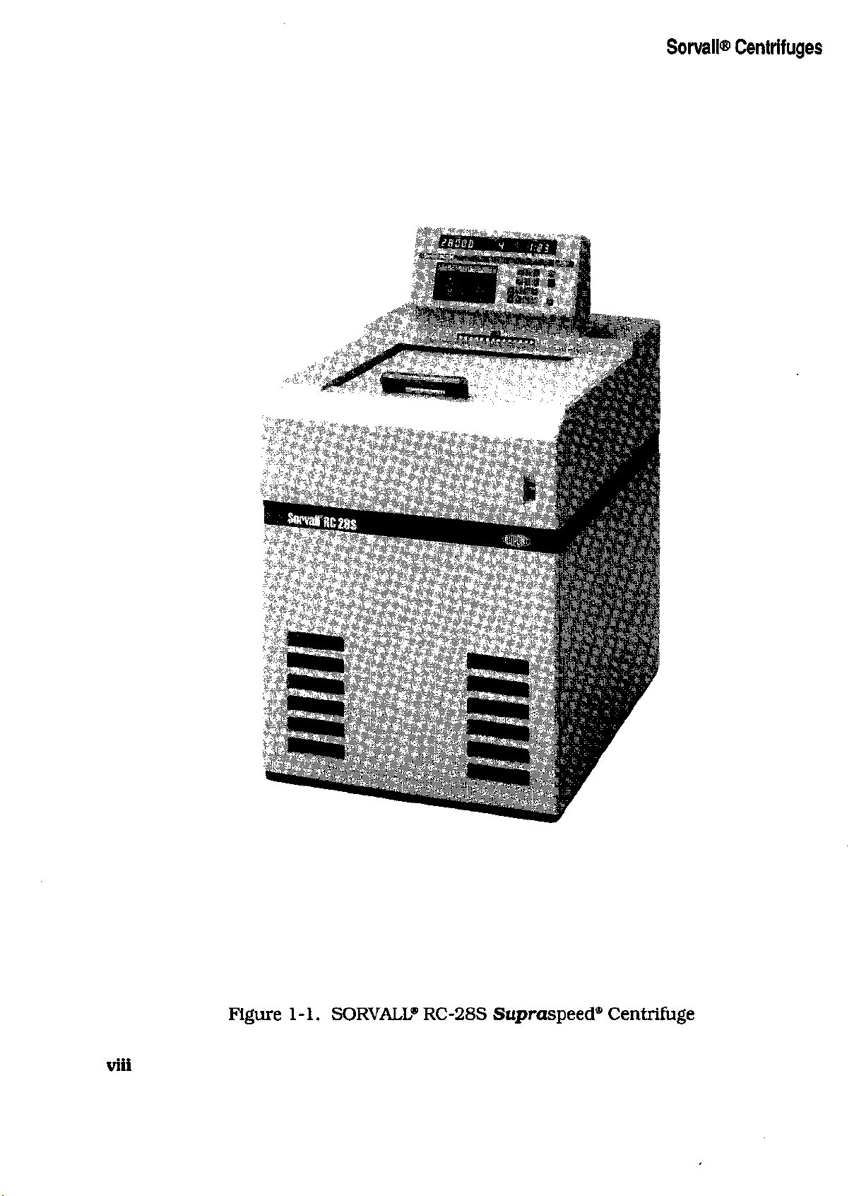
1-1. SORVALL® RC-28S Supraspeed® Centrifuge viii
2-1.
Centrifuge Dimensions 2-1
2-2.
Leveling Adjustment 2-2
3-1.
Control Panel 3-2
7-1.
Door Seal Removal 7-3
7-2. Parts Identification, Vacuum Pump Oil Change 7-6
7-3.
Door Interlock Override 7-9
7-4. Vacuum Release Solenoid Valve Location 7-9
List of Tables
Table
4-1.
Rotor Information 4-4
6-1.
DIAGNOSTICS, Screen 2 Fields 6-7
6-2. DIAGNOSTICS, Screen 2 Operations 6-7
6-3.
DIAGNOSTICS, Screen 3 Fields 6-8
7-1.
Maintenance Schedule 7-1
Page
Page
vii
Page 7
Sorvall® Centrifuges
viii
Figure 1-1. SORVALL® RC-28S Supraspeed® Centrifuge
Page 8
Sorvall®Centrifuges Description
Chapter 1
DESCRIPTION
This manual provides you with the information you need to install, operate and
maintain your SORVALL® RC-28S Supraspeed® Centrifuge. If you encounter any
problem concerning either operation or maintenance that is not covered in the manual,
please telephone Du Pont for assistance. In the United States, call toll free
(800)551-2121.
SORVALL® Products.
General Description
The Sorvall® RC-28S Supraspeed® Centrifuge defines a new class of centrifuge that
brings an unparalleled level of performance to centrifugation. Created from the latest
design technology, it incorporates usability, dependability, and safety with an extremely
versatile speed range to set a new standard in value. When used with a Sorvall®
Supraspeed® rotor, the RC-28S can reach a top speed of 28 000 rpm with a maximum
g force of 100 095. At 100 095 x g you can perform applications in the RC-28S that
previously required an ultracentrifuge. In addition to the Supraspeed® rotors designed
for use with the RC-28S, the RC-28S accepts all Sorvall® superspeed rotors, increasing
its usefulness by making it capable of a wide range of applications.
Outside the United States, contact the distributor or agent for
The centrifuge is microcomputer controlled and designed to be user friendly. It can be
operated using basic parameters only or you can decide to use its special features.
Because of this versatility and its user-friendliness, it can easily be operated by
inexperienced persons learning centrifugation methods or by experienced persons
experimenting with new methods.
The brushless dc drive which offers the optimum in centrifuge drive performance is one
distinct feature of the RC-28S. Other features of the centrifuge are: automatic rotor
recognition; programmability; RCF and
for sample reorientation; overtemperature control; a control panel lock to prevent run
parameters from being changed; and a built-in calculator that can be used to perform
centrifugation calculations, including conversions between RCF and speed, time and
fco2dt or the calculation of K factors and run times when conversion of published run
parameters is desired.
The centrifuge also has extensive diagnostic routines that allow the user to identify
system malfunctions and perform maintenance and repair procedures.
For more on the features of the RC-28S, plus more on the centrifuge drive and other
systems, read the table on the next two pages and the descriptive paragraphs that follow
the table.
fco2dt
control; slow start and slow stop control
1-1
Page 9
Description
Centrifuge Specifications
Son/all® Centrifuges
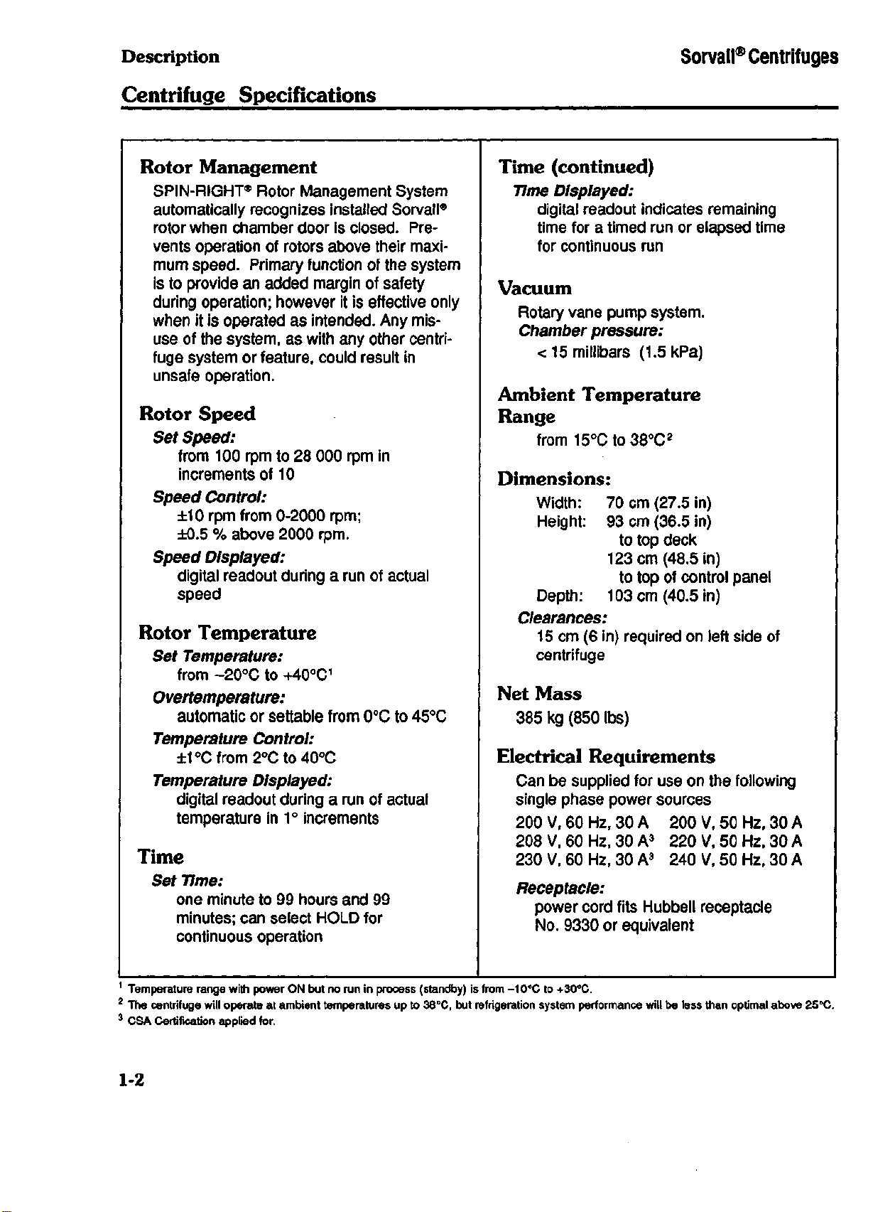
Rotor Management
SPIN-RIGHT® Rotor Management System
automatically recognizes installed Sorvall®
rotor when chamber door is closed. Pre-
vents operation of rotors above their maxi-
mum speed. Primary function of the system
is to provide an added margin of safety
during operation; however it is effective only
when it is operated as intended. Any misuse of the system, as with any other centrifuge system or feature, could result in
unsafe operation.
Rotor Speed
Set Speed:
from 100 rpm to 28 000 rpm in
increments of 10
Speed Control:
±10 rpm from 0-2000 rpm;
±0.5 % above 2000 rpm.
Speed Displayed:
digital readout during a run of actual
speed
Rotor Temperature
Set Temperature:
from -20°C to +40°C
Overtemperature:
automatic or settable from 0°C to 45°C
Temperature Control:
±10Cfrom2°Cto40°C
Temperature Displayed:
digital readout during a run of actual
temperature in 1 ° increments
1
Time
Set Time:
one minute to 99 hours and 99
minutes; can select HOLD for
continuous operation
Time (continued)
Time Displayed:
digital readout indicates remaining
time for a timed run or elapsed time
for continuous run
Vacuum
Rotary vane pump system.
Chamber pressure:
< 15 millibars (1.5 kPa)
Ambient Temperature
Range
from 15°Cto38°C
2
Dimensions:
Width:
Height: 93 cm (36.5 in)
Depth:
Clearances:
15 cm (6 in) required on left side of
centrifuge
70 cm (27.5 in)
to top deck
123 cm (48.5 in)
to top of control panel
103 cm (40.5 in)
Net Mass
385 kg (850 lbs)
Electrical Requirements
Can be supplied for use on the following
single phase power sources
200 V, 60 Hz, 30 A 200 V, 50 Hz, 30 A
208 V, 60 Hz, 30 A3 220 V, 50 Hz, 30 A
230 V, 60 Hz, 30 A3 240 V, 50 Hz, 30 A
Receptacle:
power cord fits Hubbell receptacle
No.
9330 or equivalent
1
Temperature range with power ON but no run in process (standby) is from -10°C to +30°C.
2
The centrifuge will operate at ambient temperatures up to 38°C, but refrigeration system performance will be less than optimal above 25°C.
3
CSA Certification applied for.
1-2
Page 10
Sorvall® Centrifuges
Description
Centrifuge Features
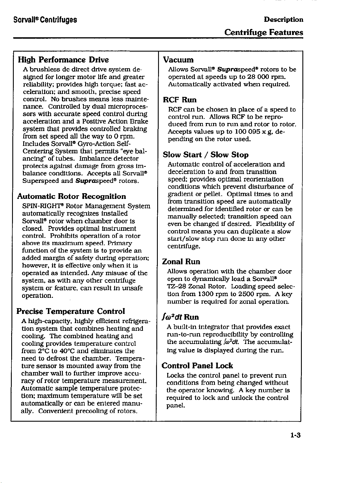
High Performance Drive
A brushless dc direct drive system de-
signed for longer motor life and greater
reliability; provides high torque; fast acceleration; and smooth, precise speed
control. No brushes means less maintenance. Controlled by dual microprocessors with accurate speed control during
acceleration and a Positive Action Brake
system that provides controlled braking
from set speed all the way to 0 rpm.
Includes Sorvall® Gyro-Action
Centering System that permits "eye balancing" of tubes. Imbalance detector
protects against damage from gross imbalance conditions. Accepts all Sorvall®
Superspeed and Supraspeed® rotors.
Self-
Automatic Rotor Recognition
SPIN-RIGHT® Rotor Management System
automatically recognizes installed
Sorvall® rotor when chamber door is
closed. Provides optimal instrument
control. Prohibits operation of a rotor
above its maximum speed. Primary
function of the system is to provide an
added margin of safety during operation;
however, it is effective only when it is
operated as intended. Any misuse of the
system, as with any other centrifuge
system or feature, can result in unsafe
operation.
Vacuum
Allows Sorvall® Supraspeed® rotors to be
operated at speeds up to 28 000 rpm.
Automatically activated when required.
RCF Run
RCF can be chosen in place of a speed to
control run. Allows RCF to be reproduced from run to run and rotor to rotor.
Accepts values up to 100 095 x g, de-
pending on the rotor used.
Slow Start / Slow Stop
Automatic control of acceleration and
deceleration to and from transition
speed; provides optimal reorientation
conditions which prevent disturbance of
gradient or pellet. Optimal times to and
from transition speed are automatically
determined for identified rotor or can be
manually selected; transition speed can
even be changed if desired. Flexibility of
control means you can duplicate a slow
start/slow stop run done in any other
centrifuge.
Zonal Run
Allows operation with the chamber door
open to dynamically load a Sorvall®
TZ-28 Zonal Rotor. Loading speed selection from 1300 rpm to 2500 rpm. A key
number is required for zonal operation.
Precise Temperature Control
A high-capacity, highly efficient refrigeration system that combines heating and
cooling. The combined heating and
cooling provides temperature control
from 2°C to 40°C and eliminates the
need to defrost the chamber. Temperature sensor is mounted away from the
chamber wall to further improve accuracy of rotor temperature measurement.
Automatic sample temperature protec-
tion; maximum temperature will be set
automatically or can be entered manually. Convenient precooling of rotors.
fco2dt Run
A built-in integrator that provides exact
run-to-run reproducibility by controlling
the accumulating
ing value is displayed during the run.
fo)2dt.
The accumulat-
Control Panel Lock
Locks the control panel to prevent run
conditions from being changed without
the operator knowing. A key number is
required to lock and unlock the control
panel.
1-3
Page 11
Description
Centrifuge Features
Sorvall® Centrifuges
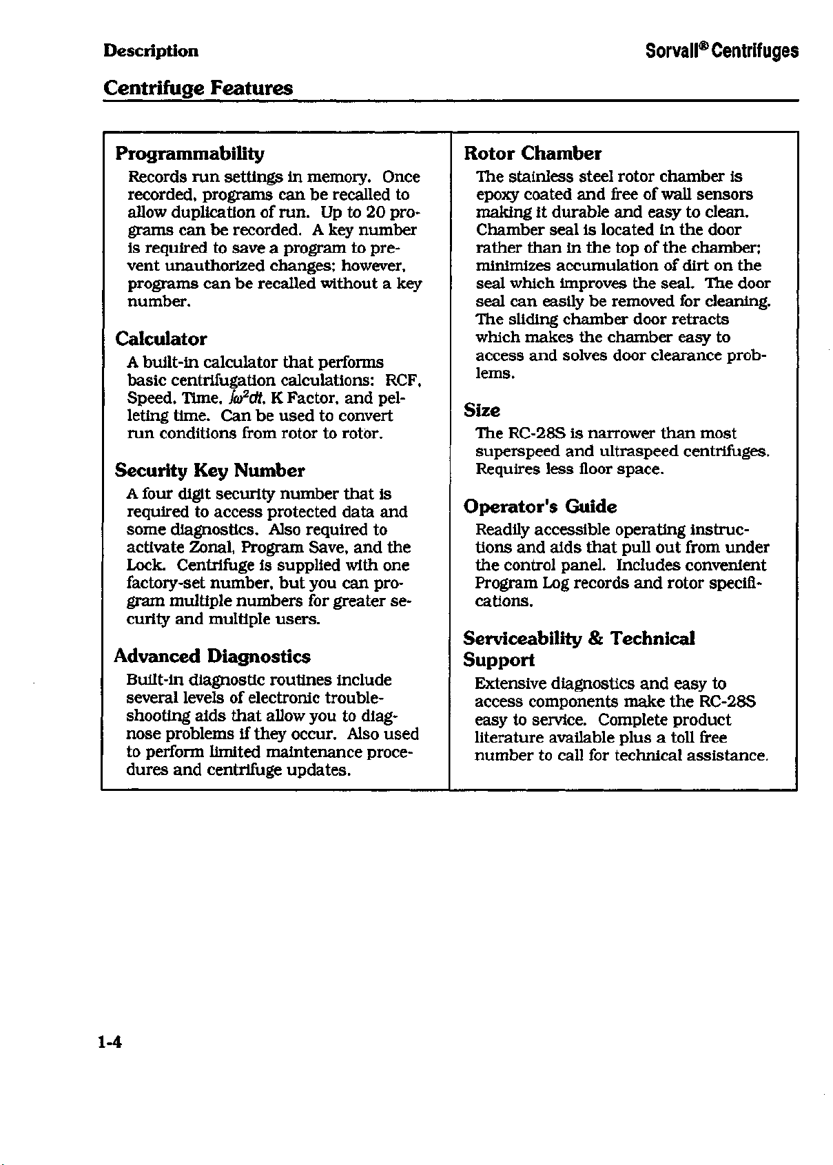
Programmability
Records run settings in memory. Once
recorded, programs can be recalled to
allow duplication of run. Up to 20 programs can be recorded. A key number
is required to save a program to pre-
vent unauthorized changes; however,
programs can be recalled without a key
number.
Calculator
A built-in calculator that performs
basic centrifugation calculations: RCF,
Speed, Time,
leting time. Can be used to convert
run conditions from rotor to rotor.
S(o2dU
K Factor, and pel-
Security Key Number
A four digit security number that is
required to access protected data and
some diagnostics. Also required to
activate Zonal, Program Save, and the
Lock. Centrifuge is supplied with one
factory-set number, but you can program multiple numbers for greater security and multiple users.
Advanced Diagnostics
Built-in diagnostic routines include
several levels of electronic troubleshooting aids that allow you to diagnose problems if they occur. Also used
to perform limited maintenance procedures and centrifuge updates.
Rotor Chamber
The stainless steel rotor chamber is
epoxy coated and free of wall sensors
making it durable and easy to clean.
Chamber seal is located in the door
rather than in the top of the chamber;
minimizes accumulation of dirt on the
seal which improves the seal. The door
seal can easily be removed for cleaning.
The sliding chamber door retracts
which makes the chamber easy to
access and solves door clearance problems.
Size
The RC-28S is narrower than most
superspeed and ultraspeed centrifuges.
Requires less floor space.
Operator's Guide
Readily accessible operating instructions and aids that pull out from under
the control panel. Includes convenient
Program Log records and rotor specifications.
Serviceability & Technical
Support
Extensive diagnostics and easy to
access components make the RC-28S
easy to service. Complete product
literature available plus a toll free
number to call for technical assistance.
1-4
Page 12
Sorvall®Centrifuges Description
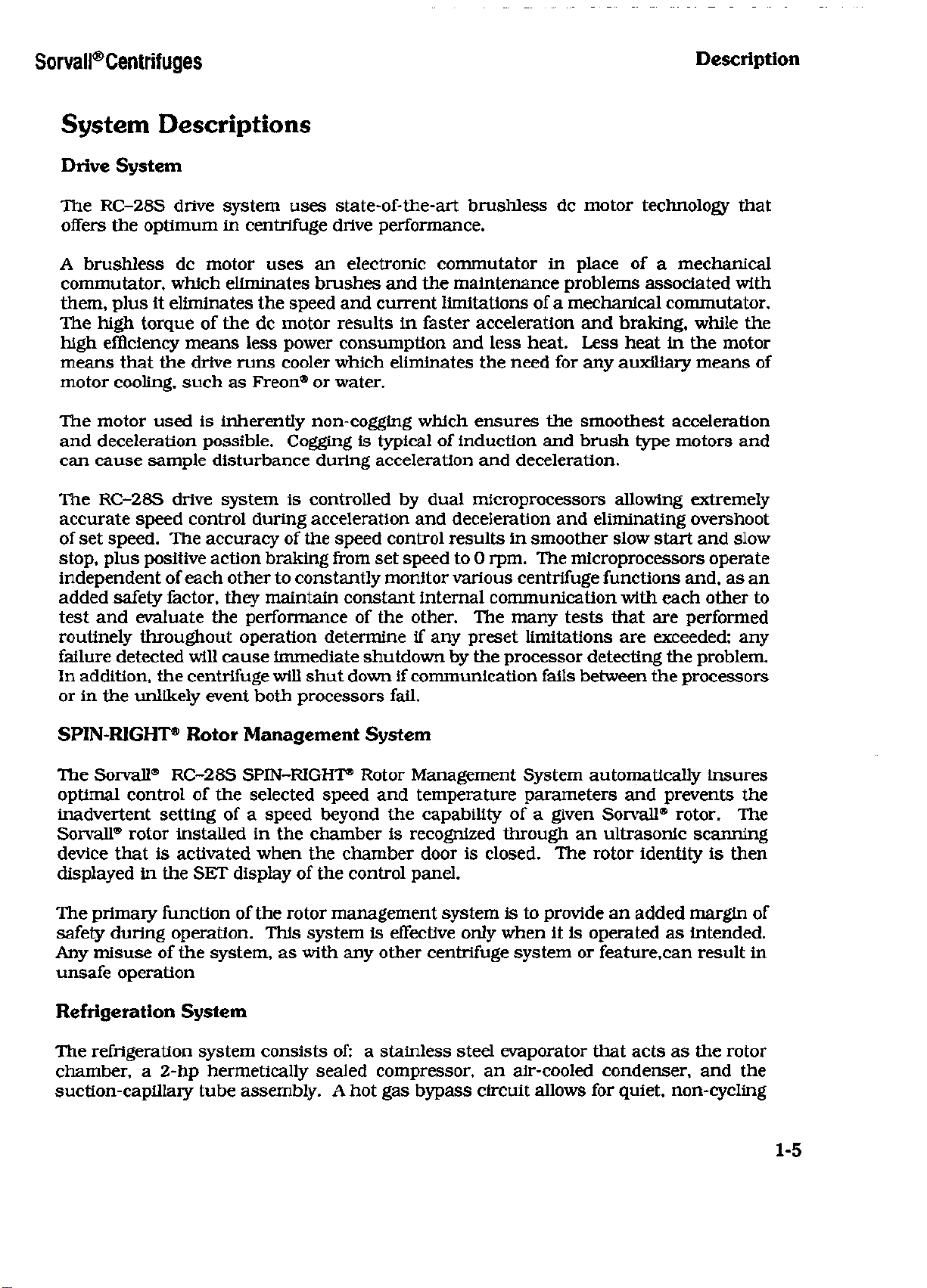
System Descriptions
Drive System
The RC-28S drive system uses state-of-the-art brushless dc motor technology that
offers the optimum in centrifuge drive performance.
A brushless dc motor uses an electronic commutator in place of a mechanical
commutator, which eliminates brushes and the maintenance problems associated with
them, plus it eliminates the speed and current limitations of a mechanical commutator.
The high torque of the dc motor results in faster acceleration and braking, while the
high efficiency means less power consumption and less heat. Less heat in the motor
means that the drive runs cooler which eliminates the need for any auxiliary means of
motor cooling, such as Freon® or water.
The motor used is inherently non-cogging which ensures the smoothest acceleration
and deceleration possible. Cogging is typical of induction and brush type motors and
can cause sample disturbance during acceleration and deceleration.
The RC-28S drive system is controlled by dual microprocessors allowing extremely
accurate speed control during acceleration and deceleration and eliminating overshoot
of set speed. The accuracy of the speed control results in smoother slow start and slow
stop,
plus positive action braking from set speed to 0 rpm. The microprocessors operate
independent of each other to constantly monitor various centrifuge functions and, as an
added safety factor, they maintain constant internal communication with each other to
test and evaluate the performance of the other. The many tests that are performed
routinely throughout operation determine if any preset limitations are exceeded; any
failure detected will cause immediate shutdown by the processor detecting the problem.
In addition, the centrifuge will shut down if communication fails between the processors
or in the unlikely event both processors fail.
SPIN-RIGHT® Rotor Management System
The Sorvall® RC-28S SPIN-RIGHT® Rotor Management System automatically insures
optimal control of the selected speed and temperature parameters and prevents the
inadvertent setting of a speed beyond the capability of a given Sorvall® rotor. The
Sorvall® rotor installed in the chamber is recognized through an ultrasonic scanning
device that is activated when the chamber door is closed. The rotor identity is then
displayed in the SET display of the control panel.
The primary function of the rotor management system is to provide an added margin of
safety during operation. This system is effective only when it is operated as intended.
Any misuse of the system, as with any other centrifuge system or feature,can result in
unsafe operation
Refrigeration System
The refrigeration system consists of: a stainless steel evaporator that acts as the rotor
chamber, a 2-hp hermetically sealed compressor, an air-cooled condenser, and the
suction-capillary tube assembly. A hot gas bypass circuit allows for quiet, non-cycling
1-5
Page 13
Description Sorvall®Centrifuges
compressor operation as well as improved temperature control and frost-free operation.
The refrigeration system is factory charged with Freon® 502.
The desired run temperature is entered on the control panel and is maintained by the
system electronics which cycles the hot gas circuit as required. If desired, a maximum
temperature can be entered on the control panel; if a value is not entered manually, the
maximum temperature will default to +5°C above set temperature. Any failure causing
the temperature to exceed the maximum setting will result in the termination of the run
and a corresponding message will be displayed on the control panel to alert the
operator.
Vacuum System
The vacuum system includes a direct drive vacuum pump, an air-inlet solenoid (bleed)
valve, mist eliminator, the evaporator chamber, and interconnecting tubes and fittings.
Reduced rotor chamber pressure is sensed by a Pirani convection gauge located at the
pump inlet manifold and monitored by the machine control microprocessor. When
activated, this system provides a vacuum level between 1 and 15 millibars.
The vacuum system is automatically activated only when the set speed is higher than
the top air speed of one of the Sorvall® Supraspeed® rotors designed specifically for use
with the RC-28S.
In the event of a vacuum loss or insufficient vacuum, a message will appear in the
control panel SET display to notify the operator. In an emergency, such as a power
failure, when sample recovery is desirable, the chamber door can be opened manually
(see Chapter 7 for procedure).
1-6
Page 14
Sorvall® Centrifuges
Installation
Chapter 2
INSTALLATION
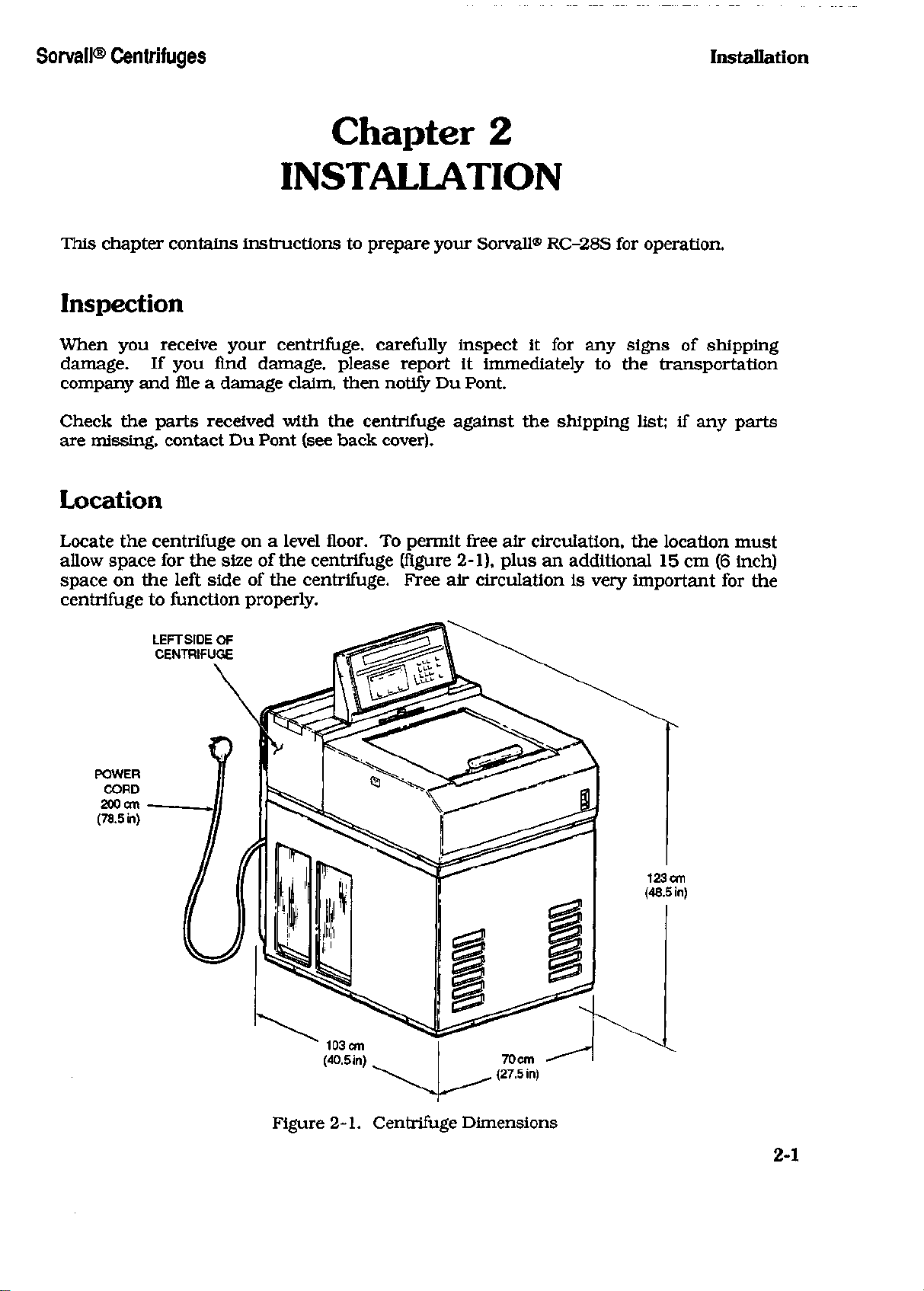
This chapter contains instructions to prepare your Sorvall® RC-28S for operation.
Inspection
When you receive your centrifuge, carefully inspect it for any signs of shipping
damage. If you find damage, please report it immediately to the transportation
company and file a damage claim, then notify Du Pont.
Check the parts received with the centrifuge against the shipping list; if any parts
are missing, contact Du Pont (see back cover).
Location
Locate the centrifuge on a level floor. To permit free air circulation, the location must
allow space for the size of the centrifuge (figure 2-1), plus an additional 15 cm (6 inch)
space on the left side of the centrifuge. Free air circulation is very important for the
centrifuge to function properly.
LEFTSIDE OF
CENTRIFUGE
POWER
CORD
200cm -
(78.5 in)
123 cm
(48.5 in)
Figure 2-1. Centrifuge Dimensions
2-1
Page 15
Installation
Son/all® Centrifuges
Ambient Temperature
An ambient temperature range of 15°C to 38°C must be maintained. If the inlet air
temperature is above 25°C, the centrifuge will not maintain low temperatures at
high speeds.
Leveling
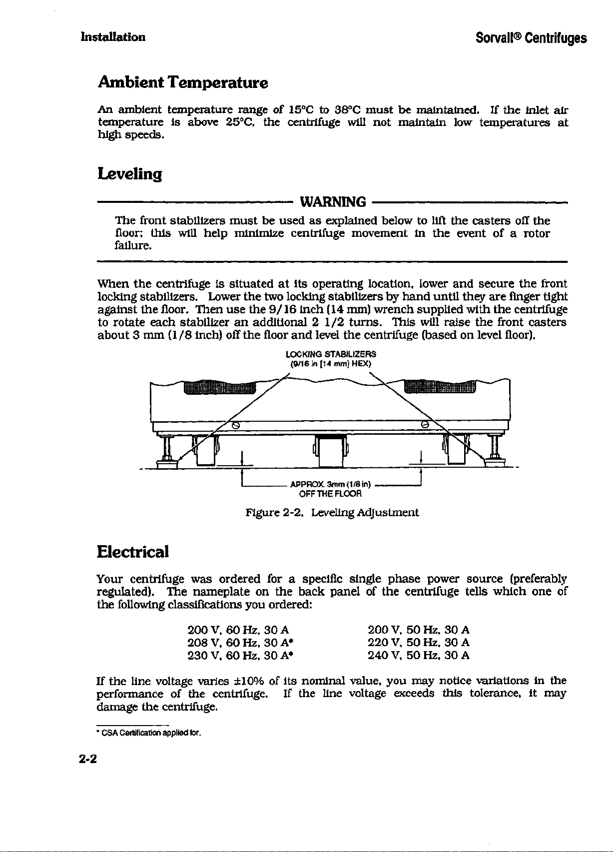
WARNING
The front stabilizers must be used as explained below to lift the casters off the
floor; this will help minimize centrifuge movement in the event of a rotor
failure.
When the centrifuge is situated at its operating location, lower and secure the front
locking stabilizers. Lower the two locking stabilizers by hand until they are finger tight
against the floor. Then use the 9/16 inch (14 mm) wrench supplied with the centrifuge
to rotate each stabilizer an additional 2 1/2 turns. This will raise the front casters
about 3 mm (1/8 inch) off the floor and level the centrifuge (based on level floor).
LOCKING STABILIZERS
(9/16 in [14 mm] HEX)
APPROX. 3mm (1/8 in)
OFF THE FLOOR
Figure 2-2. Leveling Adjustment
Electrical
Your centrifuge was ordered for a specific single phase power source (preferably
regulated). The nameplate on the back panel of the centrifuge tells which one of
the following classifications you ordered:
200 V, 60 Hz, 30 A
208 V, 60 Hz, 30 A*
230 V, 60 Hz, 30 A*
200 V, 50 Hz, 30 A
220 V, 50 Hz, 30 A
240 V, 50 Hz, 30 A
If the line voltage varies ±10% of its nominal value, you may notice variations in the
performance of the centrifuge. If the line voltage exceeds this tolerance, it may
damage the centrifuge.
* CSA Certification applied for.
2-2
Page 16
Sorvall® Centrifuges installation
CAUTION
The centrifuge can be damaged if connected to the wrong voltage. Check
the voltage before plugging the centrifuge into any power source. DuPont
is not responsible for improper installation.
The centrifuge is equipped with a 3-wire power cord with a 3-prong cap, including
ground connection, to fit Hubbell receptacle No. 9330 or equivalent.
To connect the centrifuge to a voltage other than what is specified on the nameplate, the
centrifuge will have to be rewired and the power cord may have to be replaced. In this
case,
contact DuPont to have a Service Representative do the rewiring.
The ON/OFF main power switch is a 30 A circuit breaker, therefore a separate line
disconnect switch is not needed unless required by local codes.
2-3/2-4
Page 17
Sorvall® Centrifuges Controls
Chapter 3
CONTROLS
This chapter provides:
• a detailed description of the RC-28S controls;
• a brief description of the built-in calculator; and
• a brief description of the diagnostic routines.
For step-by-step operating instructions see Chapter 4, and for further information
on the calculator and the diagnostics, see Chapters 5 and 6.
NOTE
A convenient Operator's Guide containing simplified instructions is located
under the centrifuge control console.
Control Panel
The RC-28S is easy to use. All commands are entered from the convenient keypad
on the control panel and the set and run parameters are visible in the displays. All
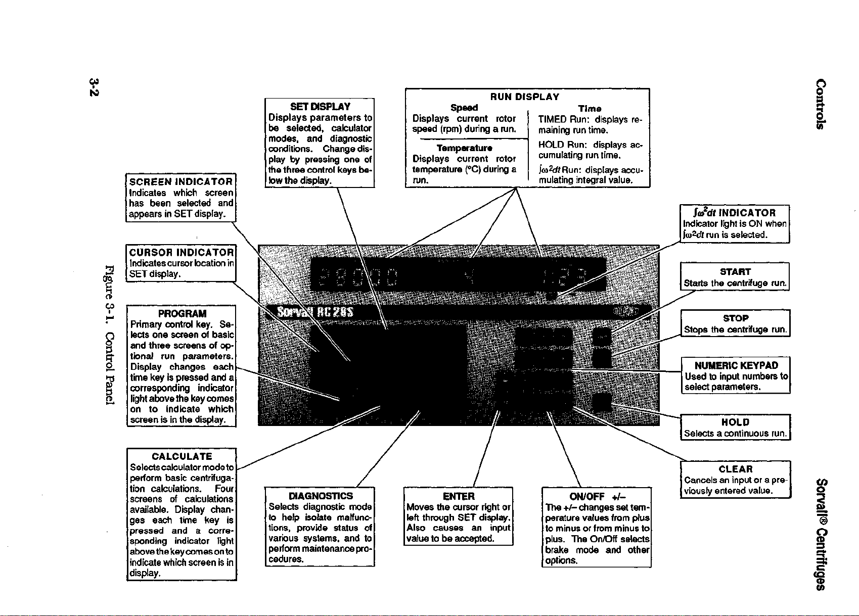
selected parameters can be locked to prevent changes to run settings. Figure 3-1
on the next page shows the RC-28S control panel and gives a brief description of
the keys and displays. A complete description follows the illustration.
Set Display
The SET display is the lower display that changes by pressing the PROGRAM,
CALCULATE or DIAGNOSTICS key to show various screens of parameters or
operations. A cursor in the SET display indicates the field where the next input
character will appear. Lights below the display indicate the position of the cursor.
Run Display
The RUN display includes the three upper displays that show actual speed,
temperature, and time or Jco2dt during a run.
3-1
Page 18
CO
SCREEN INDICATOR
Indicates which screen
has been selected and
appears in SET display.
CURSOR INDICATOR
Indicates cursor location in
SET display.
2
1
SET DISPLAY
Displays parameters to
be selected, calculator
modes, and diagnostic
conditions. Change display by pressing one of
the three control keys be-
low the display.
RUN DISPLAY
Speed
Displays current rotor
speed (rpm) during a run.
Temperature
Displays current rotor
temperature (°C) during a
run.
Time
TIMED Run: displays re-
maining run time.
HOLD Run: displays ac-
cumulating run time.
displays accu-
mulating integral value.
Ja/WflNDICATOR
Indicator light is ON when
lco2dt run is selected.
START
Starts the centrifuge run.
O
O
a
PROGRAM
Primary control key. Selects one screen of basic
and three screens of op-
B
tional run parameters.
Display changes each
I
time key is pressed and a
corresponding indicator
light above the key comes
on to indicate which
screen is in the display.
CALCULATE
Selects calculator mode to
perform basic centrifugation calculations. Four
screens of calculations
available. Display changes each time key is
pressed and a corresponding indicator light
above the key comes on to
indicate which screen is in
display.
DIAGNOSTICS
Selects diagnostic mode
to help isolate malfunctions,
provide status of
various systems, and to
perform maintenance procedures.
ENTER
Moves the cursor right or
left through SET display.
Also causes an input
value to be accepted.
ON/OFF +/-
The +/- changes set temperature values from plus
to minus or from minus to
plus.
The On/Off selects
brake mode and other
options.
STOP
Stops the centrifuge run.
NUMERIC KEYPAD
Used to input numbers to
select parameters.
HOLD
Selects a continuous run.
CLEAR
Cancels an input or a previously entered value.
CO
o
5
(D
CO
Page 19
Sorvall® Centrifuges
Controls
Description of Display & Key Functions
v
j v j V j
Cancels
the entry
again,
Starts
Stops
the
the
the
The numeric keypad
select parameter values.
The ENTER keys cause
accepted, plus they cause
the right
On/Off
word
On or Off
of
the SET
the temperature value from positive
negative
an
input
is set to
previously entered value
centrifuge
centrifuge
or a
previously entered value. When
zero
(0) and a new
run.
run.
is
or to the
is
used
to
is
used
to
left through
to
select options. When pressed,
will appear
display.
positive.
value
restored.
input numbers from
an
input value
the
cursor
the SET
in the
The +/- is
can be
input. When pressed
appropriate field
used only
to
the key is
0 to 9 to
to
move
display.
to
negative
pressed,
to be
to
the
change
or
Selects a continuous
the
SET
display
is pressed,
show accumulating
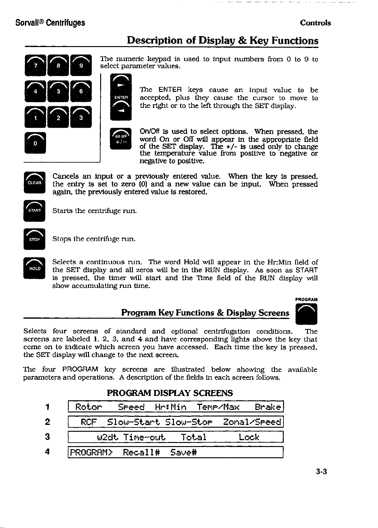
Selects four screens
screens
come
the
The four PROGRAM
parameters
are
labeled
on to
SET
indicate which screen
display will change
and
1
2
the
1, 2, 3, and 4 and
operations. A description
Rotor Speed Hr:Min Tenp/Max Brake
RCF Slow-Start Slow-Stop Zonal/Speed
3
run. The
and all
timer will start
run
zeros will
time.
Program
of
standard
you
key
to the
screens
next screen.
word Hold will appear
be in the RUN
and the
Key
and
optional centrifugation conditions.
have corresponding lights above
have accessed. Each time
are
illustrated below showing
of the
Time field
Functions & Display Screens
fields
in
each screen follows.
in the
display.
of the RUN
As
the key is
PROGRAM DISPLAY SCREENS
w2dt Tine-out Total Lock
HnMin field
soon
as
START
display will
PROGRAM
The
the key
the
available
that
pressed,
of
4
PROGRflM> Recal1# Save#
3-3
Page 20
Controls Sorvall® Centrifuges
PROGRAM
Program Key Functions & Display Screens
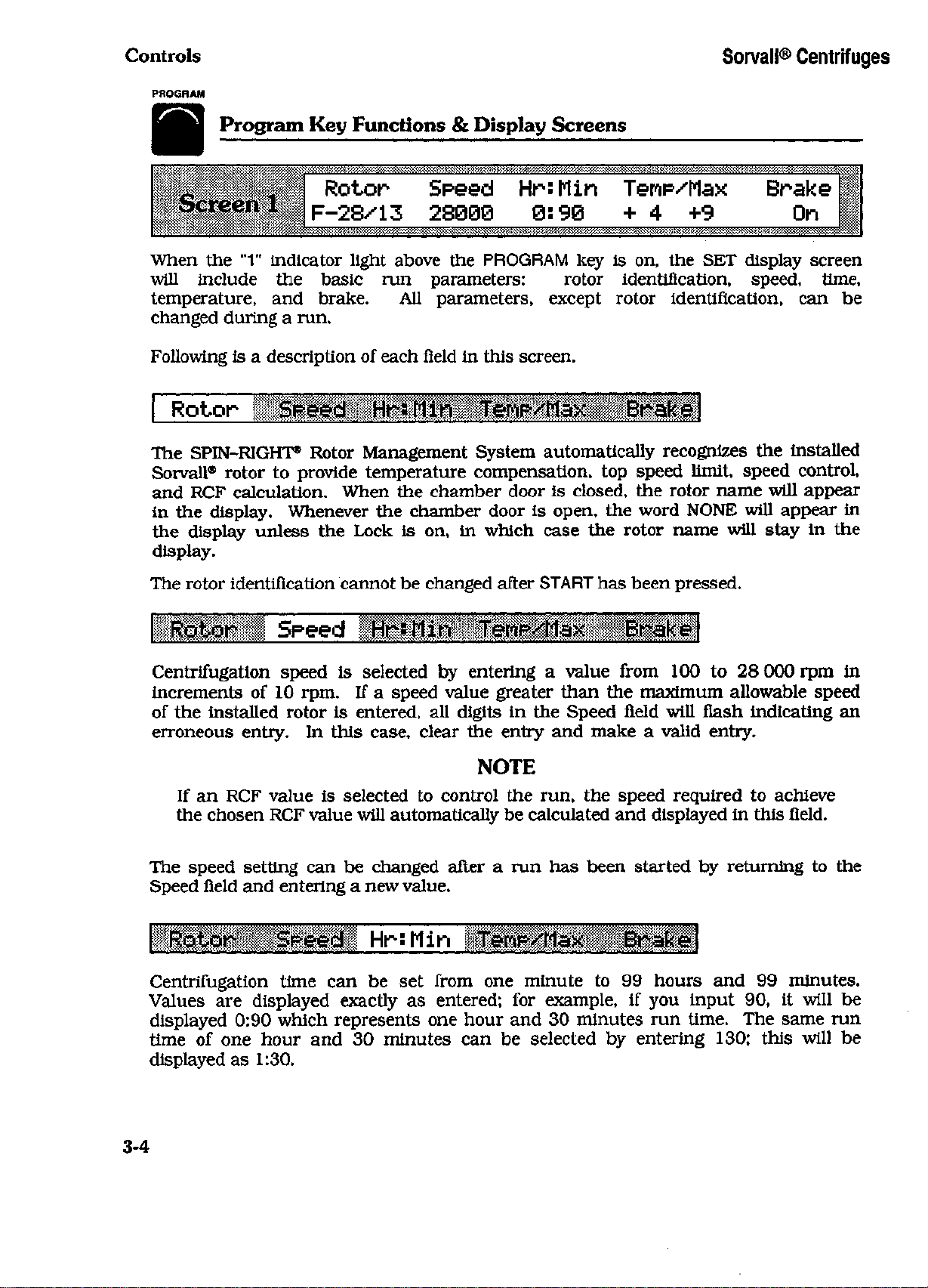
Rotor Speed HrsMin Temp^Max Brake
Screen
1
F-28^13 23000
0:90
+4+9
On
When the "1" indicator light above the PROGRAM key
will include
temperature,
changed during a run.
Following is a description of each field in this screen.
the
and
basic
brake.
run
All
parameters: rotor identification, speed, time,
parameters, except rotor identification,
is
on, the SET display screen
can be
Rotor Speed HrsMin TeMp/Max Brake
The SPIN-RIGHT® Rotor Management System automatically recognizes the installed
Sorvall® rotor
and RCF calculation. When the chamber door
in the display. Whenever the chamber door
the display unless the Lock
display.
The rotor identification cannot be changed after START has been pressed.
Iliiiiiil Speed
Centrifugation speed
increments
of the installed rotor
erroneous entry.
to
of
provide temperature compensation, top speed limit, speed control,
is
closed, the rotor name will appear
is
open, the word NONE will appear
is
on,
in
is
10 rpm.
is
In
which case the rotor name will stay
selected
If a
entered, all digits
this case, clear the entry and make a valid entry.
by
entering a value from 100
speed value greater than the maximum allowable speed
in
the Speed field will flash indicating an
to
28 000 rpm
in
in
the
in
NOTE
If an RCF value
the chosen RCF value will automatically be calculated and displayed in this field.
The speed setting can
Speed field and entering a new value.
is
be
selected
to
control the run, the speed required
changed after a run has been started by returning
to
achieve
Rotor Speed HrsMin TerwMax Brake
Centrifugation time can
Values are displayed exactly
displayed 0:90 which represents one hour and 30 minutes run time. The same run
time
of
one hour and
displayed as 1:30.
3-4
be set
as
30
minutes can
from one minute
entered;
for
be
example,
selected
to 99
if
by
hours and
you input 90,
entering 130; this will
99
minutes.
it
to
will
the
be
be
Page 21
Sorvall® Centrifuges Controls
PROGRAM
As soon
timer will begin when START
from
HOLD will appear
(0)
timer will begin after
Time
entering a new value.
as an
set
value
and
will show accumulating
can be
entry
to
changed after
is
zero
in the SET
made,
to
show remaining
the
rotor
the run has
Program
the
is
pressed
display
run
Key
entered value will appear
and the RUN
time. When operating
has
been loaded
Functions & Display Screens
and the RUN
run
time.
started
by
display value will count down
If
display value will begin
and the
returning
HOLD
NOTE
If
the
integrator
accumulated. During
integral value
HnMin field.
started.
During a timed
value will
be
displayed
is On, the run
a run, the RUN
and the SET
The
run
integrator cannot
with
no
in the
will
end
when
display will show accumulating
be
turned
preselected integral value,
G&dt
Total field
of
the
selected integral value
display will show
Off (or On)
Screen
3.
the
Rotor 5r*eed HrsMin Tenp/Max Ilillfil
. i
in the
in the
to the
after
RUN display.
is
selected,
Zonal mode,
chamber door closed.
Hr:Min field
the
accumulating
run
time
a run has
accumulating integral
the
at
has
in the
been
The
word
zero
the
and
There
centrifugation temperature;
protection limit.
Centrifugation temperature
Acceptable
value
Temp value
to 0°C).
Max temperature
desired value, however,
operation,
value until
are two
is not
If
the
temperature shown
value (shown
indicated temperature
Temp value
the Max
rotor temperature settings.
Max
the
temperature values
entered,
is -6°C or
or at
rotor
the
lower
in the SET
0°C.
can be
temperature setting should
has
and
changed
it
cooled
the
other.
can be set
value will default
in
which case
Max,
from -20°C
are
from
NOTE
in RUN
display),
will decrease
must
to the
display
Max
as
by
moving
be at
least
selected temperature.
The
to 5°C
the Max
is 5°C or
temperature will remain
2°
first
one,
selects
0°C to
rotor cools until
the
not be
the
sample overtemperature
to
+40°C
+45°C.
above
temperature will always default
cursor
above
the
more above entered Temp
to Max and
set
Temp value.
changed from
Brak
Temp, selects desired
in
increments
If a Max
Temp value (unless
it is 5°
e
of 1°C.
temperature
3°C
above
above
entering
the
set
For
default
the
best
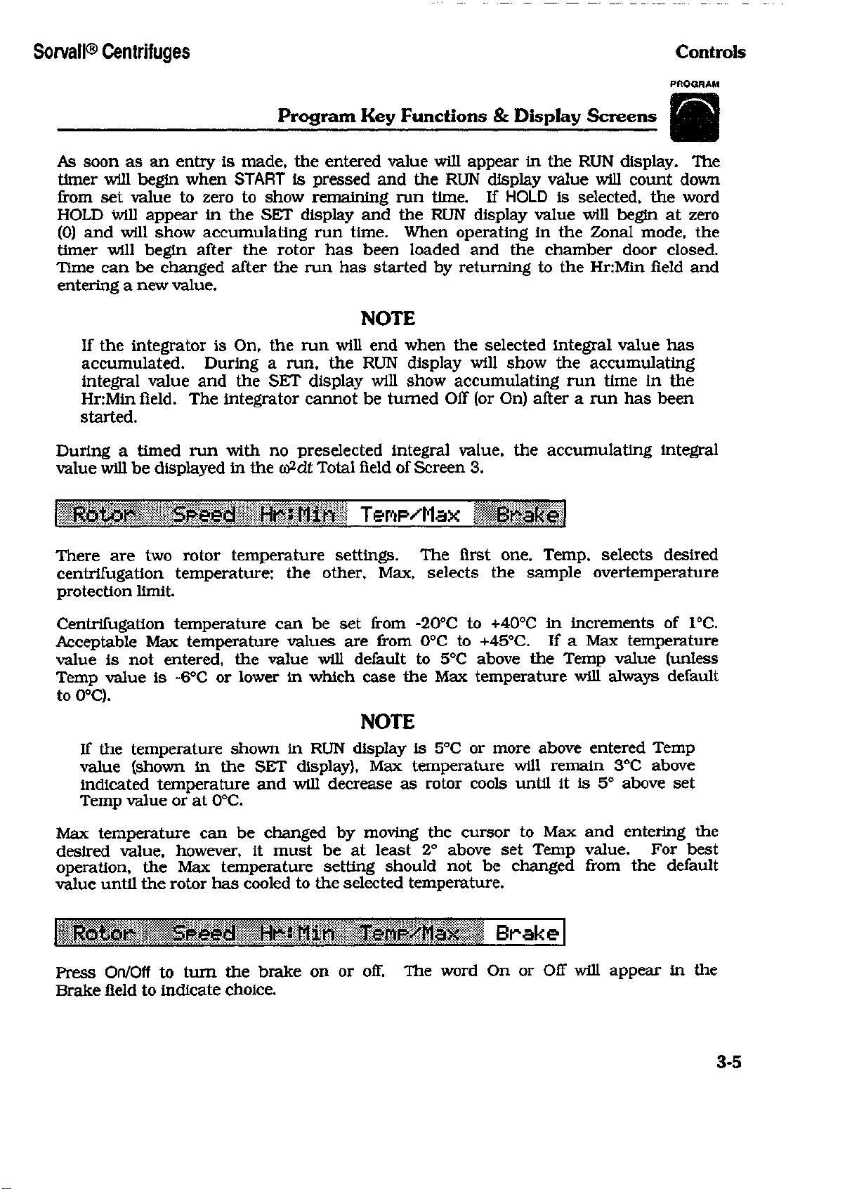
Press On/Off
Brake field
to
turn
the
to
indicate choice.
brake
on or off. The
word
On or Off
will appear
in the
3-5
Page 22
Controls Sorvall® Centrifuges
PROGRAM
Program Key Functions & Display Screens
When the brake is Off, the rotor will coast from set speed to zero rpm at the end of
the run. If a slow stop has been selected, the rotor will coast to the transition
speed, then continue to decelerate at the controlled rate. When the Brake is On,
the rotor will brake from set speed to zero rpm at the end of a run; if a slow stop
has also been selected, the rotor will brake to transition speed, then continue to
decelerate at the controlled rate.
C
o *> "CF
screen
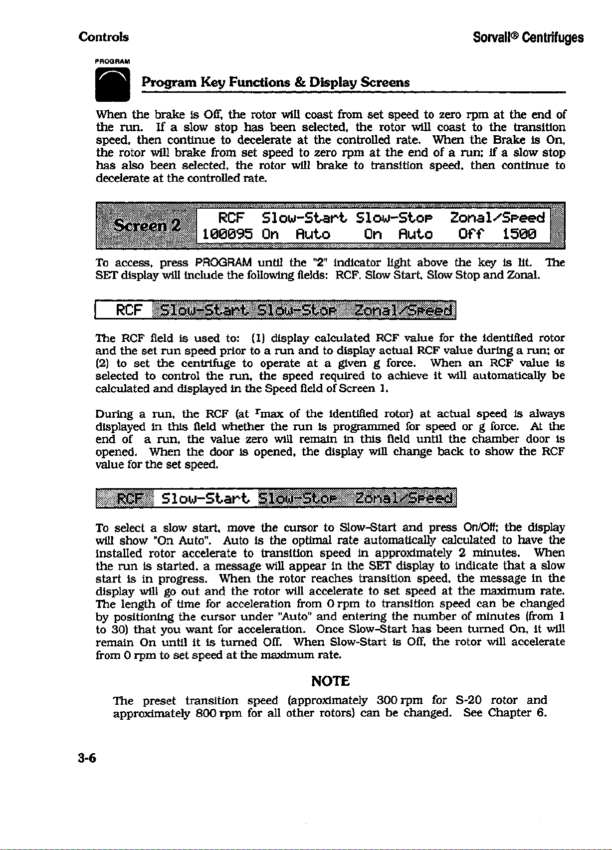
To access, press PROGRAM until the "2" indicator light above the key is lit. The
SET display will include the following fields: RCF, Slow Start, Slow Stop and Zonal.
RCF
z
100095 On fluto On fluio Off 1500
Slow-Start Slow-Stop Zonal/Speed
The RCF field is used to: (1) display calculated RCF value for the identified rotor
and the set run speed prior to a run and to display actual RCF value during a run; or
(2) to set the centrifuge to operate at a given g force. When an RCF value is
selected to control the run, the speed required to achieve it will automatically be
calculated and displayed in the Speed field of Screen 1.
During a run, the RCF (at rmax of the identified rotor) at actual speed is always
displayed in this field whether the run is programmed for speed or g force. At the
end of a run, the value zero will remain in this field until the chamber door is
opened. When the door is opened, the display will change back to show the RCF
value for the set speed.
RCF Slow-Start
To select a slow start, move the cursor to Slow-Start and press
will show "On Auto". Auto is the optimal rate automatically calculated to have the
installed rotor accelerate to transition speed in approximately 2 minutes. When
the run is started, a message will appear in the SET display to indicate that a slow
start is in progress. When the rotor reaches transition speed, the message in the
display will go out and the rotor will accelerate to set speed at the maximum rate.
The length of time for acceleration from 0 rpm to transition speed can be changed
by positioning the cursor under "Auto" and entering the number of minutes (from 1
to 30) that you want for acceleration. Once Slow-Start has been turned On, it will
remain On until it is turned Off. When Slow-Start is Off, the rotor will accelerate
from 0 rpm to set speed at the maximum rate.
On/Off;
the display
3-6
NOTE
The preset transition speed (approximately 300 rpm for S-20 rotor and
approximately 800 rpm for all other rotors) can be changed. See Chapter 6.
Page 23

Sorvall® Centrifuges Controls
PROGRAM
Program Key Functions & Display Screens
RCF Slow-Start Slow-Stop Zonal/Speed
To select a slow stop, move the cursor to Slow-Stop and press the On/Off key; the
display will show "On Auto". When On, the rotor will decelerate from set speed to
transition speed at the rate controlled by the brake setting. When the rotor
reaches transition speed, a message will appear in the SET display to indicate that
a slow stop has been initiated and the rotor will decelerate at a rate that will take it
approximately 3 minutes to reach 0 rpm. This rate of deceleration from transition
speed to 0 rpm is automatically calculated for the rotor in use. The rate of
deceleration can be changed by positioning the cursor under "Auto" and entering
the number of minutes (from 1 to 30) desired for deceleration. Once Slow-Stop
has been turned On, it will remain On until turned Off. When Slow-Stop is Off, the
rotor will decelerate at the rate controlled by the brake setting from set speed to
0 rpm.
NOTE
The preset transition speed (approximately 300 rpm for S-20 rotor and
approximately 800 rpm for all other rotors) can be changed. See Chapter 6.
RCF Slow-Start Slow-Stop Zonal/Speed
Used to select the Zonal mode of operation when dynamically loading a sample
and/or gradient into the Sorvall® TZ-28 Rotor. A Key# is required to activate the
Zonal mode.
When the Key# is entered and accepted, the word On appears in the display and
the cursor moves to Speed. Enter the Zonal loading speed from 1300 to 2500 rpm
(in increments of 10 rpm). When the chamber door is closed and START is
pressed, the rotor will accelerate to the Zonal speed, at which time the chamber
door can be opened and the sample/gradient loaded. After the sample and
gradient are loaded, close the chamber door and the rotor will accelerate to the
run speed selected in Screen 1 (the maximum Zonal run speed is 20 000 rpm).
At the end of the run, Zonal will turn Off automatically; therefore, each Zonal run
requires this option be turned On and the Key# entered.
Zonal cannot be stored in program memory; the zonal speed can be saved, but the
option must be turned On before the run.
w2dt Tine-out Total Lock
On
1.97e07
This screen includes w2dt and Lock. To access, press PROGRAM until the "3"
indicator light above the key is lit.
5.2QeQ7
On
3-7
Page 24

Controls Sorvall® Centrifuges
PROGRAM
Program Key Functions & Display Screens
w2dt Tine-out Total Lock
The Ja)2dt option
than a time value. Press On/Off
previous
deceleration,
(ENTER
Time-out value, first enter a three digit (X.XX) coefficient value
will automatically
the
During
and
accumulating value. During a timed
value
The integrator cannot
run
O) or
run.
an
integrator
the SET
and the
is
used
will automatically
and
Total
(START)
be
display will show selected Time-out integral value
Time-out value
to
program
to
be
is the
to
accept
placed), then
run, the RUN
be
turned
value
the
at the
On or Off
a run to end at a
turn
the |
displayed: Time-out
at 0 rpm,
Time-out value
a two
beginning
digit exponent value. Press (START)
display will show accumulating integral value
run, the SET
after
u2dt 1 on. The
which includes deceleration. Press
and
of
deceleration.
a run has
desired integral value rather
J(o2dt values from
is the
begin
display shows
the run. To
been started.
value
w2dt Tine-out Total Lock
This feature locks
changed until unlocked.
proper Key#. Once
in
the
Lock field
enter
the
Key#.
all set run
The
run
conditions have been locked
and in all
conditions (including options)
Lock
calculator screens.
is
activated
by
pressing On/Off
in, the
To
unlock, press On/Off again
cursor will only appear
at the
(the
decimal point
and the
the
accumulating
so
they cannot
and
start
change
to
begin
Total
entering
the
of
the
be
the
and
The lock cannot
~
A
screen
Run conditions
control centrifuge operation.
however, a program
be stored
Chapter
To access, press PROGRAM until
and a
6).
be
stored
in
program memory.
PROQRflM> Recall* Sauett
4
1
are
stored
can be
different Key#
in
program memory
A
Key# must
recalled without
can be
the "4"
PROGRFlM> Recall** Save*
Used
to
recall
the assigned program number (from
will automatically appear
run.
an
established program. Position
in
Screen
1 of the SET
^
and
be
entered
the
Key#. A total
assigned
indicator light above
1 to 20). The
to
the
display. Press START
recalled from memory
to
save
each program,
the key is lit.
cursor
recorded program parameters
in
a new
of 20
this field
programs
if
desired
to
program;
and
begin
to
can
(see
enter
the
3-8
Page 25

Sorvall® Centrifuges
Controls
PROGRAM
Program
Key
PROGRRM> Recall* Sauett
Used
to
save
all set
this field
Key#. When
and
enter a number from
the
assigned program number appears
that
was
the program.
which case,
input becomes
If
the
program numbers have been used, a new
program.
old program
In
this case,
is
automatically deleted from memory.
The CALCULATE
RCF,
speed,
below.
See
run
Chapter 5 for
run
conditions except Zonal
1 to
Key#
is
entered
and
in the
the
assigned program number that will
the
incorrect Key#
is
program number must
the
number assigned
Calculate
key
is
used
to
perform basic centrifugation calculations, including
time, Ju)2dt
and K Factor.
instructions
on
accepted,
entered,
be
Key
how
Functions & Display Screens
and
20. The
the
Save#
and
Lock. Position
display will prompt
display shows "Saved"
Recall# fields.
the
you
The
be
the
display will show
reentered, then
program
is
can
stored
for
the
be
stored over
the
new
"Not
correct Key#.
program
Functions & Display Screens
The
four calculator screens
to
use the
calculator.
used
Saved";
an
are
cursor
to
enter
and
in
the
number
to
recall
in
If
all
existing
and the
CALCULATE
pictured
1
2
3
4
CflLO
CRLO
CflLO
CRLO
Rotor
r(om)
Speed
Speed
Speed
K-Faciorl
Rrcax
Tinel
Diagnostics Key Functions & Display Screens
DIAGNOSTICS
is
used
to
monitor system operation, view system accumulators,
perform user diagnostic routines, install
calibrate replacement subassemblies.
screens
and
instructions
1
2
3
Fault
User-1
Maint-2
on
the use
Door- Sysien
User-2
Calib
of
See
this
new
key.
RCF
Tine w2dt
RCF
Rnin
K-Factor2
rotors
and
Chapter
Maint-1
Serv-1
K-Factor
Tine2
software, troubleshoot,
6 for
examples
Instal
of
1
Serv-2
DIAGNOSTICS
and
display
3-9/3-10
Page 26

Son/all® Centrifuges Operation
Chapter 4
OPERATION
This chapter provides:
• step-by-step operating instructions for the normal and zonal modes of
operation; RCF and
stop;
and HOLD runs;
• a description of the control panel lock and the Key# code;
• a precool/preheat procedure to equilibrate rotor and chamber temperature;
and
• a Rotor Information Chart.
Jco2dt
operation; programmed runs; slow start and slow-
Understanding the Centrifuge Controls
It is recommended that you read the description of the controls in Chapter 3
before using the centrifuge for the first time. You probably won't use all of the
controls right away, but reading Chapter 3 will give you information that will be
helpful in understanding the displays and how the control keys function, and it will
help you become familiar with all features of the centrifuge. As you use the
centrifuge, continue to refer to Chapter 3 whenever additional information is
needed.
Turning the Centrifuge On
The power ON/OFF switch is placed in the upper right hand corner of the front
cabinet panel. The microprocessor automatically runs a diagnostic test everytime
the centrifuge is turned on. If an error is found, a display message will appear in
the SET display on the control panel. If no error is found, the run parameters will
appear in the display indicating that the centrifuge is ready for operation.
Normal Run
A normal run is one that is controlled by time with selected run temperature and
run speed parameters and the brake set on or off. These parameters are selected
in the first screen of the (PROGRAM) key.
Prior to performing the run, prepare and install the rotor according to the
instructions in the rotor manual. To ensure that the sample, rotor, and chamber
temperatures are at equilibrium at the start of the run, follow the precool/preheat
procedure on page 4-12.
4-1
Page 27

Operation Sorvall® Centrifuges
WARNING
When loading the rotor, be sure not to exceed the maximum compartment
mass of the rotor (see Table 4-1, Rotor Information). If maximum compartment mass is exceeded, the maximum operating speed must be lowered
(see Reducing Speed for Rotor Compartment Loads In Excess of Design Mass,
page 4-12). Failure to do so can cause rotor failure which could result in
personal injury and/or centrifuge damage.
To perform the run:
1.
Turn the centrifuge power ON.
NOTE
For best run conditions and prolonged centrifuge life, the rotor chamber
should be dry at the start of a run. Before installing the rotor, wipe chamber
dry with a clean cloth or papertowel.
2.
Open chamber door all the way and install rotor. Close chamber door.
WARNING
Use Sorvall® rotors only. Use of another manufacturer's rotor can cause rotor
failure which could result in personal injury and/or centrifuge damage.
3.
The
"1"
light above the (PROGRAM) key should be on. If not, press (PROGRAM) until it is.
The name of the installed rotor will appear in the display and the cursor will be
positioned in the | Speed I field.
NOTE
If using an
to the 1 Rotor 1 field and input 18 for
rotor will be recognized as an S-20/36. Press (ENTER O).
4.
Input desired run parameters: | speed|, lHr:tiinl, and jTer>p/riax|. Press (ENTER E>) after
each input.
Max temperature will automatically default to 5°C above set run temperature; if
desired, enter a different value. For a continuous run, press (HOLD).
5.
Press (onoft) to make 1 Brake 1 selection. The word |0n| or [off | will appear in the
display to indicate selection made.
S-20/17
or
S-20/20
rotor ONLY: Press (ENTER <J) to move the cursor
S-20/17
or 17 for S-20/20; otherwise the
After you have selected the above parameters, the SET display should look similar
to the example below:
Rotor Speed HrsMin Tenp/Max Brake
F-28/13 28090
4-2
0:90
+4+9
On
Page 28

Sorvall® Centrifuges Operation
6. Select [siou-start] and/or [siou-SioH if desired (see below).
7.
Press (START).
Any of the run parameters, except rotor identification, can be changed while a run
is in process.
The rotor will accelerate to the set run speed and remain there for the selected
length of time then decelerate to a stop. To end a run in HOLD or before the
selected run time has elapsed, press (STOP).
NOTE
Integral value can be checked anytime during a timed run by pressing (PROGRAM)
until | u2dt | is in the display ("3" indicator light on). The accumulating fa)2dt
value will be in the | Total 1 field.
To do another run with the same parameters: prepare rotor and install it in the
centrifuge, then close chamber door and press (START) . All entered parameters
remain until a change is made.
Slow Start/Slow Stop
Slow Start and Slow Stop are used to prevent gradient disturbance during
acceleration and deceleration. When they are on, the rotor will accelerate or
decelerate to or from transition speed at a controlled rate that is slower than
normal (transition speed is preset at approximately 800 rpm for all rotors except
the S-20, which is preset at approximately 300 rpm; preset transition speed can be
changed, if desired - see Chapter 6). The length of time for the acceleration/
deceleration phase will automatically default to the optimal time for identified
rotor; or, if desired, time (from 1 to 30 minutes) can be entered manually.
NOTE
If Slow Start or Slow Stop are on, they will remain on for future runs until
turned off.
1.
Follow Steps 1 through 5 for a Normal run (page 4-2).
2.
Press (PROGRAM). The "2" indicator light above the key will light.
To select Slow Start:
1.
Press (ENTER O) to move cursor to |siou>-stari|.
2.
Press (on off).
3.
To accept the "Auto" time for acceleration and begin the run, press (START).
RCF blow-Start blow-Stop Zonal/Speed
100995
To change the length of time for acceleration from 0 to transition speed, press
(ENTER c>) to move cursor to | Ruto
30).
If a slow stop is desired (see page 4-5); if not, press (START) to begin the run.
On
fluto
Off Off 1509
I
and input desired number of minutes (from 1 to
4-3
Page 29

Operation
Use Sorvall® rotors only. Use of another manufacturer's rotor can cause rotor
failure which could result in personal injury and/or centrifuge damage.
Sorvall® Centrifuges
Table 4-1. Rotor Information
WARNING
ROTOR
SV-288
SV-80
GS-3
SA-600
SS-34
SE-12
HB-4
HS-4
SM-24
GSA
TZ-28
SH-MT
SH-80
CODE
#
1
2
3
4
5
6
7
8
9
10
11
12
13
MAX
SPEED
(rpm)
20 000
19.000
9000
16 500
20 000
21000
13 000
7000
20 000
13 000
20 000
13 730
20 000
CRITICAL
SPEED
(rpm)
1000
$
1600
1650
1200
1050
750
1200
1350
1700
1200
1000
1300
900
MAX
RCF
40 301
40 96$
13 689
39 411
47 807
45 959
27 579
9425
49 460
27 504
42 535
19140
45 394
FACTOR
4201
1678
4487
2
2019
s
K
210
97
792
750
513
457
605
656
399
COMPART-
MENT MASS
250.0 g
1035,0 0
2
680.0 g
1620.0 g
3
MAX
50.0 g
6.4 g
780.0 g
115,0$
115.0 g
30,0 $
27.0 g
36.4 g
78.0 g
r
MAX
(cm)
9.02
10.16
15.13
12.96
10.70
9.33
14.61
17.22
11.07
14J7
9.52
9.Q9
10.16
r
MIN
(cm)
6.47
8.84
3.93
5,52
3.26
3.81
4.75
7.21
2
5.37
2
3.77
3.65
3
5.57
5.40
3
F-28/13
F-28/36
3-20/36
S-20/20
S-20/17
SS-34/KSB-R
TZ-28/GK
1
With maximum allowable volume at maximum speed.
2
Outer row
3
Maximum speed of rotor is 20 000 rpm; actual maximum speed depends on tubes. Values given are typical for 1.5 ml microtubes.
14
15
16
17
18
19
20
28 000
28 000
20 000
20 000
20 000
20 000
19 000
1300
1300
400
400
400
1350
1000
100 09$
100 095
71934
58 083
7416S
47 807
38 38$
143
198
466
299
573
750
671
23,0 8
66.0 g
. 156.6 g
115.1 g
130.1 $
115.0g
1620.0g
11x43
11.43
16.10
13.00
16*60
10.70
9.52
4-4
7,34
6.18
7.70
8.10
6.70
3.26
3,65
Page 30

Sorvall® Centrifuges Operation
As soon as (START) is pressed, the |*** sioui start in Progress ***[ message will appear in
the SET display and will remain there until the rotor has accelerated to
approximately 20 rpm.
To select Slow Stop:
1.
Press (ENTER E>) to move cursor to [Sloui-stop].
2.
Press (on off).
3.
To accept the "Auto" rate of deceleration and begin the run, press (START).
RCF Slow-Start Slow-Stop Zonal/Speed
190095 On Ruto On Ruto Off 1500
To change the length of time for deceleration from transition speed to 0 rpm,
press (ENTER O) to move cursor to I nuto | and input desired number of minutes (from
1 to 30). To begin run, press (START).
During deceleration, the | *** siou stop in Progress *** [ message will appear in the
SET display as soon as the rotor reaches transition speed; the message will remain
in the display until the rotor stops spinning.
RCF Run
The centrifuge can be set to operate at a given g force rather than speed. When
you know the RCF (g force) you want applied to the particles during centrifugation,
you can use this feature to select the value. The run speed required for the set RCF
value will automatically be calculated.
To perform an RCF Run:
1.
Load and balance the rotor according to the instructions in the rotor manual. To
ensure that the rotor and chamber temperatures are at equilibrium, follow the
precool/preheat procedure on page 4-12.
WARNING
Use Sorvall® rotors only. Use of another manufacturer's rotor can cause rotor
failure which could result in personal injury and/or centrifuge damage.
Do not exceed maximum compartment mass of the rotor (see Table 4-1, Rotor
Information). If maximum compartment mass is exceeded, the maximum
operating speed must be lowered (see Reducing Speed for Rotor
Compartment Loads In Excess of Design Mass, page 4-12). Failure to do so
can cause rotor failure which could result in personal injury and/or centrifuge
damage.
2.
Turn the centrifuge power ON.
4-5
Page 31

Operation Sorvall® Centrifuges
NOTE
For best run conditions, the rotor chamber should be dry at the start of a run.
Before installing a rotor, wipe the chamber dry with a clean cloth or
papertowel.
3.
Open chamber door all the way and install rotor. Close chamber door.
4.
The
"1"
light above the (PROGRAM) key should be on. If not, press (PROGRAM) until it is.
NOTE
If using an S-20/17 or S-20/20 rotor ONLY: Press (ENTER O) to move the cursor
to the 1 Rotor 1 field and input 18 for an S-20/17 or 17 for an S-20/20; otherwise
the rotor will be recognized as an S-20/36. Press (ENTER O).
5. Input desired lHr:Minl and | Tenp/Max | values. Press (ENTER O) after each input. (Speed
is not entered because run speed will automatically be calculated and set when
the RCF value is entered.)
Max temperature will automatically default to 5°C above set run temperature; if
desired, enter a different value. For a continuous run, press (HOLD).
6. Press (on off) to make 1 Brake I selection. The word |0n | or joff | will appear in the
display to indicate selection made.
7. Press (PROGRAM) again.
I
RCF I will appear in the display with the cursor positioned in the I RCF 1 field and the
"2"
light above the (PROGRAM) key will be on.
8. Input desired |RCF| value (for rmax of the installed rotor). Press (ENTER O).
The display should look similar to the example below.
RCF Slow-Start Slow-Stop Zonal/Speed
93180 Off Off Off 1500
9. Press (START).
The rotor will accelerate to the speed required to achieve the set RCF value and
remain there for the selected length of time or until (STOP) is pressed, then
decelerate to a stop.
Key# Code
The Key# is a security number that must be entered in order to access Zonal,
Program Save, the control panel Lock, and some Diagnostic routines. Whenever
you attempt to use these features, the display will prompt you to enter the Key#.
4-6
Page 32

Sorvall® Centrifuges Operation
A different number can be assigned to each of the features that require a Key#,
including a different number for each of the 20 programs saved. There is also a
System Access Key# that allows access to any of the fields that require a Key#,
except for some Diagnostic routines. The centrifuge is shipped with the System
Access Key# 1234. This is the only number assigned when you receive the
centrifuge. For the procedures to change the System Access number or to assign
Key#s to the various features, see Chapter 6.
Zonal Run
Zonal operation allows you to operate the centrifuge with the door open at speeds
from 1300 rpm to 2500 rpm. This is used with a Sorvall® TZ-28 Zonal Rotor to
dynamically load gradient and sample. A Key# is required to access Zonal mode.
Assemble the rotor according to the procedure in the rotor instruction manual. To
ensure that rotor and chamber temperatures are at equilibrium at the start of the
run, follow the precool/preheat procedure on page 4-12.
To perform the run:
1.
Turn the centrifuge power ON.
2.
Open chamber door all the way and install rotor. Close chamber door.
3.
The
"1"
light above the (PROGRAM) key should be on. If not, press (PROGRAM) until it is.
4.
Input desired run parameters: I Speed I, |Hr:Minl and | Tenp/Max]. Press (ENTER O) after
each input.
NOTE
Maximum speed in the Zonal Mode is 20 000 rpm.
Max temperature will automatically default to 5°C above set run temperature; if
desired, enter a different value. For a continuous run, press (HOLD).
5.
Press (on off) to make | Brake I selection. The word
display to indicate selection made.
6. Press (PROGRAM) until the "2" light above the key is on and [ Zonal /Speed | appears in the
display.
[ On
| or |off [ will appear in the
NOTE
It is best to use a slow start and slow stop when doing gradient separations in
the TZ-28 Rotor (see Slow Start/Slow Stop, page 4-3).
7.
Select Isiou-start] and/or lsiou-stop] if desired.
8. Press (ENTER t>) to move the cursor to [ Zonal /Speed [. Press (on off). The display will
prompt you to enter | Ke^tt | (page 4-6).
9. Input | Ke^tt I and press (ENTER O). When the Key# has been accepted, the word
will appear in the display indicating that the centrifuge will operate in the Zonal
mode.
I On I
4-7
Page 33

Operation Sorvall® Centrifuges
10.
Input the desired loading speed (from 1300 rpm to 2500 rpm in increments
of 10). Press (ENTER D>).
At this point, the display should look similar to the following:
RCF Slow-Start Sloui-Stop Zonal/Speed
42535
When rotor reaches selected loading speed, the I*** Rotor at Zonal Speed> Load ***|
message will appear in the display indicating that the door can be opened.
When operating the centrifuge with the chamber door open and the rotor
spinning, remove any articles that could fall into the chamber (e.g., jewelry,
necktie, objects in shirt pockets). Tie back long hair and roll up shirt sleeves.
12.
Open chamber door and load the sample/gradient according to the instructions
in the rotor manual. When loading is complete, disconnect and remove any
equipment that was used to load it.
Off Off On 1500
WARNING
WARNING
When loading the sample and gradient, be sure not to exceed maximum
compartment mass specified for the rotor (see Table 4-1, Rotor Information).
If maximum compartment mass is exceeded, operating speed must be
lowered (see Reducing Speed for Rotor Compartment Loads In Excess of
Design Mass, page 4-12). Failure to do so can cause rotor failure which could
result in personal injury and/or centrifuge damage.
13.
Close the chamber door. The timer will begin and the rotor will accelerate to
the set run speed and remain there for the selected run time. At the end of the
run, the rotor will decelerate to 0 rpm and the Zonal function will turn off
automatically.
Hold Run
A Hold run is a run that will continue until (STOP) is pressed. All parameters except
time are entered as described for the type of run you will perform.
To select Hold:
Press (HOLD). Hold will appear in the iHrtliinl field of the SET display. While the
run is in process, the RUN display will show the accumulating time.
To end a HOLD run:
Press (STOP). The rotor will begin to decelerate and the run will end.
4-8
Page 34

Sorvall® Centrifuges Operation
To change a HOLD run to a timed run:
Press (HOLD). The key is a toggle switch so pressing it while in HOLD will return
the centrifuge to a timed condition. The last entered time value will appear in
the iHr:Hinl field of the SET display and the RUN display will show the
remaining time.
NOTE
When the centrifuge returns to a timed condition, the computer will account
for the length of time the centrifuge was in HOLD. Therefore, if the last
entered time value had already elapsed when the HOLD key was pressed again,
the RUN display will show zeros (0.00) and the rotor will begin to decelerate.
To enter a new time value and cancel the accumulated HOLD time:
Enter the new time value. The |Hr:Min| field of the SET display will show the
new set time, and the RUN display will change to countdown from the newly
entered value. The length of time the centrifuge was in HOLD has no affect on
the new set time.
fw2dt Run
An fa)2dt run allows you to set the centrifuge to end a run when a desired integral
value is reached.
To perform an fo>2dt run:
1.
Load and balance rotor according to instructions in the rotor manual. To
ensure that the rotor and chamber temperatures are at equilibrium, follow the
precool/preheat procedure on page 4-12.
WARNING
Use Sorvall® rotors only. Use of another manufacturer's rotor can cause
rotor failure which could result in personal injury and/or centrifuge damage.
Do not exceed maximum compartment mass of the rotor (see Table 4-1,
Rotor Information). If maximum compartment mass is exceeded, the
maximum operating speed must be lowered (see Reducing Speed for Rotor
Compartment Loads In Excess of Design Mass, page 4-12. Failure to do so can
cause rotor failure which could result in personal injury and/or centrifuge
damage.
2.
Turn the centrifuge power ON.
NOTE
For best run conditions, the rotor chamber should be dry at the start of a run.
Before installing a rotor, wipe the chamber dry with a clean cloth or
papertowel.
4-9
Page 35

Operation
3.
Open chamber door all the way and install rotor. Close chamber door.
4.
The
"1"
light above the (PROGRAM) key should be on. If it is not, press (PROGRAM) until
it is.
NOTE
Sorvall® Centrifuges
If usingan_S-20/17 or S-20/20 rotor ONLY: Press
to the [Rotor| field and input 18 for an S-20/17 or 17 for an S-20/20; otherwise
the rotor will be recognized as an S-20/36. Press (ENTERED).
5. Input desired I Speed! and press (ENTER >) twice to move the cursor to | Tenp/Max I.
(Time is not entered since the run will end when the integral value has
accumulated.)
6. Input desired 1 Tenp/Max 1 values. Press (ENTER PQ after each input.
7. Press (on off) to make [Brake! selection. The word [On] or | Off | will appear in the
display to indicate the selection made.
8. Press (PROGRAM) until the "3" light above the key is lit and |
display. The word [on] or [off] will appear in the | u2dt | field with the integral values
from the previous run displayed next to it. See example below.
CENTER<Q
to move the cursor
u>2dt I
appears in the
NOTE
Tine-out | is the
Total | is the fafdt value from the previous run at 0 rpm, which includes the
deceleration time.
J(o2dt
value from the previous run at the start of deceleration.
u2dt Tine-out Total Lock
On
1.94e07
5.29e07
Off
9. If Off, press (on off) to turn On.
10.
To use the |Tine-out) value, press (START). TO change the [ Tine-out 1 value, press
(ENTER
a two digit exponent value. Press (START).
The rotor will accelerate to the set speed and remain there until the integral value
has accumulated.
To end a run before the selected integral value has accumulated, press (STOP).
t>) and enter a new value: first a three digit (X.XX) coefficient value, then
Programmed Run
The RC-28S memory will store up to 20 programs. Each program saves a set of run
parameters that can be recalled by entering the assigned program number (from 1
to 20) and pressing (START).
4-10
Page 36

Sorvall® Centrifuges Operation
A Key# must be entered in order to store a new program or to make a change to an
existing program; however, a stored program can be recalled without the Key#. A
different Key# can be assigned to each program, if desired; see Chapter 6 for
procedure.
Program Save
1.
Enter all desired run parameters.
NOTE
Program Save will not store if the control panel Lock is on; also, Program
Save will not turn Zonal On.
2.
Press (PROGRAM) until the "4" indicator light above the key is lit.
3.
Press (ENTERO) to move the cursor to fsavettl and input a number from 1 to 20.
Press CENTER
4.
Input 1 Ke'd# | (page 4-6). Press (ENTER O) to store program. Press (START) to begin the
run.
PROGRflN > Reca11# Save#
1
1
5.
Record program number and run parameters in the Program Log Record
(located in back of the Operator's Guide under the centrifuge control panel).
NOTE
Program Recall will not turn Zonal On, but it will set loading speed and all
other parameters.
Program Recall
To recall a program:
1.
Press (PROGRAM) until the "4" indicator light above the key is lit.
2.
Input assigned program number (from 1 to 20). Press (START).
All prerecorded run parameters will automatically be established to control centri-
fuge operation. The displays will change to show the set run parameters for the
selected program.
Saved
Control Panel Lock
The control panel Lock will lock all set run conditions (including options) so they
cannot be changed until unlocked.
To lock or unlock set run conditions:
1.
Press (PROGRAM) until the
"3"
indicator light above the key is lit.
4-11
Page 37

Operation Sorvall® Centrifuges
2.
Press (ENTER oj to move the cursor to I Lock].
3.
Press (onoff) and input 1 Ke*#l (page 4-6). Press (ENTER O).
After run conditions have been locked in, the cursor will only appear in the [Lock
field and in all calculator screens.
Precool/Preheat
The following precool/preheat procedure is recommended to ensure that the rotor
and the chamber temperatures are at equilibrium at the start of a run.
1.
Open chamber door and install rotor. Close chamber door.
2.
Press (PROGRAM) until the
3.
Input I speed I of 2000 rpm. Press (ENTER O).
4.
Press (HOLD), then press (ENTER O).
5.
Input desired iTenpl. Press (ENTER O).
"1"
light above the key is lit.
6. Press (START) . The rotor/chamber should achieve temperature in approximately
30 minutes.
Reducing Speed for Rotor Compartment Loads
in Excess of Design Mass
There is a maximum allowable compartment mass established for each centrifuge
rotor (see Table 4-1, Rotor Information). To prevent rotor failure, the total
contents of any compartment, including specimen, tubes, covers, and adapters (if
used),
proportionately.
Strict adherence to the maximum allowable compartment mass or reduced speed
(see below) is required to prevent rotor failure. Observe WARNING on the Safety
Information Page in front of this manual.
The rotor speed is reduced in proportion to the square root of the ratio for the
maximum allowable compartment mass to the actual compartment mass (including
specimen, tubes, covers, and adapters). If the compartment mass is more than
that specified for the rotor, the reduced speed can be determined by using the
formula given below.
must not exceed the figure given in Table 4-1 unless rotor speed is reduced
4-12
„_,_,„
Reduced
^ ... „ « _, * I Maximum Compartment Mass
Rotor Speed = Max.mum Rotor Speed x \ Actual Compartment Mass (grams)
Page 38

Sorvall® Centrifuges
Calculator
Chapter 5
CALCULATOR
The RC-28S calculator allows you to perform basic centrifugation calculations to
help determine run conditions necessary to provide desired separation results.
Four screens of calculator functions are available. When you enter the CALCULATE
mode, the values displayed in Screens 1, 2 and 3 are calculated from the data
entered in the first three screens of the PROGRAM mode. To do calculations for a
different rotor, enter the rotor code number (see Table 4-1, Rotor Information) in
j
Rotor 1 field of CALCULATE Screen 1. The values displayed in Screen 4 (if any) are
from the previous calculation in that screen.
CALCULATOR DISPLAY SCREENS
2
3
4
1
CRLO
CflLO
CRLO
CflLO
Rotor
Ken)
Speed
Speed
Speed
Rroax
K-Factorl Tinel
RCF Tine
RCF
Rnin
K-Factor
K-Factor-2
w2dt
Tine2
liBIllillll CflLO Rotor Speed RCF Tine w2dt
Use to calculate SPEED, RCF (at rmax), TIME, and fo)2dt. To access, press
(CALCULATE) until the "1" indicator light above the key is on. Enter rotor code
number (see Rotor Information Chart) in the j Rotor 1 field.
To calculate SPEED from RCF:
1.
Position cursor in
2.
Press (ENTER O»). The calculated speed will be displayed.
To calculate RCF (at rmax) from SPEED:
1.
Position cursor in 1 Speed 1 field and input speed.
2.
Press (ENTER o). The calculated RCF value will be displayed.
|RCF 1 field and input RCF value.
To calculate estimated run TIME from
1.
Position cursor in | Speed 1 field and input speed.
2.
Press (ENTER t>) to move cursor to | u>2dt | and input Jafdt value.
3.
Press (ENTER O). The calculated run time will be displayed.
To calculate estimated
1.
Position cursor in | Speed [field and input speed.
2.
Press (ENTER O) to move cursor to [Tinel and input time.
3.
Press (ENTER t>). The estimated integral value will be displayed.
* It is not possible to exactly calculate Time from
approximate value to help you save time.
fa>2dt
from SPEED and TIME: *
j<o2dt
J<a2dt
or\w2dt from Time. These calculations are meant to give an
and SPEED: *
5-1
Page 39

Calculator Sorvall® Centrifuges
Calculator Use
Screen 2 ICflLO r(cn) Speed RCF
Use to calculate RCF or SPEED at a rotor radius other than the maximum. To
access, press (CALCULATE) until the "2" indicator light is on. The values in the
display are from Screen 1 of the (CALCULATE) key.
To calculate SPEED from RCF at a radius other than rmax:
1.
Position cursor in iKcrOl field and input radius.
2.
Press (ENTER O) to move cursor to |RCF 1 and input RCF.
3.
Press (ENTER P). The calculated speed will be displayed.
To calculate RCF from SPEED at a radius other than rmax:
1.
Position cursor in lr<cn)| field and input the radius.
2.
Press (ENTER O) and input [SpeedI.
3.
Press (ENTER P). The calculated RCF value will be displayed.
CRLO Speed Rmax Rnin K-Factor
Use to calculate K Factor. To access, press (CALCULATE) until the "3" indicator
light above the key is on. The values in the display are from
Screen 1 of the (CALCULATE) key.
To calculate K Factor at a particular speed using rmin and rmax diplayed:
1.
Position cursor in 1 Speed | field and input desired speed.
2.
Press (ENTER P). The calculated K Factor will be displayed.
To calculate K Factor using an rmin or rmax other than what is displayed:
1.
Verify speed and change if desired.
2.
Move cursor to | Rrcax | and/or [Rninl field and input radius value.
3.
Press (ENTER P). K Factor will be calculated and displayed.
Screen 4 CfiLO K-Factorl Tinel K-Factor-2 Tine2
Use primarily for pelleting runs to convert centrifugation time from one
rotor (Rotor-1) to another rotor (Rotor-2). To do so, you need to know the
K Factor at desired run speed for both rotors.
To calculate:
1.
Press (CALCULATE) until the "4" indicator light above the key is on.
2.
Input K Factor of
3.
Input run time from Rotor-1 in iTineil field. Press (ENTER P).
4.
Input K Factor of Rotor-2 in 1K-Factor2l field. Press (ENTER P). The run
time calculated for Rotor-2 will be displayed in jTine2| field.
Rotor-1.
Press (ENTER P).
* K Factor (the rotor clearing factor) is a function of sample path length (distance between rmin and rmax) and rotor speed. The
lower the K Factor value, the faster a given centrifugation protocol can be completed. Protocols can be converted from one
rotor to another if K Factors are known for both rotors.
5-2
Page 40

Sorvall® Centrifuges Troubleshooting
& Diagnostics
Chapter 6
TROUBLESHOOTING
and DIAGNOSTICS
This chapter provides:
• a description of SET display messages;
• DIAGNOSTICS information;
• the procedure to assign or change Key#'s; and
• the procedure to change the Slow Start/Slow Stop transition speed.
Display Messages
The RC-28S has a number of display messages that can appear in the SET display
on the control panel. These messages notify you of an operating condition or a
centrifuge fault that, in most cases, requires attention or demands action.
Following is a list of the SET display messages, along with the probable cause (in
bold print) and the corrective action.
***
Check Installed Rotor
The rotor management system did not recognize the installed rotor.
Possible causes are:
1.
the rotor management system was not properly activated;
2.
the installed rotor is not intended for use in the RC-28S;
3.
a rotor code was manually input that is incorrect for the installed rotor; or
4.
rotor/rotor lid not properly installed.
1.
To reactivate rotor management system, open the chamber door all the way and
close it again slowly.
2.
If the installed rotor is not meant for use in this centrifuge, remove it and install
one that is (see Table 4-1, Rotor Information).
Use Sorvall® rotors only. Use of another manufacturer's rotor can cause rotor
failure which could result in personal injury and/or centrifuge damage.
*#*
WARNING
3.
Install rotor to match selected rotor code; or, if the rotor you want is installed,
clear the message by opening and closing the chamber door. The rotor
management system will automatically recognize the installed rotor.
4.
Properly install rotor/rotor lid; refer to rotor instruction manual.
6-1
Page 41

Troubleshooting Sorvall® Centrifuges
& Diagnostics
*## Close Chanber Door
The chamber door
Close
the
chamber door
the door
Centrifuge malfunction.
Press (DIAGNOSTICS)
(page
all the way
***
Fault> Press DIRGNOSTICS ***
6-5) for
more information.
***
There
pressed.
Open
was no
the
chamber door
was not
first, then close
to
shut
Install Rotor
rotor installed when
***
completely closed when
all the way and
it.
off
alarm
press (START);
and
select DIAGNOSTIC mode.
***
the
chamber door
and
install a rotor. Close
the
the
(START)
it may be
was
door
and
key was
necessary
See
closed
press (START).
and
pressed.
to
open
Diagnostics
(START)
was
**# Open Chamber Door
Run
has
ended.
Open chamber door
***
Power Outage> Run Interrupted ***
A power outage occurred during
restored.
No corrective action required. Press (PROGRAM)
**# Pouer Outage> Run Terminated **#
A power outage occurred during
temperature significantly varied from
Restart
run.
and
remove rotor.
*##
the run. The run
the run. Run
set
parameters.
resumed when power
to
clear message.
terminated because speed and/or
was
6-2
Page 42

Sorvall® Centrifuges Troubleshooting
& Diagnostics
*** Recalled Rotor Hot Installed ***
A program was recalled that requires a rotor different than the one installed in the
chamber.
Install the correct rotor for the program recalled, or verify that you used the
correct program number.
*#*
Release Door Handle ***
Indicates that you tried to open the door before the door latch had released.
Release the door handle and wait until the message clears, then open the door. If
the problem does not clear, the door latch solenoid may be defective.
*#*
Replace NOURflM Battery Soon *#*
Battery for the centrifuge memory is low and must be replaced. (Average battery
life is from 5 to 10 years.)
Call for Service to replace battery.
#** Rotor at Zonal Speed> Load #*#
Zonal run is in process and rotor is at selected loading speed.
Open chamber door and load sample/gradient. Close chamber door.
*** Rotor Imbalance ***
Excessive rotor imbalance; run terminated.
Remove the rotor and balance it according to the instructions in the rotor manual,
then install rotor and restart the run.
*** Rotor Overtenperature *#*
Run terminated because display temperature is higher than selected 1 Max
temperature. Possible causes are: (1) selected 1 Max 1 temperature set below
displayed temperature; (2) rotor not precooled; (3) selected 1 Max [
low for the rotor/speed combination; (4) high ambient temperature; or (5)
condenser inlet blocked.
temperature too
1
Check possible causes: (1) if 1 Max 1 temperature was manually set lower than display
temperature, run will terminate when (START) is pressed; wait until actual
temperature cools to 1 Max 1 temperature setting and restart run or set a higher |
temperature and press (START) to restart run; (2) if rotor was not precooled, precool
Max
6-3
1
Page 43

Troubleshooting Sorvall® Centrifuges
& Diagnostics
it according to procedure on page 4-12; (3) acceptable rotor/speed/temperature
combinations vary depending on rotor used; in some cases, if temperature is set
lower than +2°C, rotor temperature may not be attainable at set speed; to achieve
temperature, set a lower speed; (4) check ambient temperature: it should be
between 15°C and 25°C for optimal performance; will operate at temperatures up to
38°C but performance will be less than optimal; (5) check for 6 inch clearance on
left side of centrifuge; clean condenser (to clean the condenser, see Chapter 7). If
problem does not clear, there may be a refrigeration system malfunction. See
DIAGNOSTICS.
*#*
Secure Rotor Properly
The rotor is not properly locked on the centrifuge drive.
Open the chamber door and tighten rotor locking knob(s); if the rotor has two
knobs, tighten the larger one first. Close chamber door and press (START).
***
Self Test
in
Progress
*#*
***
A diagnostic test of all centrifuge systems. This is done once every 24 hours that
the centrifuge power is ON.
No corrective action required.
##* Slow Start in Progress ***
Indicates that a Slow-Start was selected and initiated.
Message will clear automatically when rotor has accelerated to transition speed; no
corrective action.
*## Slow Stop
Indicates that a Slow-Stop was selected and initiated.
Message appears when the rotor has decelerated to transition speed. It will clear
as soon as the rotor has stopped spinning; no corrective action.
Tach Failure> Rotor Spinning
in
Progress
*#*
***
Tachometer has failed. Run is terminating, but the rotor is still spinning, even
though RUN display may indicate 0 rpm. The chamber door cannot be opened until
the rotor has come to a complete stop.
Wait until the
chamber door and remove the rotor. Call for Service.
6-4
I***
Open chamber Door ***[rnessage appears in the display, then open the
Page 44

Sorvall® Centrifuges
Troubleshooting
& Diagnostics
*** Tine
Twenty
Change vacuum pump
or
** Turn DIRGNOSTICS
The DIAGNOSTIC mode
to
Service Uacuun Punp
***
less vacuum runs remain before vacuum pump
oil as
Off
was
soon
as
possible (see Chapter
Before Start
exited with
one of
not start.
Press (DIAGNOSTICS) twice. Press (on
Press (PROGRAM)
***
Uacuun Punp Must Be Serviced ***
to
exit DIAGNOSTICS
off) to
and
turn
start
the
run.
Vacuum will not operate until vacuum pump oil
if set speed
is
higher than
the top
air speed*
of
rotor.
Change vacuum pump
oil
(see Chapter
7).
oil
must
be
changed.
7).
**
the fields turned on; centrifuge will
field
off.
Input
is
changed. Centrifuge will not start
the installed Sorvall® Supraspeed®
Q.
and
press (ENTER
O).
* Top
air
speed
is
equal
to
maximum speed
of
the rotor in an RC-5C Centrifuge. See rotor instruction manual.
Diagnostics
General
The DIAGNOSTIC information provided
understand
tasks that require
the
basics
of the
the use of
DIAGNOSTIC mode
DIAGNOSTICS. Common tasks done using
DIAGNOSTIC mode include assigning Key#s, changing
slow start/slow stop transition speed, identifying system faults,
shooting. Other routines
are
available
qualified service personnel only, therefore, instructions
included
best
The illustrations below
(Screen
to
in
this manual.
call
Du
4 is
currently
1
Pont
For
for
assistance.
are
not
Fault
1
of 2
information regarding
representative
used.)
Door Systerc
in
this manual
and to
in
DIAGNOSTICS that
use of the
of the
is
intended
teach
the
you to
vacuum pump
are
designed
for
their
service routines,
three DIAGNOSTIC screens.
to
help
you
perform routine
the
oil and the
and
trouble-
for use by
use are not
it is
2
3
User-l
Off
Maint-2
Off
User-2
Off
Calib
Off
Maint-l
Off
Serv-1
Off
Install
Off
Serv-2
Off
6-5
Page 45

Troubleshooting
& Diagnostics
Sorvall® Centrifuges
Following
Screen
Screen 1 identifies faults
1***
Fault> Press DIRGNQSTICS *** [ will appear
the cursor indicator lights beneath
alarm will sound every minute until (DIAGNOSTICS)
When (DIAGNOSTICS)
The fault information
System, Vacuum System); second, specific cause(s)
Failure, Vacuum Release Failure). As soon
fault description will appear
faults have occurred (e.g., Fault
two general faults occurred, the first being
Press (ENTER O). When you do, the fault information
a specific cause for the fault along with a string of binary numbers. Each" 1"
of binary numbers represents a separate cause for the fault. If there is more than one
press (ENTER
another cause
is an
1,
explanation of how to enter and move around
Faults
and
is
pressed, descriptive fault information will appear
is
arranged
Fault
1 of 2
O)
again and the cursor will move
for
the fault.
gives specific causes
the
display will move from left
in
two groups: first, general faults (e.g., Refrigeration
as
in the
1 of
Door System
display with
1, Fault 1 of 2, etc.). The example below shows that
in
in
the SET display, an alarm will beep, and
is
(DIAGNOSTICS)
an
the Door System.
to
the next" 1" and the display will show
in
the DIAGNOSTIC mode.
for
them. When a fault occurs,
pressed and the fault
for the
indication
in
the display will change
fault (e.g., Compressor
is
pressed, the first general
of
how many general
to
right.
is
cleared.
in the
in
display.
to
the string
The
show
"1",
Continue
returned
Fault
1 of
change
to
Fault
1
of 2
to
press (ENTER
to the
show the next general fault;
|Fault| field.
3), when the cursor returns
Door
O)
If
Not
until
there was more than one general fault (i.e., Fault
Locked
all
causes have been displayed
to
the Fault field,
for
example:
Fault Uacuun Systen
2
of 2
Continue
screen again includes the first general fault (e.g., Fault
As
displayed; this information will
troubleshoot the problem.
After
|»»*
not clear when (STOP)
to clear
faults were displayed.
to
press (ENTER
O)
until
all
faults have been displayed
NOTE
you
move through
all
faults have been identified
Fault > Press DlRGNOSTics ***| message from the display.
the
message. Call
the
fault screens,
is
pressed, turn
for
be
sure
be
required
and
Service; when you call,
written down, press
the
centrifuge power OFF then back ON
and
the
display will automatically
and the
1 of
2, Door System).
to
make a note
to
help Service personnel
If
let
Service know which
of
each fault
the message does
cursor
SET display
has
1 of 2,
clear
6-6
Page 46

Sorvall® Centrifuges
Troubleshooting
& Diagnostics
Screen
Screen
perform some maintenance routines, such
2
2 is
used
to
monitor system operation; install
as
assigning Key#'s (procedure
new
changing slow start/slow stop transition speed (procedure
the vacuum pump
Table
6-1
describes what each field
to access
the
field.
oil
(page
Table
7-4).
6-1.
is
used
for and
what authorization (Key#)
Screen 2 Fields, DIAGNOSTICS
Field Purpose
Screen
User-1
2
To
User-1 User-2
monitor state
such
as
vacuum level
of
system operation,
and air
Maint-1 Install
temperature.
User-2
To
such
vacuum
perform user diagnostic routines,
as
entering Key#s
and
changing
oil.
software;
on
add new
page 6-12),
rotors;
on
and
is
page
changing
required
Authorization Required
None
System Key#
and
6-9),
Maint-1
Instal 1 To
To enter Screen
Position
necessary, then enter
operation (Table
To
the
cursor under
view system accumulators.
install software
2,
press (DIAGNOSTICS) until
the
the
6-2) and
press (ENTER
To exit DIAGNOSTICS, press
and press (ENTER
Selection
USER-1
#
1
2
3
4
5
6
7
8
9
10
11
12
13
14
15
O-).
Table
Vacuum Level (mbar)
Ctrlr Samp Temp
6-2.
Operation
Samp Temp Offset
Air Temp
Base Temp
Jumper Temp
Winding Temp
(deg
(deg
C)
(deg
(deg
Measured Rotor Inertia
Door Home Microswitch
Door X Position
Door Closed Switch
Door Lock Sensor
URRID lst/2nd
URR Y Value
Motor Direction
None
field
and add new
the "2"
you
want
to use and
rotors.
System Key#
indicator light above
press
(on off).
selection number that corresponds
O).
Press
to turn selection
DIAGNOSTICS, Screen
(deg
C)
(deg
C)
C)
C)
C)
(on off) to
Selection
USER-1
turn selection
off,
enter selection number
2,
Operations
#
Operation
(continued)
16
Tachometer Frequency-
17
Slow Transition Speed
18
Vacuum Transition Speed
19
Imbalance Threshold
20
Drive Relay-
21
Rail Enable
22
Rail Setting
23
Rail Volt Sense
24
Brake Enable
Brake Setting
25
26
Drive Enable (Ctrlr)
27
Drive Enable (Host)
28
Bridge Enabled (Yes/No)
29
Bridge Chop (Half/Full)
30
Bridge Setting (Amps)
the key is lit.
Enter Key#,
to the
on.
(V)
(%)
if
desired
0
continued
—
6-7
Page 47

Troubleshooting
& Diagnostics
Sorvair Centrifuges
Selection
USER-1
USER-2
Table
#
6-2.
DIAGNOSTICS,
Operation
(continued)
31
Bridge Current Sense
32
HES Offset
33
Host State
34
NovRAM
35
NovRAM
36
Min
37
Max
38
Raw
39
Min
40
Max
41
Raw Base Temp
42
Max Base Temp
43
Raw Jumper Temp
44
Min Jumper Temp
45
Max Jumper Temp
46
Raw Winding Temp
47
Max Winding Temp
1
System Access Key#
2
Zonal Access Key#
3
Lock Access Key#
4
Program (1-20) Key#
5
Slow Transition Speed
6
Press
7
LCID Display Test
8
Vacuum System Override
9
Remote Baud Rate
10
Clear Faults
(U2)
(U4)
Vac
Level (mbar)
Vac
Level (mbar)
Air
Temp
Air
Temp
Air
Temp
On
for
Oil
Battery
Battery
(deg C)
(deg C)
(deg C)
(deg C)
(deg C)
(deg
(deg C)
(deg C)
(deg C)
(deg C)
Change
(A)
OK?
OK?
C)
Screen
Selection
MAINT-1
INSTALL
2,
Operations (continued)
#
1
Serial Number (Year)
2
Serial Number (Unit)
3
Hours
4
Hours
5
Number
6
Hours
7
Hours Since
8
Number
9
Cycles Since
10
Drive Revs
11
w2dt (mantissa)
12
w2dt (exponent)
13
Number
14
Successful
15
No Match
16
Failed
17
Loose
18
Mismatched
19
Runs Ending with Faults
20
Last General Faults
21
Prior General Faults
22
Controller ROM Version
23
Host
24
Host ROM
1
Install Rotor
2
Install NovRAM
3
Install ROM
Operation
of
System
on
Drive
of
Drive Cycles
on
Vacuum Pump
Oil
of
Vacuum Cycles
Oil
(*10A6)
of
URR Cycles
URR
URR
URR
Cycles
Lid URR
URR
ROM (U5)
(U8)
(U5)
on
Time
Change
Change
on
Drive
on
Drive
Cycles
Cycles
Cycles
Cycles
Version
Version
6-8
Screen
Screen
lists
the
for
use by
Field Purpose
Screen
Maint-2
Calib
Seru-1
Serv-2
3
3 is
used
fields
DuPont
3
To
To
To
To
for
in
calibration
Screen
Table
3 and
or
other Service Personnel only.
6-3.
and
advanced troubleshooting
describes their purpose.
All of
and
the fields
Screen 3 Fields, DIAGNOSTICS
Authorization Required
Maint-2 Calib Seru-2
access diagnostic routines available
DuPont personnel only.
calibrate replacement subassemblies.
monitor system status
for
advanced
troubleshooting.
access diagnostic routines
advanced troubleshooting
and
for
repair.
to
repair. Table
in
this screen
No access
Service Personnel
Service Personnel
Service Personnel
6-3
are
Page 48

Sorvall® Centrifuges
Troubleshooting
& Diagnostics
How to Assign or Change a Key#
The centrifuge is shipped with a factory-set System Access Key# of "1234" that will
allow access to most fields that require a Key# (Screen 3 Service Diagnostics cannot
be accessed by the System Access Key#).
If desired, you can change the System Access Key# and you can set different Key#s
for various features, such as: the control panel Lock, Zonal, and up to twenty
different Program Save Key#s. All Key#s must consist of four digits or less.
NOTE
Record all Key#s and keep them in a place where they will not be lost. If
Key#s are lost, call Du Pont for assistance.
System Access Key#
To change the System Access Key#:
1.
Press (DIAGNOSTICS) until the "2" indicator light above the key is on and the display
looks as follows:
User-1 User-2 Maint-1 Install
Off Off Off Off
2.
Press (ENTER O) to move the cursor to 1 User-2
3.
Press (on off). The display will prompt you to enter a Key#:
User-1 User-2 Maint-1 Install
Off Key# Off Off
4.
Input current |s-=isterc Recess Ke*#1 and press (ENTER O) ; display will look as follows:
User-2 <Ouride> Press Q or On to Exit
9 Off
5.
Input 1 in the 1 User-21 field and press (ENTER O); cursor moves to |<Ovride)l.
User-2 (Quride) Systen Recess Key#
1 Off 1234-
CURRENT
ACCESS
KEY#
SYSTEM
6. Press (onoff) to turn | <ovride)[ on, then press (ENTERE»»).
7.
Input the new | systen Recess Ke^#| (four digits or less). Press (ENTER D>).
User-2 <Ovride> Systen Recess Key#
1 On
8. Press (on off) to turn l«3vride)| off and press (ENTER O).
4444-
EXAMPLE
NEW
SYSTEM
ACCESS
OF
KEY#
6-9
Page 49

Troubleshooting
& Diagnostics
Sor vail® Centrifuges
9. Record
the
new System Access Key#.
To change other Key#s (i.e., Zonal, Lock,
appropriate procedure that follows;
System Access Key# procedure.
If
you are not
performing steps
10.
Input
Q.
in 1 User-21 field
going
10 &
to
assign
11 below.
and
or
press (ENTER D=>). The display will change back
User-1 User-2 Maint-1 Install
Off
Off Off Off
11.
Press
Zonal and Lock Access Key#s
Follow Steps 1 through
(PROGRAM)
to
exit
DIAGNOSTICS.
4 of
System Access Key# procedure, then:
NOTE
or
Program),
do not
repeat Steps 1 through
change other Key#s, exit DIAGNOSTICS
go to
Step
1 of the
4 of the
to:
by
1.
To
change
Key# input
2.
Press (ENTER
3.
Press (on off)
4.
Press (ENTER
5.
Press (on off)
6. Press (ENTER
the
Zonal Key#, input
2 in the
| User-21 field. The display will change:
2 in the I user-21 field:
User-2 CQuride) Zonal Recess Key#
2
Off 1234
or
User—2 (Ouride) Lock
3 Off
O); the
to
O) and
cursor will move
turn kovride)
input
the
to
|<ovride>l.
on.
new Key# (four digits
or
less). Press (ENTER
User-2 <0vride) Lock Recess Key#
3
On
to
turn kovride)!
>) to
move cursor
2222
off.
to 1 User-21 field.
or to
change
O).
the
CURRENT
ACCESS
KEY#"S
EXAMPLE
NEW
LOCK KEY#
Lock
OF
6-10
Page 50

Sorvall® Centrifuges
NOTE
To assign or change Program Key#s, go to Step 1 of the following procedure,
but do not repeat Steps 1 through 4 of the System Access Key# procedure. If
you are not going to assign Program Key#s, do steps 7 and 8 to exit
DIAGNOSTICS.
7.
Input £ in 1 User-21 and press (ENTER O). The display will change back to:
Troubleshooting
& Diagnostics
8.
Press
(PROGRAM)
User-1
Off
to
exit
User-2
Off
DIAGNOSTICS.
Maint-1
Off
Install
Off
9. Record new Key#.
Program Key#(s)
A Key# is required to save a program and to make changes to an existing program,
but it is not required to recall a program.
A different Key# can be assigned to each of the 20 possible programs, if desired.
Follow Steps 1 through 4 of the System Access Key# procedure, then:
1.
Input 4 in the 1 User-21 field and press (ENTER O).
User-2 < Task
Pro9ran<l-20) Key#
4 Off
2.
Press (on off) to turn |< Task >1 on; display changes:
User-2 ( Task ) Enter Program Nunber
4 On 9
3.
Press (ENTER
again.
User-2 < Task
4.
Press (ENTER O) and input the Key# (four digits or less) that you want assigned to
the program (Program #01 is in the example above and below).
User-2 < Task > Key# for Progran #91
5.
Press (ENTER o); cursor moves to |< Task )[. Press (on off) to turn [< Task )| off.
To assign or change Key#s for other Programs, repeat steps 2 through 5.
and input the desired program number (1-20). Press (ENTER O)
Key# for Pro9ran #91
4 On
1234
4 On 3333
CURRENT
FOR
PROGRAM 1
EXAMPLE
NEW
KEY# FOR
PROGRAM
NOTE
KEY#
OF
1
6-11
Page 51

Troubleshooting
Sorvall® Centrifuges
& Diagnostics
6. Press (ENTER O) to move cursor to | User-21 field. Input Q, and press (ENTER O). The
display will change back to:
User-1
Off
7.
Press
8. Record new Key#s.
(PROGRAM) to
exit
User-2
Off
DIAGNOSTICS.
Maint-1
Off
Install
Off
How to Change Slow Start/Slow Stop Transition Speed
The slow start/slow stop transition speed is approximately 800 rpm for all rotors except
the S-20 rotor, which has a transition speed of approximately 300 rpm; and the GS-3
rotor, which has a transition speed of approximately 650 rpm.
Transition speed can be changed to any speed from 100 rpm to 1000 rpm (the selected
speed will be rounded to the nearest number that is divisible by 4). When the transition
speed is changed, it will affect the next run only (unless stored in a program); at the end
of the run, it will automatically change back to the default speed of 800 rpm (300 rpm
for the S-20 or 650 rpm for the GS-3). Anytime you want a run with a transition speed
other than the default speed, you must change it prior to the run or store the transition
speed as part of a saved program.
Prepare and install the rotor according to the instructions in the rotor manual. Close
chamber door and select other desired run parameters, then change transition speed:
1.
Press (DIAGNOSTICS) until the "2" indicator light above the key is on and the display
looks as follows:
User-1
Off
2.
Press (ENTER O) to move the cursor to |user-2|.
3.
Press (on off) The display will prompt you to enter a lKe*# |.
4.
Input the Is^sten Recess Ke*#| and press (ENTER O).
User-2
Off
User-2 <0uride) Press
Q
Off
5. Input §. in the [user-21 field and press (ENTER
Maint-1
Off
Q or On to
Install
Off
Exit
User-2 <0uride) Slow Transition Speed
5 Off 8Q0
6. Press (on off) to turn l«x»ride)l on, then press (ENTER
I
Slow
Transition
Speed
I.
to move cursor to
6-12
Page 52

Sorvall® Centrifuges Troubleshooting
& Diagnostics
7.
Input desired transition speed (from 100 rpm to 1000 rpm).
CAUTION
Do not set transition speed at the critical speed (±100 rpm) of the rotor (see
Table 4-1, Rotor Information, for critical speed). Slow start in the critical
speed range can have a detrimental effect on centrifuge components.
8. Press (ENTER O) ; when you do, the cursor will move to 1 <0vride)|. Press (on off) to turn
kOvride)! off.
9. Press (ENTER O) and the cursor will move to
10.
Input Q in|user-2land press (ENTER I>). The display will change back to:
|Us.er-21.
User-1 User-2 Maint-1 Install
Off
Off Off Off
11.
Press
12.
Press
(PROGRAM)
(START)
to exit DIAGNOSTICS.
to begin run.
NOTE
If the chamber door is opened after the transition speed has been changed,
the transition speed will automatically change back to the default speed.
6-13/6-14
Page 53

Sorvall® Centrifuges
Maintenance
Chapter 7
MAINTENANCE
This chapter describes routine maintenance procedures that are to be performed by the
user. Any further maintenance should be performed by a DuPont Service
Representative or other qualified service personnel.
WARNING
Because the high voltage electrical circuits in this centrifuge can cause severe
electrical shock, untrained personnel must not attempt procedures that are
not included in this manual. Failure to comply with this warning can result in
personal injury.
If hazardous materials have been processed in the centrifuge, take all
necessary precautions when cleaning or servicing the centrifuge to avoid
personal exposure to contaminants.
To gain the most in safety, performance, and useful life from your centrifuge, it is
necessary to maintain it as described in this chapter. Proper maintenance is a simple
and inexpensive way to help prevent major failures. In addition to the maintenance
described in this chapter, a Du Pont service contract, which includes a yearly
Preventive Maintenance visit, is recommended to keep your centrifuge in top condition.
The following is a suggested maintenance schedule.
Table 7-1. Maintenance Schedule
Maintenance
Clean the rotor chamber
Wash the tapered spindle
Clean cabinet panels
Clean the control panel
Clean condenser coils
Clean air inlet louvers
Clean and inspect door seal
Daily or immediately after a spill
Once a week
Once a month
Once a month
Check monthly; clean as required
Check monthly; clean as required
Once a month or whenever vacuum
performance is poor
Frequency
Change vacuum pump oil and
mist eliminator filter
Test RUN display lights
and control panel indicators
Once a year or when the message
|+**
Tine to Service Uacuuri Punp ***|
appears in the SET display.
Once a year or whenever numbers
displayed seem erroneous.
7-1
Page 54

Maintenance Sorvall® Centrifuges
Cleaning
Rotor Chamber
The rotor chamber should be kept clean and wiped dry routinely to maintain
efficient cooling. Wash the chamber with a mild dishwashing liquid, then rinse and
dry with a soft absorbent cloth.
Use 70% ethanol to disinfect the rotor chamber or a 2% glutaraldehyde solution to
sterilize it. For general radioactive decontamination, use a solution of equal parts of
ethanol, 10% SDS, and water. Follow this with ethanol rinses then deionized water
rinses.
radioactive waste containers.
Tapered Drive Spindle
Wipe the drive spindle with a soft cloth each time a rotor is to be installed to
reduce the chance of the rotor sticking. Once a week, wash the drive spindle with
warm water.
Dry with a soft absorbent cloth. Dispose of all wash solutions in proper
CAUTION
Chlorides are extremely harmful to aluminum alloy rotors and can cause stress
corrosion cracking. Therefore, do not use chlorides to disinfect the chamber.
Cabinet
Clean the Noryl® cabinet panels with a household wax cleaner. Use a mild
noncdkaline
detergent and water to clean the top deck and the chamber door.
Control Panel
To clean the control panel, spray a small amount of a mild cleaning liquid (such as
window cleaner) on a clean cloth and wipe the panel clean. DO NOT spray cleaners
directly on the control panel.
Door Seal
The chamber door seal should be cleaned once a month. If the seal is not kept
clean, it can result in an insufficient vacuum level during a vacuum run.
To clean the seal:
1.
Open the chamber door all the way. Using a #1 phillips (or Reed-Prince)
screwdriver, loosen the quarter-turn fastener (turn counterclockwise) on the
front edge of the door (figure 7-1, view 1).
2.
Close the chamber door halfway, then locate the hole in the center of the tray
assembly, underneath the door (figure 7-1, view 2). Insert your fingers approximately 13mm (1/2 inch) into the hole and pull forward on the silver seal tray
until the hole is visible. Continue pulling tray out while pushing back on the door
handle until the door is fully open and the seal tray assembly is separated from
the door. Remove the sealing assembly.
7-2
Page 55

Sorvall® Centrifuges
3.
Inspect the top and bottom perimeter of the seal for signs of cracks, tears, or
abrasions. If damaged, replace the door seal assembly, Catalog No. 59235.
4.
Wash the centrifuge deck and both sides of the door seal and tray with a mild
noncdkaline laboratory detergent and rinse well.
5.
With the door fully open, carefully engage both corners of the tray in the door
tracks, then slide the seal tray assembly back into the door. Secure it in place
with the quarter-turn fastener.
Do not operate the centrifuge without the seal tray assembly in place. The
assembly is part of the centrifuge containment system, which provides
protection in the event of a rotor failure.
1.
Maintenance
WARNING
3.
Figure 7-1. Door Seal Removal
7-3
Page 56

Maintenance Sorvall® Centrifuges
Refrigeration System Condenser
To maintain the efficiency of the refrigeration system, keep the condenser fins (located
on the left side of the centrifuge) free of dust and dirt. Clean the fins with a brush or
vacuum cleaner at one to three month intervals. The fins will bend easily; be very
careful when cleaning them.
Air Louvers
To allow proper air flow through the centrifuge, the air louvers on the front cabinet
panel should be kept free of dust and dirt. Clean the louvers with a brush or a vacuum
cleaner as needed.
Lubrication
All components are prelubricated and require no further lubrication. The refrigeration
unit is hermetically sealed and the ball bearings in the centrifuge motor are
permanently lubricated.
Vacuum pump oil must be changed whenever the | »** Tirte to Service Uacuurc
message appears in the SET display or once a year, whichever occurs first.
Pump
*** |
Changing the Vacuum Pump Oil & Mist Eliminator Filter
The most common cause of vacuum pump failure or poor performance is contaminated
oil.
To ensure the efficiency of the vacuum system operation, the vacuum pump oil
must be changed whenever the 1 *** Tine to Service Uacuurc Punt* ***! message appears
in the SET display or once a year, whichever occurs first.
The | *** Tine to Service Uacuurc Punp *** 1 message will appear in the SET display on
the control panel to warn you that twenty or less vacuum runs* remain before the
vacuum will not operate. The oil should be changed as soon as possible after this
message appears. If the oil is not changed before the twenty vacuum runs are up, the
{*** Uacuun Furcp Must Be Serviced »»*! message will appear in the display when you
attempt to start the twenty-first vacuum run and an interlock will prevent further
vacuum operation until the oil is changed.
A DuPont Oil Change Kit, Catalog No. 12870, is required for this procedure. The kit
includes the items needed to change the oil: a bottle of vacuum pump oil, a mist
eliminator filter, a plastic exhaust port blocking tube, a piece of tape, and a funnel.
NOTE
If you are not using the DuPont Oil Change Kit, you must use oil that
meets the same specifications as the oil supplied in the kit. The
specifications for the oil are given in the Appendix of this manual with a
list of additional items required.
* A vacuum run occurs when a Sorvall9 Si/praspeed® rotor is operated above its maximum air speed. Maximum air speed is equal
to maximum speed of the rotor in an RC-5C Centrifuge. See rotor instruction manual.
7-4
Page 57

Sorvall® Centrifuges Maintenance
Refer
to
Figure
7-2 for
parts location
and
change
the
vacuum pump
oil:
NOTE
It
is
best
to
change
warm
1.
Turn
2.
Peel
over
3.
Turn
of panel
4.
Remove right access panel from behind control console
panel
and
will pump
the
centrifuge power
the
back
off the
the
left-hand inlet port
the two
and
fasteners
out,
then down,
lifting
up.
the oil
out
while
easier.
ON and
piece
of
tape supplied
to
completely seal
at
the
bottom
and
remove panel from centrifuge.
If
necessary, strike
it is
open
of
warm, since
the
chamber door.
in
the Oil
the
the
lower front cabinet panel. Pull bottom
end
of
it is
less viscous when
Change
port.
by
panel lightly
Kit,
then stick
pressing
to
pop
in on
panel
off.
the
tape
end
of
WARNING
Leave chamber door open while access panel
avoid
the
and
possibility
the
door track behind
of
pinching your hand
the
console.
is
off.
This
and
fingers between
is
necessary
the
to
door
5.
Loosen knob
6. Remove mist eliminator filter
7.
Install
the
eliminator. Reinstall
full turns after
8. Remove entire length
on
cap
of
mist eliminator. Then, remove
and
screen. Discard filter
exhaust port blocking tube (supplied
the cap and
you
first feel resistance.
of
vacuum pump drain line from channel
knob assembly
in
and
the kit)
panel.
9. Remove drain line tubing clamp, then securely position
bottle having a capacity
of
one
liter
or
more.
NOTE
10.
Make sure
the access panel
Turn
the
a.
Press (DIAGNOSTICS) until
appears
the
drain line tubing
and
vacuum pump
in
the
display.
User-1
Off
where
on:
the
User-2
is
not
kinked, particularly near
it
was
crushed
"2"
indicator light above
Maint-1
Off
by
Off
the
tube clamp.
cap and
and
on
tighten
end
of
the key
Install
Off
knob assembly.
keep
the
screen.
the
stem
of
it:
turn
the
in
front access
drain line
in a waste
the top
is on
and 1 User-2
the
knob
of
mist
two
b.
Press
prompt
(ENTER
you
User-1
E>)
to
Off
to
enter
move
the
a Key#:
User-2
Key#
cursor
to User-2
Maint-1
Off
.
Press (on off);
Install
th
Off
7-5
Page 58

Maintenance
Sorvall® Centrifuges
LEFT-HAND
INLET PORT
KNOB-
MIST
ELIMINATOR
CAP
MIST
ELIMINATOR
SCREEN
EXHAUST
PORT
BLOCKING
TUBE
MIST
ELIMINATOR
FILTER
STEM
OF
MIST
ELIMINATOR
RIGHT
ACCESS
PANEL
QUARTER-TURN
FASTENERS
7-6
FRONT
PANEL
Figure
7-2. Oil
DRAIN LINE
TUBING CLAMP
DRAIN
LINE
CLAMP
IN
PLACE
Change Parts Identification
RIGHT SIDE
INLET PORT
PLUG
ONE
LITER
WASTE
BOTTLE
CLAMP REMOVED
Page 59

Sorvall® Centrifuges
c. Input the System Access Key# and press (ENTER D>).
User-2 (Quride) Press 9 or On to Exit
d. Input £ and press (ENTER O).
User-2 < Task ) Press On for Oil Change
e. Press (on off) and press (ENTER O).
Usei—2 < Task ) Enter 1 to Run PUNP
f. Input 1 and press (ENTER O).
User-2 < Task ) Enter Q Nhen Enpty
Maintenance
9 Off
6 Off
6 On 9
6 On
NOTE
If vacuum pump turns off within 30 seconds after it is first turned on,
check to make sure the piece of tape inside chamber completely seals inlet
port and that the inlet port plug on left side of centrifuge is firmly in place.
11.
Run the pump until air comes through the drain line and froth begins to appear in
the waste container; this indicates that the pump is empty. Immediately press
(ENTER O) , input Q. and press (ENTER O) again to turn pump OFF and avoid
damaging the pump.
CAUTION
Do not run the pump after it is empty. To do so can damage the pump.
NOTE
The pump will turn off automatically after 4 minutes. If the pump is not
empty after the 4 minutes, press (ENTER O), input 1 and press (ENTER E>)
again to continue running the pump.
12.
Press (onoff) to turn |< Task )| off.
13.
Press (ENTER O) to move the cursor under | User-21 • Input 0 and press (ENTER O») .
14.
Press (PROGRAM) to exit DIAGNOSTICS.
15.
Wipe oil from drain line tubing and clamp.
16.
Position tubing clamp in place on drain line. Close clamp and tighten it securely to
seal the drain line. Store the line back in the front access panel.
17.
Unscrew the knob on the mist eliminator cap and remove cap and knob assembly.
7-7
Page 60

Maintenance Sorvall® Centrifuges
18.
Remove exhaust port blocking tube from the stem of the mist eliminator. Do not
install mist eliminator filter yet.
19.
Unscrew the nut from the oil fill line fitting (located in front of the mist eliminator)
and remove the fill line plug assembly.
20.
Insert the funnel (supplied in the kit) in the oil fill line fitting. Make sure the funnel
is in as far as it will go, then secure it in place by tightening the locking nut.
21.
Open the bottle of oil and slowly pour entire contents (675 ml) into funnel, being
careful not to overflow the oil in the funnel.
22.
Properly dispose of the collected waste oil.
WARNING
Disposal of the waste oil must conform to all local, state, and federal standards.
23.
Loosen the locking nut on the funnel and remove the funnel.
24.
Reinstall the fill line plug assembly in the oil fill line fitting as far as it will go and
tighten the nut; the nut should be finger tight.
25.
Position the new mist eliminator filter in place, then install the mist eliminator
screen over the filter.
26.
Install mist eliminator cap and knob assembly over the mist eliminator screen,
making sure screen is fully seated inside cap; tighten the assembly in place by
turning the knob on the cap.
27.
Reinstall the access panel behind the control console.
28.
Reinstall the front cabinet panel.
29.
Remove piece of tape from inside the chamber. The centrifuge is ready for use.
Emergency Sample Recovery
WARNING
When the main power shuts off, the brake will not operate. Wait until the
rotor stops before using the mechanical override. Reaching into the rotor
chamber while the rotor is spinning can cause personal injury.
a. Nonvacuum Runs
Wait until the rotor has coasted to a stop. When the rotor stops, insert a straightened
paperclip in the door interlock override hole and push down (figure 7-3). Open chamber
door.
b.
Vacuum Runs
If a power failure occurs, vacuum will not release automatically and you will not be able
to open the chamber door. The chamber will maintain a partial vacuum and the rotor
will safely coast to a stop. The vacuum must then be released manually.
7-8
Page 61

Sorvall® Centrifuges
To release vacuum:
Maintenance
STRAIGHTENED
PAPER CLIP
DOOR INTERLOCK
OVERRIDE HOLE
CHAMBER DOOR
Figure 7-3. Door Interlock Override
1.
Wait until the rotor has coasted to a stop, then turn the power switch OFF.
2.
When the rotor stops, unplug the centrifuge.
3.
Locate the vacuum release solenoid valve (figure 7-4). Insert a screwdriver
through the grille on left side of back panel, and turn vacuum release screw fully
clockwise (approximately 4 to 5 turns). Air will begin to enter chamber.
VACUUM
RELEASE
SOLENOID
VALVE
VACUUM
RELEASE
SCREW
Figure 7-4. Vacuum Release Solenoid Valve Location
7-9
Page 62

Maintenance
4.
When the air
stop),
5. Insert a straightened paperclip in the door interlock override hole (figure 7-3). Open
turn the vacuum release solenoid valve screw fully counterclockwise.
door.
in
the chamber has reached atmospheric pressure (hissing noise will
So r
vail® Centrifuges
Test
Periodically test the control panel RUN display and indicators to verify that the lights are
functional:
1.
2.
of
RUN Display Lights
Turn the centrifuge power ON.
Press (DIAGNOSTICS) until the
looks
as
follows:
"2"
&
Control Panel Indicators
indicator light above the key
is
on and the display
User-1 User-2 Maint-1 Install
Off
Off Off Off
3.
Press (ENTER
4.
Press (on off). The display will prompt you
5. Input the System Access Key# and press (ENTER O).
6. Input
7 in
O) to
User-2 <Qvride> Press
the I User-21 field and press (ENTER t>).
move the cursor
Q
Off
to 1 User-21.
to
enter
9 or On to
a
Exit
User-2 <Ouride) LCID Display Test
7 Off S
7. Press (onoff).
When (on off)
• the number
•
all
• the minus temperature symbol will light
• the cursor indicator lights will
If a number other than "8" appears
come on, call for Service.
8. Press (on off).
9. Press (ENTER
indicator lights on the control panel will come on;
is
pressed:
"8"
O) .
will light
in
each space across the RUN display;
all
come on.
in
the display or
in
the RUN display; and
if
any of the other lights do not
7-10
Page 63

Sorvall® Centrifuges Maintenance
10.
Input 0 under | User-21 and press
(ENTER
O). The display will change back to:
User-1 User-2 Maini-1 Install
Off
Off Off Off
11.
Press (PROGRAM) to exit DIAGNOSTICS.
Parts Ordering Information
To order replacement parts: in the United States, telephone toll-free (800) 551-2121.
Outside the United States, contact local distributor or agent. Be sure to provide a
description of the part, centrifuge model, and centrifuge serial number.
Service Decontamination Policy
WARNING
Because of the characteristics of the samples likely to be processed,
biological or radioactive contamination may occur. Always be aware of
this possibility and take normal precautions. Use appropriate
decontamination procedures should exposure occur.
If a centrifuge or rotor that has been used with radioactive or pathogenic material
requires servicing by DuPont personnel, either at the customer's laboratory or at a
DuPont facility, comply with the following procedure to ensure the safety of all
personnel:
• Clean the centrifuge and/or rotor to be serviced of all encrusted material and
decontaminate it prior to servicing by the DuPont representative. There must be
no radioactivity detectable by survey equipment.
• Complete and attach Decontamination Information Certificate (Sorvall® Products
Form No. IPDP-59 or E53603) to the centrifuge or rotor.
If a centrifuge or rotor to be serviced does not have a Decontamination Information
Certificate attached and, in DuPont's opinion presents a potential radioactive or
biological hazard, the DuPont representative will not service the equipment until proper
decontamination and certification is complete. If Du Pont receives a centrifuge or rotor
at its Service facilities which, in its opinion, is a radioactive or biological hazard, the
sender will be contacted for instructions as to the dispositon of equipment. Disposition
costs will be borne by the sender.
Decontamination Information Certificates are included with these instructions.
Additional certificates are available from the local Technical or Service Representative.
In the event these certificates are not available, a written statement certifying that the
7-11
Page 64

Maintenance Sorvall® Centrifuges
unit has been properly decontaminated and outlining the procedures used will be
acceptable.
NOTE
The Service Representative will note on a Customer Service Repair Report if
decontamination was required and, if so, what the contaminant was and what
procedure was used. If no decontamination was required, it will be so stated.
7-12
Page 65

Vacuum Pump Oil Specifications
If you are not using DuPont Oil Change Kit (Cat. No. 12870) when changing
the vacuum pump oil, you must use oil that meets the specifications below.
Oil Specifications:
Molecular distilled general purpose hydrocarbon mechanical pump
fluid,
675 ml.
Ultimate pressure @ 25°C:
Viscosity <g> 38°C:
Specific Gravity @ 22°C:
Flash Point:
Fire Point:
Auto Ignition:
These properties are typical of Cambridge Mill Products #VB-X.
Also Required:
Mist Eliminator Filter, Technolab #ED5-IL
Plastic Tape, minimum width 50 mm (2 inch); 3M #471 or equivalent
6x10⁵Torr
375 SUS 80 CST
0.88
251 °C
279°C
449°C
Page 66

Warranty
WARRANTY
E. I. du Pont de Nemours and Company makes no warranty of any kind, expressed
or implied, except as stated in this warranty policy.
The Sorvall® RC-28S Supraspeed® Centrifuge is warranted to be free from defects
in material and workmanship for a period of one year from the date of delivery.
Du Pont will repair or replace and return free of charge any part which is returned
to its factory within said period, transportation prepaid by user, and which is found
upon inspection to have been defective in materials or workmanship. This
warranty does not apply to any damage to any instrument resulting from: normal
wear and tear; misuse; abuse; use of electrical currents or circuits other than those
specified on the plate affixed to the instrument; accident; negligence; failure to
follow operating instructions; or use of any rotor other than a Sorvall® rotor
intended for use in this instrument.
Du Pont reserves the right to change, alter, modify or improve any of its
instruments without any obligation whatsoever to make corresponding changes to
any instrument previously sold or shipped.
THE FOREGOING OBLIGATIONS ARE IN LIEU OF ALL OTHER OBLIGATIONS AND
LIABILITIES INCLUDING NEGLIGENCE AND ALL WARRANTIES, OF MERCHANT-
ABILITY OR OTHERWISE, EXPRESSED OR IMPLIED IN FACT OR BY LAW, AND
STATE OUR ENTIRE AND EXCLUSIVE LIABILITY AND BUYER'S EXCLUSIVE
REMEDY FOR ANY CLAIM OR DAMAGES IN CONNECTION WITH THE SALE OR
FURNISHING OF GOODS OR PARTS, THEIR DESIGN, SUITABILITY FOR USE,
INSTALLATION OR OPERATION. DU PONT WILL IN NO EVENT BE LIABLE FOR
ANY SPECIAL OR CONSEQUENTIAL DAMAGES WHATSOEVER, AND OUR
LIABILITY UNDER NO CIRCUMSTANCES WILL EXCEED THE CONTRACT PRICE
FOR THE GOODS FOR WHICH LIABILITY IS CLAIMED.
Page 67

Glossary
Cursor
Default
Value
Display
Message
Enter
Entry
Fault
Fault
Message
Field
Input
A movable indicator in the SET display screens that shows
position for data entry.
The choice made by the computer system when no explicit
choice is made by the operator.
A message that appears in the display that prompts the operator
to perform a specific operation or informs the operator of an
operating condition.
To transfer an input to the computer by pressing either the
right (ENTER O) or the left (ENTER <Q cursor key.
An input that has been transferred to the computer.
A centrifuge malfunction.
Message produced by the computer program that indicates a fault
has occurred.
One item of information within a screen; cursor must be
positioned in field to make an entry.
The data to be transferred to the computer by pressing the
keypad.
Integrator
K Factor
Key Number
RCF
Run Display
Screen
Set Display
Keeps track of the accumulating centrifugal effect during a run,
including acceleration and deceleration.
A value used to estimate run time at a specific speed to move
particles in suspension (assumes at 20°C) from the rmin of the
rotor to rmax of the rotor. The lower the K Factor, the more
efficient the rotor is in sedimenting particles.
A security number that provides user authorization to access
protected data.
(g force) The force applied to a suspension of particles during
centrifugation relative to the force that the earth's gravity would
have on them.
The upper display on the control panel which shows actual time,
Jo^dt, temperature, and speed values.
A group of fields visible in the SET display selected by pressing
either the PROGRAM, CALCULATE, or DIAGNOSTICS key.
Hie lower display on the control panel that changes according to
the screen selected.
Transition
Speed
The speed at which the rotor changes from slow acceleration or
deceleration to maximum acceleration or deceleration when
Slow Start or Slow Stop is used.
Page 68

Index
+/- Key, 3-3
Brake,
Cabinet, Cleaning, 7-2
CALCULATE,
Calculator, 1-4, 3-9,
Chamber, Rotor, 1-4
Cleaning,
CLEAR Key, 3-3
Compartment Loads, 4-12
Control Panel,
Control Panel, Display & Indicator Test, 7-10
Control Panel Lock, 1-3, 3-8, 4-11
Decontamination Policy, 7-11
Diagnostics, 1-4,
DIAGNOSTICS Key, 3-9,
Dimensions, Centrifuge, 1-2, 2-1
Display
Door Interlock Override, 7-8
Drive System, 1-3, 1-5
Electrical Requirements, 1-2, 2-2
Emergency Sample Recovery, 7-8
ENTER Keys, 3-3
Faults,
Filter, Mist Eliminator, 7-4
HOLD Key, 3-3
Hold Run, 4-8
Hr:Min Field, 3-4
Indicators, Test, 7-10
Inspection, 2-1
Installation, 2-1
Jco2dt Calculation, 5-1
Jco2dtRun, 1-3, 3-7, 4-9
Integrator, 1-3, 3-7-3-8, 4-9
K Factor, Calculation, 5-2
Key Number, 1-4, 4-6, 6-10
Keys
Keypad, 3-3
Leveling, 2-2
Location, Centrifuge, 2-1
Lock, Control Panel, 1-3, 3-8, 4-11
3-5
Display Screens, 3-9, 5-1
Key, 3-9,
Air Inlet Louvers, 7-4
Cabinet, 7-2
Control Panel, 7-2
Condenser Coils, 7-4
Door Seal, 7-2
Drive Spindle, 7-2
Rotor Chamber, 7-2
Messages,
Run, 3-1
Screens, CALCULATE, 3-9, 5-1
Screens, PROGRAM,
Set, 3-1
Test, 7-10
CALCULATE, 3-9,
CLEAR, 3-3
DIAGNOSTICS, 3-9,
PROGRAM,
HOLD,
START, 3-3
STOP,
5-1-5-2
5-1-5-2
7-1-7-3
3-1-3-3
6-5-6-9
6-5-6-9
6-1-6-5
3-3-3-9
6-6
5-1-5-2
6-5-6-9
3-3-3-9
3-3
3-3
Lubrication, 7-4
Maintenance, 7-1
Mass,
Centrifuge, 1-2
Normal Run, 4-1
Oil,
Vacuum Pump, 7-4
ON/OFF Power, 4-1
On/Off Key, 3-3
Operator's Guide, 1-4
Ordering Information, 7-11
Override, Door Interlock, 7-8
Overtemperature, 1-2, 3-5
Parts,
Ordering, 7-11
Power, ON/OFF, 4-1
Precool/Preheat, 4-12
PROGRAM Key,
Program Recall, 3-8
Program Save, 3-9
Programmed Run, 1-4, 3-8, 4-10
RCF
Calculation,
Field, 3-6
Run, 1-3, 3-6, 4-5
Set, 3-6
Recall, Program, 3-8
Refrigeration System, 1-3, 1-5
Rotor
Field, 3-4
Information, 4-4
Management System, 1-2, 1-3, 1-5, 3-4
Run Display, 3-1
Safety Information, ill
Sample Recovery, 7-8
Save,
Program, 3-9
Screens, Display. See Display
Service, Decontamination Policy, 7-11
Set Display, 3-1
Slow Start/Slow Stop, 1-3, 3-6-3-7, 4-3
Speed
Calculation,
Control, 1-2
Field, 3-4
Reducing, 4-12
Set, 1-2, 3-4
Spin-Right® Rotor Management
System, 1-2,
START Key, 3-3
STOP Key, 3-3
Temp/Max Field, 3-5
Temperature, Ambient, 1-2, 2-2
Temperature, Control, 1-3
Temperature, Maximum, 3-5
Temperature, Set, 1-2, 3-5
Time,
Calculation, 5-1
Time,
Display, 1-2, 3-4
Time,
Set, 1-2, 3-4
Transition Speed, 3-6-3-7, 6-13
Vacuum, 1-2, 1-3, 1-6
Vacuum, Bleed, 7-8
Vacuum Pump Oil, 7-4
Warranty. See Appendix
Zonal Field, 3-7
Zonal Run, 1-3, 3-7, 4-7
3-3-3-9
5-1-5-2
5-1-5-2
1-3-1-5,
3-4
Page 69

PROGRAM
LOG
PROGRAM
LOG
PROGRAM
LOG
PROGRAM
LOG
.
Rate.
Rate.
Date.
Speed
Temp_
not
turn ZONAL
LOG
Date.
_
PROGRAM
Operator
Rotor
Hr
Brake
RCF.
Slow Start
Slow Stop
Notes
'
PROGRAM RECALL will
but
#.
_Min_
DoFF Zonal* Speed
it
will set speed & other parameters. but
PROGRAM
PROGRAM
Operator
*.
PROGRAM
Operator
Rotor
Hr
Brake
RCF.
Slow Start
SlowStopj^pRate.
Notes
On, * PROGRAM RECALL will
#.
Min
Zonal*Speed.
Rate.
it
will set speed & other parameters. but
PROGRAM
PROGRAM*
Operator
Date.
Speed_
Temp_
not
turn ZONAL
LOG
Date.
PROGRAM*
Operator
Rotor
°C
Hr
On, * PROGRAM RECALL will
.Min.
ION
Brake
y^F Zonal* Speed
RCF Jco2cfr
Slow Start R2£l Rate
Slow Stop
Notes
it
will set speed & other parameters. but
Rate
PROGRAM
PROGRAM*
Operator
Date.
Speed
Temp_
not
Date.
turn ZONAL
LOG
PROGRAM#.
Operator
Rotor
Hr
Min
Brake
RCF.
Slow Start
Slow Stop
Notes
On, * PROGRAM RECALL will
it
will set speed & other parameters.
Zonal* Speed
Rate.
PROGRAM
PROGRAM*
Operator
Date.
Speed
Temp_
not
Date.
turn ZONAL
LOG
On,
Rotor
Hr
Brake
Min
Speed
Temp
Zonal* Speed
RCF
SlowStartj^pRate.
SlowStop0°^FRate.
Notes
1
PROGRAM RECALL will
but
it
will set speed & other parameters. but
PROGRAM
PROGRAM
Operator
Rotor
Hr.
Brake
Min
HoFF
*
Zonal*
not
Date.
Speed
Temp__
Speed
turn ZONAL
LOG
_
Rotor
Hr
Min.
Brake
RCF_
Slow Start
Slow Stop
Notes
On, * PROGRAM RECALL will
it
will set speed & other parameters. but
Zonal*
_ Wdt
^
Rate.
Rate.
PROGRAM
PROGRAM*.
Operator
Rotor
_°C Hr.
Min
Brake
DoFF Zonal*Speed.
Speed
Temp_
Speed
not
turn ZONAL
LOG
Date.
Speed,
Temp_
_
Rotor
Hr
Brake
RCF_
Slow Start
SlowStopgg^pRate.
Notes.
On, * PROGRAM RECALL will
PROGRAM*.
Operator
Rotor
Hr
Brake
Speed
Min.
Temp.
Zonal*Speed.
Rate
g^p
not
it
will set speed & other parameters. but
PROGRAM
turn ZONAL
LOG
Date.
Speed
Min
0gFF Zonal*
Temp_
Speed
On, * PROGRAM RECALL will
_
Rotor
Hr
Min.
Brake
DoFF Zonal* Speed
RCF
Slow Start
Slow Stop
Notes
it
will set speed & other parameters.
Rate.
Rate
PROGRAM
PROGRAM*.
Operator
Rotor
Hr
Min
Brake
Zonal*Speed
Speed,
Temp_
not
turn ZONAL
LOG
Date.
Speed_
Temp_
On,
°C
RCF
Slow Start
Slow Stop
Notes
PROGRAM RECALL will
but
it
will set speed & other parameters. but
Rate
not
turn ZONAL
RCF_
Slow Start Qg
SlowStop^pRate
Notes
On, * PROGRAM RECALL will
it
will set speed & other parameters. but
^p
FJF
Rate
not
turn ZONAL
RCF.
Slow Start
Slow Stop
Notes
On, * PROGRAM RECALL will
it
will set speed & other parameters. but
Rate
not
turn ZONAL
RCF_
SlowStarty°^FRate.
SlowStop^pRate.
Notes
On, * PROGRAM RECALL will
it
will set speed & other parameters.
not
turn ZONAL
On,
Page 70

DECONTAMINATION CERTIFICATE
Instructions on the reverse of this card must be completed
before field service
to the Du Pont/Sorvall service facility.
NAME DEPARTMENT
INSTITUTION __ ADDRESS
CITY STATE ZIP.
INSTRUMENT SERIAL NUMBER
ROTOR - .-. SERIAL NUMBER
PART PART NUMBER
CONTAMINATE USED _
DECONTAMINATION CERTIFIED BY _
DATE DECONTAMINATED.
or the
return
of the
instrument
or
part
DECONTAMINATION CERTIFICATE
Instructions on the reverse of this card must be completed
before field service or the return of the instrument or part
to the Du Pont/Sorvall service facility.
NAME DEPARTMENT
INSTITUTION __„_ ADDRESS
CITY ________ STATE ZIP.
INSTRUMENT
ROTOR. SERIAL NUMBER
PART PART NUMBER
CONTAMINATE USED.
DECONTAMINATION CERTIFIED BY.
DATE DECONTAMINATED
„„_-_____
SERIAL NUMBER
DECONTAMINATION CERTIFICATE
Instructions on the reverse of this card must be completed
before field service or the return of the instrument or part
to the Du Pont/Sorvall service facility.
NAME DEPARTMENT
INSTITUTION ADDRESS
CITY STATE ZIP.
INSTRUMENT SERIAL NUMBER
ROTOR SERIAL NUMBER
PART PART NUMBER
CONTAMINATE USED
DECONTAMINATION CERTIFIED BY
DATE DECONTAMINATED
Page 71

INSTRUCTIONS
When an instrument that has been used with radioactive or pathogenic
material requires servicing by Du Pont personnel either at the customer's
laboratory or at Du Pont facilities, the following procedure must be
complied with to insure safety of our personnel:
1.
The instrument or part to be serviced shall be cleaned of all blood
and other encrusted material and decontaminated prior to servicing
by our representative. No radioactivity shall be detectable by
survey equipment.
2.
A Decontamination Information Certificate (Sorvall Instruments
Form No. IPDP-59) shall be completed and attached to the instrument
or part
If an instrument or part to be serviced does not have a Decontamination
Information Certificate attached to it, and, in our opinion, the instrument or
part presents a potential radioactive or biological hazard, our representative will not service the equipment until proper decontamination and
INSTRUCTIONS
When an instrument that has been used with radioactive or pathogenic
material requires servicing by Du Pont personnel either at the customer's
laboratory or at Du Pont facilities, the following procedure must be
complied with to insure safety of our personnel:
1 The instrument or part to be serviced shall be cleaned of all blood
and other encrusted material and decontaminated prior to servicing
by our representative. No radioactivity shall be detectable by
survey equipment.
2.
A Decontamination Information Certificate (Sorvall Instruments
Form No. IPDP-59) shall be completed and attached to the instrument
or part.
If an instrument or part to be serviced does not have a Decontamination
Information Certificate attached to it. and, in our opinion, the instrument or
part presents a potential radioactive or biological hazard, our representative will not service the equipment until proper decontamination and
certification has been completed. If an instrument is received at our
Service facilities and, in our opinion, is a radioactive or biological hazard,
the sender will be contacted for instructions as to disposition of the
equipment. Disposition costs will be borne by the sender.
Decontamination Information Certificates are included with these Operation Instructions. Additional certificates are available from your local
technical or customer service representative. In the event these certificates are not available, a written statement certifying that the instrument
or part has been properly decontaminated and outlining the procedures
used will be acceptable.
NOTE
Service representatives will indicate on a Customer Service
Repair Report if decontamination was required, and if so,
what the contaminate was and what procedure was used. If
no decontamination was required, it should be so stated.
certification has been completed. If an instrument is received at our
Service facilities and, in our opinion, is a radioactive or biological hazard,
the sender will be contacted for instructions as to disposition of the
equipment. Disposition costs will be borne by the sender.
Decontamination Information Certificates are included with these Operation Instructions Additional certificates are available from your local
technical or customer service representative. In the event these certificates are not available, a written statement certifying that the instrument
or part has been properly decontaminated and outlining the procedures
used will be acceptable
NOTE
Service representatives will indicate on a Customer Service
Repair Report if decontamination was required, and if so,
what the contaminate was and what procedure was used. If
no decontamination was required, it should be so stated.
INSTRUCTIONS
When an instrument that has been used with radioactive or pathogenic
material requires servicing by Du Pont personnel either at the customer's
laboratory or at Du Pont facilities, the following procedure must be
complied with to insure safety of our personnel:
1.
The instrument or part to be serviced shall be cleaned of all blood
and other encrusted material and decontaminated prior to servicing
by our representative. No radioactivity shall be detectable by
survey equipment.
2.
A Decontamination Information Certificate (Sorvall Instruments
Form No. IPDP-59) shall be completed and attached to the instrument
or part.
If an instrument or part to be serviced does not have a Decontamination
Information Certificate attached to it, and, in our opinion, the instrument or
part presents a potential radioactive or biological hazard, our representa-
tive will not service the equipment until proper decontamination and
certification has been completed. If an instrument is received at our
Service facilities and, in our opinion, is a radioactive or biological hazard,
the sender will be contacted for instructions as to disposition of the
equipment. Disposition costs will be borne by the sender.
Decontamination Information Certificates are included with these Operation Instructions. Additional certificates are available from your local
technical or customer service representative. In the event these certificates are not available, a written statement certifying that the instrument
or part has been properly decontaminated and outlining the procedures
used will be acceptable.
NOTE
Service representatives will indicate on a Customer Service
Repair Report if decontamination was required, and if so,
what the contaminate was and what procedure was used. If
no decontamination was required, it should be so stated.
IPDP-59
 Loading...