

Page 1
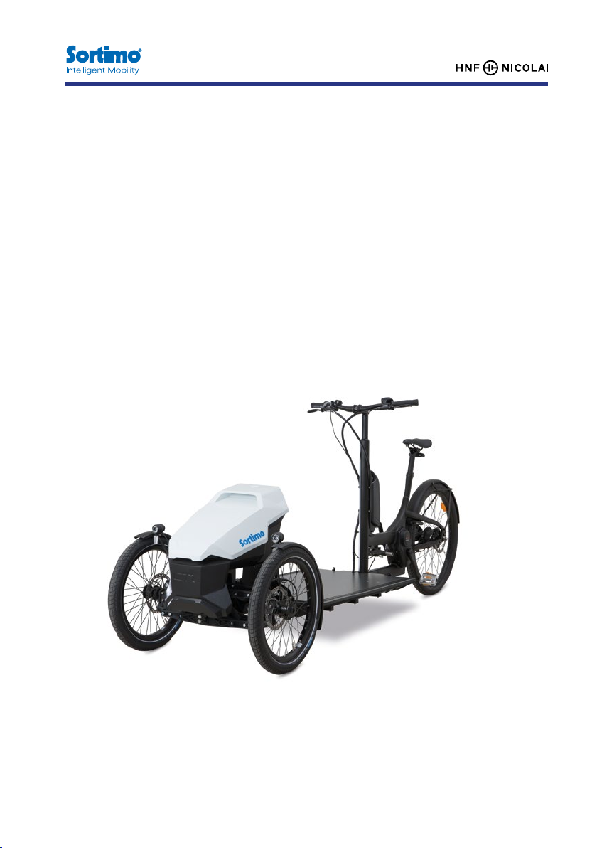
Sormo ProCargo CT1
Operang Instrucons
Page 2

Manufacturer:
HNF GmbH
Bahnhofstraße 150
16359 Biesenthal
Deutschland
Mail: [email protected]
Web: hnf-nicolai.com
V1.5, Juni 2018
Layout, photos and text: HNF GmbH, Berlin, Deutschland
The menoned brands are subject to property rights and are the property of
their respecve owners even without further labelling. Reproducon in whole or in
part is prohibited without prior wrien consent. Subject to prinng errors, mistakes
and technical changes. Please note that the actual product may dier from the
image shown.
2 3
Page 3

Table of Contents
1.
2. Inial set-up 11
3. Before every ride 15
4. Operaon 18
5. Ergonomic seng 46
Your vehicle 7
1.1. Intended use 7
1.2. Tilng 9
1.3. Safe loading 10
1.4. Scope of delivery 11
1.5. Installing accessories 11
2.1. Adjusng the saddle height 12
2.2. Adjusng handlebar height 13
2.3. Removing/installing the baery 13
2.4. Switching the drive on/o 14
2.5. Adjusng the assistance level 14
2.6. Switching the light on/o 14
2.7. Push-assistance 14
2.8. Bedding in the disc brakes 15
3.1. Checking the tyres 15
3.2. Checking steering and lt kinema cs 16
3.3. Checking the brake system 16
3.4. Checking the drive belt 17
3.5. Baery: Ensuring secure xing and charging status 17
3.6. Checking the screw ngs 17
3.7. Checking the lights 17
4.1. Bosch eBike system 18
4.1.1. Purion on-board computer 18
4.1.2. Drive Unit CX 26
4.1.3. Baery 32
4.1.4. Baery charger 38
4.2. NuVinci Harmony gear hub 43
4.3. Gates Carbon Drive Belt 43
4.4. Brake system 44
4.5. Frame lock on rear wheel 45
4.6. Pannier holders 46
5.1. Horizontal saddle posion and lt 46
5.2. Adjus ng grip distance of the brake lever 47
6. Maintenance 47
6.1. List of wear parts 48
6.2. Recommended maintenance intervals 48
6.3. Aer an accident 49
6.4. Baery 49
6.5. Tyers 50
6.6. Changing tyres/tubes 50
6.6.1. Front wheels 50
6.6.2. Removing the rear wheel 51
6.6.3. Changing the tyre/tube 52
6.6.4. Fing the rear wheel 52
6.7. Calibrang the NuVinci Harmon 53
6.8. Brakes 53
6.8.1. Wear of brake pads and brake discs 54
6.8.2. Checking the brake pads 54
7. Cleaning and care 55
8. Technical specicaons 56
8.1. Comonent list 56
8.2. Weights 56
8.3. Tightening torque of screws 57
8.4. Frame number and nameplate 57
9. Liability for defects 58
10. EC Declaraon of Conformity 59
11. Disposal 60
4 5
Page 4
Your vehicle
Content and symbols used in this manual
This manual contains important informa on which will increase safety, ensure
a long service life of the pedelec and enhance your riding experience with
the ProCargo CT1.
Failure to observe the contents of this manual may result in personal injury and
damage to the vehicle.
The following symbols are used in the manual:
Aenon!
This symbol indicates a possible hazard. Observe the safety-relevant
informaon!
Informaon
This indicates useful informaon regarding handling of the product.
Important informaon!
The manual for your Sormo ProCargo CT1 is revised regularly to ensure
its validity. This manual reects the knowledge base at the me of
going to press. We therefore recommend that you visit our website at
www.mysormo.com/procargo to familiarise yourself with any changes.
The latest manual can also be downloaded here in PDF format.
1. Your vehicle
The Sormo ProCargo CT1 is a pedelec11, which is a bicycle that assists the rider
with an electric motor. This assistance is adapted via a control which evaluates the
data from three sensors22 and regulates the motor based on the selected level of
assistance. The electric motor switches o when a speed of 25 km/h is reached.
However, you can ride faster than 25 km/h on your own without electric motor
assistance.
In Europe, the pedelec is legally classed as a bicycle33. It does not have to be
approved and does not require an insurance plate. The rider does not require a
licence. For your own safety, we recommend that you wear a suitable helmet
and protecve glasses at all mes.
The maximum climbing performance of the vehicle is dependent upon various
parameters, including cargo load, tness of the rider and charging status of
the baery.
With a fully charged baery and rider in good condion, climbing performance is
ancipated as follows: 18 % (80 kg rider without load) to 7% (100 kg rider + 140 kg
cargo load).
This climbing performance is reduced with charging status of the baery < 30%.
1.1. Intended use
Your Sormo ProCargo CT1 is designed to carry one person and load on asphalt
roads and fored paths through woods and elds. The cargo loads are approved
as follows:
Rider weight: 100 kg
Cargo loading area: 140 kg
1 Pedal Electric Cycle
2 Sensors: Speed, cadence, torque
3 Regulaon 168/2013, arcle 2, (2) h)
6 7
Page 5
Your vehicle Your vehicle
The ProCargo CT1 is not designed for the following:
• Transportaon of a person on the loading area (transportaon of a child
in suitable seang possible, refer to 1.5 „Fing of accessories“)
• Race/compeon use
• Cleaning with a water jet
• Charging of the baery outdoors in wet condions
• Use of a trailer
Intended use is further limited by:
• the safety informa on in this manual
• the „Technical specicaons“ chapter in this manual
• the road trac regulaons valid for the respecve country of use
• the road trac licensing regulaons valid for the respecve country of use
Use of the cargo bike is not recommended for the following user groups:
• People with limited physical, sensory or intellectual capacies
• People who cannot operate the vehicle safely due to their physique
If you increase the maximum assistance speed from 25 km/h by tuning,
the vehicle is no longer classed as a pedelec, but rather a small moped.
Tuning may result in negave consequences in a variety of legal areas.
For example, accidents with a tuned pedelec will not be covered by
personal liability insurance.
-> Please refrain from tuning.
The ProCargo CT1 is considerably longer and wider than a convenonal
bicycle.
-> Inially, manoeuvring your ProCargo CT1 should be pracsed in a
locaon relavely free of trac, as described in the following secon,
-> Switching the light on during travel will allow other road users to
gauge the size of the ProCargo CT1.
Please check your country specic requirements concerning lighng devices and
decide which passive re ectors are necessary to be mounted.
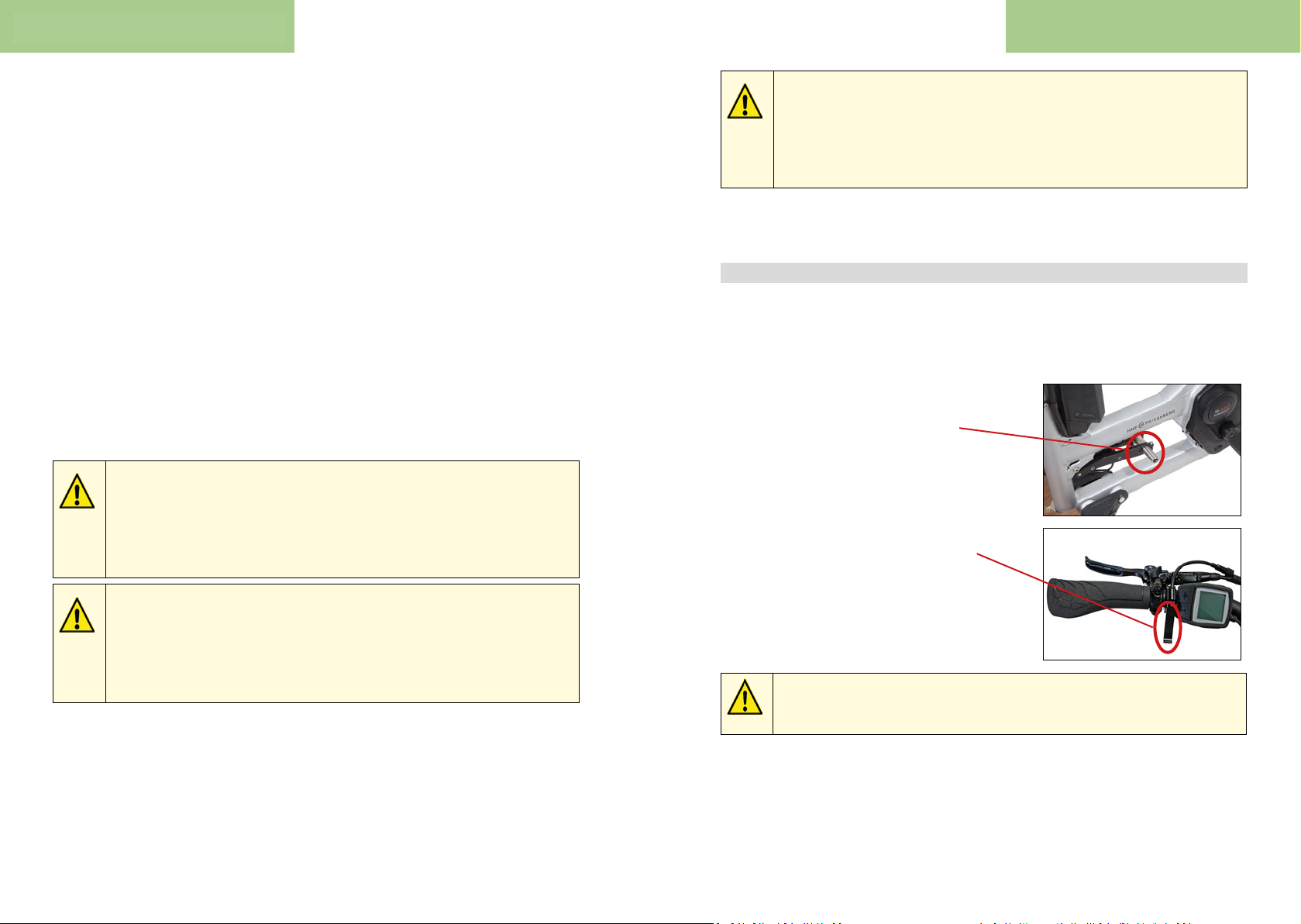
1.2. Tilng
The lng system installed on the ProCargo CT1 will ensure impressive agility at
greater travel speeds. Tilng system can be blocked via foot lever for parking (and
loading) and to facilitate the starng procedure.
Blocking the lng system:
Push the lever all the way down with the foot.
Blocking engages when the vehicle is
fully erected.
Unblocking the lng system:
Actuate the hand lever with one nger.
Rotang parts such as wheels, sprockets, cranks or pedals can draw items
of clothing, items being carried or even body parts into the mechanism.
If you slip o the pedals, your foot could get tangled in the spokes.
This can cause serious accidents!
-> Wear close-ng clothing.
-> Wear shoes with a at sole which provides good grip.
Familiarise yourself with the lng system of the ProCargo CT1 in an area with minimal trac. Pracce without load to begin with, and then connue with load added:
The vehicle should not be manoeuvred faster than walking pace with
the lng system blocked.
-> Disengage blocking of the lng system when starng o !
• Block the lng system with the foot lever.
• Commence movement, and at the same me disengage blocking of
the lng system with the hand lever.
8 9
Page 6
Your vehicle Your vehicle
We recommend starng o with a higher assistance level in order that a
stable speed is more quickly aained.
Please be aware that the possible lng is technically limited, even
with disengaged lng system. Once this limit has been reached, a curve
can not be traversed any more acutely.
-> Familiarise yourself with this limit range on an open area with no
other trac
In an unloaded condion, the axle load is minimal on the front wheels.
The front wheels are blocked extremely quickly with heavy front braking.
Front wheels blocked in curves will lead to understeer, the vehicle slides
forwards in a direct line.
-> The rear brake should be predominantly applied in an unladen
condion and the front brakes applied only tentatvely.
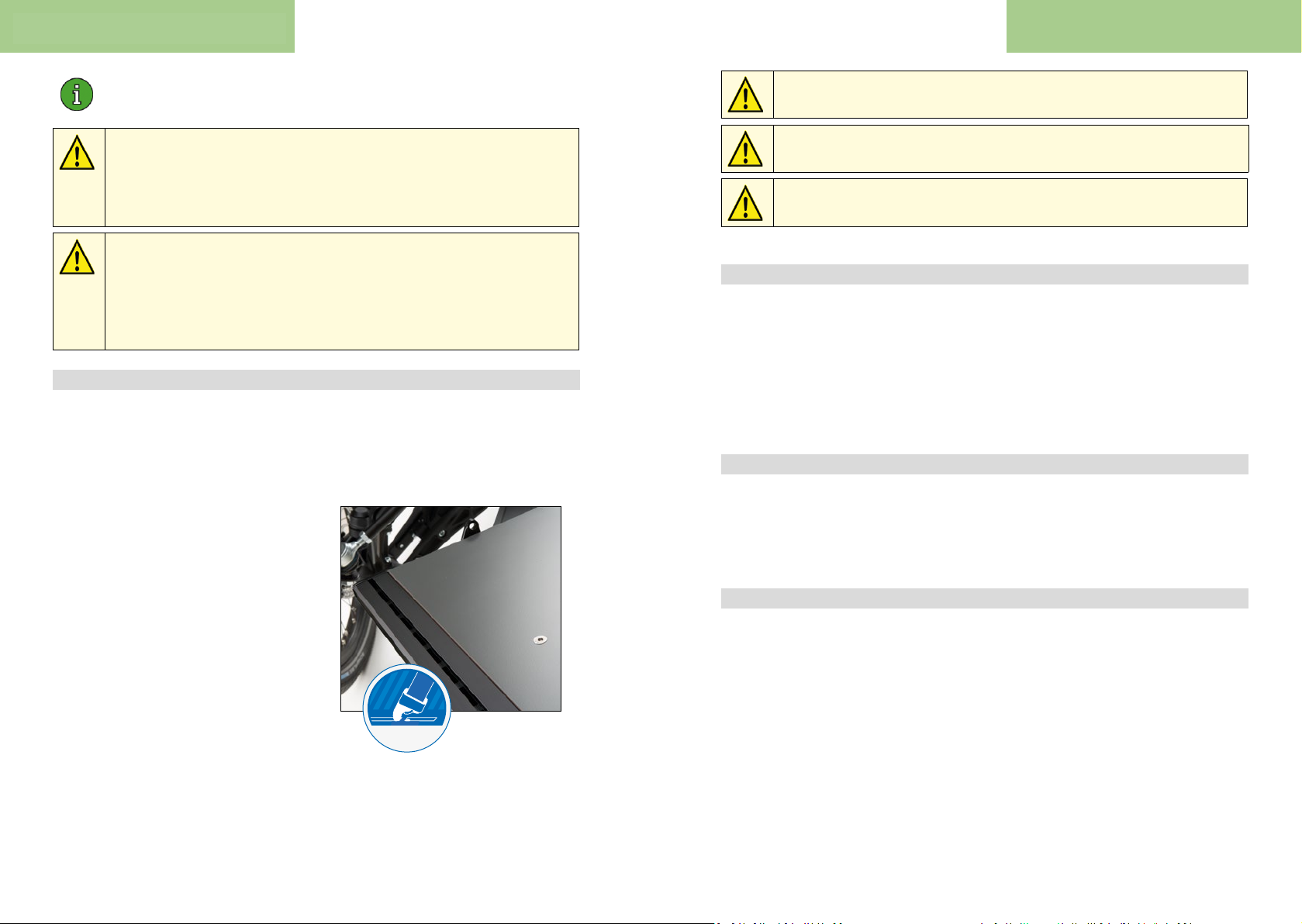
1.3. Safe loading
The following principles should be observed when loading:
• Ensure a stable posion of the vehicle during loading. Lock the lng
system and one or both holding brakes as required.
• Maintain a low centre of gravity
for the load. If several items
are being placed on the loading
area, always place the heavier
items at the boom.
• Secure the cargo. Use the
appropriate ProSafe Rail with
the matching one and approved
accessories. Only allowed
Sormo lashing straps with
clamp buckle.
PROSAFE
Loads which are permied to move freely around the loading area can
lead to accidents. -> Secure the load with lashing strap(s).
Do not secure the lashing straps onto parts of the steering/lng system,
as this could impair funconing of the steering/lng system.
The loading area or other parts of the vehicle must not become
misshapen as a direct result of lashing straps.
1.4. Scope of delivery
• Baery charger
• 2 keys for frame lock/baery lock
• Transport locks for the Tektro brake discs
• Bosch hazardous goods box for shipping the baery
• Two yellow spoke reectors for the rear wheel
• Manuals of select component manufacturers
1.5. Installing accessories
Mount only approved and tested for the ProCargo CT1equipment.
The required accessories can be obtained from your Sormo partner or in the
online shop of Sormo under mySormo.com/ProCargo.
2. Inial set-up
This chapter explains how to get your ProCargo CT1 ready for the road.
• Firstly, you should inate the tyres. The recommended air pressure
can be obtained in secon 3.1.
• We recommend adjusng the saddle height rst (2.1), and then
the handlebar height accordingly (2.2).
• If necessary, the brake locking must be released prior to commencing
inial travel, refer to secon 4.4.
10 11
Page 7
Inial set-upInial set-up
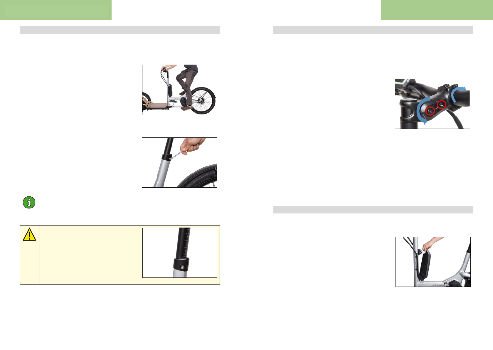
2.1. Adjusng the saddle height
The saddle height is a decisive inuenal factor on eciency of the power you
exert on the pedelec.
Saddle height is correct when your leg is almost
straight with the ball of your foot on the pedal.
The crank arms are thereby aligned vercally.
Block the lng system when checking the
saddle height to prevent toppling.
To change the saddle height, proceed as follows:
• Connue to loosen the seatpost clamping screw with an Allen key unl it is
possible to adjust the saddle height.
• Then ghten the screw with a torque of
5-7 Nm using the Allen key.
The seatpost clamping screw is ghtened suciently when the seatpost
can not be turned or when it no longer slides down into the seat tube
under your weight.
2.2. Adjusng handlebar height
The ProCargo CT1 is equipped with a stem adjustable in height. In the delivery
condion, the stem is screwed into its lowermost posion (-20°). The height of the
stem can be increased by up to 11.5 cm by adjusng the angle of the stem
(max. angle 60°). To adjust the height of the stem, proceed as follows:
• Connue to loosen both screws marked
in red unl it is possible to turn the
stem.
• Set the desired angle and note the
dierence in angle.
• Tighten the screws marked in red once
again with 14-15 Nm.
In the second step, the handlebar must also be
turned around this dierence in angle in the
opposite direcon, indicated by the right-hand
semicircular arrow:
• Loosen all 4 screws on the clamping plate of the stem unl it is possible
to turn the handlebar.
• Turn the handlebar around the dierence in angle opposite to that noted.
• Reghten all 4 handlebar clamping screws of the stem with 6 Nm.
2.3. Removing/installing the baery
If you pull the seatpost out too far, the
upper part of the seat tube may sustain
damage which could lead to breakage.
There is a risk of accident or injury!
-> Pull out the seatpost unl the
marking for minimum inseron depth
is only just visible.
Removing the baery:
• Ensure that the system is switched o.
• Turn the key around a quarter of a turn
in the lock while at the same me pping
the baery out of the upper holder.
• Li the baery out of the holder.
Installing the baery:
• Place the baery with the contacts on the lower holder and lt it into the
• upper holder so that it clicks into place.
12 13
Page 8
Inial set-up
Before every ride
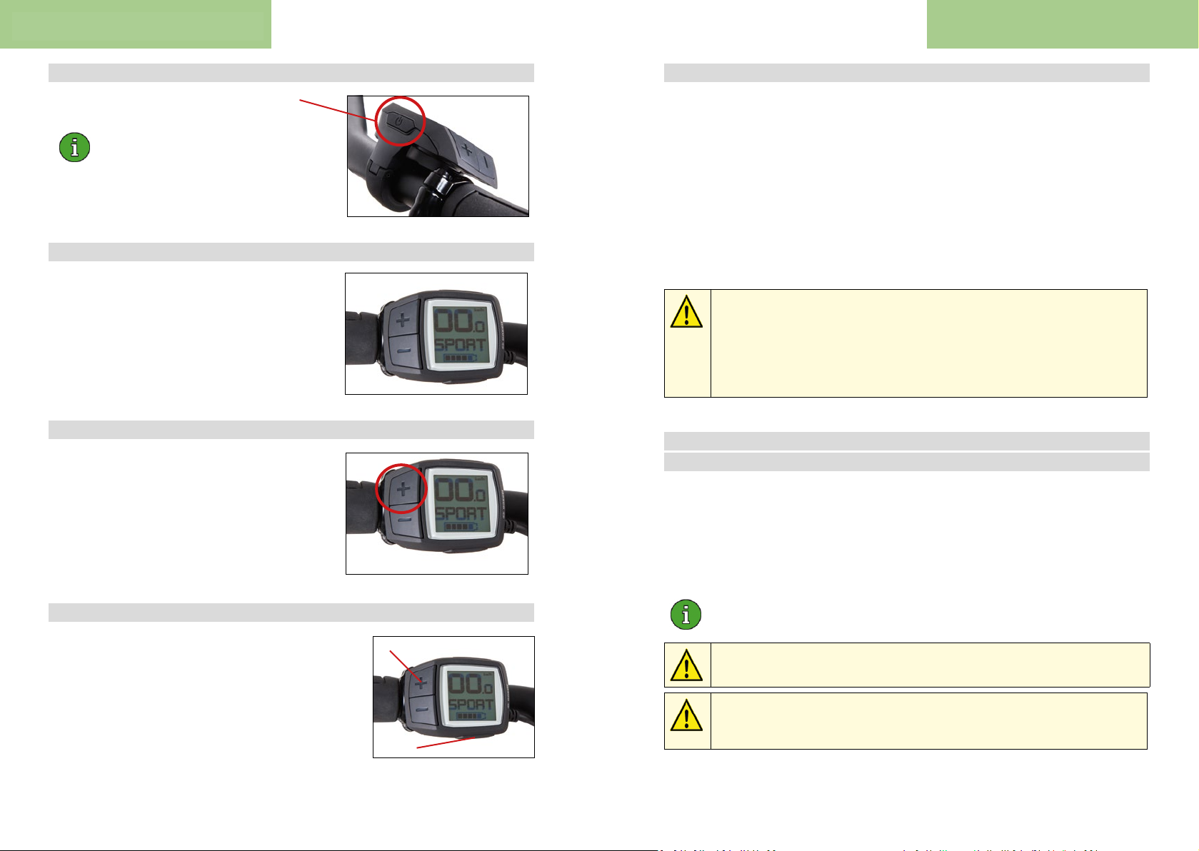
2.4. Switching the drive on/o
Press the On / O buon on the Purion to
switch on the system.
Alternavely, you can also turn on the
drive by pressing the buon on the
baery. This method also works if the
buon cell in the Purion is empty.
2.5. Adjusng the assistance level
To increase the assistance level, press the „+“
buon on the Purion unl the desired assistance
level appears in the display.
To reduce the assistance, press the „–“ buon
2.6. Switching the light on/o
Hold the „+“ bu on of the Purion pressed
(1 to 2.5 seconds) unl the light is switched on.
Hold the „+“ bu on of the Purion pressed longer
(more than 2.5 seconds) to switch o the light.
2.8. Bedding in the disc brakes
When delivered, your brake system inially exhibits only a weak braking acon
as the surfaces of brake disc and brake pads have not yet been bedded in.
For your new pedelec, as well as following replacement of brake disc and brake
pads, the disc brakes should be bedded in as follows:
• Accelerate the vehicle to approx. 25 km/h
• Decelerate to a standsll using both brakes (avoid locking of the brakes)
• Repeat this procedure unl a sasfactory improvement in braking acon
is eected. Repeat this procedure according to brake manufacturer
Tektro 30-40 mes.
In an unloaded condi on, the axle load is minimal on the front wheels.
The front wheels are blocked extremely quickly with heavy front braking.
Front wheels blocked in curves will lead to understeer, the bike slides
forwards in a direct line.
-> The rear brake should be predominantly applied in an unloaded
condi on and the front brakes applied only tenta vely.
3. Before every ride
3.1. Checking the tyres
Air pressure:
Schwalbe prescribes 2-4 bar as the permissible pressure range for both tyres.
With a maximum cargo load of 240 kg, all 3 tyres should be inated to 4 bar.
The pressure may be reduced for lighter loads.
2.7. Push-assistance
The push-assistance helps you to push the
pedelec a maximum 6 km/h (the highest rao
of the NuVinci gear hub, otherwise accordingly
slower). This is acvated by successively pressing
the „Walk bu on“ and the „+“ buon .
We recommend that you check the pressure weekly as connuous
pressure loss is inevitable for bicycle inner tubes.
If the tyre pressure is too low, the risk of snakebite punctures increases.
The result of a snakebite puncture is a at tyre.
A tyre damaged by cracks or entrenched foreign objects may lead to a
loss of pressure. There is a risk of accident!
-> Check for cracks or foreign objects in the tyre.
14 15
Page 9

Before every ride Before every ride
3.2. Checking steering and lt kinema cs
Perform three tests prior to commencing travel:
1) Blocking of lng system and unlocking must be fully funconal
2) Steering and lt must exhibit freedom-of-movement without restricon
• Block the lng system and turn the handlebar to both sides.
• Disengage the lng system, hold the handlebar securely in the travel
posion and p the pedelec to both sides.
• Ensure that both movements can be performed without restricon.
Should this not be possible, inspect the front secon of the vehicle for any
objects which may be impairing lng/steering of the vehicle and remove
them accordingly.
3) Steering must funcon without play
• Block the lng system with the foot lever.
• Push the bike against a wall with both front wheels and lock the brakes
of the front wheels.
• Now turn the handlebar. If play is clearly evident in the steering
transmission, please consult the Sormo Service Team.
3.3. Checking the brake system
The pressure point is dened as the posion of the lever stroke at which
the brake responds. If the brake is working perfectly, i.e. there are no air
bubbles in the hydraulic line, the pressure point will be at the same lever
posion for each braking procedure.
Do not touch the brake discs with your hands. The thin lm of oil on
your skin transfers to the brake discs and temporarily impairs the braking
force.
3.4. Checking the drive belt
The Gates Carbon Drive is a maintenance-free, durable system. Nevertheless,
the following points must be considered
• Are there any foreign objects between socket and belt?
• If yes: Remove immediately.
• Is the belt heavily contaminated?
• If yes: Rinse clean with water.
3.5. Baery: Ensuring secure xing and charging status
Ensure that the baery is securely xed in the lock and assess whether the charging
status is sucient for your planned journey.
• Perform a brake test at a standsll prior to every ride. In this regard, pull
the brake lever towards the handlebar with two ngers and normal braking
force. The brake lever should not come into contact with the handlebar
grip, and the brake must be capable of blocking the wheel.
• Move the ProCargo CT1 back and forth with the brake applied.
• No signicant play should be evident. Idenfy the cause of any play
determined.
• For hydraulic disc brakes, the pressure point on the brake lever must be
stable. If the pressure point is not reached aer two-thirds of the lever
stroke, pull the lever several mes in succession („pumping“). Check
whether the pressure point sens. If so, and if the locaon of the
pressure point moves during travel, the brake system must be bled by
Sormo Service Team or by a qualied specialist workshop.
• The brake discs must be free of oil. Any oil evident on the brake discs
can be removed with alcohol.
3.6. Checking the screw ngs
Ensure that the threaded axle is securely ghtened on the rear wheel and that the
following parts can not be turned:
• Saddle
• Seatpost
• Handlebar
• Stem
3.7. Checking the lights
Headlight so that other road users do not become blinded by the glare.
16 17
Page 10
Bosch operang instrucons Bosch operang instrucons
ALK
L
A
(
(
(
| 3
ALK
4. Operaon
In this chapter, operaon of the individual ProCargo CT1 components is described in
more detail.
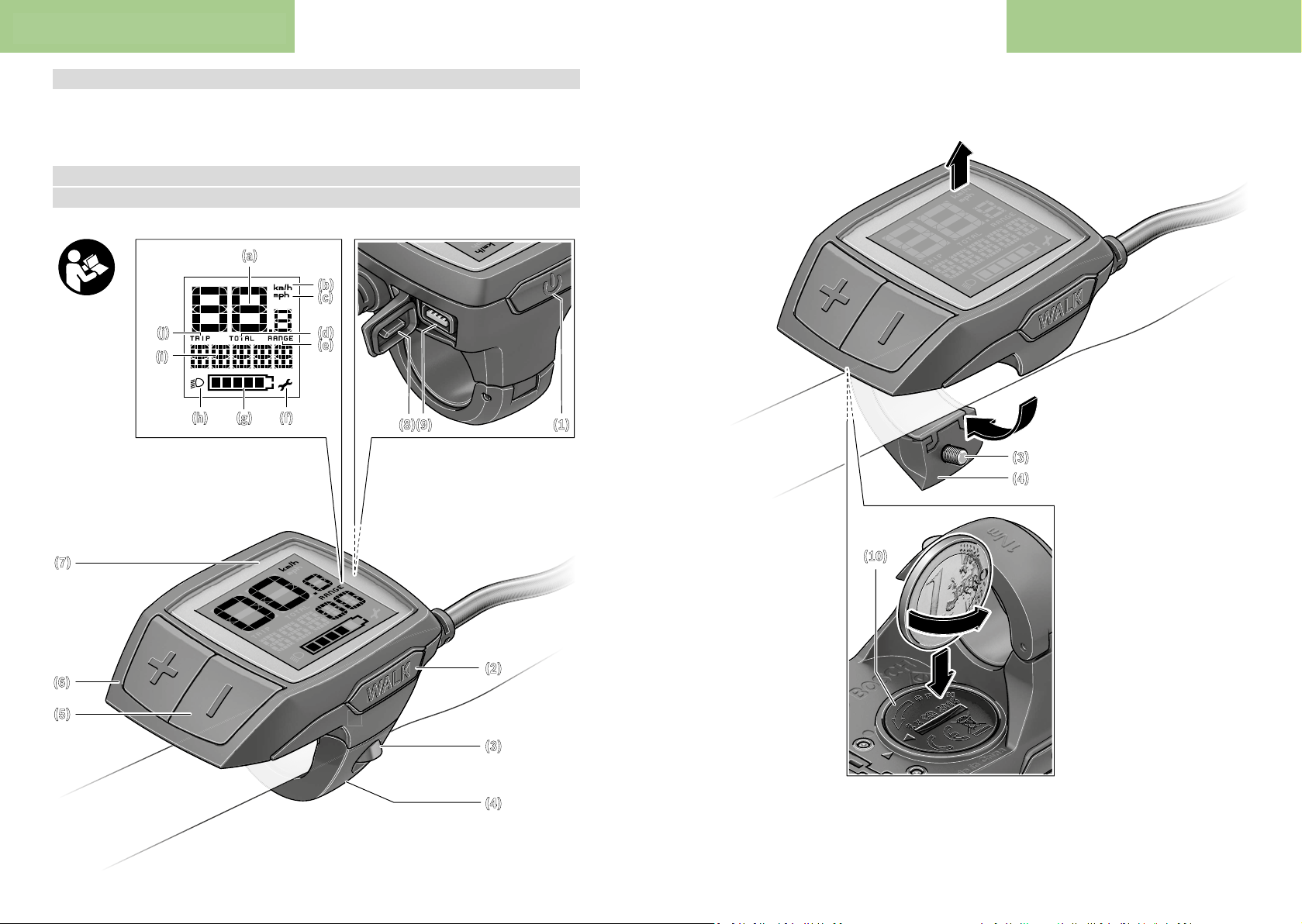
4.1. Bosch eBike system
4.1.1. Purion on-board computer
(a)
(b)
(c)
(j)
(i)
(h) (g) (f)
7)
(d)
(e)
(8)(9) (1)
(10)
(3)
(4)
WALK
WALK
WALK
6)
WALK
WALK
5)
WALK
(2)
(3)
(4)
18 19
Page 11
Bosch operang instrucons Bosch operang instrucons
Safety instructions
English – 1
English – 2
The drive is activated as soon as you start pedalling (except
To activate push assistance, briefly press the WALK button
Read all the safety information and instructions. Failure to observe the safety in-
Save all safety warnings and instructions for future reference.
The term battery is used in these instructions to mean all
original Bosch eBike rechargeable battery packs.
u Do not allow yourself to be distracted by the on-board
computer's display. If you do not focus exclusively on
the traffic, you risk being involved in an accident. If you
want to make entries in your on-board computer other
than switching the assistance level, stop and enter the appropriate data.
u Read and observe the safety warnings and directions
contained in all the eBike system operating instructions and in the operating instructions of your eBike.
formation and follow instructions may result
in electric shock, fire and/or serious injury.
Product description and
specifications
Intended use
The Purion on-board computer is designed to control Bosch
eBike systems and display riding data.
In addition to the functions shown here, changes to software
relating to troubleshooting and functional enhancements
may be introduced at any time.
Product features
The numbering of the components shown refers to the illustrations on the graphics pages at the beginning of the
manual.
Individual illustrations in these operating instructions may
differ slightly from the actual conditions depending on the
equipment of your eBike.
On/off button for on-board computer
(1)
(2) Push assistance button WALK
Fastening screw for on-board computer
(3)
Holder for on-board computer
(4)
(5) Decrease assistance level button –
(6) Increase assistance level button +
Display
(7)
Protective cap for USB port
(8)
USB diagnostic port (for servicing purposes only)
(9)
Battery compartment cover
(10)
Display elements of on-board computer
Speedometer
(a)
km/h unit indicator
(b)
mph unit indicator
(c)
(d) Total distance indicator TOTAL
(e) Range indicator RANGE
(f)
Service indicator
Battery charge indicator
(g)
Illumination indicator
(h)
Assistance level indicator/value indicator
(i)
(j) Trip distance indicator TRIP
Technical data
On-board computer Purion
Product code BUI210
A)
Batteries
Operating temperature °C –5...+40
Storage temperature °C –10...+50
Protection rating
Weight, approx. kg 0.1
We recommend using the batteries offered by Bosch. You can
A)
purchase them from your bicycle dealer
(article number: 1 270 016 819).
When the USB cover is closed
B)
The Bosch eBike system uses FreeRTOS
(see http://www.freertos.org
B)
).
IP54 (dust and splash
Operation
Symbols and their Meaning
Symbol Explanation
Short button press (less than 1 second)
Medium button press (between 1 second
and 2.5 seconds)
Long button press (longer than
2.5seconds)
Start-up
Prerequisites
The eBike system can only be activated when the following
requirements are met:
– A sufficiently charged battery is inserted (see battery op-
erating instructions).
– The speed sensor is connected properly (see drive unit
operating instructions).
Switching the eBike system on/off
The following options are available for switching on the
eBike system:
– Press the on/off button (1) of the on-board computer
with the eBike battery inserted.
– Press the on/off button of the eBike battery (see battery
operating instructions).
BUI215
2 × 3 V CR2016
proof)
if you are using the push-assistance function or if the assistance level is set to OFF). The motor output depends on the
settings of the assistance level on the on-board computer.
As soon as you stop pedalling when in normal operation, or
as soon as you have reached a speed of 25/45km/h, the
eBike drive switches off the assistance. The drive is automatically reactivated as soon you start pedalling again and the
speed is below 25/45 km/h.
The following options are available for switching off the
eBike system:
– Press the on/off button (1) of the on-board computer.
– Switch off the eBike battery using its on/off button (bi-
cycle manufacturer-specific solutions are possible when
there is no access to the battery on/off button; see the bicycle manufacturer operating instructions).
The system shuts down after being switched off; this takes
approximately three seconds. It cannot be switched back on
until shutdown has been completed.
If the eBike is not moved for approx. 10 min and no button is
pressed on the on-board computer, the eBike system
switches off automatically in order to save energy.
Note: Always switch off the eBike system when you park the
eBike.
Note: If the batteries of the on-board computer are empty,
you can still switch on your eBike using the bike’s battery. It
is, however, recommended that you replace the internal batteries as soon as possible in order to avoid damage.
Energy supply of the on-board computer
The on-board computer is supplied with voltage by two
CR2016 button cells.
Changing the batteries (see figure A)
If the on-board computer shows LOW BAT on the display,
remove the on-board computer from the handlebars by unscrewing the fastening screw (3) of the on-board computer.
Open the battery compartment cover (10) using a suitable
coin, remove the used batteries and insert new CR 2016
batteries. You can obtain the batteries recommended by
Bosch from your bicycle dealer.
When inserting the batteries, ensure that the polarity is correct.
Close the battery compartment again and fasten the onboard computer to your eBike’s handlebars using the fastening screw (3).
Switching the push assistance on/off
The push assistance aids you when pushing your eBike. The
speed in this function depends on the selected gear and can
reach a maximum of 6 km/h. The lower the selected gear,
the lower the speed of the push assistance function (at full
power).
u The push assistance function must only be used when
pushing the eBike. There is a risk of injury if the wheels
of the eBike are not in contact with the ground while using
the push assistance.
on your on-board computer. After activation, press the +
button within 3s and keep it pressed. The eBike drive is
switched on.
The push assistance is switched off as soon as one of the
following occurs:
– You release the + button;
– The wheels of the eBike are locked (e.g. by applying the
brakes or hitting an obstacle);
– The speed exceeds 6 km/h.
Note: The push assistance cannot be activated at assistance
level OFF.
Note: On some systems, the push assistance can be started
directly by pressing the WALK button.
Setting the assistance level
You can set the level at which the eBike drive assists you
while pedalling on the on-board computer. The assistance
level can be changed at any time, even while cycling.
Note: In some models, the assistance level may be preset
and cannot be changed. There may also be fewer assistance
levels available than stated here.
If the manufacturer has configured the eBike with eMTB
Mode, the assistance level SPORT is replaced by eMTB. In
eMTB Mode, the assistance factor and torque are dynamic-
ally adjusted according to the force you exert on the pedals.
eMTB Mode is only available for Performance Line CX
drives.
The following assistance levels are available as a maximum:
– OFF: Motor assistance is switched off. The eBike can just
be moved by pedalling, as with a normal bicycle. The
push assistance cannot be activated at this assistance
level.
– ECO: Effective assistance with maximum efficiency, for
maximum range
– TOUR: Steady assistance, long range for touring
– SPORT/eMTB:
SPORT: Powerful assistance, for mountain biking and for
cycling in urban traffic
eMTB: Optimum assistance whatever the terrain, rapid
acceleration when starting from a standstill, improved dy-
namics and top performance
– TURBO: Maximum assistance even at high pedalling
speeds, for biking sports
To increase the assistance level, briefly
ton+ (6) on the on-board computer repeatedly until the required assistance level appears on the indicator (i). To de-
crease the assistance level briefly press
If the display is set to TRIP, TOTAL or RANGE, the selected
assistance level will only be superimposed briefly(for approx. one second) on the display when switching over.
press the but-
the button– (5).
Switching bicycle lights on/off
For the model which has the bike lights powered by the
eBike system, a medium-length press
of the button+ will
20 21
Page 12
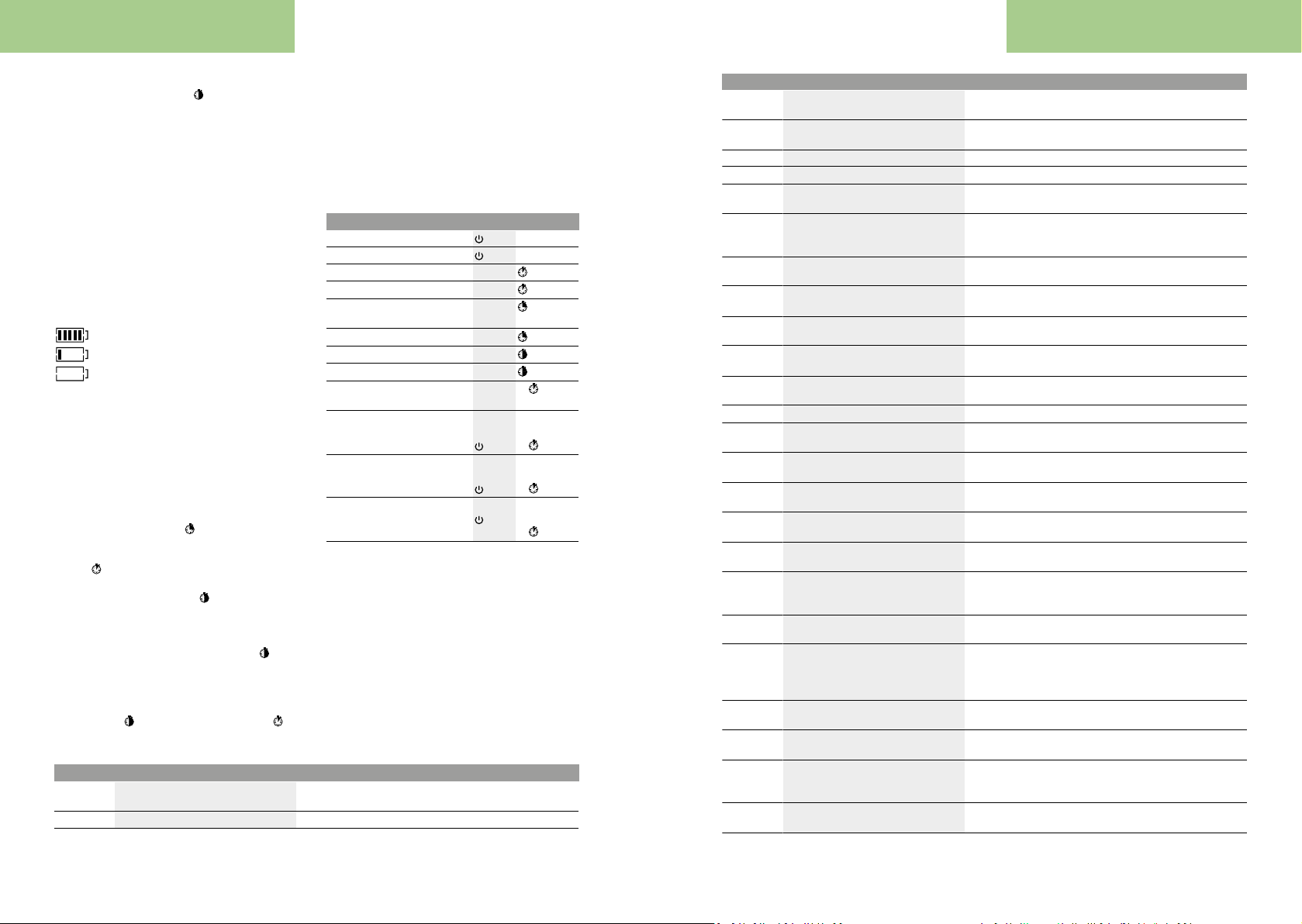
Bosch operang instrucons Bosch operang instrucons
switch on the front and rear lights simultaneously. To switch
off the bike lights, press and hold
The lighting symbol
The on-board computer saves the light status and activates
this saved status accordingly after a restart.
Switching the bike light on and off has no effect on the back
lighting of the display.
Displays and configurations of the
on-board computer
Battery charge indicator
The battery charge indicator
of the eBike battery. The state of charge of the eBike battery
can also be checked on the LEDs of the battery itself.
Each bar of the battery symbol on the indicator
ents approximately 20% of the capacity:
Speed and distance indicators
The speedometer
Indicator
peated medium-length presses
the trip distance
range of the battery
pressing
To
and simultaneously press and hold
The display will initially show
both buttons, the trip distance
To
range
tons
continue to press both buttons, the trip distance
set to
You can switch the displayed values from kilometres to miles
by holding down
on/off button
English – 3
English – 4
(h) is displayed when the light is on.
the button+.
(g) displays the state of charge
The eBike battery is fully charged.
The eBike battery should be recharged.
The LEDs of the battery charge indicator on the
battery go out. The capacity for assisting the drive
has been used up, and assistance is gently
switched off. The remaining capacity is made
available for the lighting. The indicator flashes.
The capacity of the eBike battery is enough for
about two hours of lighting.
(a) always displays the current speed.
(i) always displays the last setting as standard. Re-
of the button – will display
TRIP, the total distance TOTAL and the
RANGE one after the other. (Briefly
the button – will decrease the assistance level.)
reset the trip distance TRIP, select the trip distance TRIP
the buttons + and –.
RESET. If you continue to press
TRIP will be set to 0.
reset the range of the battery RANGE, select the battery
RANGE and simultaneously press and hold the but-
+ and –. The display will initially show RESET. If you
0.
the button – and briefly pressing the
(1).
Code Cause Corrective measures
410 One or more buttons of the on-board com-
puter are disabled.
414 Operating unit connection problem Have the connections checked
(g) repres-
TRIP will be
The versions of the subsystems and their model part numbers can be displayed for the purposes of servicing,
provided the subsystems divulge this information (dependent on the subsystem). With the system switched off, simultaneously press the buttons – and + and then press the on/
off button (1).
The USB port is reserved for connecting diagnostic systems.
The USB port does not have any other function.
u The USB connection must always be completely
sealed with the protective cap (8).
Action Buttons Duration
Switch on on-board computer Any
Switch off on-board computer Any
Increase assistance
Decrease assistance
Display TRIP, TOTAL, RANGE,
assistance modes
Switch on bike lights
Switch off bike lights
Reset trip distance
Activate push assistance
Implement push assistance
Switch from kilometres to miles
Display the versions
Adjust display brightness
The eBike system must be switched off.
A)
The information is shown as scrolling text.
B)
The display must be switched off.
C)
A)B)
+
–
–
+
+
– +
1.
WALK
2. Any
+
1. Keep
–
pressed
2.
1. Keep
– +
pressed
– +
– or +
2.
1. Keep
pressed
2.
C)
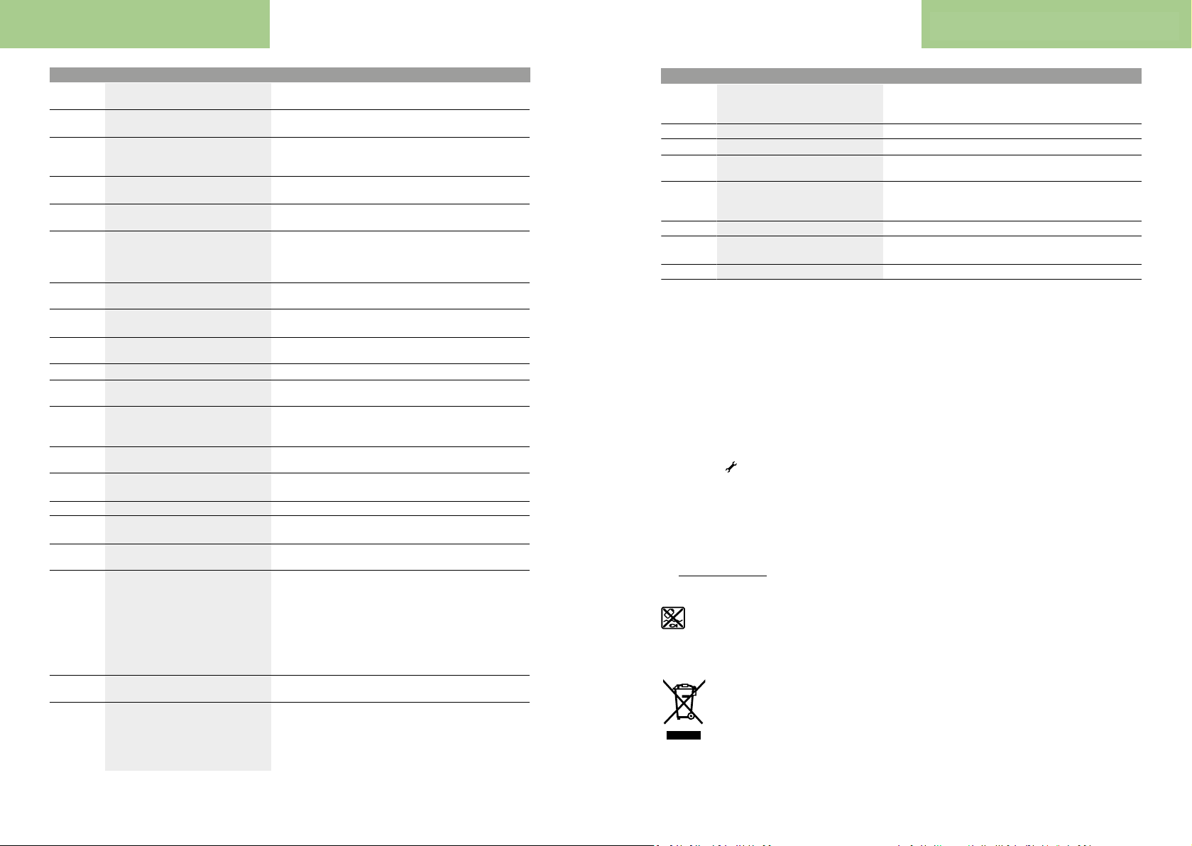
Error code display
The eBike system's components are continuously and automatically monitored. If an error is detected, the corresponding error code is displayed on the on-board computer.
The drive may be automatically shut down, depending on the
type of error. However, if you wish to continue cycling, you
will always be able to do so without assistance from the
drive. Before undertaking any other journeys, the eBike
should be checked.
u Have all repairs performed only by an authorised bike
dealer.
Check whether any buttons are stuck, e.g. as a result of dirt finding
its way in. Clean the buttons if need be.
Code Cause Corrective measures
418 One or more buttons on the operating unit
are disabled.
419 Configuration error Restart the system. If the problem persists, contact your Bosch
422 Drive unit connection problem Have the connections checked
423 eBike battery connection problem Have the connections checked
424 Communication problem between com-
ponents
426 Internal time-out error Restart the system. If the problem persists, contact your Bosch
430 Internal battery of the on-board computer
is flat
431 Software version error Restart the system. If the problem persists, contact your Bosch
440 Internal drive unit fault Restart the system. If the problem persists, contact your Bosch
450 Internal software error Restart the system. If the problem persists, contact your Bosch
460 Error at USB port Remove the cable from the USB port of the on-board computer. If
490 Internal fault of the on-board computer Have the on-board computer checked
500 Internal drive unit fault Restart the system. If the problem persists, contact your Bosch
502 Bike light fault Check the light and the associated wiring. Restart the system. If
503 Speed sensor fault Restart the system. If the problem persists, contact your Bosch
510 Internal sensor fault Restart the system. If the problem persists, contact your Bosch
511 Internal drive unit fault Restart the system. If the problem persists, contact your Bosch
530 Battery fault Switch off the eBike, remove the eBike battery and reinsert the
531 Configuration error Restart the system. If the problem persists, contact your Bosch
540 Temperature error The eBike is outside of the permissible temperature range. Switch
550 An impermissible load has been detected. Remove the load. Restart the system. If the problem persists, con-
580 Software version error Restart the system. If the problem persists, contact your Bosch
591 Authentication error Switch off the eBike system. Remove then reinsert the battery. Re-
592 Incompatible component Use a compatible display. If the problem persists, contact your
Check whether any buttons are stuck, e.g. as a result of dirt finding
its way in. Clean the buttons if need be.
eBike dealer.
Have the connections checked
eBike dealer. With this error, it is not possible to bring up the wheel
circumference in the basic settings menu or to adjust it.
Charge the on-board computer (in the holder or via the USB port)
eBike dealer.
eBike dealer.
eBike dealer.
the problem persists, contact your Bosch eBike dealer.
eBike dealer.
the problem persists, contact your Bosch eBike dealer.
eBike dealer.
eBike dealer.
eBike dealer.
eBike battery. Restart the system. If the problem persists, contact
your Bosch eBike dealer.
eBike dealer.
off the eBike system and allow the drive unit to either cool down or
heat up to the permissible temperature range. Restart the system.
If the problem persists, contact your Bosch eBike dealer.
tact your Bosch eBike dealer.
eBike dealer.
start the system. If the problem persists, contact your Bosch eBike
dealer.
Bosch eBike dealer.
22 23
Page 13
Bosch operang instrucons Bosch operang instrucons
English – 5
English – 6
Code Cause Corrective measures
593 Configuration error Restart the system. If the problem persists, contact your Bosch
595, 596 Communication error Check the wiring to the transmission and restart the system. If the
602 Internal battery fault while charging Unplug the charger from the battery. Restart the eBike system.
602 Internal battery fault Restart the system. If the problem persists, contact your Bosch
603 Internal battery fault Restart the system. If the problem persists, contact your Bosch
605 Battery temperature error The eBike is outside of the permissible temperature range. Switch
605 Battery temperature error while charging Unplug the charger from the battery. Allow the battery to cool. If
606 External battery fault Check the wiring. Restart the system. If the problem persists, con-
610 Battery voltage error Restart the system. If the problem persists, contact your Bosch
620 Charger fault Replace the charger. Contact your Bosch eBike dealer.
640 Internal battery fault Restart the system. If the problem persists, contact your Bosch
655 Multiple battery faults Switch off the eBike system. Remove then reinsert the battery. Re-
656 Software version error Contact your Bosch eBike dealer so that they can perform a soft-
7xx Transmission fault Please observe the operating instructions provided by the trans-
800 Internal ABS fault Contact your Bosch eBike dealer.
810 Implausible signals from the wheel speed
820 Fault in the wire to the front wheel speed
821 to 826 Implausible signals from the front wheel
830 Fault in the wire to the rear wheel speed
831
833 to 835
sensor. Contact your Bosch eBike dealer.
sensor.
speed sensor.
The sensor disc may be missing, defective
or fitted incorrectly; there is a significant
difference in diameter between the front
wheel and the rear wheel; extreme riding
situation, e.g. riding solely on the rear
wheel.
sensor.
Implausible signals from the rear wheel
speed sensor.
The sensor disc may be missing, defective
or fitted incorrectly; there is a significant
difference in diameter between the front
eBike dealer.
problem persists, contact your Bosch eBike dealer.
Plug the charger into the battery. If the problem persists, contact
your Bosch eBike dealer.
eBike dealer.
eBike dealer.
off the eBike system and allow the drive unit to either cool down or
heat up to the permissible temperature range. Restart the system.
If the problem persists, contact your Bosch eBike dealer.
the problem persists, contact your Bosch eBike dealer.
tact your Bosch eBike dealer.
eBike dealer.
eBike dealer.
start the system. If the problem persists, contact your Bosch eBike
dealer.
ware update.
mission manufacturer.
Contact your Bosch eBike dealer.
Contact your Bosch eBike dealer.
Restart the system and carry out a test ride lasting at least two
minutes. The ABS indicator light must go out. If the problem persists, contact your Bosch eBike dealer.
Contact your Bosch eBike dealer.
Restart the system and carry out a test ride lasting at least two
minutes. The ABS indicator light must go out. If the problem persists, contact your Bosch eBike dealer.
Code Cause Corrective measures
wheel and the rear wheel; extreme riding
situation, e.g. riding solely on the rear
wheel.
840 Internal ABS fault Contact your Bosch eBike dealer.
850 Internal ABS fault Contact your Bosch eBike dealer.
860, 861 Fault in the power supply Restart the system. If the problem persists, contact your Bosch
870, 871
880
883 to 885
889 Internal ABS fault Contact your Bosch eBike dealer.
890 ABS indicator light is defective or missing;
No display Internal fault of the on-board computer Restart your eBike system by switching it off and back on.
Communication error Restart the system. If the problem persists, contact your Bosch
ABS may not be working.
Maintenance and servicing
eBike dealer.
eBike dealer.
Contact your Bosch eBike dealer.
Subject to change without notice.
Maintenance and cleaning
Do not immerse any components, including the drive unit, in
water or clean them with pressurised water.
Clean your on-board computer using a soft cloth dampened
only with water. Do not use any detergents.
Have your eBike system checked by an expert at least once a
year (including mechanical parts, up-to-dateness of system
software).
The bicycle manufacturer or dealer can also store a distance
travelled for the service date in the system. In this case, the
on-board computer will show you that the service date is due
by displaying (f)
Please have your eBike serviced and repaired by an authorised bicycle dealer.
.
After-sales service and advice on using products
If you have any questions about the eBike system and its
components, contact an authorised bicycle dealer.
For contact details of authorised bike dealerships, please
visit www.bosch-ebike.com
.
Disposal
The drive unit, on-board computer incl. operating unit, battery, speed sensor, accessories
vironmentally correct manner.
Do not dispose of eBikes and their components with house-
hold waste.
Please return Bosch eBike components that are no longer
usable to an authorised bicycle dealer.
and packaging should be disposed of in an en-
In accordance with Directive 2012/19/EU
and Directive 2006/66/EC respectively, electronic devices that are no longer usable and defective/drained batteries must be collected
separately and recycled in an environmentally
friendly manner.
24 25
Page 14
Bosch operang instrucons Bosch operang instrucons
Safety instructions
Observe all national regulations which set out the ap-
English – 1
2 |
OBJ_BUCH-2821-001.book Page 2 Wednesday, April 13, 2016 4:38 PM
4.1.2. Drive Unit CX
A
5
–
17 mm
1
2
3
Read all the safety information and instructions. Failure to observe the safety in-
formation and follow instructions may result
in electric shock, fire and/or serious injury.
Save all safety warnings and instructions for future reference.
The term battery is used in these instructions to mean all
original Bosch eBike rechargeable battery packs.
u Do not open the drive unit yourself. The drive unit
must only be repaired by qualified personnel using
only original spare parts. This will ensure that the safety
of the drive unit is maintained. Unauthorised opening of
the drive unit will render warranty claims null and void.
u All components fitted to the drive unit and all other
components of the eBike drive (e.g. chainring, chainring receptacle, pedals) must only be replaced with
identical components or components that have been
specifically approved by the manufacturer for your
eBike. This will protect the drive unit from overloading
and becoming damaged.
u Remove the battery from the eBike before beginning
work (e.g. inspection, repair, assembly, maintenance,
work on the chain, etc.) on the eBike, transporting it
with a car or aeroplane, or storing it. Unintentional ac-
tivation of the eBike system poses a risk of injury.
u The eBike system may switch on when the eBike is
pushed backwards.
u The push assistance function must only be used when
pushing the eBike. There is a risk of injury if the wheels
of the eBike are not in contact with the ground while using
the push assistance.
u When the push assistance is activated, the pedals may
turn at the same time. When the push assistance function is activated, make sure that there is enough space
between your legs and the turning pedals to avoid the risk
of injury.
u Use only original Bosch batteries that the manufac-
turer has approved for your eBike. Using other batteries can lead to injuries and pose a fire hazard. Bosch accepts no liability or warranty claims if other batteries are
used.
u Do not make any modifications to your eBike system
or fit any other products that might increase the performance of your eBike system. Doing so will generally
reduce the service life of the system and risks damaging
the drive unit and the bike. You also run the risk of losing
the guarantee and warranty claims on the bicycle you
have purchased. By handling the system improperly you
are also endangering your safety and that of other road
users, thus running the risk of high personal liability costs
and possibly even criminal prosecution in the event of accidents that can be attributed to manipulation of the bicycle.
u
proved use of eBikes.
u Read and observe the safety warnings and directions
contained in all the eBike system operating instructions and in the operating instructions of your eBike.
Privacy notice
When you connect the eBike to the Bosch diagnostic tool,
data about the eBike drive unit (e.g. energy consumption,
temperature, etc.) is transferred to Bosch eBike Systems
(Robert Bosch GmbH) for the purposes of product improvement. You can find more information about this on the Bosch
eBike website at www.bosch-ebike.com
Product description and
specifications
Intended use
The drive unit is intended exclusively for driving your eBike
and must not be used for any other purpose.
In addition to the functions shown here, changes to software
relating to troubleshooting and functional enhancements
may be introduced at any time.
Product features
Individual illustrations in these operating instructions may
differ slightly from the actual conditions depending on the
equipment of your eBike.
The numbering of the components shown refers to the illustrations on the graphics pages at the beginning of the
manual.
Drive unit
(1)
Speed sensor
(2)
Speed sensor spoke magnet
(3)
26 27
Page 15

Bosch operang instrucons Bosch operang instrucons
English – 2
Technical data
Inserting a bulb incorrectly can cause it to blow.
Assembly
Inserting and removing the battery
For inserting and removing the eBike battery in/from the
eBike, please read and observe the battery operating instructions.
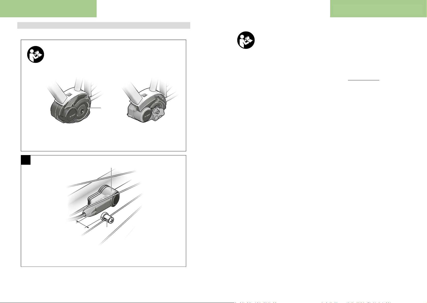
Checking the speed sensor (see figure A)
The speed sensor
ted such that the spoke magnet moves past the speed
sensor at a distance of at least 5 mm and at most 17 mm
with each rotation of the wheel.
Note:
spoke magnet
sensor
play will fail and the eBike drive unit will operate in emergency mode.
Should this occur, loosen the screw of the spoke magnet
and fasten the spoke magnet to the spoke such that it runs
past the marking on the speed sensor at the correct clearance. If the speed is still not being indicated on the speedometer display after doing this, please contact an authorised
bicycle dealer.
Setting the assistance level
English – 3
cific solutions are possible whereby there is no access to
Drive unit Active Line Performance Line Performance
Product code BDU250C
Continuous rated power W 250 250 250 250
Torque at drive, max. Nm 50 63 63 75
Rated voltage V = 36 36 36 36
Operating temperature °C -5 to +40 -5 to +40 -5 to +40 -5 to +40
Storage temperature °C -10 to +50 -10 to +50 -10 to +50 -10 to +50
Protection rating IP 54 (dust- and
Weight, approx. kg 4 4 4 4
Bicycle lights
Voltage approx.
A)
B)C)
Maximum power
– Front light W 8.4/17.4
– Taillight W 0.6/0.6
A)
Depends on legal regulations, not possible in all country-specific models via the eBike battery
B)
The voltage level is preset and can only be changed by
the bicycle dealer.
(2) and its spoke magnet (3) must be fit-
If the distance between the speed sensor (2) and the
(3) is too small or too large, or if the speed
(2) is not properly connected, the speedometer dis-
28 29
Cruise Speed
BDU250P BDU290P BDU250P CX
BDU255C
splash-proof)
IP 54 (dust- and
splash-proof)
C)
When changing the bulbs, ensure that they are compatible with the Bosch eBike system (ask your bicycle
dealer) and are suitable for the specified voltage. Bulbs
must only be replaced with bulbs of the same voltage.
Operation
Start-up
Requirements
The eBike system can only be activated when the following
requirements are met:
– A sufficiently charged battery is inserted (see battery op-
erating instructions).
– The on-board computer is properly inserted in the holder
(see on-board computer operating instructions).
– The speed sensor is correctly connected (see "Checking
the speed sensor (see figure A)", pageEnglish–2).
Switching the eBike system on/off
The following options are available for switching on the
eBike system:
– If the on-board computer is already switched on when you
(3)
insert it into the holder, the eBike system will be switched
on automatically.
– When the on-board computer and the eBike battery are
inserted, briefly press the On/Off button of the on-board
computer.
– With the on-board computer inserted, push the On/Off
button on the eBike battery (bicycle manufacturer-spe-
Line CX
IP 54 (dust- and
splash-proof)
IP 54 (dust- and
splash-proof)
V = 6/12
the battery On/Off button; see the battery operating instructions).
Note: The eBike system always starts in OFF mode for drive
units with a maximum speed of more than 25km/h.
The drive is activated as soon as you start pedalling (except
for in the push assistance function, (see "Switching the push
assistance on/off", pageEnglish–4)). The motor output
depends on which assistance level is set on the on-board
computer.
As soon as you stop pedalling when in normal operation, or
as soon as you have reached a speed of 25/45km/h, the
eBike drive unit switches off the assistance. The drive is
automatically re-activated as soon you start pedalling again
and the speed is below 25/45km/h.
The following options are available for switching off the
eBike system:
– Press the On/Off button of the on-board computer.
– Switch off the eBike battery using its On/Off button (bi-
cycle manufacturer-specific solutions are possible
whereby there is no access to the battery On/Off button;
see the bicycle manufacturer operating instructions).
– Remove the on-board computer from its holder.
If the eBike is not moved for approx. 10 min and no button is
pressed on the on-board computer, the eBike system
switches off automatically in order to save energy.
eShift (optional)
eShift is the integration of electronic gear-shifting systems
into the eBike system. The eShift components are electrically connected to the drive unit by the manufacturer. The
separate operating instructions describe how to operate the
electronic gear-shifting systems.
Assistance level Assistance factor
Active Line Performance Line Performance Line CX
ECO
TOUR
SPORT/eMTB
TURBO
A)
The assistance factor may vary in some models.
B)
Maximum value
40% 50% 55% 50%
100% 120% 120% 120%
150% 190% 190% 210% to 300%
250% 275% 275% 300%
You can set the level at which the eBike drive assists you
while pedalling on the on-board computer. The assistance
level can be changed at any time, even while cycling.
Note: In some models, the assistance level may be preset
and cannot be changed. There may also be fewer assistance
levels available than stated here.
If the manufacturer has configured the eBike with eMTB
Mode, the assistance level SPORT is replaced by eMTB. In
eMTB Mode, the assistance factor and torque are dynamic-
ally adjusted according to the force you exert on the pedals.
eMTB Mode is only available for Performance Line CX
drives.
The following assistance levels are available as a maximum:
– OFF: Motor assistance is switched off. The eBike can just
be moved by pedalling, as with a normal bicycle. The
push assistance cannot be activated at this assistance
level.
– ECO: Effective assistance with maximum efficiency, for
maximum range
– TOUR: Steady assistance, long range for touring
– SPORT/eMTB:
SPORT: Powerful assistance, for mountain biking and for
cycling in urban traffic
eMTB: Optimum assistance whatever the terrain, rapid
acceleration when starting from a standstill, improved dy-
namics and top performance
– TURBO: Maximum assistance even at high pedalling
speeds, for biking sports
The requested motor output appears on the display of the
on-board computer. The maximum motor output depends on
which assistance level is selected.
A)
Cruise Speed
B)
Page 16
Bosch operang instrucons Bosch operang instrucons
English – 4
Switching the push assistance on/off
An exception applies to the push assistance function, in
English – 5
The push assistance aids you when pushing your eBike. The
speed in this function depends on the selected gear and can
reach a maximum of 6 km/h. The lower the selected gear,
the lower the speed of the push assistance function (at full
power).
u The push assistance function must only be used when
pushing the eBike. There is a risk of injury if the wheels
of the eBike are not in contact with the ground while using
the push assistance.
To activate the push assistance, briefly press the WALK
button on your on-board computer. After activation, press
the + button within 3s and keep it pressed. The eBike drive
is switched on.
Note: The push assistance cannot be activated at assistance
level OFF.
The push assistance is switched off as soon as one of the
following occurs:
– You release the + button;
– The wheels of the eBike are locked (e.g. by applying the
brakes or hitting an obstacle);
– The speed exceeds 6 km/h.
Note: On some systems, the push assistance can be started
directly by pressing the WALK button.
Note: A speed of 18 km/h (start assistance) can be reached
on some systems.
Depending on the statutory specifications in some countries,
the push assistance function may vary from region to region.
Back-pedalling function (optional)
On bikes with a back-pedalling function, the pedals rotate
when the push assistance is switched on. If the rotating pedals are locked, the push assistance switches off.
Switching bicycle lights on/off
On the model where the bike lights are powered by the eBike
system, the front light and taillight can be switched on and
off at the same time via the on-board computer.
Notes on cycling with the eBike
system
When does the eBike drive work?
The eBike drive assists your cycling only when you are pedalling. If you do not pedal, the assistance will not work. The
motor output always depends on the pedalling force you apply.
If you apply less force, you will receive less assistance than if
you apply a lot of force. This applies irrespective of the assistance level.
The eBike drive automatically switches off at speeds over
25/45km/h. When the speed falls below 25/45km/h, the
drive automatically becomes available again.
which the eBike can be pushed at low speed without pedalling. The pedals may rotate when the push assistance is in
use.
You can also use the eBike as a normal bicycle without assistance at any time, either by switching off the eBike system
or by setting the assistance level to OFF. The same applies
when the battery is drained.
Interaction between the eBike system and gearshifting
The gear-shifting should be used with an eBike drive in the
same way as with a normal bicycle (observe the operating instructions of your eBike on this point).
Irrespective of the type of gear-shifting, it is advisable to
briefly stop pedalling when changing gear. This will facilitate
the gear change and reduce wear on the powertrain.
By selecting the correct gear, you can increase your speed
and range while applying the same amount of force.
Gaining initial experience
We recommend that you gain initial experience with the
eBike away from busy roads.
Test the various assistance levels, beginning with the lowest
level. As soon as you feel confident, you can ride your eBike
in traffic like any other bicycle.
Test the range of your eBike in different conditions before
planning longer and more demanding trips.
Influences on range
The range is affected by a number of factors, such as:
– Assistance level
– Speed
– Gear shifting behaviour
– Tyre type and tyre pressure
– Age and condition of the battery
– Route profile (gradients) and conditions (road surface)
– Headwind and ambient temperature
– Weight of eBike, rider and luggage
For this reason, it is not possible to predict the range accurately before and during a trip. However, as a general rule:
– With the same assistance level on the eBike drive: The
less energy you need to exert in order to reach a certain
speed (e.g. by changing gears optimally), the less energy
the eBike drive will consume and the higher the range per
battery charge will be.
– The higher the selected assistance level under otherwise
constant conditions, the smaller the range will be.
Taking care of your eBike
Please observe the operating and storage temperatures of
the eBike components. Protect the drive unit, on-board computer and battery against extreme temperatures (e.g. from
intense sunlight without adequate ventilation). Extreme temperatures can cause the components (especially the battery)
to become damaged.
Have your eBike system checked by an expert at least once a
year (including mechanical parts, up-to-dateness of system
software).
Please have your eBike serviced and repaired by an authorised bicycle dealer.
Maintenance and servicing
Maintenance and cleaning
When changing the bulbs, ensure that they are compatible
with the Bosch eBike system (ask your bicycle dealer) and
are suitable for the specified voltage. Bulbs must only be replaced with bulbs of the same voltage.
Do not immerse any components, including the drive unit, in
water or clean them with pressurised water.
Have your eBike system checked by an expert at least once a
year (including mechanical parts, up-to-dateness of system
software).
Please have your eBike serviced and repaired by an authorised bicycle dealer.
After-sales service and advice on using products
If you have any questions about the eBike system and its
components, contact an authorised bicycle dealer.
For contact details of authorised bike dealerships, please
visit www.bosch-ebike.com
Disposal
The drive unit, on-board computer incl. operating unit, battery, speed sensor, accessories
and packaging should be disposed of in an en-
vironmentally correct manner.
Do not dispose of eBikes and their components with house-
hold waste.
In accordance with Directive 2012/19/EU
and Directive 2006/66/EC respectively, electronic devices that are no longer usable and defective/drained batteries must be collected
separately and recycled in an environmentally
friendly manner.
Please return Bosch eBike components that are no longer
usable to an authorised bicycle dealer.
Subject to change without notice.
30 31
Page 17
Bosch operang instrucons Bosch operang instrucons
Safety instructions
Read all the safety and
general instructions. Fail-
ure to observe the safety
and general instructions
may result in electric shock,
fire and/or serious injury.
The contents of lithium-ion battery cells are flammable under
certain conditions. You must therefore ensure that you have
read and understood the rules of conduct set out in these
operating instructions.
Save all safety warnings and instructions for future reference.
The term battery is used in these instructions to mean all
original Bosch eBike rechargeable battery packs.
u Remove the battery from the eBike before beginning
work (e.g. inspection, repair, assembly, maintenance,
work on the chain, etc.) on the eBike, transporting it
with a car or aeroplane, or storing it. Unintentional ac-
tivation of the eBike system poses a risk of injury.
u Do not open the battery. There is a risk of short-circuit-
ing. Opening the battery voids any and all warranty
claims.
u Protect the battery against heat (e.g. prolonged sun
exposure), fire and from being submerged in water.
Do not store or operate the battery near hot or flammable objects. There is a risk of explosion.
u When the battery is not in use, keep it away from pa-
per clips, coins, keys, nails, screws or other small
metal objects that could make a connection from one
terminal to another. A short circuit between the battery
terminals may cause burns or a fire. Short circuit damage
which occurs in this instance voids any and all warranty
claims against Bosch.
u Avoid mechanical loads and exposure to high temper-
atures. These can damage the battery cells and cause the
flammable contents to leak out.
u Do not place the charger or the battery near flam-
mable materials. Ensure the battery is completely dry
and placed on a fireproof surface before charging.
There is a risk of fire due to the heat generated during
charging.
u The eBike battery must not be left unattended while
charging.
u If used incorrectly, liquid may leak from the battery.
Contact with this liquid should be avoided. If contact
accidentally occurs, rinse off with water. If the liquid
comes into contact with your eyes, seek additional
medical attention. Liquid leaking from the battery may
cause irritation or scalding.
u Batteries must not be subjected to mechanical shock.
There is a risk of the battery being damaged.
u The battery may give off fumes if it becomes damaged
or is used incorrectly. Ensure the area is well ventilated and seek medical attention should you experi-
ence any adverse effects. The fumes may irritate the
respiratory system.
u Only charge the battery using original Bosch chargers.
When using chargers that are not made by Bosch, the risk
of fire cannot be excluded.
u Use the battery only in conjunction with eBikes that
have original Bosch eBike drive systems. This is the
only way in which you can protect the battery against dangerous overload.
u Use only original Bosch batteries that the manufac-
turer has approved for your eBike. Using other batteries can lead to injuries and pose a fire hazard. Bosch accepts no liability or warranty claims if other batteries are
used.
u Do not use the rack-mounted battery as a handle. Lift-
ing the eBike up by the battery can damage the battery.
u Keep the battery away from children.
u Read and observe the safety warnings and directions
contained in all the eBike system operating instructions and in the operating instructions of your eBike.
The safety of both our products and our customers is important to us. Our eBike batteries are lithium-ion batteries which
have been developed and manufactured in accordance with
the latest technology. We comply with or exceed the requirements of all relevant safety standards. When charged, these
lithium-ion batteries contain a high level of energy. If a fault
occurs (which may not be detectable from the outside), in
very rare cases and under unfavourable conditions, lithiumion batteries can catch fire.
Privacy notice
When you connect the eBike to the Bosch diagnostic tool,
data about the eBike batteries (e.g. temperature, cell
voltage, etc.) is transferred to Bosch eBike Systems (Robert
Bosch GmbH) for the purposes of product improvement.
You can find more information about this on the Bosch eBike
website at www.bosch-ebike.com
Product description and
specifications
Product features
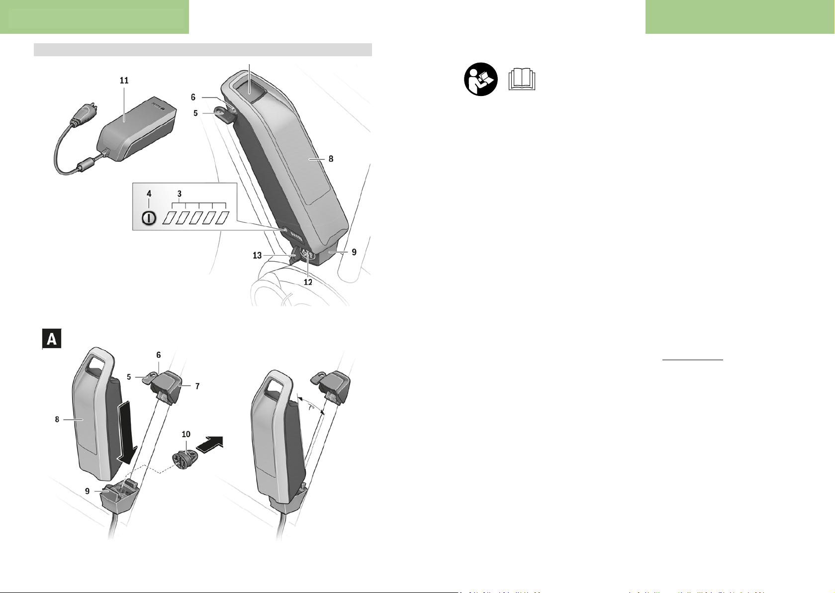
The numbering of the components shown refers to the illustrations on the graphics pages at the beginning of the
manual.
All representations of bicycle parts, apart from the batteries
and their holders, are schematic and may differ from those
on your own eBike.
In addition to the functions shown here, changes to software
relating to troubleshooting and functional enhancements
may be introduced at any time.
(1)
Rack-mounted battery holder
(2)
Rack-mounted battery
(3)
Operation/state of charge indicator
English – 1
4.1.3. Baery
32 33
Page 18
Bosch operang instrucons Bosch operang instrucons
English – 2
(4)
On/off button
(5)
Key for the battery lock
(6)
Battery lock
(7)
Upper standard battery holder
(8)
Standard battery
(9)
Lower standard battery holder
(10)
Cover (supplied only on eBikes with two battery
packs)
(11)
Charger
(12)
Socket for charging connector
(13)
Charging socket cover
(14)
PowerTube battery safety restraint
(15)
PowerTube battery
(16)
PowerTube battery safety hook
Technical data
Li-ion battery PowerPack 300 PowerPack 400 PowerPack 500 PowerTube
Product code BBS240 A)
B)
BBS245 A)
B)
BBR240 C)
B)
BBR245 B)
C)
BBS260
A)
BBS265
A)
BBR260
C)
BBR265
C)
BBS270
A)
BBS275
A)
BBR270
C)
BBR275
C)
BBP280 horizontal
BBP281 vertical
Rated voltage V = 36 36 36 36
Nominal capacity Ah 8.2 11 13.4 13.4
Energy Wh 300 400 500 500
Operating temperature °C –5...+40 –5...+40 –5...+40 –5...+40
Storage temperature °C –10...+60 –10...+60 –10...+60 –10...+60
Permitted charging temperat-
ure range
°C 0...+40 0...+40 0...+40 0...+40
Weight, approx. kg 2.5/2.6 2.5/2.6 2.6/2.7 2.8
Protection rating IP 54 (dust- and
splash-proof)
IP 54 (dust- and
splash-proof)
IP 54 (dust- and
splash-proof)
IP 54 (dust- and
splash-proof)
A)
Standard battery
B)
Cannot be used in combination with other batteries in systems with two batteries
C)
Rack-mounted battery
Fitting
u Ensure the battery is placed on clean surfaces only.
Avoid getting dirt, e.g. sand or soil, in the charging socket
and contacts in particular.
Testing the battery before using it for the first
time
Test the battery before charging it for the first time or using
it in your eBike.
To do this, press the on/off button (4) to switch the battery
on. If none of the LEDs on the battery charge indicator (3)
light up, the battery may be damaged.
If at least one (but not all) of the LEDs on the battery charge
indicator (3) lights up, the battery will need to be fully
charged before using it for the first time.
u Do not charge or use batteries if they are damaged.
Contact an authorised bicycle dealer.
Charging the battery
u Use only the charger included with your eBike or an
identical original Bosch charger. Only this charger is
compatible with your eBike's lithium-ion battery.
Note: The battery is supplied partially charged. To ensure
full battery capacity, fully charge the battery in the charger
before using it for the first time.
To charge the battery, read and follow the instructions in the
operating manual for the charger.
The battery can be charged at any state of charge. Interrupting the charging process does not damage the battery.
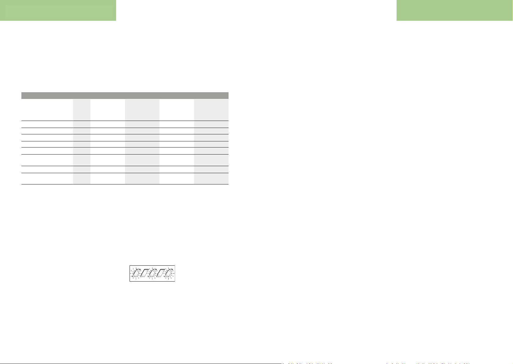
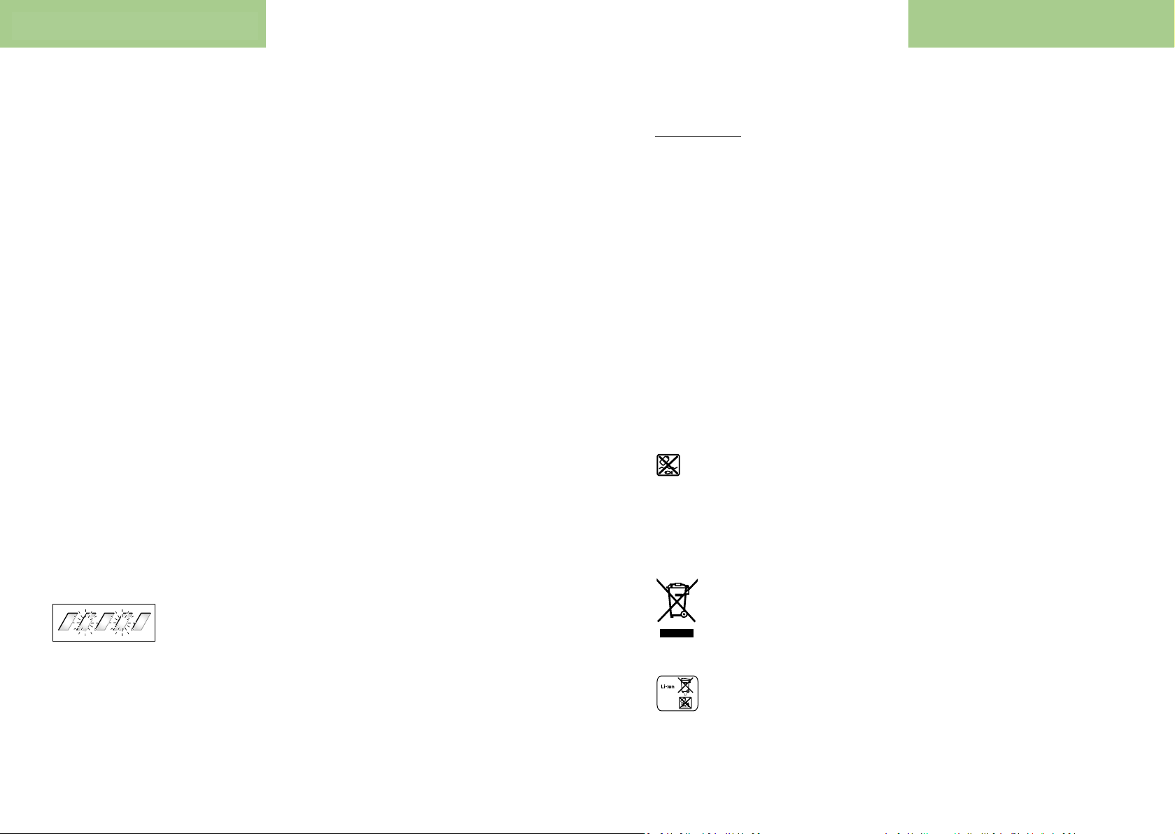
The battery has a temperature monitoring function which
only allows it to be charged within a temperature range of
0°C to 40°C.
If the temperature of the battery is outside this charging
range, three of the LEDs on
the battery charge indicator
(3) will flash. Disconnect the
battery from the charger and
let it acclimatise.
Do not reconnect the battery to the charger until it has
reached the correct charging temperature.
Battery charge indicator
The five green LEDs on the battery charge indicator (3) indicate the battery's state of charge of when the battery is
switched on.
Each LED represents approximately 20% of the charging capacity. When the battery is fully charged, all five LEDs will be
lit.
The battery's state of charge when switched on is also shown
on the display of the on-board computer. Read and follow
the instructions in the operating manuals for the drive unit
and on-board computer.
If the battery capacity is less than 5%, all the LEDs on the
battery charge indicator (3) on the battery will go out. The
display function of the on-board computer, however, will
carry on working.
Once charging is complete, disconnect the battery from the
charger and the charger from the mains.
Using two batteries for one eBike (optional)
The manufacturer can also equip an eBike with two batteries. In this case, one of the charging sockets will not be accessible or it will have been sealed with a sealing cap by the
bicycle manufacturer. Only charge the batteries via the charging socket that is accessible.
u
Never open charging sockets that have been sealed by
the manufacturer. Charging batteries via a charging
socket that used to be sealed may cause irreparable damage.
If you want to use an eBike that is designed for two batteries
with only one battery, cover the contacts of the unused
socket using the cover (10) provided. Otherwise there is a
risk that the exposed contacts will cause a short circuit (see
figures A and B).
Charging process for two batteries
If two batteries are fitted to an eBike, both batteries can be
charged using the uncovered connection. To begin with,
both batteries are charged one after the other until they
reach approx.80–90% capacity, then they are both charged
at the same time until full (the LED flashes on both batteries).
When the bike is in operation, power is drawn from both batteries on an alternating basis.
If you take the batteries out of the holders, you can charge
each one individually.
Charging with one battery fitted
If only one battery is fitted, you can only charge the battery
that has the accessible charging socket on the bike. You can
only charge the battery with the sealed charging socket if
you take the battery out of the holder.
Inserting and removing the battery
u
Always switch off the battery and the eBike system
when inserting the battery into the holder or removing it from the holder.
Inserting and removing the standard battery (see figure
A)
In order for the battery to be inserted, the key (5) must be
inserted into the lock (6) and the lock must be open.
To insert the standard battery (8), place it onto the contacts on the lower holder (9) on the eBike (the battery can
be titled towards the frame by up to 7°). Tilt it into the upper
holder (7) as far as possible until you hear it click into place.
Check that the battery is secure in all directions. Always secure the battery by closing the lock (6) – otherwise the lock
may open and the battery may fall out of the holder.
Always remove the key (5) from the lock (6) after closing it.
This prevents both the key from falling out and the battery
from being removed by unauthorised third parties when the
eBike is not in use.
To remove the standard battery (8), switch it off and open
the lock using the key (5). Tilt the battery out of the upper
holder (7) and pull it out of the lower holder (9).
Inserting and removing the rack-mounted battery (see
figureB)
In order for the battery to be inserted, the key (5) must be
inserted into the lock (6) and the lock must be open.
To insert the rack-mounted battery (2), slide it contactsfirst into the holder (1) on the rack until you hear it click into
place.
Check that the battery is secure in all directions. Always secure the battery by closing the lock (6) – otherwise the lock
may open and the battery may fall out of the holder.
Always remove the key (5) from the lock (6) after closing it.
This prevents both the key from falling out and the battery
from being removed by unauthorised third parties when the
eBike is not in use.
To remove the rack-mounted battery (2), switch it off and
open the lock using the key (5). Pull the battery out of the
holder (1).
Removing the PowerTube battery (see figureC)
❶
To remove the PowerTube battery, (15) open the lock
(6) using the key (5). The battery will be unlocked and
fall into the safety restraint (14).
❷ Press on the safety restraint from above. The battery
will be unlocked completely and fall into your hand.
Pull the battery out of the frame.
Note: As a result of varying designs, the battery may need
to be inserted and removed using a different method. In this
case, consult the bicycle documentation provided by your
bicycle manufacturer.
Inserting the PowerTube battery (see figure D)
In order for the battery to be inserted, the key (5) must be
inserted into the lock (6) and the lock must be open.
❶
To insert the PowerTube battery (15), place it so that
its contacts are in the lower holder of the frame.
❷ Push the battery upwards until it is held by the safety
restraint (14).
English – 3
34 35
Page 19
Bosch operang instrucons Bosch operang instrucons
English – 4
❸ Press the battery upwards until you hear it click into
place. Check that the battery is secure in all directions.
❹
Always secure the battery by closing the lock (6) –
otherwise the lock may open and the battery may fall
out of the holder.
Always remove the key (5) from the lock (6) after locking it.
This prevents both the key from falling out and the battery
from being removed by unauthorised third parties when the
eBike is not in use.
Operation
Start-up
u
Use only original Bosch batteries that the manufacturer has approved for your eBike. Using other batter-
ies can lead to injuries and pose a fire hazard. Bosch accepts no liability or warranty claims if other batteries are
used.
Switching on/off
Switching on the battery is one way to switch on the eBike
system. Read and follow the instructions in the operating
manuals for the drive unit and on-board computer.
Before switching on the battery, i.e. the eBike system, make
sure that the lock (6) is closed.
To switch on the battery, press the on/off button (4). The
LEDs on the indicator (3) will light up, indicating the battery's state of charge at the same time.
Note: If the battery capacity is less than 5%, none of the
LEDs on the battery charge indicator (3) will light up.
Whether the eBike system is switched on is only visible on
the on-board computer.
To switch off the battery, press the on/off button (4) again.
The LEDs on the indicator (3) go out. This will also switch
the eBike system off.
If no power is drawn from the eBike drive for about 10
minutes (e.g. because the eBike is not moving) and no button is pressed on the on-board computer or the operating
unit of the eBike, the eBike system, and therefore also the
battery, will switch off automatically to save energy.
The battery is protected against deep discharge, overloading, overheating and short-circuiting by the Electronic Cell
Protection (ECP). In the event of danger, a protective circuit
switches the battery off automatically.
If a fault is detected in the
battery, two of the LEDs on
the battery charge indicator
(3) will flash. Contact an authorised bicycle dealer if this
happens.
Recommendations for optimal handling of the
battery
The service life of the battery can be extended if it is looked
after well and especially if it is stored at the correct temperature.
As it ages, however, the capacity of the battery will diminish,
even with good care.
A significantly reduced operating time after charging indicates that the battery has deteriorated. You can replace the
battery.
Recharging the battery before and during storage
When you are not going to use the battery for an extended
period (longer than three months), store it at a state of
charge of around 30% to 60% (when two to three of the
LEDs on the battery charge indicator (3) are lit).
Check the state of charge after six months. If only one of the
LEDs on the battery charge indicator (3) is lit, charge the
battery back up to around 30% to 60%.
Note: If the battery is stored with no charge for an extended
period of time, it may become damaged despite the low selfdischarge and the battery capacity could be significantly reduced.
Leaving the battery permanently connected to the charger is
not recommended.
Storage conditions
If possible, store the battery in a dry, well-ventilated place.
Protect it against moisture and water. When the weather
conditions are bad, it is advisable to remove the battery from
the eBike and store it in a closed room until you use it next,
for example.
Store the eBike batteries in the following locations:
– In a room with a smoke alarm
– Away from combustible or easily flammable objects
– Away from heat sources
Store the batteries at temperatures between 0°C and
20°C. Never store them at temperatures below –10°C or
above 60°C. To ensure that the service life is as long as possible, storage at approx. 20°C (room temperature) is recommended.
Make sure that the maximum storage temperature is not exceeded. Do not leave the battery in your car in the summer,
for example, and store it away from direct sunlight.
Leaving the battery on the bicycle for storage is not recommended.
Maintenance and servicing
Maintenance and cleaning
u
The battery must not be submerged in water or
cleaned using a jet of water.
Keep the battery clean. Clean it carefully with a soft, damp
cloth.
Clean and lightly grease the connector pins occasionally.
Please contact an authorised bicycle dealer if the battery is
no longer working.
After-sales service and advice on using products
If you have any questions about the batteries, contact an authorised bicycle dealer.
u
Note down the key manufacturer and number on the
key (5). Contact an authorised bicycle dealer if you lose
the key. Give them the name of the key manufacturer and
the number on the key.
For contact details of authorised bicycle dealers, please visit
www.bosch-ebike.com
Transport
u
If you transport your eBike attached to the outside of
your car, e.g. on a bike rack, remove the on-board
computer and the eBike battery to avoid damaging
them.
The batteries are subject to legislation on the transport of
dangerous goods. Private users can transport undamaged
batteries by road without having to comply with additional
requirements.
When batteries are transported by commercial users or third
parties (e.g. air transport or forwarding agency), special requirements on packaging and labelling (e.g. ADR regulations) must be met. When preparing items for shipping, a
dangerous goods expert can be consulted as required.
Do not ship batteries if the housing is damaged. Apply tape
over exposed contacts and pack the battery such that it cannot move around inside the packaging. Inform your parcel
service that the package contains dangerous goods. Please
also observe any additional national regulations should these
exist.
If you have any questions about transporting the batteries,
contact an authorised bicycle dealer. You can also order suitable transport packaging from the dealer.
Disposal
Batteries, accessories and packaging should be
recycled in an environmentally friendly manner.
Do not dispose of batteries along with household waste.
Apply tape over the contact surfaces of the battery terminals
before disposing of batteries.
Do not touch severely damaged eBike batteries with your
bare hands – electrolyte may escape and cause skin irritation. Store the defective battery in a safe location outdoors.
Cover the terminals if necessary and inform your dealer.
They will help you to dispose of it properly.
In accordance with Directive 2012/19/EU
and Directive 2006/66/EC respectively, elec-
tronic devices that are no longer usable and de-
fective/drained batteries must be collected
separately and recycled in an environmentally
friendly manner.
Please return batteries that are no longer usable to an au-
thorised bicycle dealer.
Li-ion:
Please observe the information in the section
on (see "Transport", pageEnglish–5)
Subject to change without notice.
English – 5
36 37
Page 20
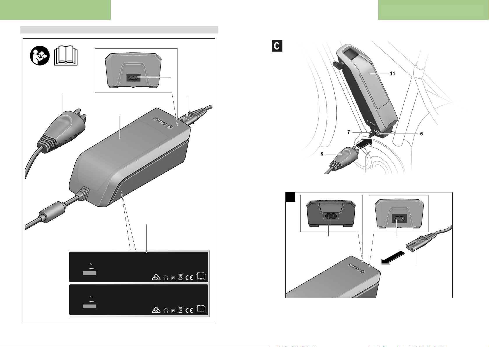
Bosch operang instrucons Bosch operang instrucons
2 |
eBike Battery Charger 36-6/230
0 275 007 918
Li-Ion
Use ONLY with BOSCH Li-Ion batteries
Input: 230V 50Hz 2.15A
Output: 36V 6A
Made in Vietnam
Robert Bosch GmbH, Reutlingen
Fast Charger BCS250
eBike Battery Charger 36-4/230
0 275 007 907
Li-Ion
Use ONLY with BOSCH Li-Ion batteries
Input: 230V 50Hz 1.5A
Output: 36V 4A
Made in PRC
Robert Bosch GmbH, Reutlingen
Standard Charger BCS220
Standard Charger
(2)
(3)
(1)
(5)
(4)
4 |
3
2
2
A
OBJ_BUCH-2031-005.book Page 4 Friday, April 1, 2016 12:24 PM
4.1.4. Baery charger
38 39
Page 21
Bosch operang instrucons Bosch operang instrucons
Safety instructions
Read and observe the safety warnings and directions
English – 1
English – 2
Technical data
u
fire and/or serious injury.
Save all safety warnings and instructions for future reference.
The term battery is used in these instructions to mean all
original Bosch eBike rechargeable battery packs.
Do not expose the charger to rain or wet
conditions. If water enters a charger, there is
a risk of electric shock.
u Charge only Bosch lithium-ion batteries that are ap-
proved for use in eBikes. The battery voltage must
match the battery charging voltage of the charger.
Otherwise there is a danger of fire and explosion.
u Keep the charger clean. Dirt poses a risk of electric
shock.
u Always check the charger, cable and plug before use.
Stop using the charger if you discover any damage. Do
not open the charger. Damaged chargers, cables and
plugs increase the risk of electric shock.
u Do not operate the charger on an easily ignited sur-
face (e.g. paper, textiles, etc.) or in a flammable environment. There is a risk of fire due to the charger heating
up during operation.
u Take care if you touch the charger while it is charging.
Wear protective gloves. The charger can get very hot,
especially when the ambient temperature is high.
u The battery may give off fumes if it becomes damaged
or is used incorrectly. Ensure the area is well ventilated and seek medical attention should you experience any adverse effects. The fumes may irritate the
respiratory system.
u Do not place the charger or the battery near flam-
mable materials. Ensure the battery is completely dry
and placed on a fireproof surface before charging.
There is a risk of fire due to the heat generated during
charging.
u The eBike battery must not be left unattended while
charging.
u Supervise children during use, cleaning and mainten-
ance. This will ensure that children do not play with the
charger.
u Children or persons who, owing to their physical,
sensory or mental limitations or to their lack of experience or knowledge, are not capable of safely operating the charger may only use this charger under supervision or after having been instructed by a responsible
person. Otherwise, there is a danger of operating errors
and injuries.
Read all the safety and
general instructions. Fail-
ure to observe the safety
and general instructions
may result in electric shock,
contained in all the eBike system operating instructions and in the operating instructions of your eBike.
u A sticker in English is adhered to the bottom of the char-
ger (marked (4) in the diagram on the graphics page).
This says: Use ONLY with BOSCH lithium-ion batteries.
Product description and
specifications
In addition to the functions shown here, changes to software
relating to troubleshooting and functional enhancements
may be introduced at any time.
Product features
The numbering of the components shown refers to the illustrations on the graphics pages at the beginning of the
manual.
Individual illustrations in these operating instructions may
differ slightly from the actual conditions depending on the
equipment of your eBike.
Charger
(1)
Device socket
(2)
Device connector
(3)
Charger safety instructions
(4)
Charging connector
(5)
Socket for charging connector
(6)
Charging socket cover
(7)
Rack-mounted battery
(8)
Operation/state of charge indicator
(9)
Battery on/off button
(10)
Standard battery
(11)
Charger Standard Charger
Product code BCS220 BCS230 BCS250
Rated voltage V ~ 207...264 90...264 207...264
Frequency Hz 47...63 47...63 47...63
Battery charging voltage V = 36 36 36
Charging current (max.) A 4 2 6
Charging time
– PowerPack 300, approx. hrs 2,5 5 2
– PowerPack 400, approx. hrs 3,5 6,5 2,5
– PowerPack 500, approx. hrs 4,5 7,5 3
Operating temperature °C 0 ...+40 0 ...+40 0 ...+40
Storage temperature °C –10 ...+50 –10 ...+50 –10 ...+50
Weight, approx. kg 0,8 0,6 1,0
Protection rating IP 40 IP 40 IP 40
A)
The charging current is limited to 4A for the PowerPack
300 and for Classic + Line batteries.
The specifications apply to a rated voltage [U] of 230 V. These specifications may vary at different voltages and in country-specific models.
(36–4/230)
Operation
Start-up
Connecting the charger to the mains (see figure A)
u Pay attention to the mains voltage. The voltage of the
power source must match the voltage specified on the
rating plate of the charger. Chargers marked 230 V can
also be operated at 220 V.
Plug the device connector (3) of the power cable into the
device socket (2) on the charger.
Connect the power cable (country-specific) to the mains.
Charging the removed battery (see figure B)
Switch the battery off and remove it from its holder on the
eBike. When doing so, read and observe the operating instructions of the battery.
u Ensure the battery is placed on clean surfaces only.
Avoid getting dirt, e.g. sand or soil, in the charging socket
and contacts in particular.
Plug the charging connector (5) of the charger into the
socket (6) on the battery.
Charging the battery on the bike (see figures C andD)
Switch the battery off. Clean the cover of the charging
socket (7). Avoid getting dirt, e.g. sand or soil, in the charging socket and contacts in particular. Lift the cover of the
charging socket (7) and plug the charging connector (5) into
the charging socket (6).
u Charge the battery only in accordance with all safety
instructions. If this is not possible, remove the battery
from the holder and charge it in a more suitable location.
Charging process for two batteries
If two batteries are fitted to an eBike, both batteries can be
charged using the uncovered connection. To begin with,
both batteries are charged one after the other until they
reach approx.80–90% capacity, then they are both
charged at the same time until full (the LED flashes on both
batteries).
When the bike is in operation, power is drawn from both batteries on an alternating basis.
If you take the batteries out of the holders, you can charge
each one individually.
Charging process
The charging process begins as soon as the charger is connected to the battery or charging socket on the bike and to
the mains.
Note: The charging process is only possible when the temperature of the eBike battery is within the permitted charging temperature range.
Note: The drive unit is deactivated during the charging process.
The battery can be charged with or without the on-board
computer. When charging without the on-board computer,
the charging progress can be observed via the battery
charge indicator.
When the on-board computer is connected, a charging notification appears on the display.
Compact Charger
(36–2/100-230)
When doing so, read and observe the operating instructions of the battery.
Fast Charger
(36–6/230)
A)
40 41
Page 22
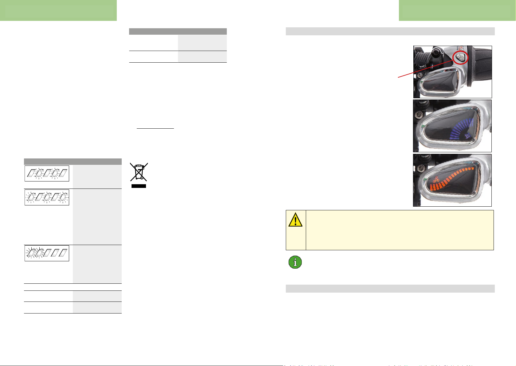
Bosch operang instrucons
The state of charge is displayed by the battery charge indicator (9) on the battery and by the bars on the on-board computer.
The LEDs on the battery charge indicator (9) will flash during
the charging process. Each solid illuminated LED represents
approximately 20% of the charging capacity. The flashing
LED indicates the next 20% currently charging.
Once the eBike battery is fully charged, the LEDs extinguish
immediately and the on-board computer is switched off. The
charging process is terminated. The state of charge can be
displayed for three seconds by pressing the on/off button
(10) on the eBike battery.
Disconnect the charger from the mains and the battery from
the charger.
When the battery is disconnected from the charger, the battery is automatically switched off.
Note: If you have charged the battery on the bike, carefully
close the charging socket (6) with the cover (7) after charging, so that no dirt or water can get in.
If the charger is not disconnected from the battery after
charging, the charger will switch itself back on after a few
hours, check the state of charge of the battery and begin the
charging process again if necessary.
Errors – causes and corrective measures
Cause Corrective measures
Battery defective
Two LEDs flash on the battery.
Contact an authorised bike
dealership.
Battery too warm or too cold
Three LEDs flash on the
battery.
Disconnect the battery from
the charger until the charging
temperature range has been
reached.
Do not reconnect the battery
to the charger until it has
reached the correct charging
temperature.
The charger is not charging.
No LEDs flashing (one or
more LEDs will remain permanently lit depending on
the state of charge of the
eBike battery).
Contact an authorised bike
dealership.
Charging not possible (no indicator on battery)
Connector not attached
properly
Check all connections.
Battery contacts dirty Carefully clean the battery
contacts.
Cause Corrective measures
Socket outlet, cable or charger defective
Check the mains voltage,
have the charger checked
over by a bike dealership.
Battery defective Contact an authorised bike
dealership.
Maintenance and servicing
Maintenance and cleaning
If the charger fails, please contact an authorised bike dealership.
After-sales service and advice on using products
If you have any questions about the charger, contact an authorised bike dealership.
For contact details of authorised bike dealerships, please
visit www.bosch-ebike.com
Disposal
Chargers, accessories and packaging should be recycled in
an environmentally friendly manner.
Do not dispose of chargers along with household waste.
Only for EU countries:
According to the European Directive 2012/19/
EU on Waste Electrical and Electronic Equipment and its implementation into national law,
chargers that are no longer usable must be collected separately and disposed of in an environmentally friendly manner.
Subject to change without notice.
English – 3
4.2. NuVinci Harmony gear hub
The twist grip on the Nuvinci Harmony actuates
a servo motor electronically on the rear wheel
42 43
hub which changes transmission rao of the hub.
Two operang modes are featured on the
NuVinci H8 twist grip and can be alternated
between using the Mode key:
Automac mode: blue display The cadence
which is to remain constant is determined with
the twist grip. Cadence is symbolised in blue on
the display. The transmission rao is adapted
automacally during travel.
Manual mode: orange display In this mode,
the twist grip determines the transmission rao.
This is symbolised on the display in orange.
If the Bosch system ceases assistance due to a at baery, a minimal
energy reserve remains available to the NuVinci Harmony for shiing
processes. This can be depleted within approx. 30 min., depending on
the number of shiing processes.
-> Shiing is thereaer no longer possible!
When at a stands ll, only 50 to 70% of the transmission range is
available on NuVinci hubs. The remaining range is only available while
riding.
4.3. Gates Carbon Drive Belt
When delivered, the belt exhibits opmum tension and does not have to be
retensioned, even aer prolonged use of the drive. Correctly mounted, the belt is
extremely resilient in the pulling direcon. The carbon bres embedded in the belt
are extremely exible, however, are also sensive to mistreatment as follows:
Operaon
Page 23
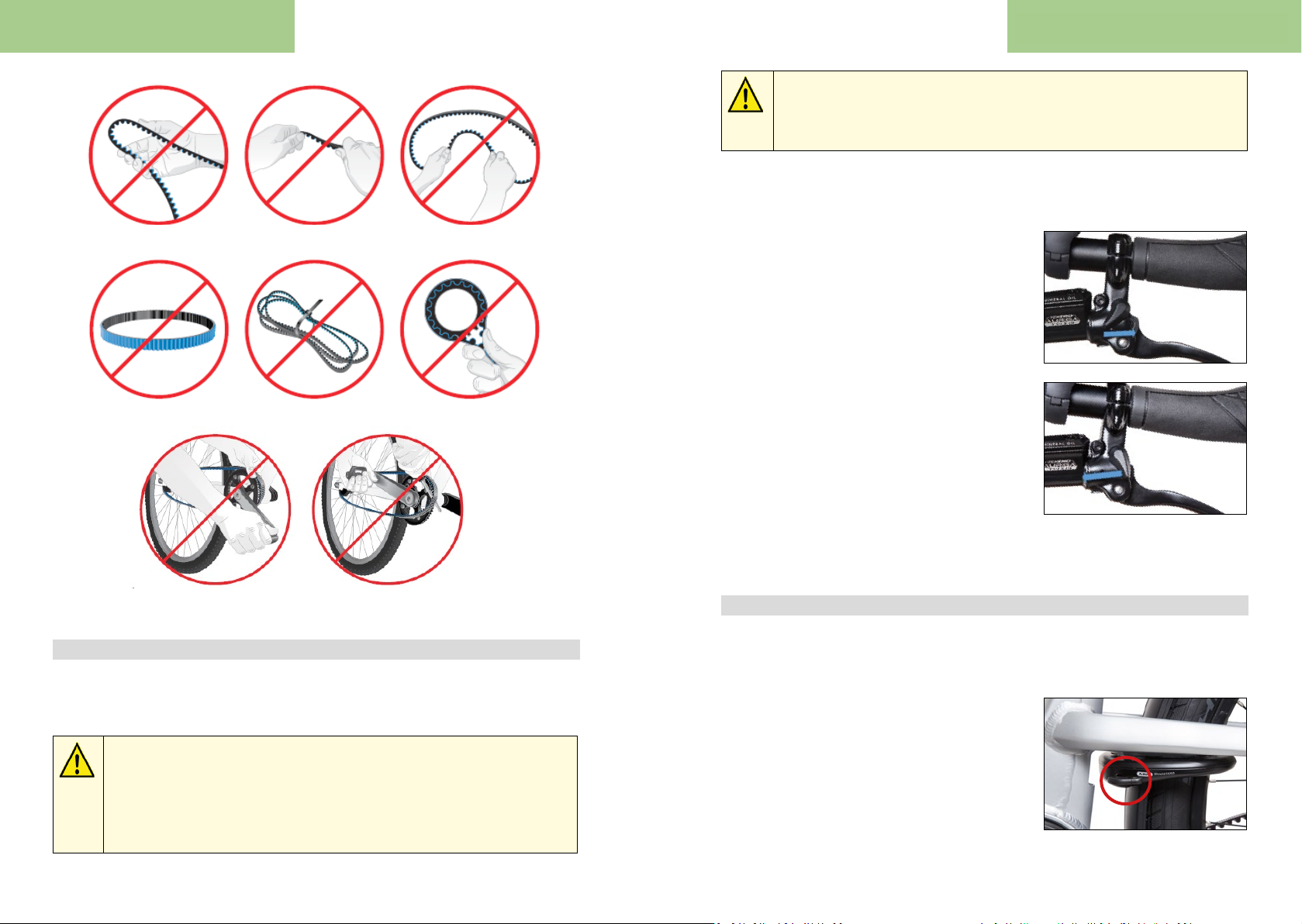
Operaon
Operaon
Brake discs and brake callipers can become extremely hot under braking,
in parcular following long descents.
-> Do not touch the brake system with your hands aer heavy braking.
You could suer burns.
Both brake levers feature a turning lever which can be used to block the respecve
brake.
Kinking Twisng Bending backwards
Turning upside down Binding together Being used as a strap spanner
Fing with the sprocket Fing with the lever
4.4. Brake system
Your ProCargo CT1 is equipped with hydraulic disc brakes. The le brake lever
acts simultaneously on both front wheel brakes, the right brake lever acts on the
rear brake.
In an unloaded condion, the axle load is minimal on the front wheels.
The wheels are blocked extremely quickly with heavy front braking.
Front wheels blocked in curves will lead to understeer, the bike slides
forwards in a direct line.
-> The rear brake should be predominantly applied in an unloaded
condion and the front brakes applied only tentavely.
For locking:
• Pull the brake lever towards the handlebar.
• At the same me, push the rotary
switch towards the end of the handlebar
unl the brake blocks.
To release the brake locking:
• Pull the brake lever towards the
handlebar
• At the same me, push the rotary
switch towards the stem unl the brake
lever retracts
The brake system compensates wear of the brake pads automa cally and ensures a
constant pressure point for the brake.
4.5. Frame lock on rear wheel
The ProCargo CT1 can be secured quickly and easily with the integrated frame lock.
The keys for frame lock and baery lock are the same.
The lock:
• Insert the key and turn in a clockwise
direc on. Hold in this posion.
• Push the halfring into the spokes
with the other hand using the lever on
the lock.
• Release the key and remove.
44 45
Page 24
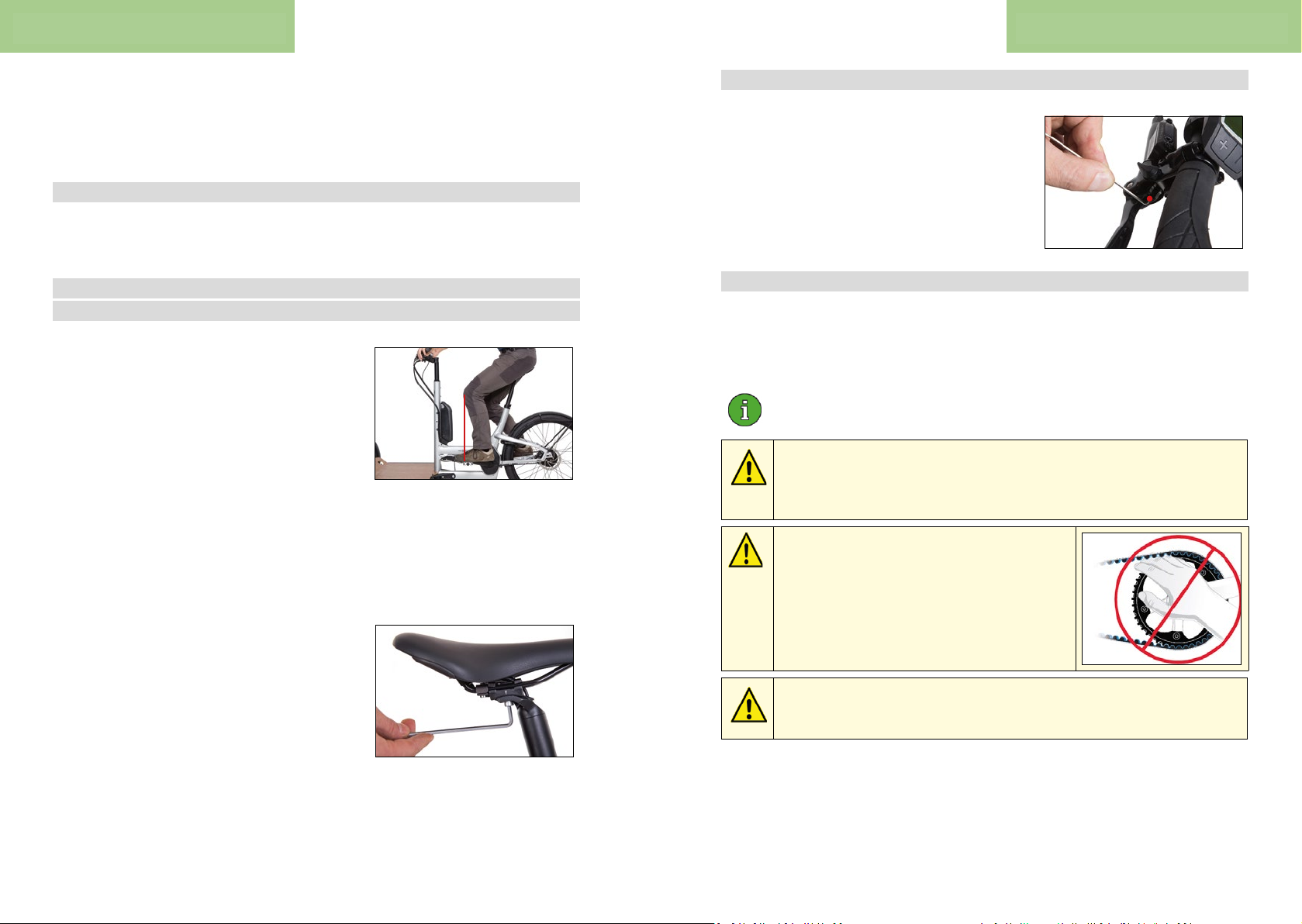
Ergonomic seng
Maintenance
To unlock the frame lock:
• Insert the key and turn in a clockwise direcon. The half-ring snaps back
automacally.
• Release the key and remove.
4.6. Pannier holders
The Wingee mudguards feature integrated side struts for the mounng of panniers.
Each side can carry a maximum load of 8 kg.
5. Ergonomic seng
5.1. Horizontal saddle posion and lt
The opmum horizontal saddle posion can be
determined using the „knee plumb line“.
The knee plumb line can be determined using a
weight suspended on a piece of string.
The knee plumb line should pass through the
pedal axle or just in front of it.
Sit on the pedelec in the posion shown above with horizontal crank arms and have
a second person determine the knee plumb line.
Ideally, the saddle is horizontally aligned with the upper side or with the saddle p
lted slightly forwards.
To adjust the saddle posion and lt, loosen the
two Allen screws of the saddle clamp situated
behind the seatpost under the saddle.
You can now shi the saddle in the guide of the
clamp and adjust the lt.
Then ghten both screws with 9-10 Nm.
5.2. Adjus ng grip distance of the brake lever
The grip distance can be adjusted using an Allen
key at the posi on marked in red.
The grip distance of the brake lever should be
adjusted so that it is possible to wrap the
foremost phalanges of 2-3 ngers behind the
brake lever.
6. Maintenance
Regular maintenance of the cargo bike will ensure that it remains safe and
funconal. Please observe the following informaon before every maintenance
measure.
Sormo oers a service concept. Get in touch with your direct Sormo
contact person or the Sortmio Service Team.
Maintenance requires technical skills. You are responsible for the
maintenance work being carried out correctly.
-> If you do not feel condent doing the work, have the bike serviced
by a dealer or contact the Sormo Service.
Risk of clamping and crushing if the maintenance work is carried out with the drive unit
switched on! Your hands could get stuck in
the moving drive between belt and socket.
-> Always remove the baery before commencing any maintenance work.
Risk of clamping and crushing when carrying out maintenance work.
Your ngers could get stuck between moving parts.
-> Pay aenon to your hands and work carefully.
46 47
Page 25
Maintenance Maintenance
6.1. List of wear parts
The following parts are subject to funcon-related wear which is not covered by
the warranty:
• Baery
• Tyres and tubes
• Brake pads, brake discs
• Belts and sockets
• Rubber seals and rings (e.g. in the NuVinci hub)
• All moving parts (e.g. bearings)
• Bowden cables, including mantel
• Hydraulic oil and lubricants
• Handlebar grips
• Paint and all surfaces (Examples: Cable outer mantels cause wear on
the paintwork / Actuaon of the foot pedal for lt blocking abrades the
paintwork in this area.)
If no further explanaon is given, the wear of these parts is due to fricon.
6.2. Recommended maintenance intervals
The need for maintenance of your pedelec depends on its use and leaves do not
specify themselves precisely. You should use the pedelec at least once a year Check
with a specialist dealer or wait for the Sormo Service Team to let.
As a guide, we suggest the following maintenance intervals:
Once aer 100-300 km:
• Check the ghtening torques of the grips, brake levers, saddle, seatpost,
stem, handlebar
• Check the spoke tension, if necessary true the wheel
Monthly (or every 500 km):
• Check wear condion of the brake pads
• Check wear condion of the tyres (tread and side wall)
• Check bearing clearance of headsets, hubs and pedals
• Ensure secure xing of crank arms
• Ensure secure seang of dust protecon on the track rod ends and
reghten as required
Yearly (or every 3000 km):
• Check complete brake system (including wear condi on of brake discs)
• Grease the pivot points of both brake levers
• Check the ghtening torques of the grips, brake levers, saddle, seatpost,
stem, handlebar
• Check wear condi on of the belt
• Check clearance of the track rod ends
• Inspect V-arms for cracks
• Check ghtening torque of „V-arms on frame“ screws. Nominal: 70 Nm
• Check ghtening torque of „tubes beneath loading area“ clamping
screws. Nominal: 14 Nm
6.3. Aer an accident
If parts of the drive unit (cable, motor, ba ery) are visibly damaged
due to an accident, there is a risk of electric shock. In this case, remove
the baery immediately.
Stop that Drive system from the Sormo Service Team or from a
specialist dealer check.
Parts of your ProCargo CT1 may be damaged due to an accident, which
can cause a risk of breakage.
-> Aer an accident, contact the Sormo Service Team or contact a dealer
for damaged parts such as the frame, suspension, handlebar, handlebar,
stem, seat post, crank and check pedals and replace if necessary.
6.4. Baery
The baery is a wear part as it ages over me (even if it is not used), and in
parcular with usage. Its service life is dependent upon the following factors:
During use, service life of the baery is primarily determined by the performance
requirements. Frequent use of high assistance levels reduces service life of the
baery.
48 49
Page 26
Maintenance Maintenance
During storage/non-use, the following factors are relevant for service life:
• Storage temperature. Opmum: 0-20 °C. Temperatures above 30°C or
parking the bike with the baery in direct sunlight reduces service
life of the baery.
• Charging status. Opmum charging status: 40-60% (=2-3 LEDs) Storing the
baery fully charged or completely at reduces the service life.
6.5. Tyers
Transporng cargo with the ProCargo CT1 will result in increased wear of the
tyres compared with a bicycle. Wear can be avoided on the side walls of the tyres
by ensuring sucient tyre pressure (refer to secon 3.1). Reduce wear to the
tyre treads by avoiding blocking of the tyres when braking.
You will need to replace your tyres if the rubber tread is so worn down that the
braid underneath is exposed, or if the tyres have become porous due to ageing and
frequent exposure to the sun.
6.6. Changing tyres/tubes
6.6.1. Front wheels
It is possible to replace the tyres on the mounted front wheels. Proceed as follows
in this regard:
Ensure that the respec ve wheel is raised o
the ground and is freely rotatable, whereby the
vehicle is supported beneath the loading area
on the corresponding side (e.g. using a beverage
crate). Alterna vely,the cargo bike may also be
lain on its side.
The long track rod beneath the loading area can bend if it is used to
support the ProCargo CT1.
-> Do not use the track rod to prop up the bike.
6.6.2. Removing the rear wheel
• Switch o the Bosch drive unit and remove the baery.
• Lock the front wheel brake.
• Prop up the vehicle under the motor rail,
using a beverage crate for example, so
that the rear wheel is raised completely
o the ground.
• Grip the connector on the ribbed
secon and pull it carefully forwards
from the hub interface.
• Loosen the axle nuts around a few full
turns on both sides.
• Li the rear wheel at the axle nuts and
pull the tab washers outwards on both
sides so that they are no longer gripping
into the dropout. (Belt tension does not
have to be relieved for removal)
• Pull the rear wheel downwards out of
the frame. The tab washers should thus
no longer be gripping into the dropouts.
• Remove the belt from the front socket
without twisng and then from the rear
socket.
The frame could become scratched if the cargo bike is lain on its side.
-> Lay a blanket, for example, down on the ground to protect the contact
points of the ProCargo CT1.
50 51
Page 27
Maintenance Maintenance
6.6.3. Changing the tyre/tube
• Unscrew the valve cap and large knurled nut from the valve.
• Release the air completely by applying pressure to the valve pin in the
centre of the valve.
• Use tyre levers to loosen the tyre on
one side of the rim. If necessary, use
water and detergent to facilitate liing
of the tyre.
• Remove the tyre and tube and imple-
ment the desired change.
• Lightly inate the tube (approx. diameter of 2 cm) and insert it into
the tyre.
• Insert the valve through the valve hole in the rim and pull the tyre and
tube combinaon from one side onto the rim.
• Observe the running direcon of the tyre imprinted by the manufacturer.
• Then lever the other side of the tyre onto the rim using tyre levers.
• Turn the knurled nut onto the valve unl it contacts the rim.
• Inate the tyre to the maximum pressure indicated on the tyre wall so that
the tyre sits evenly on the rim. A „plop“ sound is normal.
• Then lower the pressure to the desired value (refer to secon 3.1.).
• Screw the valve cap onto the valve
6.6.4. Fing the rear wheel
• Posion the rear wheel beneath the dropouts and, very carefully to begin
with, t the belt onto the rear socket without twisng.
• Li the belt onto the front socket without
twisng and place the rear wheel in the
frame dropouts. Ensure that the brake
disc slides between the brake pads.
• Now remove the spacer being used for support (e.g. the beverage crate) so
that the rear wheel is lowered down onto the ground.
• Check fastening of the tab washers. These should be seated securely in
the dropouts.
• Tighten the axle nuts with a ghtening torque of 30 to 40 Nm.
• Insert the connector at the NuVinci hub interface so that it clicks into place.
• At the same me, ensure that the arrow markers line up with one another.
6.7. Calibrang the NuVinci Harmon
It is imperave that the NuVinci Harmony is calibrated whenever
two acve orange bars are being indicated in the display of the Harmony
twist grip with the drive unit acvated.
If the NuVinci shi funcon is inconsistent or faulty, the NuVinci system may also
have to be calibrated.
Calibraon should be performed during a ride with the drive unit switched on,
however, with the assistance deacvated (o).
Proceed as follows for calibraon:
• Pedal with moderate force and maintain this throughout the enre
calibraon process.
• Hold the Mode key on the Harmony twist grip pressed unl the hub
begins the automac switching processes for calibraon aer 5-7 s.
Calibraon is indicated via a „to and fro moon“ bar in the display,
as well as noises of the servo motor at the rear. You can now release
the Mode key. Connue pedalling moderately.
• If the servo motor is no longer generang any noises and the display
indicator remains constant, calibraon is complete.
6.8. Brakes
Work on the hydraulic brake system should be carried out by the Sormo Service
Team or a specialist workshop. Observe the yearly inspecon (or every 3,000 km)
recommended for the brake system by a specialist dealer or by Sormo.
52 53
Page 28
Maintenance Cleaning and care
6.8.1. Wear of brake pads and brake discs
Brake pads and brake discs are subject to funconal wear caused by fricon
between the two parts. Heavier loads on the cargo bike will lead to increased
wear of both parts compared with a two-wheeled bike. Wear depends on
the riding style, terrain, weather and ground condions, meaning that no binding
infor maon can be given in this regard.
Brake discs must be replaced aer approx. 4 to 5 changes of brake pad pairs,
as they are made of a harder material. A regular inspecon of the brake pads is
recommended every 500 km.
6.8.2. Checking the brake pads
The brake pads must be replaced,
• when they are reduced to 2.5 mm thickness (height of carrier plate and
fricon lining)
• become contaminated with oil (leads to reduced braking power)
Check thickness of the brake pads as follows:
• First remove the circlip with pliers.
• Now replace the brake pads as required.
• Slide in the brake pads once again from above.
• Push the Allen screw through brake calliper and pads and ghten the
Allen screw with a ghtening torque of 3-5 Nm.
• Secure the screw with the circlip.
7. Cleaning and care
• If necessary, clean the ProCargo CT1 with water, a so sponge or a so
brush.
• The Gates Carbon Drive Belt is also cleaned with water and does not need
to be lubricated.
• The contacts of the baery and the baery holder on the frame can be
wiped with a damp cloth. Wait unl the contacts are dry before reaaching
the baery.
A high-speed jet of water, for example from a garden hose, can cause
damage to the bearings, NuVinci hub, Bosch ba ery, motor and display.
The manufacturer is not liable for these damages.
The presence of oil on the brake discs or brake pads diminishes
the braking ac on.
-> Avoid any contact from oil with the brake discs or pads!
• Unscrew the Allen screw to remove the
brake pads. Remove the brake pads from
above.
• Use a calliper gauge to check the brake
pad thickness
54 55
Page 29
Technical specicaons Technical specicaons
8. Technical specicaons
8.1. Comonent list
Motor Bosch Performance Line Cruise CX 25 km/h
Drive unit
Acceleraon
Brakes
Wheels
Human
interface
Baery Bosch PowerPack 500 Wh
On-board computer Bosch Purion
Gear shiing NuVinci N380 SE hub with Harmony H8 twist grip
Crank ISIS Miranda Delta 170 mm
Front Sprocket Gates CDX 24 T
Belt Gates Carbon Drive CDX 111 T
Rear Sprocket Gates Carbon Drive CDX 28 T
FW brakes Tektro Auriga Twin, 180 mm
RW brakes Tektro Auriga Tune, 180 mm
Front tyres Schwalbe Big Ben Plus 55-406
Rear tyres Schwalbe Super Moto-X 62-584
Rims Ryde Andra 40 36H, FR: 20", RR: 27.5"
Spokes Black stainless steel (2.34 - 2.0 mm)
Stem Satori Compact 2, 31.8 mm, 95 mm, adjustable angle
Handlebar Satori Noir, 31.8 mm, 630 mm, 15° backsweep
Grips Herrmans DD36
Seatpost Satori Camber 31.6 mm, 400 mm
Saddle Selle Royal Shadow Gel
Pedals VP 658
Mudguards Tubus Wingee
8.3. Tightening torque of screws
Part Torque/Nm
Bosch Purion on-board computer on handlebar 1
Handlebar grips 3
Brake pad locking screw 3 - 5
Brake discs (6x T25 screw) 4 - 6
Stem on steerer tube 5
Stem on handlebar 5 - 6
Brake levers (clamp on the handlebar) 5 - 7
Seatpost clamp 5 - 7
Brake calliper or adapter on fork or frame 6 - 8
Seatpost saddle clamp 9 - 10
"Pipes beneath loading area" clamping screws 14
Bosch chainring lockring 20 - 25
Pedals 30 - 35
Axle screws NuVinci hub 30 - 40
"V-arms on frame" screws 70
8.4. Frame number and nameplate
• The frame number is located on the front
side of the motor casing.
• The nameplate is located on the rear side of
the motor casing.
Safety
Headlight 2x Supernova E3 E-Bike V521s
Rear light Supernova E3 Tail Light 2
8.2. Weights
Baery weight 2.5 kg
Curb weight including baery approx. 46 kg
Permissible rider weight 100 kg
Permissible cargo on loading area 140 kg
56 57
Page 30
Liability for defects
EC Declaraon of Conformity
9. Liability for defects
In most European countries a 24-month warranty is spulated by law, beginning
on the day of purchase.
The original invoice must be submied for the defect liability claim.
You are entled to the warranty under the following condions:
• There is a manufacturing defect, material defect or informaon error.
• The damage referred to in the complaint was already present at the me
of delivery.
• The product was not altered due to funcon-related wear or ageing.
• The damage was not caused by violaon of the intended use.
• Baery: this exhibits a residual capacity of less than 60% of the nominal
capacity within two years (from the date of purchase) and a maximum
500 load cycles.
a charge cycle is complete charging of the baery with a single charge
or several paral charges (e.g. two half charges).
The warranty does not include:
• All wear parts according to the list of wear parts, unless they are
producon or material defects
• Damage caused by improper use
• Damage caused by failure to observe the procedures described in
the „Maintenance“ secon
• Damage caused by improper repair tools and insucient care
• Damage caused by the use of used parts
• Damage caused by subsequent mounng of non-standard equipment
and technical modicaons
10. EC Declaraon of Conformity
-Translation-
EC declaraon of conformity
HNF GmbH
Bahnhofstraße 150
16359 Biesenthal
HNF GmbH declares that the machine
Pro Cargo CT1
a Pedelec, meets all relevant provisions of Machinery Directive 2006/42/EC.
Furthermore, the machine complies with the following directive:
• Directive of Electromagnetic compatibility 2014/30/EC
The following other technical standards have been applied :
• DIN EN 15194:2017, Cycles - Electrically power assisted cycles - EPAC
• DIN EN ISO 4210: part 1-9, Cycles - Safety requirements for bicycles
• EDIN 79010:2017, Bicycles - Transportation bikes and Cargo Bikes
Document assignee: Joachim Osten, Bahnhofstraße 150, 16359 Biesenthal, Germany
HNF GmbH
Biesenthal,
19.07.2018
__________________________ _____________________________
Kalle Nicolai / CTO Benjamin Börries / CEO
58 59
Page 31
Disposal
Notes
11. Disposal
This symbol on your vehicle indicates that, in accordance
with the WEEE Direc ve (2012/19/EU; Waste Electrical
and Electronic Equipment Direc ve), the Baeries
Direcve (2006/66/EC) and na onal laws implemenng
these Direcves, the product may not be disposed of with
household waste.
Please take the pedelec to a local collec on point at the end of its service life.
Packaging materials must be separated by type and disposed of according to local
regula ons. You may return the ba ery to an e-bike retailer or send it to Sormo
for disposal in the supplied hazardous goods box:
Sormo Internaonal GmbH
Dreilindenstraße 5
86441 Zusmarshausen
Service
The Sormo team is at your side with help and advice:
Tel. +49 8291 850-499
Tel. +49 800 7678466
Fax. +49 800 7678499
E-Mail direct@sormo.de
1. INSPECTION
Date
Stamp / Signature of the dealer
3. INSPECTION
2. INSPECTION
Date
Stamp / Signature of the dealer
4. INSPECTION
Date
Stamp / Signature of the dealer
5. INSPECTION
Date
Stamp / Signature of the dealer
Date
Stamp / Signature of the dealer
6. INSPECTION
Date
Stamp / Signature of the dealer
60 61
Page 32

Notes Notes
7. INSPECTION
Date
Stamp / Signature of the dealer
9. INSPECTION
Date
Stamp / Signature of the dealer
11. INSPECTION
8. INSPECTION
Date
Stamp / Signature of the dealer
10. INSPECTION
Date
Stamp / Signature of the dealer
12. INSPECTION
15. INSPECTION
Date
Stamp / Signature of the dealer
17. INSPECTION
Date
Stamp / Signature of the dealer
19. INSPECTION
16. INSPECTION
Date
Stamp / Signature of the dealer
18. INSPECTION
Date
Stamp / Signature of the dealer
20. INSPECTION
Date
Stamp / Signature of the dealer
13. INSPECTION
Date
Stamp / Signature of the dealer
Date
Stamp / Signature of the dealer
14. INSPECTION
Date
Stamp / Signature of the dealer
Date
Stamp / Signature of the dealer
21. INSPECTION
Date
Stamp / Signature of the dealer
Date
Stamp / Signature of the dealer
22. INSPECTION
Date
Stamp / Signature of the dealer
62 63
Page 33

 Loading...