

Page 1

Service Record Loop
SORG
Loop
ENG
SORG
2019-08-15
Service Record
In the following all individual adjustments of the wheelchair are
described. These adjustments require tools and specialised
knowledge. Please leave the adjustments to a qualied rehab
consultant.
Service Record Loop
SORG
Besondere Menschen, besondere Lösungen.
Unique people, unique solutions.
1 of 44
Page 2

Imprint
SORG Rollstuhltechnik GmbH+Co.KG
Benzstraße 3-5
68794 Oberhausen-Rheinhausen / Germany
Tel. +49 7254-9279-0
Fax +49 7254-9279-10
E-Mail info@sorgrollstuhltechnik.de
Web www.sorgrollstuhltechnik.de
Revision status
2019-08-15
Technical status
Technical changes and misprints reserved. The
pictures in this Instructions for use can dier
from the actual equipment components. However, a corresponding conduction is possible.
Copyright
All texts, pictures and graphics underlie copyright protection. All rights, including copying, publishing, editing and translating,
remain reserved. © by SORG Rollstuhltechnik GmbH+Co. KG Benzstraße 3-5, 68794
Oberhausen-Rhein hausen / Germany.
Our terms and conditions can be found
on our order forms and at www.sorgrollstuhltechnik.de/impressum.
2 of 44
Service Record Loop
SORG
2019-08-15
Page 3

Table of content
1 Seat shell base frame overview 5
2 General information 6
2.1 General indications 6
2.2 Documentation indications 6
2.3 Required torques and tools 6
2.4 Explanation of symbols 7
2.5 General safety instructions 8
3 Assembly Group 9
3.1 Assembly Group Wheels 9
3.1.1 Position rear wheel 9
3.1.2 Displacing the wheels without a
camber adapter (20",22",24") 9
3.1.3 Displacing the wheels with a
camber adapter (20",22",24") 10
3.1.4 12"/16" wheels 10
3.1.5 Camber 11
3.1.6 Wheel base extension for 20" + 22" 12
3.1.7 Casters 13
3.2 Assembly Group Frame 14
3.2.1 Frame arch for closed frames 14
3.2.2 Widening the frame 15
3.2.3 Additional crossbar 16
3.3 Assembly Group Seat 17
3.3.1 Adjusting the tilting direction 17
3.3.2
Displacing the seat plate horizontally
18
3.3.3 Displacing the seat plate vertically 19
3.3.4 Position wedge adapter 19
3.3.5 Release lever-seat wedge 20
3.3.6 Position push bar 20
3.3.7 Double gas spring 21
3.4 Assembly Group Back 25
3.4.1 Setting back depth 25
3.4.2 Setting height of the push bar 25
3.4.3 Setting back angle 25
3.4.4 Adjustment of back guide 26
3.4.5 Conversion from back angle
setting to back angle adjustment 27
3.4.6 Changing the basic setting of the
push height 27
3.5 Assembly Group Leg Supports 28
3.5.1 Positioning the leg supports 28
3.5.2 Leg supports: standard or angle
adjustable 29
3.5.3
Leg supports which swing to the side
30
3.5.4 Leg support can be elevated with
a physiological turning point 31
3.5.5 Multidirectional leg support 33
3.6 Assembly Group Brakes 34
3.6.1 Trum brake 34
3.6.2 Knee lever brake 36
3.7 Assembly Group Frame 37
3.7.1 Anti-tipper 37
3.7.2 Tipping lever 37
3.7.3 Outdoor Front End 38
4 Repairs and maintenance 39
4.1 Repairs 39
4.2 Spare parts 39
4.3 Maintenance 39
4.4 Disinfection 39
4.5 Storage 39
4.6 Reinstatement 40
4.7 Disposal 40
4.8 Maintenance/ Inspection 40
5 Technical specications 42
5.1 Data and measurements 42
5.2 Meaning of labels 43
5.3 Declaration of conformity 43
2019-08-15
Service Record Loop
SORG
3 of 44
Page 4

4 of 44
Service Record Loop
SORG
2019-08-15
Page 5

1 Seat shell base frame overview
2
1
15
14
3
5
4
6
1 push handle
2 eccentric tensioner for angle adjustment of
the push handle
3 gas pressure spring
4 handle for height adjustment of the
push handle
5 wheel cover
6 wedge and wedge adapter
7 brake lever
8 caster housing
9 caster fork
10 caster
11 Foot plate
7
12 rear wheel
13 handrim
14 anti-tipper
8
15 axle plate
9
10
1213
16 17 18
11
19
20
21
22
23
16 push handle
17 release lever for seat tilt
18 control lever for drum brake
19 rccentric tensioner for angle adjustment of
the push handle
20 control lever for angle adjustment of the
back
21 gas pressure spring to adjust the back angle
22 wheel cover
23 handrim
24 brake pressure pin of the cable brake
25 bar to widen the frame
26 foot plate
2019-08-15
24
2526
Service Record Loop
SORG
5 of 44
Page 6

2 General information
2.1 General indications
In the following all individual settings, adjustments and repairs as well as the yearly inspection of
the wheelchair are described. These adjustments require tools and specialised knowledge. Ple-
ase leave the adjustments to a qualied rehab consultant.
Should questions or suggestions come up then please contact your medical supply store or our
team (+49 7254 9279-0).
2.2 Documentation indications
Please note:
• Information about before sale can be found in the instructions for use
• Infomation for the user can be found in the instructions for use
• For maintenance instructions see: Chapter 4 (Repair & Maintenance)
2.3 Required torques and tools
For the following screws needed torque:
• M5: 5 Nm;
• M6: 7 Nm;
• M6 (axle plate) 10 Nm
• M8: 20 Nm;
• M10 (nut): 25 Nm; (caster)
• quick release axle tting 40 Nm
Needed tools:
• torque wrench (5-50 Nm)
• open end wrench
• ex ratchet handle with socket wrench inserts
• hexagon screw driver
• Phillips screw driver
• at head screw driver
• plastic mallet
• side cutter
• threadlocker (uid)
• bicycle inner tube repair kit
• work bench/jaw vise with rubber pads
6 of 44
Service Record Loop
SORG
2019-08-15
Page 7
2 General information
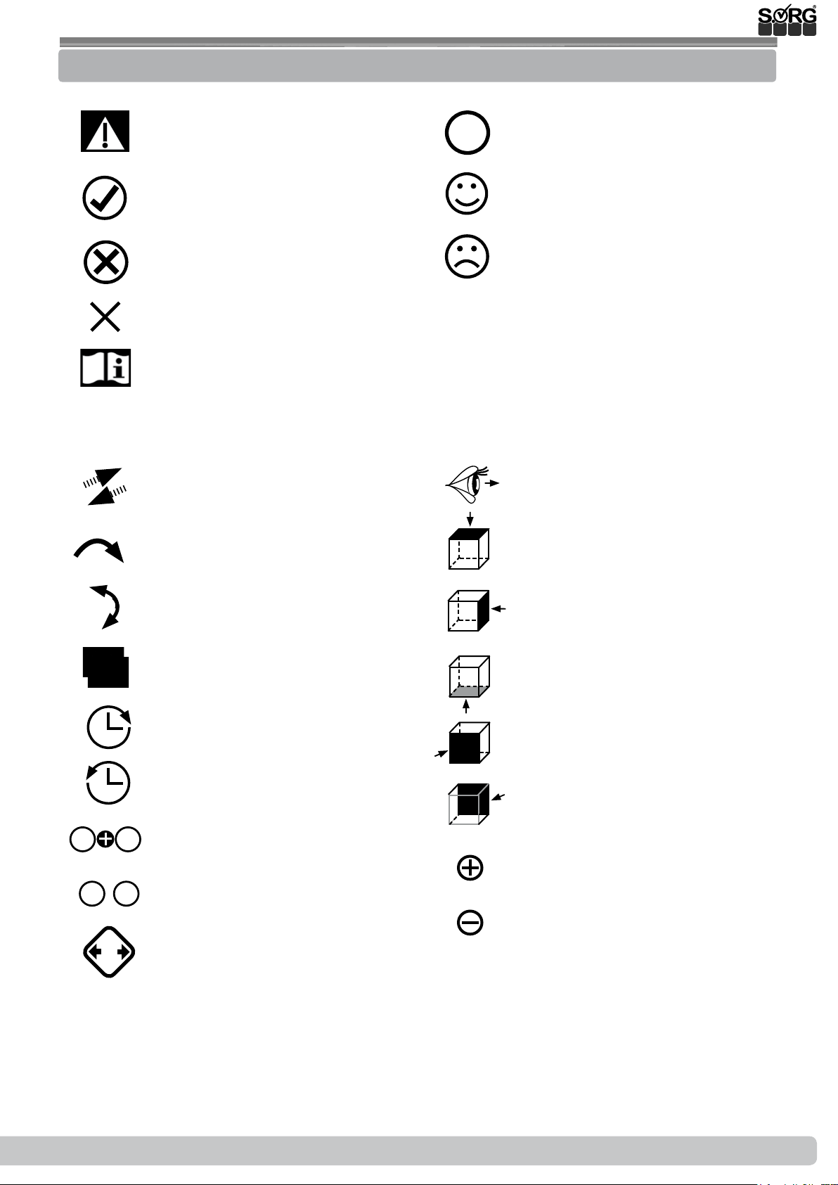
2.4 Explanation of symbols
Use
ATTENTION! Warnings for perso-
nal Safety aspects that are of the
utmost importance.
CORRECT safety adjustment/ use
WRONG adjustment/ use
NOT ALLOWED
References to additional/conti-
nuing reading.
push/ pull/ insert / move/
(A); (B)
important detail
correct or proper use/setting
incorrect or improper use/setting
reference from text to detail
point of view
1. 1.
2.
1.
;
2x
Push in specic direction
Setting or adjusting the angle
open/ close
Turn clockwise
Turn counter-clockwise
steps to be done at the same
time
steps to be done after each other
steps to be done on both sides
view from top
view from the side
view from the bottom
view from the front
view from the back
fasten parts
remove parts
2019-08-15
Service Record Loop
SORG
7 of 44
Page 8

2 General information
2.5 General safety instructions
Before each use be sure to check:
• frame, back tubes, attachments and accessories for visible damage, bends, cracks or missing/loose scews,
• wheels/quick release axles for rm t,
• sucient tire pressure, tire tread,
• functionality of the brakes,
• rm t of the angle adjustment elements/ eccentric clamps,
• rm t of the seat plate/ the back/ the foot plate,
• functionality of the anti-tipper/ seat and back straps,
• if all previously disassembled parts are re-inserted or rmly locked.
There is a risk of injuries (e. g. such as bruising) on all rotating or folding parts, including
adjustments, repairs and transport.
All wheelchair parts are to be handled with care. Do not throw or drop removable parts.
Before repairs or adjustments are made, clean/didinfect the wheelchair and secure it from
tipping over and/or falling down.
Only use original spare parts.
Safety nuts may only be used once. Lossened safety nuts must be replaced by new ones.
Only the regular maintenance of all safety-relevant parts on the wheelchair by a qualied
rehab workshop protects against damage and maintains our manufacturer's warranty.
Combination with products from other manufacturers
The wheelchair may only be combined with the electrical auxiliary drives apporved by the
manufacturer. Restrictions or adaptations as well as the attachment itself must be done by the
supplier of the additional system or the authorized specialist dealer.
Please check the conditions with the manufacturerer of the audiliary drives.
In combination of wheelchair and electric auxiliary drive, certain strains can occur which
can lead to damage to the wheelchair. Slowly approach obstacles and carefully overcome
them so that little force is applied to the caster, driving wheel and wheelchair as a whole.
8 of 44
Service Record Loop
SORG
2019-08-15
Page 9

3.1 Assembly Group Wheels
3.1.1 Position rear wheel
Check the tilt stability of Loop while fully tilted and with the patient, after alle positioning
adjustments of the rear wheels have been made and, if necessary, modify the position.
(1)We mount:
• 24” wheels in row (A),
• 22” wheels in row (B),
• 20” wheels in row (C),
• the adapters for 12”/16” wheels are
mounted in row (D).
Position 1 is the most passive (most stable), position 5 is the most active (most wobbly). The
wheels are factory-set in position 2. In this position, you receive a horizontal frame position
with corresponding caster. Other constellations
are possible. The horizontal frame position can
be reached through the adjustment of the casters.
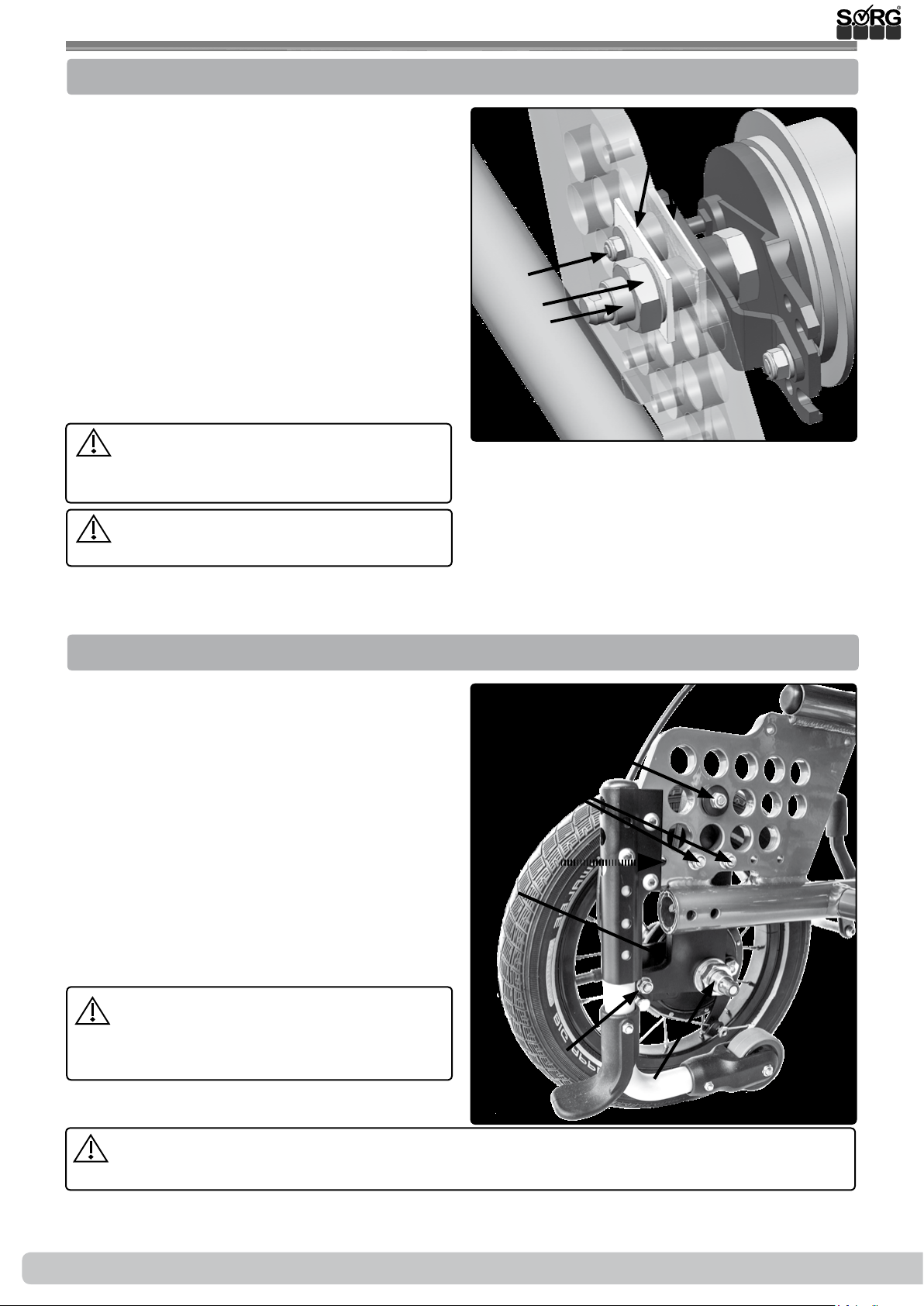
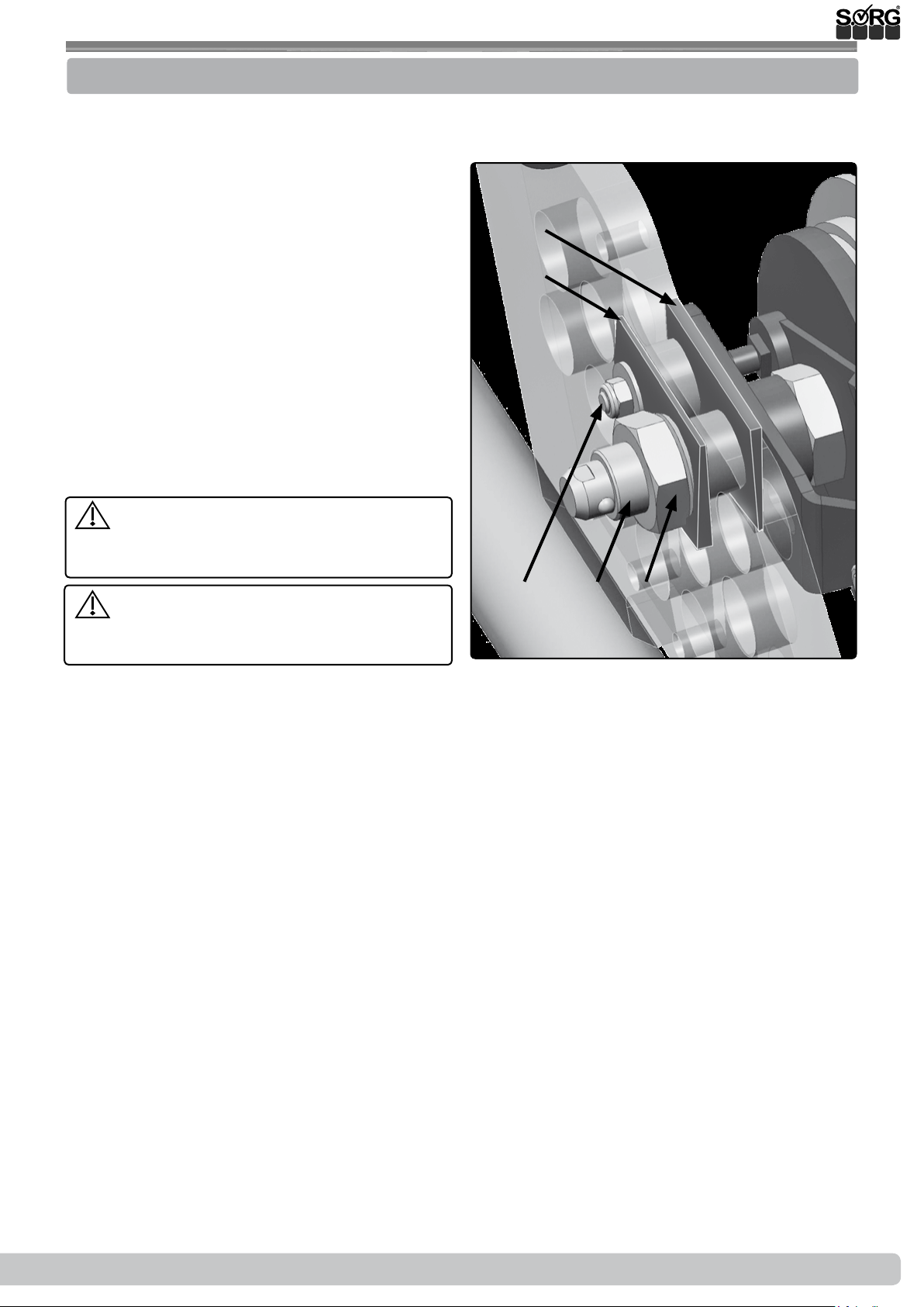
3.1.2 Displacing the wheels without a camber adapter (20",22",24")
• (2) Remove the wheels,
• remove the hexagon nut (A) of the
quick-release axle tting (B),
• place the tting (B) in the new hole,
• put the hexagon nut (A) back on, tighten
it and
• place the wheels back on.
(1)
1 2 3 4 5
(A)
(B)
(C)
(D)
(2)
(A)
(B)
Correct the position of the knee lever
brake and be sure that it functions properly.
2019-08-15
Service Record Loop
SORG
9 of 44
Page 10
3.1 Assembly Group Wheels
3.1.3 Displacing the wheels with a camber adapter (20",22",24")
• (1) Remove the wheels,
• remove the hexagon nut (A) of the
quick-release axle tting (B),
• remove the nut (C) from the brake arm
(D) including the inner shell,
• remove both camber adapters (E) and
place them in front of the new position.
• Fixate both camber adapters (E) with the
tting (B) and the shell in the new posi-
tion,
• replace the hexagon nut (A) and tighten
it,
• replace and tighten the nut (C) from the
spacer.
The Camber adapters must always be
mounted opposite. At 0°: inner surface=
thick end facing up.
Correct the position of the knee lever
and be sure that it functions properly.
(1)
(E)
(C)
(A)
(B)
(D)
3.1.4 12"/16" wheels
Changing to 12”/16” wheels subsequently:
• (2) Remove the big wheels including the
brake pad, tting and drum brake arm,
• mount the adapter (A) for the 12”/16”
wheels with the screws (B) in the bottom
hole row (C)
• mount the screw (D) with the delivered
discs in the proper hole.
• Mount the quick-release axle tting (E)
with the brake pad and the drum brake
arm (F) analogously as described above
and
• put the 12”/16” wheels on.
Be sure that the drum brake functions
properly and if necessary establish its functionality (see drum brake).
(2)
(D)
(B)
(C)
(A)
(F)
(E)
Whe using a knee lever brake, this must be displaced (see knee lever brake). Correct the
position and be sure that if functions properly.
To change the camber to 0°, please proceed as described.
10 of 44
Service Record Loop
SORG
2019-08-15
Page 11
3.1 Assembly Group Wheels
3.1.5 Camber
To change the camber with a wheel base extension, please proceed as described here.
Changing the camber subsequently:
• (2) remove the rear wheels,
• remove the hexagon nut (A) of the
quick-release axle tting (B),
• remove the nut (C) from the drum brake
arm including the inner surface shell.
• Place both camber adaptors (D+E) in
front of the position wanted: (D) thick
end down; (E) thick end up-
• Fixate both with the tting (B) and the
shell from the drum brake spacer in the
new position,
• replace the hexagon nut (A) and tighten
it,
• replace the nut (C) of the drum brake
arm and tighten it.
Be sure that the drum brake functions
properly and if necessary, establish its functionality (see drum brake).
Correct the position of the knee lever
brake an be sure that it functions properly
(see knee lever brake).
(2)
(E)
(D)
(B)
(A)(C)
2019-08-15
Service Record Loop
SORG
11 of 44
Page 12

3.1 Assembly Group Wheels
3.1.6 Wheel base extension for 20" + 22"
To prepare the extension of the wheelbase:
remove the wheels completely on both sides
incl. brake body, tting etc.
remove the wheel guard completely,
if necessary remove the anti-tipper completely.
To extend the wheelbase
• (1) mount the wheelbase extension (A)
and the connecting plate (B) with the
screws (C),
• Mount the quick-release axle tting (D)
in the corresponding hole and
• Adjust the drum brake counterholder
(E) in the corresponding hole.
To move the clothes guard:
• (1) Move the clothes guard (F) back
and secure it with the corresponding
screws (G).
To adjust the clothing protection:
• (2) Replace the wheels and adjust the
clothes guard on the existing holes (A)
and slots (B).
(1)
(2)
(G)
(C)
(A)
(E)
(F)
(D)
(B)
(A)
To move the knee lever brake:
• (3) Replace the standard brake adapter
with the brake adapter for wheelbase
extensions (A).
• Adjust the knee lever brakes (B)
Check the functionality of the drum bra-
ke and restore it if necessary.
Correct the position of the knee lever
brake and then check its functionality.
To change the camber to 0 ° please proceed as
described there.
(3)
(B)
(B)
(A)
12 of 44
Service Record Loop
SORG
2019-08-15
Page 13
3.1 Assembly Group Wheels
3.1.7 Casters
If you would like to add a frame arch so that the
frame is closed in the front and more resilient:
• (2) Remove the caster adapters from
both sides (A) including the half shells
(B),
• put the frame arch (C) on and attach it
from the top with the screws (D),
• move the caster adapters (A) out of
the old holes (E+F) into the new holes
(F+G),
• mount the adapters (A) including half
shells (B) with the screws (H) in the new
position and adjust as described above
the casters in an absolute vertical position.
Correct the position of the knee lever
brake and be sure that if functions properly
(see knee lever brake)
After every change made on the casters
the steering head tendency must be newly
adjusted.
(1)
(A)
(C)
(B)
2019-08-15
Service Record Loop
SORG
13 of 44
Page 14
3.2 Assembly Group Frame
3.2.1 Frame arch for closed frames
For retrotting the frame bow for a frame
closed at the front, proceed as follows on both
sides of the frame:
• (1) Remove on both sides the steering
wheel adapter (3A) incl. Half-shells
(3B),
• if necessary, remove the knee lever
brakes
• and remove the caps at the end of the
frame tubes (A) and (B).
• (2) Secure the supplied sleeve (C) with
the screw (D) in the hole (E) provided.
• Insert the frame into the bottom frame
tube (C) with the bottom frame tube
(F).
• Screw the frame bow at the top with the
(G) screw to the sleeve (C).
• Check the tightness of the ttings
(D+G).
• (3) Move the steering wheel adapters
(A) and half shells (B) from the old
holes (E+F) into the new holes (F+G),
• Mount the adapters (A) of the halfshells (B) with the screws (H) in the new
position (F+G)
• and adjust as described
• Possibly. you must re-assemble and
adjust the toggle brakes
(1)
(2)
(A) (B)
(G)
(C)(D)(E)
(F)
Every change made on the seat and/ or
the tilting, the tilt behavior of the Loop must
be newly tested and practiced with a passenger and the help of an experienced and
strong person.
(3)
(H)
(E)
(F)
(G)
(B)
(A)
14 of 44
Service Record Loop
SORG
2019-08-15
Page 15
3.2 Assembly Group Frame
3.2.2 Widening the frame
To widen the frame:
• (1+2) remove both wheels,
• remove the screwing (A) from the crossbars (B) completely on one side,
• (2) remove the screwing (C) from the
seat board including the shell (D) completely.
• Displace both crossbars (1B) in the necessary size along the prepared holes on
the crossbar adapters 1 or 2 cm by putting the screws (1A) loosely back in.
• Place one or two shells (2E) on the outer
side (1 shell=1 cm, 2 shells=2 cm),
• place the screwing (2C) back through
the shell.
• Tighten all screw connections (1A and
2C).
• Precede the same with the screw connections (1A and 2C) on the other side.
Please regard the next chapter if your Loop
has an additional crossbar.
SORG
(1)
(C)
(A)
(C)
(B)
(2)
Both crossbars must be displaced in the
same distance on both sides. An asymmetrical assembly is dangerous and not allowed.
(E)
(D)
2019-08-15
Service Record Loop
SORG
15 of 44
Page 16

3.2 Assembly Group Frame
3.2.3 Additional crossbar
To xate the additional crossbar under the seat:
• (1) remove both wheels,
• then remove the screw connections,
completely on one side, of the bottom
crossbar as described above,
• on the same side, remove the screw connections (A) for the seat board,
• place the crossbar adapter (B) for the
top crossbar (C) in and screw it onto the
frame pipe with the screw (D).
• Place the top crossbar (C) in the wanted
hole of the crossbar adapter (B),
• with the screws (E), screw them together
in the same hole as the bottom crossbar,
• place or displace the shells from the seat
screwing (A) as described above,
• put the screws (A) back into the seat
board and tighten them rmly.
• Precede the same way on the opposite
side.
(1)
(D)
(B)
(A)
(C)
(E)
The crossbars must be displaced in the
same distance on both sides. An asymmetrical assembly is dangerous and not allowed.
16 of 44
Service Record Loop
SORG
2019-08-15
Page 17

3.3 Assembly Group Seat
3.3.1 Adjusting the tilting direction
(1) The tilting direction is determined by the
position of the gas spring at the bottom of the
carrier (A) and on top on the holders under
the seat board (B) as well as by the horizontal
(C) and vertical (D) position of the seat.
We mount standardly as follows:
For tilting from -5° to +35°:
• (2) with frame size 1 and 2,
• (3) with frame size 3.
For tilting from +2,5° to +40°:
• (4) with frame size 1 and 2,
• (5) with frame size 3.
After every change made on the seat
and/ or the tilting, the tilt behaviour of the
Loop must be newly tested and practised
with a passenger and the help of an experienced and strong person.
(1)
(C)
(B)
(D)
(A)
(2) (3)
(4) (5)
2019-08-15
Service Record Loop
SORG
17 of 44
Page 18
3.3 Assembly Group Seat
3.3.2 Displacing the seat plate horizontally
In order to displace the seat plate by 2 cm with
the same tilting direction (only possible with
frame sizes 2 and 3):
• (1) remove the screws (A) from the seat
plate (B) on both sides including the inner shells completely.
• (2) Remove the screws (F and D) from
the gas spring (E) completely,
• move the seat plate (1B) to the alternative position,
• replace the shells,
• replace the screws (1A) through the shell
• and retighten the screw connections
(1A).
• Place the gas spring (2E) in the alternative position (2F and 2D),
• replace the screw
• and tighten it.
After every change made on the seat
and/ or the tilting, the tilt behaviour of the
loop must be newly tested and practised
with a passenger and the help of an experienced and strong person.
(1)
(B)
(2)
(A)
(C)
(D)(F)
(E)
If the Loop
then please precede the same.
SORG
equipped with two gas springs
18 of 44
Service Record Loop
SORG
2019-08-15
Page 19

3.3 Assembly Group Seat
3.3.3 Displacing the seat plate vertically
In order to displace the seat plate by 2 cm with
the same tilting direction:
• (3) loosen both screws (C) from the
guide clip on both sides and
• remove both screws from the screw con-
nection (A) of the seat unit including the
half shells (B) on both sides completely.
• (4) Remove the screw connections of the
gas spring (F) including the shells completely.
• (3) Move the seat unit with the carriers
(D) to the desired measurements in the
holes (E) (each hole is ± 2 cm),
• (4) Displace the gas spring in the holes
(G) (each hole is ± 2 cm) in the same
measurement.
• Place the screws (3A) with the half shells
(3B) in the new position and tighten
them rmly.
• Place the screws (4F) with the shells in
the connection of the gas spring and
tighten them rmly.
(1)
(2)
(D)
(C)
(A)
(E)
(B)
After every change made on the seat
and/or the tilting, the tilt behaviour of the
loop must be newly tested and practised
with a passanger and the help of an experienced and strong person.
If you do not displace the seat unit and
the gas spring parallel, a dierent tilting
direction and a dierent seat adjustment will
result.
3.3.4 Position wedge adapter
You can adjust the seat position as described
in the chapter before, horizontally and vertically through the seat plate. In addition, you can
change the position of the wedge adapter.
In order to change the position of the wedge
adapter:
• (3) loosen all four screws (A),
• push the wedge in the wanted position
• and retighten all four screws (A).
(G)
(F)
(3)
(A)
and/ or the tilting, the tilt behaviour of the
loop must be newly tested and practised
with a passanger and the help of an experienced and strong person.
2019-08-15
After every change made on the seat
Service Record Loop
SORG
19 of 44
Page 20

3.3 Assembly Group Seat
3.3.5 Release lever-seat wedge
(1) The red release lever (A) of the wedge
adapter should stick out of the seat plate
about 1 cm.
To change the position:
• (2) loosen both screws (B),
• guide the release lever in the wanted position and
• retighten the screws (B).
With certain tilt adjustments “collisions” between gas spring and release lever can occur.
In this case, be sure that the gas spring has
enough room when the max. tilt angle is in use;
see chapter tilting
3.3.6 Position push bar
If, for example, you have a great structure depth
of the seat shell on the back, the structure depth
can be compensated through the position of
the push handles.
For this:
• (2) loosen the four screws (A) of the
push bar adapter (B),
• push the ends of the pipes from the
push bar in the wanted position, forward
or backward
• and retighten all four screws (A).
(2)
(2)
(A)
(B)
(C)
(B)
After, it is important that you check the
tilt behaviour of the loop with full strain
(with a passanger) and the help of an experienced and strong person.
If necessary, the centre of gravity must be
changed (wheelbase extension) and the positon of the anti-tipper must be renewed.
~ 1 cm
(A)
20 of 44
Service Record Loop
SORG
2019-08-15
Page 21
3.3 Assembly Group Seat
3.3.7 Double gas spring
The components involved:
(1) (A) seat plate
(B) top adapter for gas spring
(C) top mounting points for gas spring
(D) bottom adapter for gas spring
(E) bottom mounting points for gas spring
(F) release lever for gas spring
(G) Bowden cables (with release lever
on the push bar)
(H) gas spring
(I) frame traverse
(J) frame half
An oversight of the individual steps to apply a
second gas spring in short form:
1. Remove control lever of the gas spring
and wedge adapter,
2. move the already available gas spring,
3. take o frame half,
4. attach new gas spring adapter,
5. put frame back together,
6. mount the top adapter under the seat
plate,
7. attach new gas spring to the top adapter,
8. attach new gas spring to the bottom
adapter,
9. mount the release lever for the double
gas spring on the bar,
10. determine the max. length of the new
Bowden cable and install it, cut the
Bowden cables,
11. bring the back of the Loop into an upright position,
12. mount the Bowden cable on the respective release mechanism of both gas
springs,
13. xate the traction of the release mech-
anisms,
14. if necessary, retighten wedge adapter,
15. test the tilting with max. strain and if
necessary, adjust.
(1)
(G)
(B)
(C)
(H)
(I)
(A)
(J)
(E)
2019-08-15
(I)
(F)
Service Record Loop
(D)
SORG
21 of 44
Page 22

3.3 Assembly Group Seat
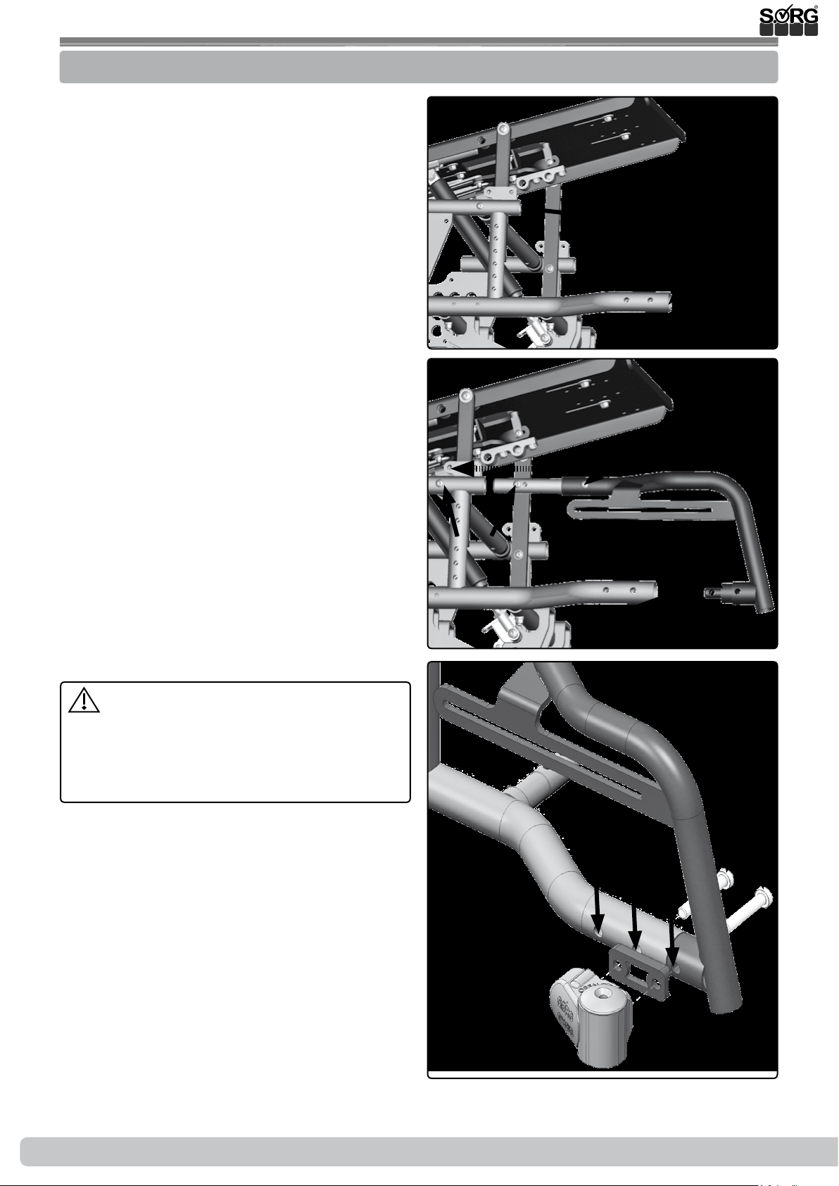
Step 1: control lever
• (1) Remove both screws (A) from the
control lever and the spiral cable shell
from the Bowden cables and
• remove the control lever of the seat
wedge under the seat plate.
Step 2: moving the gas spring
• (2) Loosen the four screws (A) and
• adjust the wedge adaptor so that the
front of the three screws (B) of the top
adapter is visible through the mount
hole (C).
• With the screws (B), remove the top
adapter of the gas spring.
With frame size 1, there are only the back two
screws (B), where in this case you do not have
to remove the wedge adapter.
• (3) Remove both screws (A).
• Displace the adapter (B) including gas
spring (C) in the alternative holes (D).
• (4) Displace the top adapter (A) in the
alternative holes (B) and xate the gas
spring back in the top adapter with the
screw (C) as in the same mounting point
as before.
• (5) Remove the inner cable of the
Bowden cable (A) on the release mechanism of the gas spring by loosening the
clamp (B) and the adjusting screw (C)
and/or the lock nut (D) and remove the
complete Bowden cable (A).
Step 3: removing half of the frame
• Remove one half of the frame as described in chapter before
(2)
(B)
(3)
(4)
(C)
(5)
(C)
(A)
(C)
(A)
(D)
(B)
(A)
(D)
(B)
(B)
(C)
(A)(C) (D) (B)
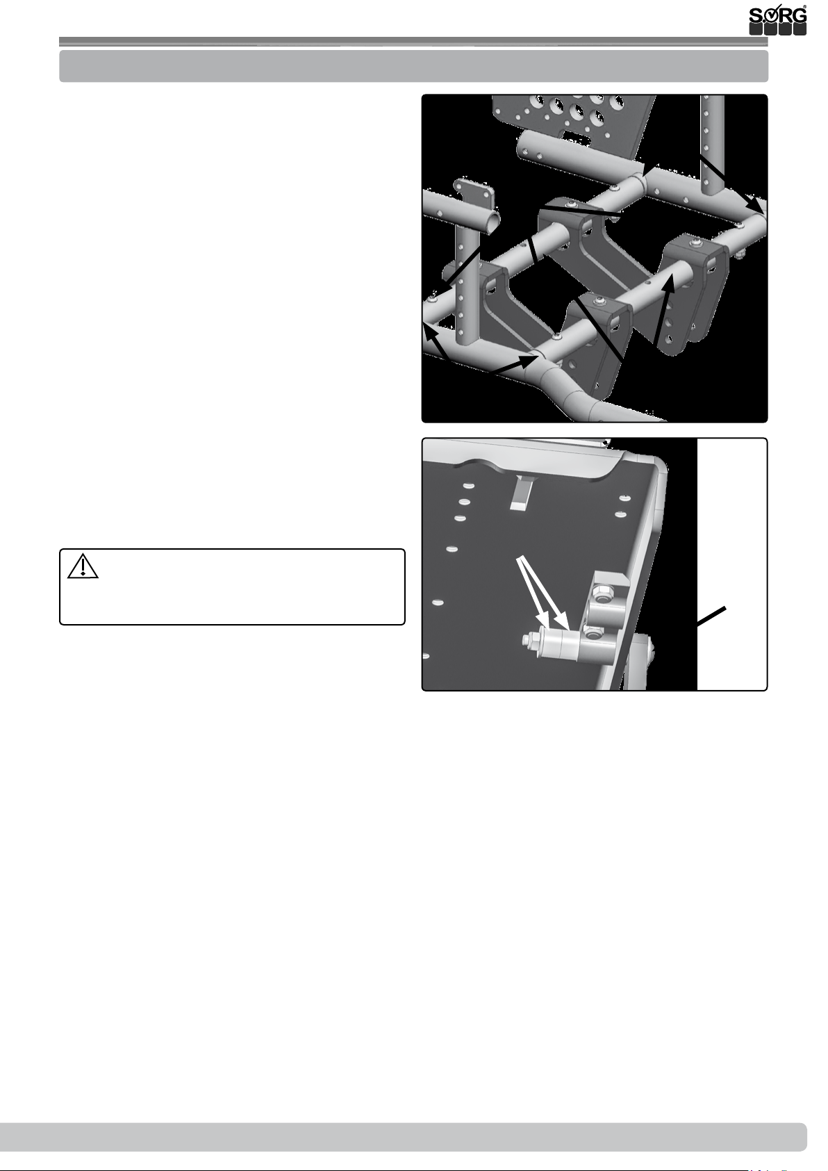
Step 4: applying the new adapter
• (6) Guide the second adapter (A) of
the gas spring on the traverses (B) and
connect the adapter with the screws (C)
tightly in the prepared holes of the traverses (see also picture 3D).
(1)
22 of 44
(A)
(6)
(C)
(B)
Service Record Loop
SORG
(C)
(A)(A)
2019-08-15
Page 23

3.3 Assembly Group Seat
Step 5: putting the frame together
• Screw the frame (as described in chapter
before) on the traverses back together.
Be sure to check that the traverse adapters are
put on symmetrical (right and left side in the
same hole!).
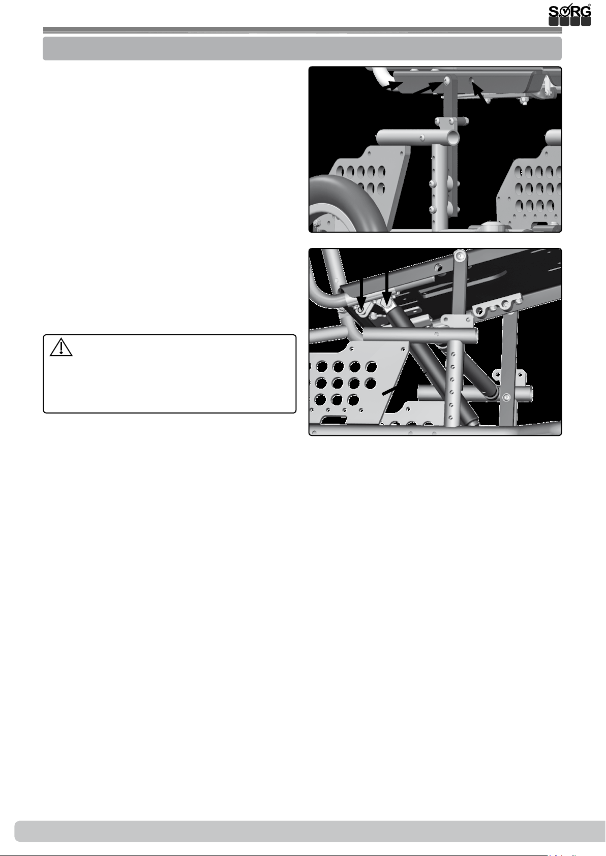
Step 6: mounting the top adapter
• (1) Both alternative mounting possibilities of the gas spring are shown in picture 1.
• Attach the second top adapter (A) of
the gas spring by screwing it on with the
three screws (B) underneath the seat
plate in the prepared holes.
Step 7: mounting the new gas spring on the top
• (1) Screw the gas spring on to the top
adapter (A) with the screw (C).
(1)
(A)
(A)
(C)
(B)
(C)
(2)
Step 8: mounting the new gas spring on the
bottom
• (2) Both alternative mounting possibilities of the gas spring are also shown in
picture 2.
• Screw the gas spring in the bottom
adapter with the screw (A) in the prepared holes (B).
Both gas springs must be mounted in the same
mounting points of the adapter.
Use the same mounting point as before. Oth-
erwise you will receive a dierent tilt direction.
For comparison: see chapter tilting.
Step 9: attaching the control lever again
• Mount the new control lever for the gas
spring on the push bar as described in
step 1 and
• (3) mount the control lever of the seat
wedge with both screws (A) under the
seat plate.
(B)
(3)
(A)
(B)
(A)
(A)
2019-08-15
Service Record Loop
SORG
23 of 44
Page 24

3.3 Assembly Group Seat
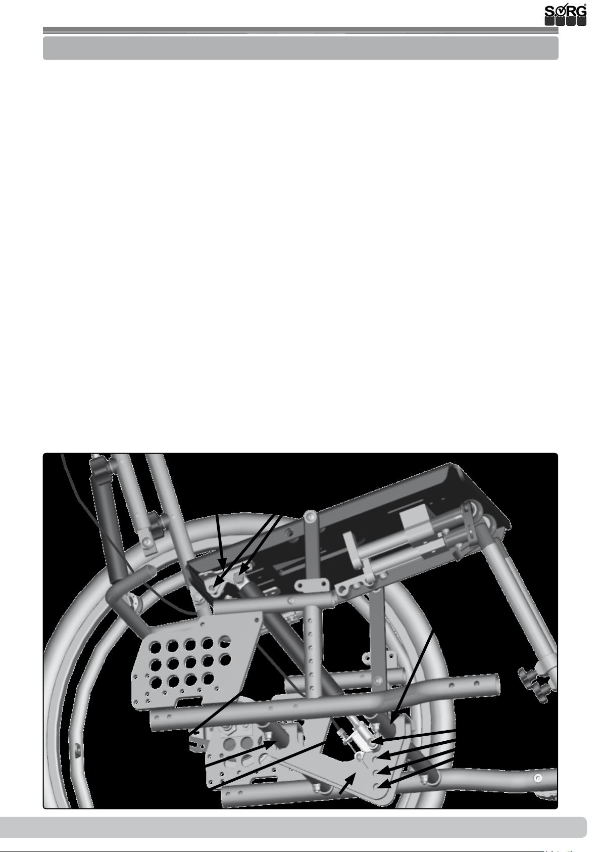
Step 10: installing the maximum length of the
Bowden cables
• Place the push bar in the maximum push
height,
• (1) fold the back of the Loop forward
and
• lie the push bar forward toward leg
support (see picture), so that maximum
length for the Bowden cables is reached.
• Now guide the new Bowden cable from
the release lever over the seat to the
back and then back to the front underneath the Loop to each release lever of
the gas springs.
• Fold the back of the Loop back in an upright position and
• cut the ends of both Bowden cables to
the needed measurements.
Step 11:
• (1) Fold the back of the Loop back in an
upright position.
Step 12: mounting the Bowden cables
• (2) Mount the ends (A) of both inner
cables on the release mechanism of the
gas spring.
• Guide the inner cables (B) rst through
the adjusting screw (C), then through
the hole (D) of the clamp (E).
• With a thumb, push the release lever
(A) slightly upward toward the adjusting
screw (C).
• While pushing the adjusting screw up,
tighten the clamp (D) by turning it.
• (3) Shorten the excess piece of Bowden
cable (A) just far enough so that you can
adjust the release moment, if necessary,
with the clamp.
(1)
(2)
(3)
(4)
(C)
(B) (C)
(B)
(D)
(E)
(A)
(A)
(A)
Step 13:
Step 14:
Step 15:
24 of 44
• Be sure that the release mechanism
functions properly and adjust the release
moment with the adjusting screw (3B)
and the lock nut (3C).
• Replace the back upright.
• (4) Push the wedge adapter back in the
wanted position and retighten the four
screws (A) for xating the wedge adapter.
Service Record Loop
After every change made on the seat
and/or the tilting, the tilt behavior of the
Loop must be newly tested and practiced
with a passanger and the help of an experienced and strong person.
SORG
2019-08-15
Page 25

3.4 Assembly Group Back
3.4.1 Setting back depth
To xate the back depth see chapter 2.3.6 Position push bar.
Tilt stability (see there)
3.4.2 Setting height of the push bar
The basic setting of the height adjustable push
bar can be changed as follows:
• (1) Remove both star knob screws (A)
from the bush bar,
• push the push bar up or down in the
guide slots (B) until the alternative hole
(C) is visible.
• There, place the star knob screws (A) in
and tighten them.
3.4.3 Setting back angle
If you have a seat shell with a xed back angle
you can adjust the back angle of the Loop to it
as follows:
• (2) place the seat shell with the wedge
on the wedge adapter and be sure that
the shell snaps in tightly.
• Remove both screws (A),
• bring the back of the Loop and the back
of the seat shell in a parallel position,
• xate this position by placing both screws
(A) in the alternative holes (B) and
• retighten the screws (A).
(1)
(C)
(2)
(C)
(B)
(A)
(B)
(A)
2019-08-15
Service Record Loop
SORG
25 of 44
Page 26

3.4 Assembly Group Back
3.4.4 Adjustment of back guide
(1) To add the back guide:
• place the clamping part (A) including
the connection part (B) on the traverse
(C) of the back pipes,
• place the back pipes of the Loop as close
as needed to the back of the seat shell.
To change the distance between shell and back
you have three options:
1. Displace the back of the Loop (see chapter position push bar),
2. displace the wedge adapter (see
chapter position wedge adapter),
3. displace the wedge under your seat
shell.
• After, mark the four holes (D) of the
connection part with a marker (also on
the opposite side, here not visible),
• remove the seat shell out of the wedge
adapter
• place the holes on the back of the seat
shell and in that, screw the connection
part (B).
(1)
(E)
(C)
(D)
(A)
(E)
(B)
Put the seat shell in and test if the lock element is tight in the connection part and if
necessary correct it with the four screws (E)
of both runners (F).
26 of 44
Service Record Loop
SORG
2019-08-15
Page 27

3.4 Assembly Group Back
3.4.5 Conversion from back angle setting to back angle adjustment
If you want to convert the seat shell from an
angle setting (1) to and angle adjustment (2),
then proceed as follows:
• (1) Remove the screws (A),
• remove the lock element (B) and
• remove the old angle setting element
(C).
• (2) Place the gas spring (A) at the bot-
tom in the adapter (B) and lock it with
the lock element (C),
• push the release lever (D) of the gas
spring (A) and adjust the length of the
piston rod (E) to where the connection
ts in the adapter (F),
• replace the screws (G),
• now let go of the release lever (D) and
tighten the screw (G).
(1)
(2)
(D)
(A)
(C)
(C)
(A)
(B)
(G)
(F)
(E)
(B)
3.4.6 Changing the basic setting of the push height
Ex works, the push bar is mounted in the lowest
setting.
(3) Here, the back pipes are shown transparent so that you can see the holes in the section
tube.
To change the height up to 10 cm higher:
• Remove the star knob screws (A) on both
sides completely (including half shells),
• push the push bar so far up until the two
holes (C) are visible guide slots (B) at
the bottom end of the section tube,
• place the star knob screws (A) (including
half shells) in both of these holes (B) and
retighten them.
(3)
(B)
(A)
(C)
2019-08-15
Service Record Loop
SORG
27 of 44
Page 28

3.5 Assembly Group Leg Supports
Leg supports with a divided footres are not suitable for users with tone dysregulation.
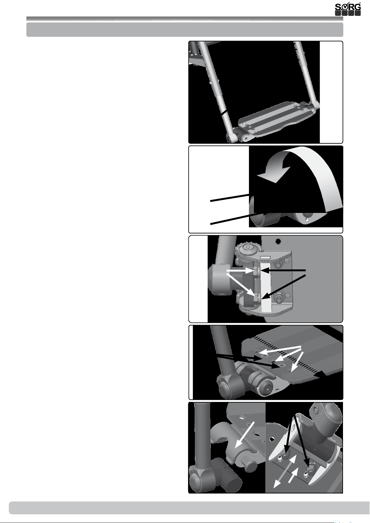
3.5.1 Positioning the leg supports
All leg supports are mounted under the seat plate, which is shown transparent here. You have two
scenarios available with which you can adjust the distance of the adapter to the seat shell.
1. Displacing the leg support adapter:
• (1) If necessary, you must move the
wedge adapter (here displayed transparent), so that through the mounting holes
(A) the holes underneath (2A) between
adapter (2B) and seat plate are accessible.
• Remove all four screws (B) and
• move the wedge adapter as stated
above.
• (2) Remove the screwing (A) between
adapter (B) and seat plate on both sides,
• move the adapter (B) along the drilled
holes (C) (= per hole about 2 cm),
• replace the screwing (A) back through
the seat plate and retighten the screws.
• Correct the position of the wedge adapter and
• screw it back on to the seat plate tightly.
(1)
(2)
(A)
(B)
(B)
(C)
(B)
(A)
(A)
(C)
2. Displacing the leg support in the adapter:
• (3) Loosen both screws (B) on the leg
support adapter (A) and slide the leg
support bars in the desired position.
• Retighten both screws (B).
• (4) When it comes to the leg supports
which swing to the side, loosen the
headless screw (A)
• push the leg support bars (B) in the desired position and
• retighten both screws (A).
• (5) So that the top end of the leg support bars (A) is stabilized under the footrest, two square tubes (B) are mounted
under the seat plate.
(5) The end of the leg support bar must always
overlap the stabilizing tube at least 1 cm.
After every change on the leg support be
sure to make sure that the casters can freely turn 360° by maximum tilting. If necessary,
make corrections on the casters or on the leg
support.
(3)
(C) (C)
(A)
(B)
(4)
(A) (B)
(5)
min. 1 cm
(B)
28 of 44
Service Record Loop
SORG
(A)
2019-08-15
Page 29

3.5 Assembly Group Leg Supports
3.5.2 Leg supports: standard or angle adjustable
Setting distance between footrest and seat
board
The distance between top edge of the seat
board and the top edge of the footrest can be
adjusted in the same way by standard leg supports (1) continuous or divided and angle adjustable leg supports (2) continuous or divided:
• (3) Remove both screws (A),
• remove the footrest/s and
• move the footrest/s along the holes (B)
in the new position/s.
• Replace both screws (A) and tighten
them.
When it comes to a continuous footrest you
must move both connections of the footrest
parallel on the leg support.
Setting the stop angle of the footrest/s
(4) With both adjusting screws you can adjust
the stop angle of the footrest/s.
• Flip the footrest/s back,
• loosen the lock nut (A)
• turn both adjusting screws (B) until you
have reached the wanted angle,
• retighten the lock nut (A).
(1)
(3)
Distance between
upper edge of seat
plate and upper
edge of foot plate
(B)
(2)
Distance between
upper edge of seat
plate and upper
edge of foot plate
(A)
Both adjusting screws must t close to
the tubes (C) when the footrest/s is/are in
use. Avoid an uneven tting position of the
adjusting screws.
(4)
(A)
(B)
(C)
2019-08-15
Service Record Loop
SORG
29 of 44
Page 30
3.5 Assembly Group Leg Supports
3.5.3 Leg supports which swing to the side
Setting distance between footrest and seat
plate
• (1) Remove both screws (A),
• move the footrest/s and the alternative
holes (B),
• replace both screws (A) and tighten
them.
When it comes to a continuous footrest you
must move both connections of the footrest
parallel on the leg support.
Angle setting
• (2) If possible, close the footrest.
• Loosen the cylinder bolt (A) on both
sides until the clamp connection (B)
loosens,
• set wanted angle,
• retighten cylinder bolt (A).
Fine adjustment of the try square
• (3) loosen lock nut (A),
• turn the stop screw (B) in the wanted
position,
• retighten the lock nut (A).
(1)
(B)
(B)
(A)
(2)
(B)
(A)
(3)
Depth adjustment of the footrest/s
• (4) Remove the screws (A) on the footrest/s,
• move the footrest/s in the holes (B) and
• retighten the screws.
Fine adjustment of the locking claw
• (5) To do ne adjustments on the lock-
ing claw (A)
• loosen the nuts (B) on the bottom,
• move the holder (C) until the footrest
closes.
• Retighten the nuts.
(4)
(A)
(5)
(A)
(B)
(B)
(B)
(A)
30 of 44
Service Record Loop
SORG
(C)
2019-08-15
Page 31

3.5 Assembly Group Leg Supports
3.5.4 Leg support can be elevated with a physiological turning point
Setting distance between footrest and seat
plate
• (1) Loosen both star knob screws (A),
• move the footrest/s in the new position
• and retighten the star knob screws.
The star knob screws allow a exible setting
(length compensation) for the lower leg length
also when ipping the leg supports up.
After every change/setting made on the
lower leg length, the star knob screws must
be screwed on tight.
For the following work:
• angle setting,
• stop angle,
• depth setting
please proceed as already described in chapter
before.
(1)
(A)
(2)
(C)
(B)
Both leg supports can be dierently positioned,
left or right, free from one another.
Setting the width of the leg support
• (2) Loosen the headless screws (A),
• pull/push the leg support adapter (B)
out of the adapter (C) in the desired position
• and retighten the headless screws.
• To change the height, remove the leg
support,
• move the screw (D) in the hole (E)
• and retighten the screw (D).
Put the leg support back in the holder.
(A)
(E)
(D)
2019-08-15
Service Record Loop
SORG
31 of 44
Page 32

3.5 Assembly Group Leg Supports
Setting thigh cushion
• (3) To adjust the angle setting of the
thigh cushion loosen the screw (A) and/
or this screw (B),
• place the thigh cushion in the desired
position
• and retighten the screw (A) and/or (B).
• To adjust the holder (C) of the thigh
cushion, remove the screw (B),
• place the holder (C) in the wanted hole,
• set the screw (B) back in
• and tighten it.
• To adjust the thigh cushion in the holder
(C) loosen both screws (D) (the second
is not visible here),
• move the thigh cushion in the desired
position
• and retighten the screw (D).
(1)
(C)
(D)
(A)
(B)
(D)
32 of 44
Service Record Loop
SORG
2019-08-15
Page 33

3.5 Assembly Group Leg Supports
3.5.5 Multidirectional leg support
The multidirectional leg support has eight different setting possibilities which are stated by
roman numerals (I-VIII). Each side, right and
left, can be individually set.
Setting I (abduction width)
• (2) Loosen both nuts (A) on both sides
under the seat plate,
• turn the leg support/s inward/outward in
the position wanted and
• retighten the screws (A).
Setting II (distance to seat plate)
• Proceed as described in chapter before.
Setting III (leg support angle)
• (3) By loosening the eccentric clamp/s
on the raster element (A) the angle can
be set.
Setting IV (distance seat and foot plate)
• (4) At the end of the top leg support pipe
is a milled slot (A). Here, the bottom leg
support pipe is xated or loosened by
the clamp (B).
• Loosen both screws (C) on each clamp
(B),
• put the foot board in the needed dis-
tance to the seat plate and
• retighten the screws (C).
Setting V (turning the foot plate)
• (4) Loosen both screws (C) on each
clamp (B),
• turn the foot plate in the needed posi-
tion and
• retighten the screws (C).
Setting VI-VIII (turning the foot board)
• (5) Proceed as described in chapter be-
fore
Setting thigh cushion
• Please proceed as described in chapter
before
(1)
(2)
(4)
(A)
(B)
(C)
(3)
(A)
(A)
lower leg length, the clamp (4B) must be
tightened rmly.
2019-08-15
After every adjustment/setting on the
Service Record Loop
(5)
SORG
33 of 44
Page 34

3.6 Assembly Group Brakes
3.6.1 Trum brake
The brake force of the drum brakes is set ideally by our technicians.
For safety reasons it is recommended to check the functionality regularly since a readjustment of the brake force or even a replacement of the Bowden cables becomes necessary from
permanent use.
(1+2) The following parts of the drum brake
are of importance in order to adjust the brake
force.
• setscrew (A)
• lock nut (B)
• push-on nipple (C)
• holder (D)
• inner cable (E)
• locking lever (F)
• clamp (G)
• brake shoe (H)
To install the Bowden cable:
• (3) place the push-on nipple (C) with the
setscrew (A) and the lock nut (B) at the
bottom end in the holder (D),
• guide the inner cable (E) through the
clamp (G),
• place the clamp (G) in the locking lever
(F) and
• push the locking lever (F) slightly for-
ward toward push-on nipple (C), so that
a slight pull between clamp and push-on
nipple occurs.
• Tighten the clamp (G).
• Put the wheel back on and check if the
brake shoes (H) already grind against
the brake pad.
• For this, jack up the wheelchair or tilt it to
the side. The wheel must be able to turn
unhindered.
• Should the brake shoes grind (with-
out using the control lever), loosen the
clamp (G) and
• give the locking lever (F) more room.
• After, retighten the clamp (G).
(1) To set the brake force:
• loosen the lock nut (B) on the drum
brake pad,
• tighten or loosen the inner cable (E) of
the Bowden cable and turn the setscrew
(A),
• test the traction on the control lever and
• retighten the lock nut (B).
(1)
(2)
(E)
(3)
(G)
(H)
(F)
(F)
(E)
(G)
(H)
(C)
(B)
(A)
(C)
(B)
(D)
(A)
Possible impairments of the brake force can occur from:
• wrongfully adjusted traction of the
Bowden cables,
• defected Bowden cable,
• dirty brake pads/brake shoes
34 of 44
Service Record Loop
(E)
SORG
(D)
2019-08-15
Page 35

3.6 Assembly Group Brakes
(1) To set the brake force:
• loosen the lock nut (B) on the drum
brake pad,
• tighten or loosen the inner cable (E) of
the Bowden cable and turn the setscrew
(A),
• test the traction on the control lever and
• retighten the lock nut (B).
Possible impairments of the brake force can occur from:
• wrongfully adjusted traction of the
Bowden cables,
• defected Bowden cable,
• dirty brake pads/brake shoes.
(1)
(G)
(F)
(E)
(H)
(D)
(C)
(B)
(A)
2019-08-15
Service Record Loop
SORG
35 of 44
Page 36

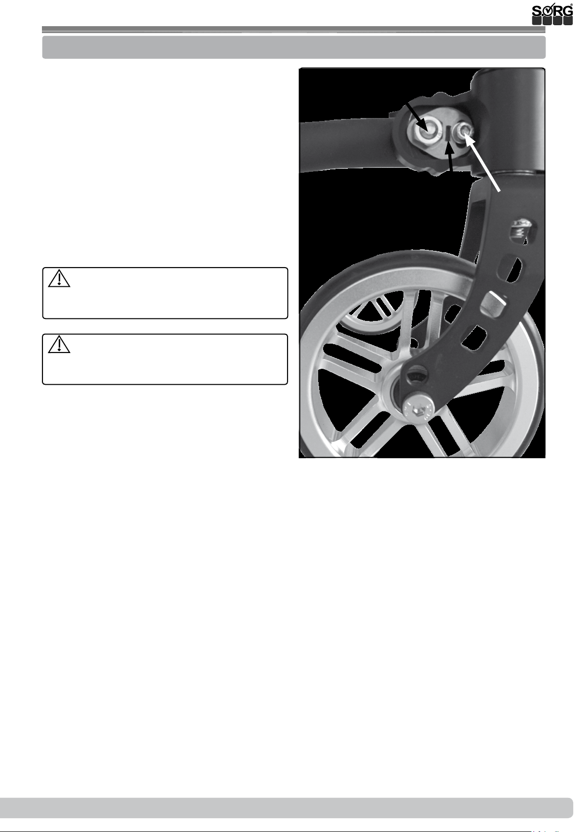
3.6 Assembly Group Brakes
3.6.2 Knee lever brake
With a closed knee lever brake, the wheelchair
with passenger should not be able to move on
a slope of 7% (=6°). All variations of the knee
lever brake are set in the same way.
The correct manner of functioning of the
knee lever brakes can be impaired from:
• too low air pressure in the tires,
• wetness, dirt, snow, ice, etc.
• worn tires or
• too great of a distance between brake
pressing bolt and tire.
When the brake is open, the maximum distance
between brake pressing bolt (A) and tire is:
• standard knee lever brake max. 21 mm,
• pull-to-lock brake max. 11 mm,
• knee lever brake
with rollback blocking max. 11 mm,
• (technical changes reserved).
(1) In order to change the distance between
brake pressing bolt (A) and tire:
• rst check the tire pressure in the rear
wheels (necessary information is found
on the tire cover),
• place the brakes in an opened position,
• loosen both screws (B) on both sides,
• then move the brakes in the necessary
position
• retighten both screws and
• check the brake force.
(1)
(A)
(2)
(B)
(B)
(C)
(A)
After every change made on the rear
wheels, reset the brakes.
In order to attaching a knee lever brake later:
(2)
• place the holding pipe (A), of the knee
lever brake, forward in the upper frame
pipe (here shown transparent) and
• glide the holding pipe so far in the frame
pipe that the distance is small enough.
• Put the screw (B) in one of the holes (C),
• tighten the screw (B) and
• adjust the brake force with the screw (D)
on the brake pad as described above.
(3) When modifying to 12”/16” wheels:
• remove the screws (D) on the holder (A),
• remove the screws (E),
• switch the holders (A) left and right,
• mount the holders (A) back on the hold-
ing pipes (B),
• mount the brakes back on to the holders (A),
• remove the screws (C) and
• place the holding pipes (B) as far back
as possible.
• Readjust the brakes as described above.
(3)
(C)
(B)
(A)
(D)
(D)
(E)
36 of 44
Service Record Loop
SORG
2019-08-15
Page 37

3.7 Assembly Group Frame
3.7.1 Anti-tipper
Height of anti-tipper:
• (1) Remove the screws (A).
• Pull the anti-tipper bar (B) down
• and displace the screw (A) in the alternative holes (C),
• retighten the screws (A)
• and release the anti-tipper bar (B).
• Displacing the anti-tipper in the holes
(E):
• (1) Remove the screws (D),
• place the distance pieces in between the
hole board and the holder (F),
• replace the screws (D)
• and tighten them.
Mounting the anti-tipper afterwards/additionally:
• (1) Place the holder (F) on the holes (D),
• put in the screws (D)
• and tighten them.
(1)
(F)
(E)
(A)
(C)
(B)
(D)
3.7.2 Tipping lever
(2) Assembling the tipping lever:
• Guide the tipping lever (A) in the right
or left frame pipe,
• place the self-locking nuts (B) as well as
the saddle washer and locking washer in
the holes
• and tighten the nuts (B).
(2)
(B)
(A)
2019-08-15
Service Record Loop
SORG
37 of 44
Page 38

3.7 Assembly Group Frame
3.7.3 Outdoor Front End
The greater the seat tilt angle, the higher the
tractability but also the more wobbly the
wheelchair!
(1) Setting the height of the casters:
• Remove the axle with the screw (A),
• place the axle in the alternative holes (B)
of the caster fork and
• retighten the screw (A).
(1) Setting the length and/or width:
• In order to change the length between
the wheelchair and caster remove the
screws (C) on both sides,
• telescope the outdoor front end along
the alternative holes (D) to the length
wanted,
• replace the screws (C) and retighten
them.
• In order to change width of the outdoor front end, proceed the same way
with the screws (E) along the alternative
holes (F).
(1)
(F)
(A)
(E)
(C)
(D)
(B)
The screw pairs (A) and (B) must be moved parallel and symmetrical. There must be at
least one hole free between the screws of each screw pair
The tilting behavior changes crucially when using the outdoor front end and must be
practiced!
38 of 44
Service Record Loop
SORG
2019-08-15
Page 39

4 Repairs and maintenance
4.1 Repairs
Repairs are to be done by your specialized retailer.
4.2 Spare parts
Only original spare parts can be used! They are available at your medical supply store.
The spare parts list can be downloaded at www.sorgrollstuhltechnik.de or can be reques-
ted directly from us.
For a correct delivery of spare parts the appropriate serial number of the wheelchair is to be
stated. You will nd the number on the type label on the wheelchair's frame.
4.3 Maintenance
Clean the wheelchair and all components regularly with a mild household water-based cleaner
and then dry it thoroughly.
In addition, clean the rear wheels and the casters and free the axles of dirt and impurities e.g.
hair etc.).
Wash textile parts:
care directions:
Wipe o pleather, straps and other upholstery:
Care directions:
4.4 Disinfection
Before each disinfection the parts should be cleaned o rst. For disinfection use a household
water-based agent. Observe the instructions of the respective manufacturer.
4.5 Storage
• Carry out cleaning
• Fold foldable wheelchair (if available)
• Adjust seat tilt to 90° (if available)
• If necessary, pack removable textile parts in foil or similar
• Secure the wheelchair from rolling away and getting dirty
• Store in a dry environment without aggressive environmental inuences.
2019-08-15
Service Record Loop
SORG
39 of 44
Page 40

4 Repairs and maintenance
4.6 Reinstatement
Before reuse, a full inspection according the the checklist must be carried out by a specialized
retailer. All disinfection measures for reuse must be carried out according to a validated hygiene plan.
4.7 Disposal
The wheelchair my only be disposed of with the approval of the benefactor. Disposal of the
wheelchair mus be in accordance with the applicable national regulations
4.8 Maintenance/ Inspection
For safety reason and to maintain product liability, an inspection by your retailer is required at
least once a year. This must be carried out and documented according to the following checklist.
Checklist maintenance and care (user)
A poor or neglected maintenance of the wheelchair represents a signicant safety risk.
Before each use:
Please check:
• frame, back tubes, mounting parts and accessories for visible damages, deections, crakcs
or missing/loose screws,
• wheels/quick release axles for rm t,
• the airpressure of the tires, tire tread,
• the function of the brakes,
• rm t of the angle adjustements/eccentric clamps,
• rm t of seat plate/back/foot plate,
• the function of the anti-tipper/seat and back straps,
• if all previously dismantled parts are put on again or rmly locked.
Every 3 months:
(depending on use, earlier)
Please check:
• screws for rm tting
• welds, attachments and accessories for hidden damages, deections or cracks
• tire tread
• the rm t of third-party systems (if available)
Clean the wheelchair and oil all moving parts.
If you notice any defects during maintenance, please contact your specialist retailer im-
mediately and do not use the wheelchair anymore.
40 of 44
Service Record Loop
SORG
2019-08-15
Page 41

4 Repairs and maintenance
Checklist yearly inspection (specialized retailer)
Template (available for download at www.sorgrollstuhltechnik.de/downloadportal)
Preparatory Work
cleaning done
Check:
Frame, back, mounted parts and accessories checked for damage, bends, cracks and
corrosion,
all xing screws checked for rm t and completeness,
casters and rear wheels as well as the associated attachments checked for good condition,
functionality and proper running qualities,
spokes checked for rm t and completeness,
brakes cleaned and maintained,
Locking mechanisms (tripod springs of push handles, quick-release axles, eccentric clamps,
etc.) checked for functionality,
anti-tipper checked for rm t and fuctionality.
Oiling:
moving parts and bearings oiled
Final check:
functional check of all mechanical adjusting devices carried out.
2019-08-15
Service Record Loop
SORG
41 of 44
Page 42

5 Technical specications
5.1 Data and measurements
Model: Loop
Type: 802
German Aid Indix Nr.: 26.99.01.3034/ German Aid Indix Nr.: 26.99.01.1045 with 12“/16”-wheels
All measurements ± 5%
Indication Measurements Comment
size 1
size 2
size 3
back height
back unit
leg supports recording
tilting
back angle
lower leg length
ETRTO wheel size
ETRTO wheel size
ETRTO wheel size
ETRTO wheel size
diameter handrim
handrim
camber
Seat height (SH)
with horizontal seat and
horizontal frame
Wide seat shell base absolutely
Length of seat shell base
frame absolutely
Height seat shell base
frame absolutely
Height of seat shell base
frame folded back
incline
descent
stability
turning circle
load capacity (max.)/
weight testdummy
tare
heaviest piece
wheel
corrosion protection
length of use of the
wheelchair
l
ife cycle of the wheelchair
Normative requirements
SORG
usable width = frame
width + 40 mm
usable width = frame
width + 40 mm
usable width = frame
width + 40 mm
90 - 120°
120 - 550 mm
at 20“
at 22“
at 24“
at 12“
at 20“
at 22“
at 24“
rear wheel
caster 5“/5,5“
rear wheel
caster 6“/7“
rear wheel
caster 5“/6“
rear wheel
caster 7“
min.
max.
min. 610 mm at frame size 1,
max.
min. 900 - 1000 mm at BH 430 mm and 45° push handle
max.
min. 1000 - 1100 mm at BH 580 mm and 45° push handle
min.
max. 620 mm
suitable for driving:
BH 300 mm, rear wheel
12“, caster 4“PU
rear wheel 1,2 - 2,2 kg
commercial pneumatic tires, sizes 1 ", 1 3/8" or puncture-proof tires (same dimensions),
tire ination pressure usually 3-10 bar
material Stainless steel, aluminum
coating Powder coating, galvanizing
3 years at not excessive demand
5 years
The wheelchair meets the requirements of ISO 7176-8 and the requirements
against ignition.
20“/22“
20“/22“
24“
24“
BH 300-420 mm
in 40 mm steps
BH 340-460 mm
in 40 mm steps
BH 380-500 mm
in 40 mm steps
430 or 580 mm optionally
can be moved back by approx. 60 mm
about 60 mm forward displaceable
from -5° to +35°
from +2,5° to +40°
Ø 451 mm with drum brakes, Commercially
Ø 489 mm
Ø 540 mm
Ø 203 mm
444 mm
481 mm
533 mm
Ø 19 mm diameter pipe
0° or 2° 4° limited
410 mm size 1
430 mm size 3
420 mm size 1
440 mm size 3
430 mm size 1
450 mm size 3
445 mm size 1
465 mm size 3
BH + 220 mm
BH + 300 mm
plate (160 mm)
1130 mm at frame size
on and wide footplate (230 mm)
1050 - 1150 mm
1150 - 1250 mm
550 mm
12% = 7° at 0° tilting and 0° back angle
12% = 7°
12% = 7°
ca. 1100 mm depending on the size
120 kg inkl. seat shell
15,1 kg frame, seat plate, trum brake, hand-
suitable from SD 320 mm,
40 mm growable
suitable from SD 320 mm,
40 mm growable
suitable from SD 320 mm,
40 mm growable
optionally
available pneumatic tires in sizes 1
"(25.4mm), 1 3/8" (35mm) - sizes
355mm (20 "), 451mm (22"), 540mm,
(24 ") All puncture-proof tires in the
specied dimensions and 12"in size
ETRTO 47-203
height adjustment
+20/+40/+60 mm
height adjustment
+20/+40/+60 mm
height adjustment
+20/+40/+60 mm
height adjustment
+20/+40 mm
depending on camber and wheels
12“-rear wheel and normal foot
3,
24“-rear wheel, wheel base extensi-
rim, caster, leg support, push handle,
tilting-mechanism
each BH +
each BH +
each BH +
42 of 44
Service Record Loop
SORG
2019-08-15
Page 43

5 Technical specications
5.2 Meaning of labels
The meaning of the individual labes is explained in the texts at the respective place.
If the type plate is damaged or gets lost, a new one can be ordered from SORG Rollstuhltechnik.
Type plate:
manufacturer logo
Reference to
manufacturer
serial number
seat depth
manufacturer address
( )
type number
model name
5.3 Declaration of conformity
SORG Rollstuhltechnik declares that the product Loop
the EG Directive 93/42/EWG Annex VII on medical devices.
seat
depth
max. load
capacity
SORG
Reference to:
Product literature
available.
Reference to: Crash
test passed according to ISO 7176-19
CE-sign
construc-
tion year
back height
a class 1 device is and it complies with
This was conmred by a conformity assessment procedure according to the medical Pruoduct Guidelines Annex VII.
If the product is not modied with SORG wheelchair technology, this declaration
will lose its validity.
2019-08-15
Service Record Loop
SORG
43 of 44
Page 44

Service Record Loop
SORG
company stamp
SORG Rollstuhltechnik GmbH + Co. KG
Benzstraße 3-5
68794 Oberhausen-Rheinhausen
Germany
Fon +49 7254 9279-0
Fax +49 7254 9279-10
info@sorgrollstuhltechnik.de
www.sorgrollstuhltechnik.de
 Loading...