

Page 1
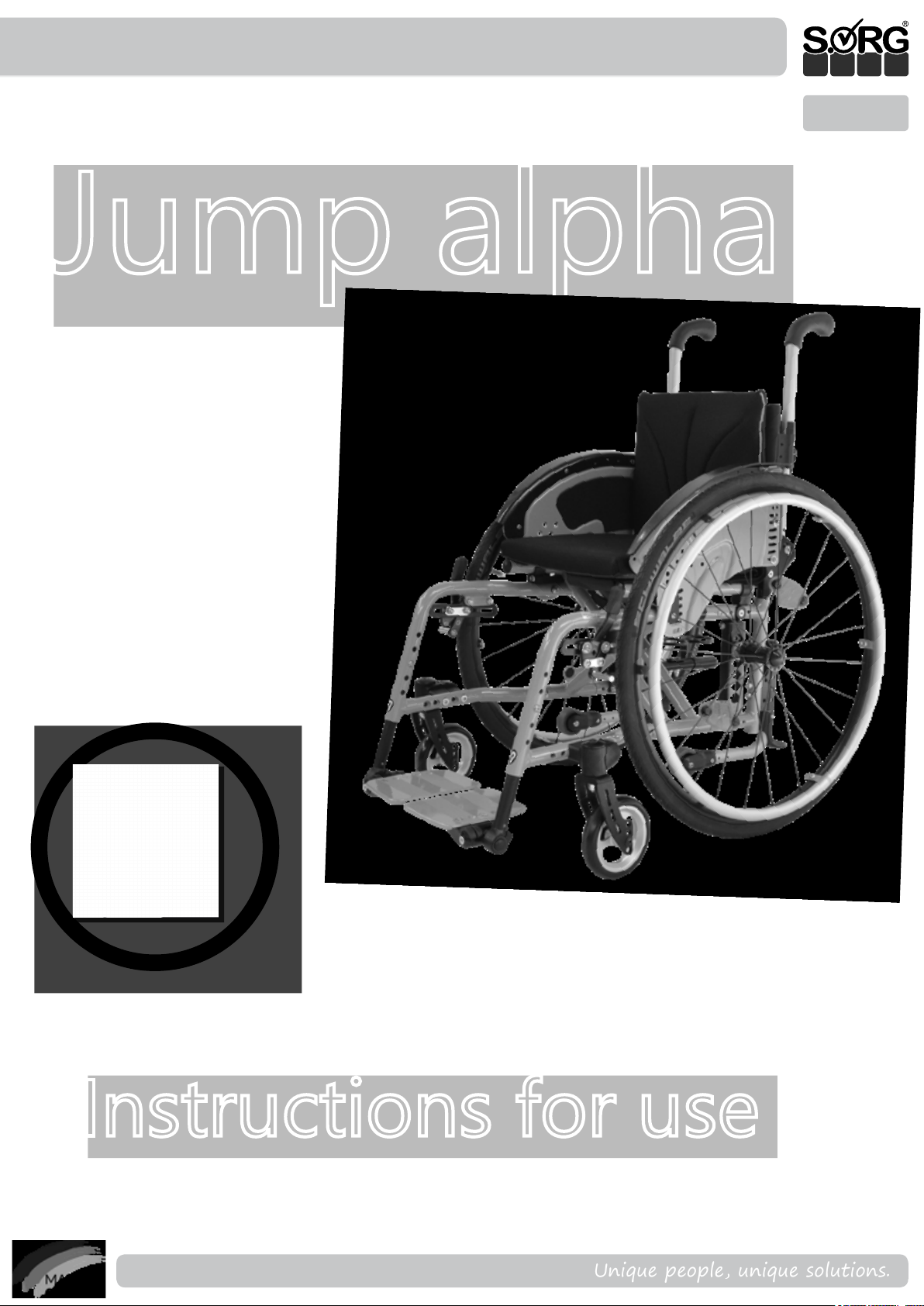
Instructions for use Jump alpha
Jump alpha
ENG
Instructions for use
2019-08-16
Instructions for use Jump alpha
Unique people, unique solutions.
1 of 48
Page 2

Imprint
SORG Rollstuhltechnik GmbH + Co. KG
Benzstrasse 3-5
68794 Oberhausen-Rheinhausen / Germany
Revision status
2019-08-15
Technical status
Technical changes and misprints reserved. The
pictures in this instructions for use can dier
from the actual equipment components.
However, a corresponding conduction is possible.
Copyright
All texts, pictures and graphics underlie copyright protection. All rights, including copying,
publishing, editing and translating, remain
reserved. © by SORG Rollstuhltechnik GmbH + Co.
KG Benzstraße 3-5, 68794 Oberhausen-Rheinhausen / Germany.
Our terms and conditions can be found
on our order forms and at www.sorgrollstuhltechnik.de/impressum
2 of 48
Instructions for use Jump alpha
2019-08-16
Page 3

Table of Content
1 Wheelchair overview 5
2 General information 6
2.1 Preface 6
2.2 General information regarding instruc-
tions for use 6
2.2.1 Signs and symbols 7
2.2.2 Intended purpose 8
2.2.3 Indication 8
2.2.4 Contraindication 8
2.3 General safety information 9
2.3.1 Loading and transport without
occupants 11
2.3.2 Transport of the wheelchair with
passengers in the motor vehicle 11
2.3.3 Other important information 13
3 Handling 15
3.1 Handling driving wheel 15
3.1.1 General information regarding wheels 15
3.1.2 Tyre ination pressure 15
3.1.3 Quick-release axles 15
3.1.4 Double hand rim-wheels 16
3.2 Handling swivel caster 17
3.2.1 General information regarding
swivel casters 17
3.2.2 Caster track lock 17
3.3 Handling seat and back 18
3.3.1 General information regarding backs 18
3.3.2 Fixed seat plate (SeatFix) 18
3.3.3 Fixed seat plate with locking
mechanism (SeatFix) 19
3.3.4 Firm curved back plate 20
3.3.5 Back with raster 21
3.3.6 Back with gas pressure spring 22
3.3.7 Back extension 22
3.4 Handling: folding up and
unfolding 23
3.4.1 General information regarding
folding up and unfolding 23
3.4.2 of seat and back cover 24
3.4.3 of SeatFix and/or rm curved
back plate 25
3.5 Handling pushing aid 26
3.5.1 General information regarding
pushing aids 26
3.5.2 Push handles 27
3.5.3 Handle bar 28
3.6 Handling leg support 29
3.6.1 General information regarding
leg supports 29
3.6.2 Foldable footrest with
locking mechanism 30
3.7 Handling brake 31
3.7.1 General information regarding
brakes 31
3.7.2 Wheel lock 31
3.7.3 Drum brake 33
3.7.4 Reverse-roll locking 33
3.8 Handling anti-tipper 34
3.8.1 General information regarding
anti-tipper 34
3.9 Handling headrest 35
3.9.1 General information regarding
headrest 35
3.10 Handling abduction wedge 36
3.10.1 General information regarding
abduction wedge 36
3.11 Handling therapy table 37
3.11.1 General information regarding
therapy table 37
3.12 Handling lateral truss pad 37
3.12.1 General information regarding
lateral truss pad 37
3.13 Handling steering & pushing aid 38
3.13.1 General information regarding
steering and pushing aids 38
3.14 Handling one-hand steering aid 39
3.14.1 General information regarding
one-hand steering aid 39
3.15 Handling sun shade 41
3.15.1 General information regarding
sun shade 41
4 Repairs and maintenance 42
4.1 Repairs 42
4.2 Spare parts 42
4.3 Maintenance 42
4.4 Disinfection 42
4.5 Storage 42
4.6 Reinstatement 43
4.7 Disposal 43
4.8 Maintenance/ inspection 43
5 Technical data 45
5.1 Data and measurements 45
5.2 Meaning of labels 46
5.3 Declaration of conformity 46
6 Verication of yearly inspection 47
2019-08-16
Instructions for use Jump alpha
3 of 48
Page 4

4 of 48
Instructions for use Jump alpha
2019-08-16
Page 5
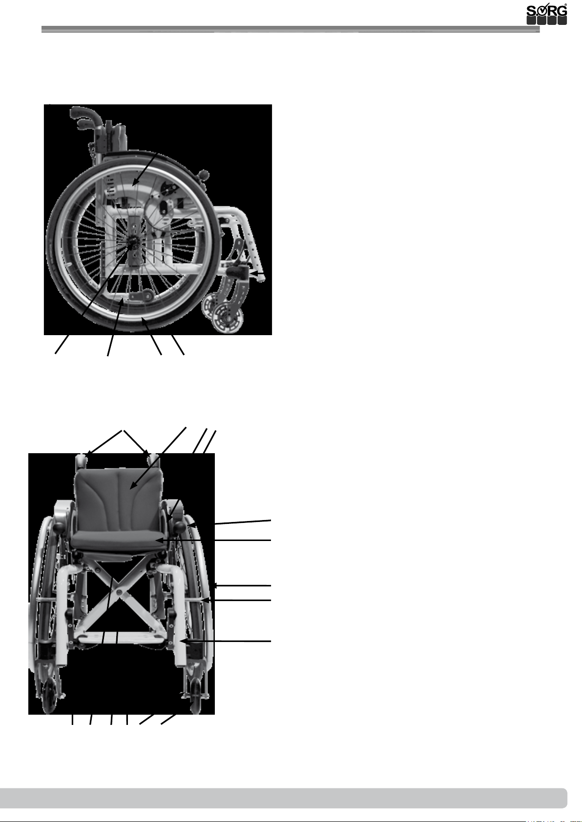
1 Wheelchair overview
1
15
2 3
111214 13
4
5
1 Push handles
2 Back
3 Side guard
4 Clothes guard
6
5 Wheel lock (cable control)
6 Seat
7 Frame
7
8 Caster adapter
9 Caster fork
10 Swivel caster
8
9
11 Driving wheel
12 Handrim
13 Anti-tipper
14 Quick-release axle
10
15 Eccentric clamp (for extendable push handles)
16
17
18
19
20
21
22
23
24
16 Push handles
17 Back
18 Clothes guard
19 Side guard
20 Brake lever
21 Seat cushion
22 Handrim
23 Brake pressure bolt
24 Frame
25 Swivel caster
26 Caster fork
27 Foot plate (continuous)
28 Crossbrace
29 Utensil pocket
30 Foot plate intake
2019-08-16
30
29
25262728
Instructions for use Jump alpha
5 of 48
Page 6
2 General information
2.1 Preface
A warm welcome to the SORG family – many thanks for the trust you have placed in us and for
choosing our product.
This wheelchair has been individually tailored to meet your specic requirements.
You will nd the usage and adjustment instructions below so that you can use
the wheelchair in everyday life without tools. Please observe these instructions and handle the
wheelchair carefully so that you can enjoy it for as long as possible.
Please do not hesitate to contact us if you have any questions about this or any other product.
We hope you enjoy using your SORG product.
Your SORG team
2.2 General information regarding instructions for use
These instructions for use contain safety information and handling instructions that are necessary for the correct use of the product.
All settings, adjustments and repairs beyond the scope of these instructions for use, and the
annual inspection, must be carried out by a qualied specialist dealer.
You can find more information about this in our service record, which can be accessed at
www.sorgrollstuhltechnik.de
The user and specialist dealer must have read and understood these instructions before commissioning. These instructions for use cover all equipment variants of the product. Have your
consultant instruct you on the safe handling of the wheelchair and your individual equipment
variants on level ground and with the support of an accompanying person.
Those with impaired vision can nd these instructions for use on our website www.sorgroll
stuhltechnik.de as PDF and audio les.
Please contact your specialist dealer or our team if you have any questions or comments
(+49 7254 9279-0).
Keep these instructions for use in a safe place. All annual inspections carried out must be
documented by the specialist dealer.
6 of 48
Instructions for use Jump alpha
2019-08-16
Page 7
2 General information
2.2.1 Signs and Symbols
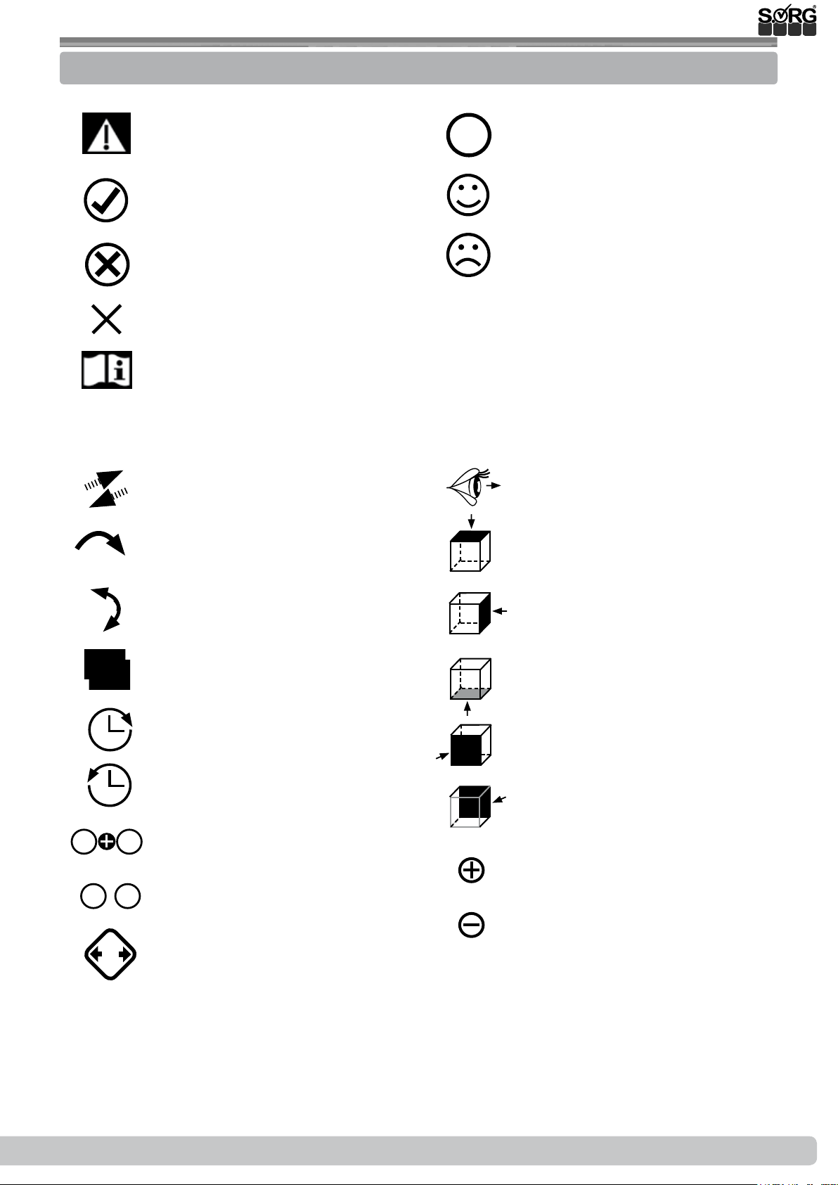
ATTENTION! Warnings for per-
sonal Safety aspects that are of
the utmost importance.
important detail
USE
CORRECT safety adjustment/ use
INCORRECT adjustment /use
NOT ALLOWED
References to additional/ con-
tinuing reading.
push/ pull/ insert/ move/ remove
Push in specic direction
(A); (B)
correct or proper use/setting
incorrect or improper use/setting
reference from text to detail
View
view from top
1. 1.
2.
1.
;
2x
Setting or adjusting the angle
open/close
Turn clockwise
Turn
counterclockwise
steps to be done
at the same time
steps to be done after each other
Steps to be taken on
at the same time
view from the side
view from the bottom
view from the front
view from the back
fasten parts
remove parts
2019-08-16
Instructions for use Jump alpha
7 of 48
Page 8
2 General information
2.2.2 Intended purpose
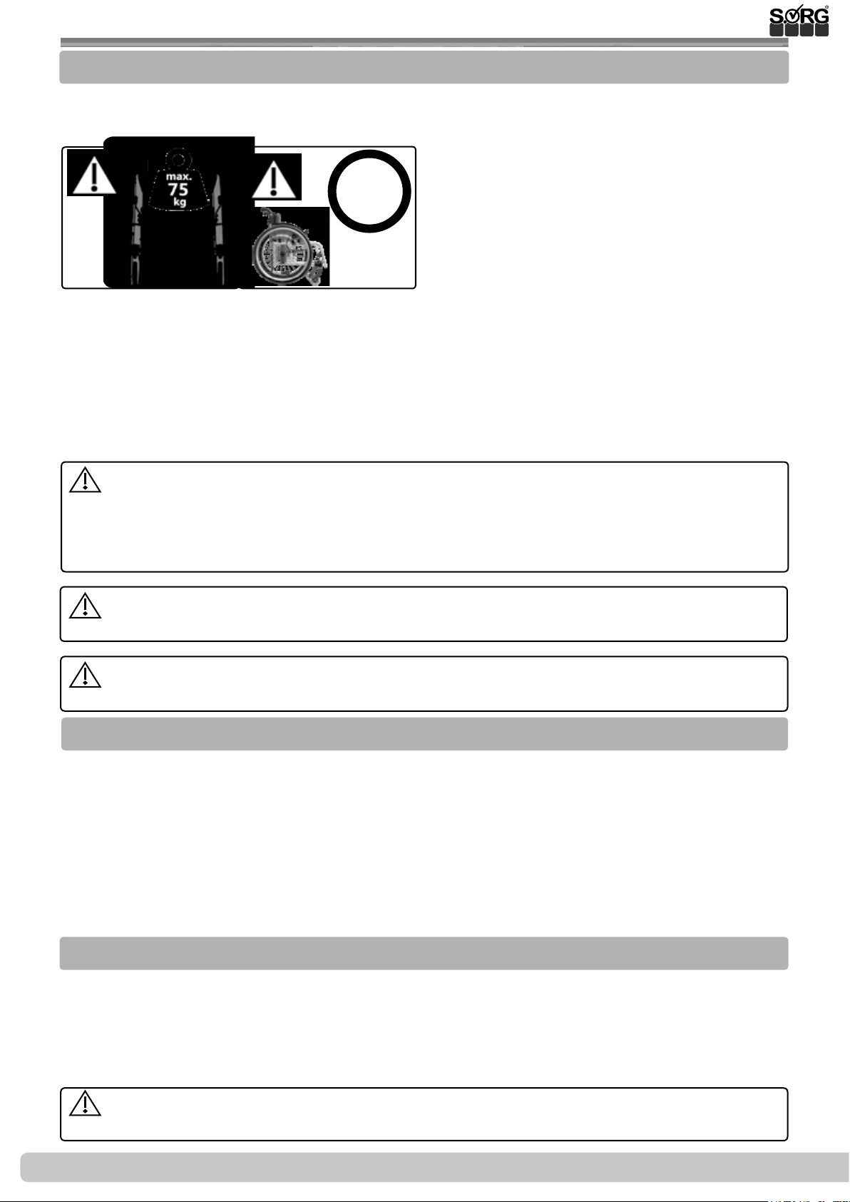
The Jump alpha is a light and exible active wheelchair with a foldable aluminium frame designed for indoor and outdoor use.
8
km/h
The wheelchair is designed solely for the transport of the person for whom it has been specially
adapted by a qualied specialist dealer.
Parents or authorised guardians must ensure that the information in the instructions for use is
followed for children or persons with impaired capacities.
The safest possible use of the aid is only possible on level, rm and dry ground with the antitipper
activated and with the help of an accompanying person.
Any use beyond this entails taking a variety of risks for which only the user themselves can
take responsibility. This requires sucient competence in identifying and avoiding hazards and
safe handling of the aid by the user! An increased hazard potential must be taken into account,
especially in wet conditions, ice, loose ground, slopes, obstacles, close proximity to water, road
trac, narrow spaces, etc.
Only use the wheelchair for its intended purpose. Any improper use of the product in-
volves considerable risks and will invalidate product liability.
The large variety of combinations for seat and wheel position means that settings
can be made that are outside the safety and application range.
2.2.3 Indication
Use is suitable for the following functional impairments, among others:
• (infantile) cerebral palsy
• spina bida,
• paralysis,
• multiple sclerosis,
• muscle disorders,
• impairments of the lower extremities,
• cardiovascular insuciency,
• rheumatic disorders.
2.2.4 Contraindication
Use is unsuitable for:
• serious tonus dysregulation (spasms etc.)
Active use is unsuitable for:
• cases of extremely restricted perception or impaired competence to act (active engage-
ment in road trac without an accompanying person is not possible).
We accept no liability for damage to persons or objects resulting from the circumstances
described above.
8 of 48
Instructions for use Jump alpha
2019-08-16
Page 9
2 General information
2.3 General safety information
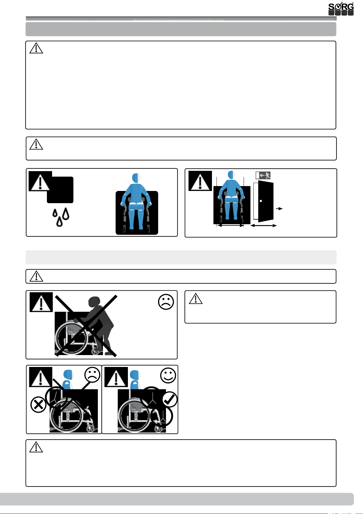
Before each use, check:
• the frame, back tubes, add-on parts and accessories for visible damage, bending, cracks
or missing or loose screws,
• the wheels and quick-release axles for tightness,
• that the ination pressure and tyre tread are sucient,
• that the brakes are working properly,
• that the angle adjustment elements/ eccentric clamps are secure,
• that the seat plate/ back/ footrest are tightly locked,
• that the anti-tipper/seat and back belts are functioning correctly,
• that all previously dismantled components have been reconnected and rmly locked.
There is a risk of injury (e.g. due to crushing) from all rotating, swivelling or foldable com-
ponents, even during adjustment and repair work and during transport.
-10 to + 41°C
x >700 mm
!
y > x + 50 mm
30 - 70%
x
y
Danger of tipping over and overturning
Occupants must only get in and out of the wheelchair with the wheel lock and anti-tipper engaged.
Do not use the footrest(s) for getting in
and out of the wheelchair, The wheelchair
might tilt forward.
accessories:
2019-08-16
The risks listed as examples below may occur when dismantling the following parts/
• Cushions: lack of hygiene / pressure points
• Headrest: loss or missing headrest during transport
• Driving wheels: loss of the back (use of wheelchair not possible)
Instructions for use Jump alpha
9 of 48
Page 10
2 General information
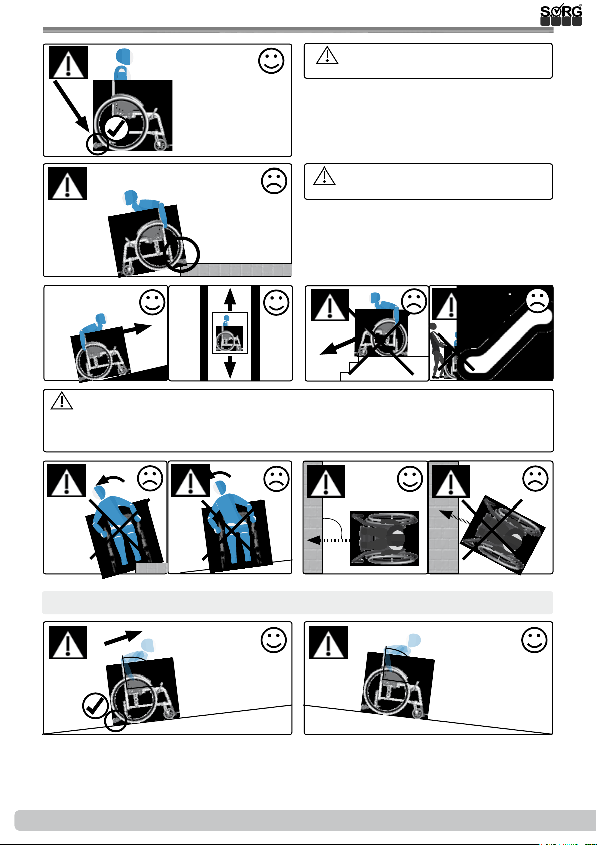
We strongly recommend the use of the
anti-tipper.
The anti-tipper must be deactivated
when moving down over edges.
Only negotiate stairs with the help of experienced assistants. The anti-tipper must be
deactivated when doing so. The wheelchair must always be carried by the frame only, never
by the seat shell, the extendable push handle(s), push bail, handle bar, leg supports and/or the
footrest(s)!
90°
max 7°
Inclines, downward gradients and obstacles
90°
90°
10 of 48
max 7°/ 12% max 7°/ 12%
Instructions for use Jump alpha
2019-08-16
Page 11
2 General information
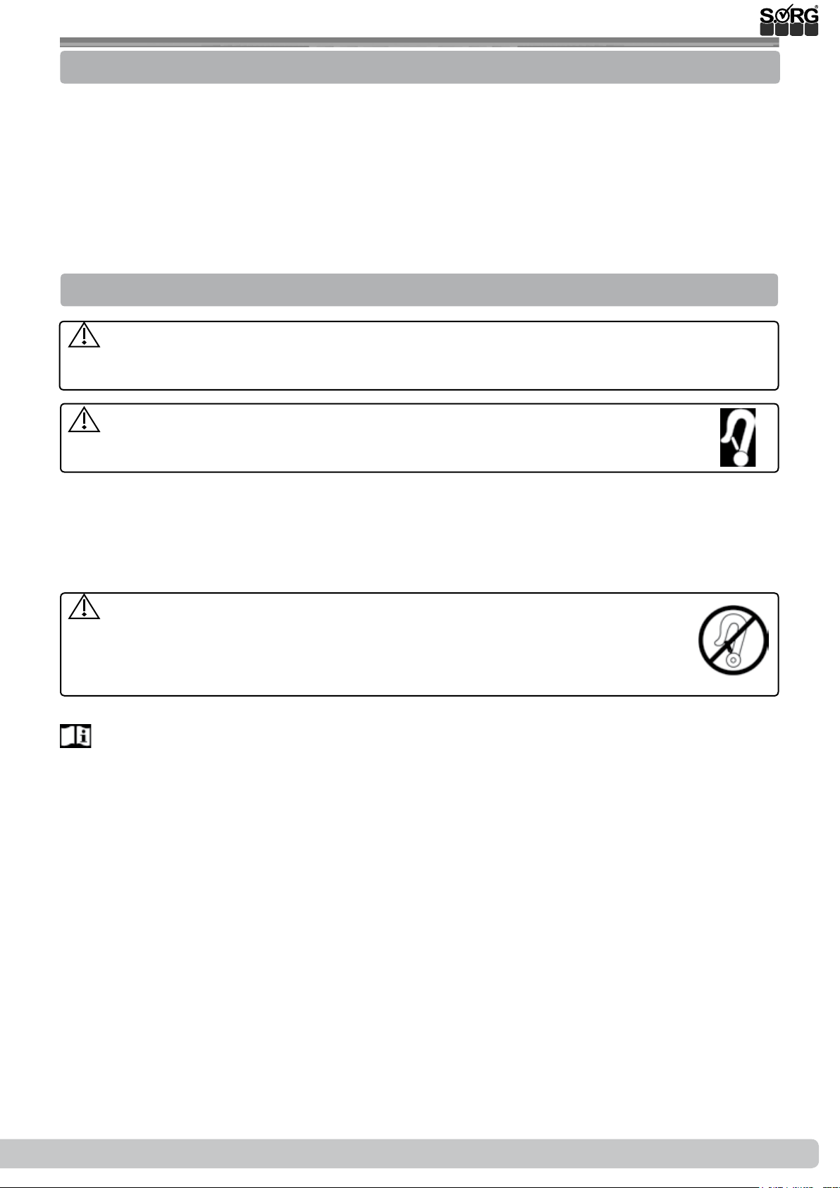
2.3.1 Loading and transport without occupants
Make sure that the packing size you require is suitable and secure the wheelchair and all dismantled components with sucient load securing. The wheelchair is suitable for transport
(land/air) in principle. Inform yourself about suitable load securing precautions before wheelchair transport.
Carrying points:
• Seat tubes when folded
• Front frame tubes of leg supports l/r
• But not on the footrests.
2.3.2 Transport of the wheelchair with passengers in a motor vehicle
The characteristics of wheelchairs mean that they can never achieve the stable properties
of a xed seating system in a vehicle. Wherever possible, we recommend using a xed vehicle
seat to transport a person in a motor vehicle.
Only wheelchairs that have successfully passed a crash test in accordance with
ISO 7176-19 may be used as seats in motor vehicles. Successfully tested wheelchairs
are provided with the symbol for the attachment point on the axed nameplate.
The Jump alpha has been successfully tested in accordance with ISO 7176-19
and is therefore approved for use as a seat in a motor vehicle provided that it is
tted with the necessary restraint systems.
Please check whether your wheelchair is custom-made because
it may not be suitable for use as a seat in a motor vehicle. If this is the case, the
symbol for the attachment point will be missing from the nameplate and the
wheelchair will be marked with a warning, represented by the crossed-out symbol
for the attachment point.
More information can be found in the crash test brochure at www.sorgrollstuhltechnik.de/
downloadportal.
We can recommend the following manufacturers of restraint systems:
• SORG restraining eyelets on wheelchairs
• AMF-BRUNS GmbH & Co.KG
• Q‘Straint Europe
2019-08-16
Instructions for use Jump alpha
11 of 48
Page 12
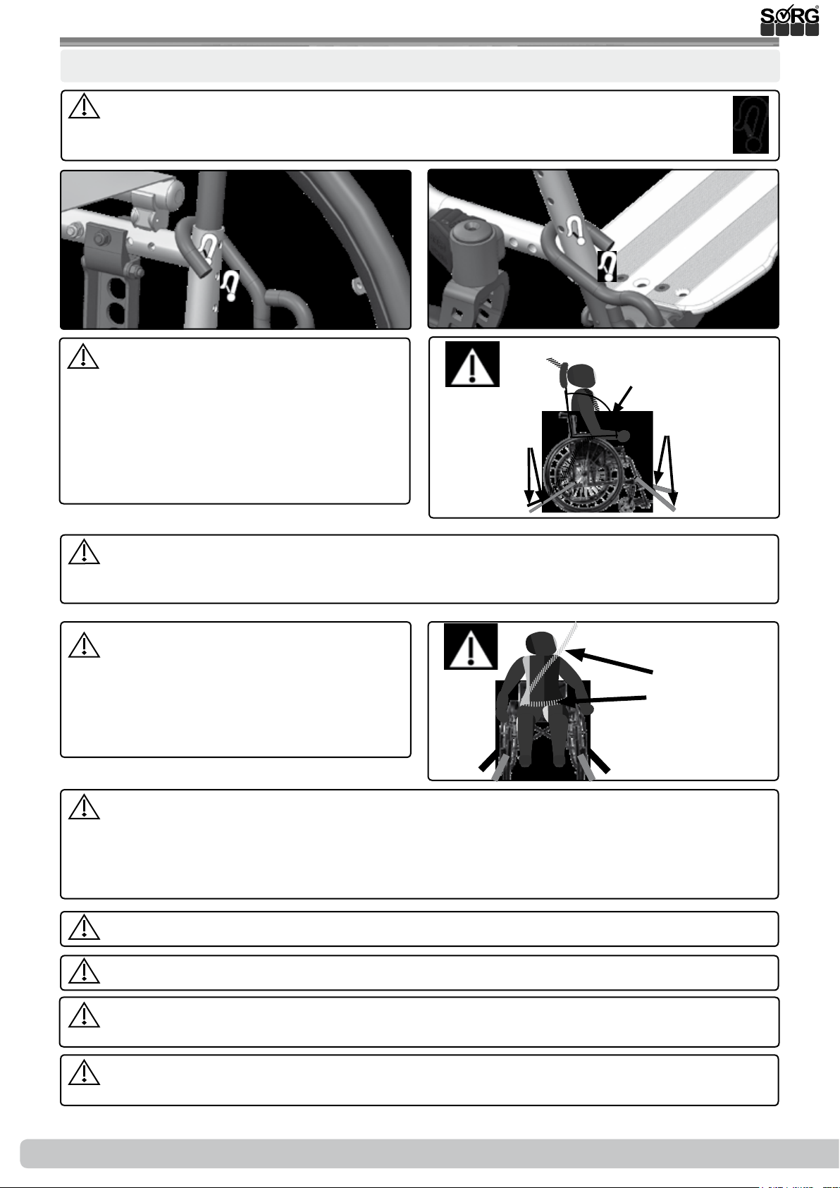
2 General information
Attachment points/methods for transport in motor vehicles
When using the wheelchair as a seat in a motor vehicle, only the positions marked
with the symbol for the attachment point should be used. These can usually be found
at the back left and right (1) and at the front left and right. (2)
(1)
The wheelchair must be xed with a
4-point wheelchair restraint system anchored
to the vehicle in accordance with ISO 10542.
These may be carabiner hooks, S-shaped
hooks or plug-in fasteners. The wheelchair
restraint system must be securely fastened
and used in accordance with the user manual
of the manufacturer. (3A+B)
If the wheelchair is equipped with a back angle-adjustment or tilt mechanism, the occupant must sit in an upright position at a 90° back angle during transport (3). Leg supports that
can be swung up must be adjusted to the lowest position.
(2)
(3)
90°
(B)
(A)
The user must be additionally secured
with a xed lap belt (4C) approved for trans-
port in accordance with ISO 10542 and a
vehicle-anchored shoulder belt (4D) so that
the risk of head and upper body injuries can
be minimised to the greatest extent possible.
The seat belts must not be twisted during use, nor must they be guided over any structur-
al components, which would keep them away from the body. They have to be tight and rm
without impairing user comfort. The lap belt buckle must be positioned between the pelvic
bones (if possible in the middle). The buckle tongues on the lap belt for fastening the shoulder belt should be located on the outside of the pelvis where possible.
All belts used for transport must be regularly inspected for damage.
A headrest suitable for transport must be used.
The wheelchair must only be used as a forward facing seat in motor vehicles in accordance
with ISO 7176-19. No transport with the wheelchair facing sideways!
(4)
(D)
(C)
Immediately contact your authorised dealer after a collision to check the carriage, frame
and brakes and have any damage repaired by a specialist without delay.
12 of 48
Instructions for use Jump alpha
2019-08-16
Page 13
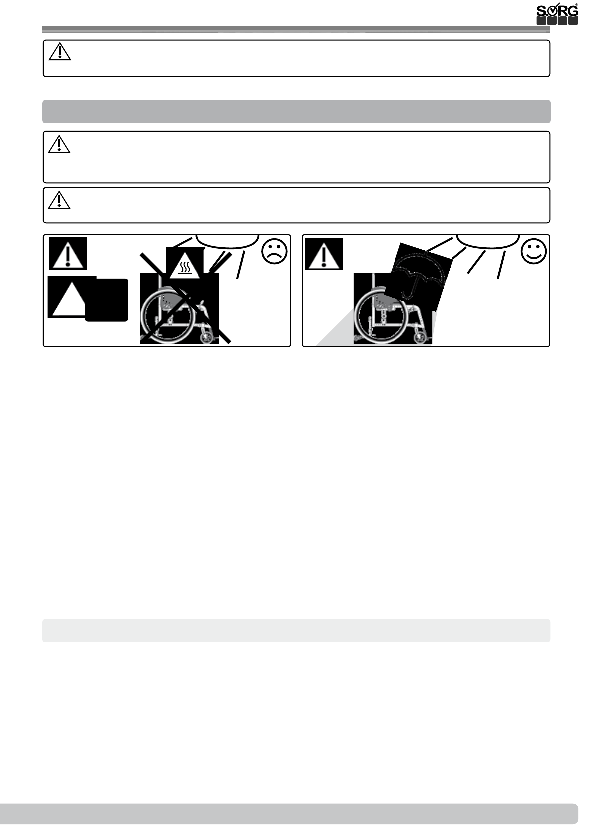
2 General information
Any braking devices fitted to the wheelchair must be in the braked position when the
wheelchair is transported in a motor vehicle.
2.3.3 Other important information
The wheelchair’s textile materials have been tested and veried for re resistance in com-
pliance with the applicable standards. Nevertheless, there is a risk of ignition of the ame
retardant textile components. Keep any sources of ignition away from the wheelchair.
The wheelchair must neither be exposed to excessive moisture nor come into contact with
salt water.
°C
> 42°C
When conguring the wheelchair, pelvic restraints (lap belts as positioning aids) can be optionally purchased via the SORG order sheets or by ordering from the replacement parts catalogues.
Your specialist dealer will carry out the assembly.
The product may interact with electromagnetic elds (e.g. shop antitheft devices) in individual
cases. This poses no danger to the user and/or the attendant.
The wide variety of settings available means that not all limit values can be complied with in all
possible congurations in accordance with the Regulation (EU) on the technical specications for
interoperability relating to accessibility of the Union's rail system for persons with disabilities and
persons with reduced mobility.
Please contact your specialist dealer or us as the manufacturer if you experience any issues with
the wheelchair. Product recalls etc. will be published on our website www.sorgrollstuhltechnik.
de. You can also nd the respective contact persons there.
Corrosion protection
The product has been designed with corrosion protection in mind when selecting the materials
(e.g. plastic, aluminium, stainless steel). All materials prone to corrosion are surface-treated and
are therefore protected.
The wheelchair must be dried thoroughly if it becomes wet.
2019-08-16
Instructions for use Jump alpha
13 of 48
Page 14

2 General information
Combination with products from other manufacturers
The wheelchair must only be combined with the electric auxiliary drives approved by the
manufacturer. The supplier of the auxiliary system or the authorised specialist dealer is solely
responsible for restrictions or adaptations as well as the installation itself. Please ask the manu-
facturer of the auxiliary drives for the specic requirements.
The combination of a wheelchair and electric auxiliary drive can cause particular stresses
that may damage the wheelchair. Only approach obstacles slowly and overcome them with
great care to ensure that little force is applied to the casters, driving wheel and wheelchair as a
whole.
14 of 48
Instructions for use Jump alpha
2019-08-16
Page 15
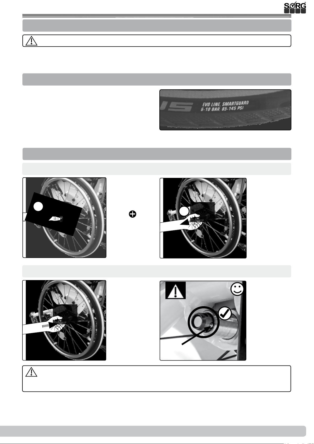
3.1 Handling driving wheel
3.1.1 General information regarding wheels
Frictional heat is generated by braking the wheels on the handrims.
Handrim covers can stretch when exposed to heat and become detached from the handrim.
3.1.2 Tyre ination pressure
You can nd the right operating pressure on
the tyre casing - usually 3-10 bar. (1)
If the tyre is at, please contact
your specialist dealer.
3.1.3 Quick-release axles
Remove:
(1)
1.
(1)
(2)
1.
Insert:
(1)
(2)
(A)
(2) After insertion, the locking ball (A) must be visibly protruding. Pull at least 1x after
each insertion to test whether the quick-release axle is engaged. It should no longer be possible to pull the wheels outwards.
2019-08-16
Instructions for use Jump alpha
15 of 48
Page 16
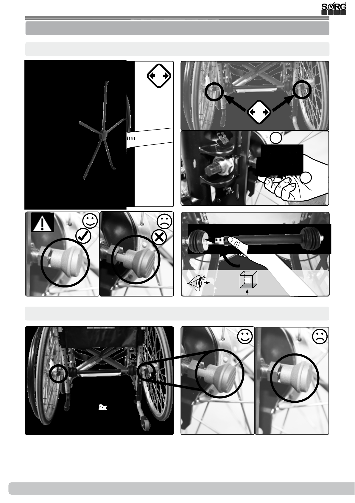
3.1 Handling driving wheel
3.1.4 Double hand rim-wheels
Insert:
(1)
(3a)
(3b)
2x
(2a)
(4)
2x
1.
90°
2.
Remove: Proceed accordingly in reverse order
(1)
2x
(2a)
(2b)
16 of 48
Instructions for use Jump alpha
2019-08-16
Page 17
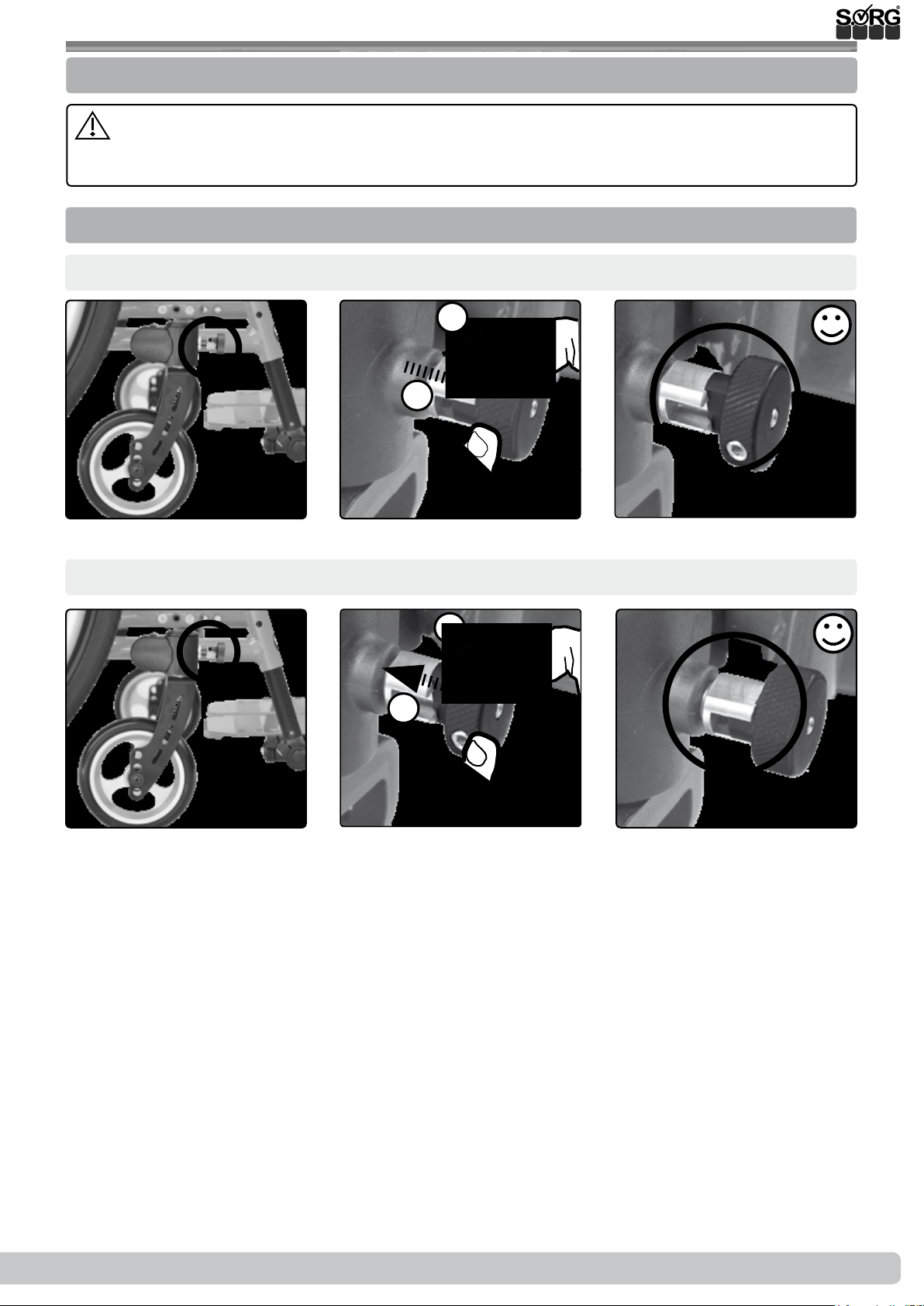
3.2 Handling swivel caster
3.2.1 General information regarding swivel casters
Incorrectly adjusted swivel casters or excessive speed can cause the casters to utter.
Immediately slow down at the rst sign of uttering and have the swivel casters readjusted by
a specialist dealer.
3.2.2 Caster track lock
Unlock:
(1)
Lock:
(1)
(1)
(2)
(2)
2.
1.
2.
1.
90°
90°
(3)
(3)
2019-08-16
Instructions for use Jump alpha
17 of 48
Page 18
3.3 Handling seat and back
3.3.1 General information regarding back
Check the secure t of the back after each change.
In the case of angle-adjustable backs or (seating unit) tilt mechanisms, it is essential to activate the anti-tipper from a setting of > 90°. The head must be supported (e.g. by a headrest)
during back angle-adjustment or tilting.
Only activate the (seating unit) tilt mechanism or angle adjustment with the brakes applied.
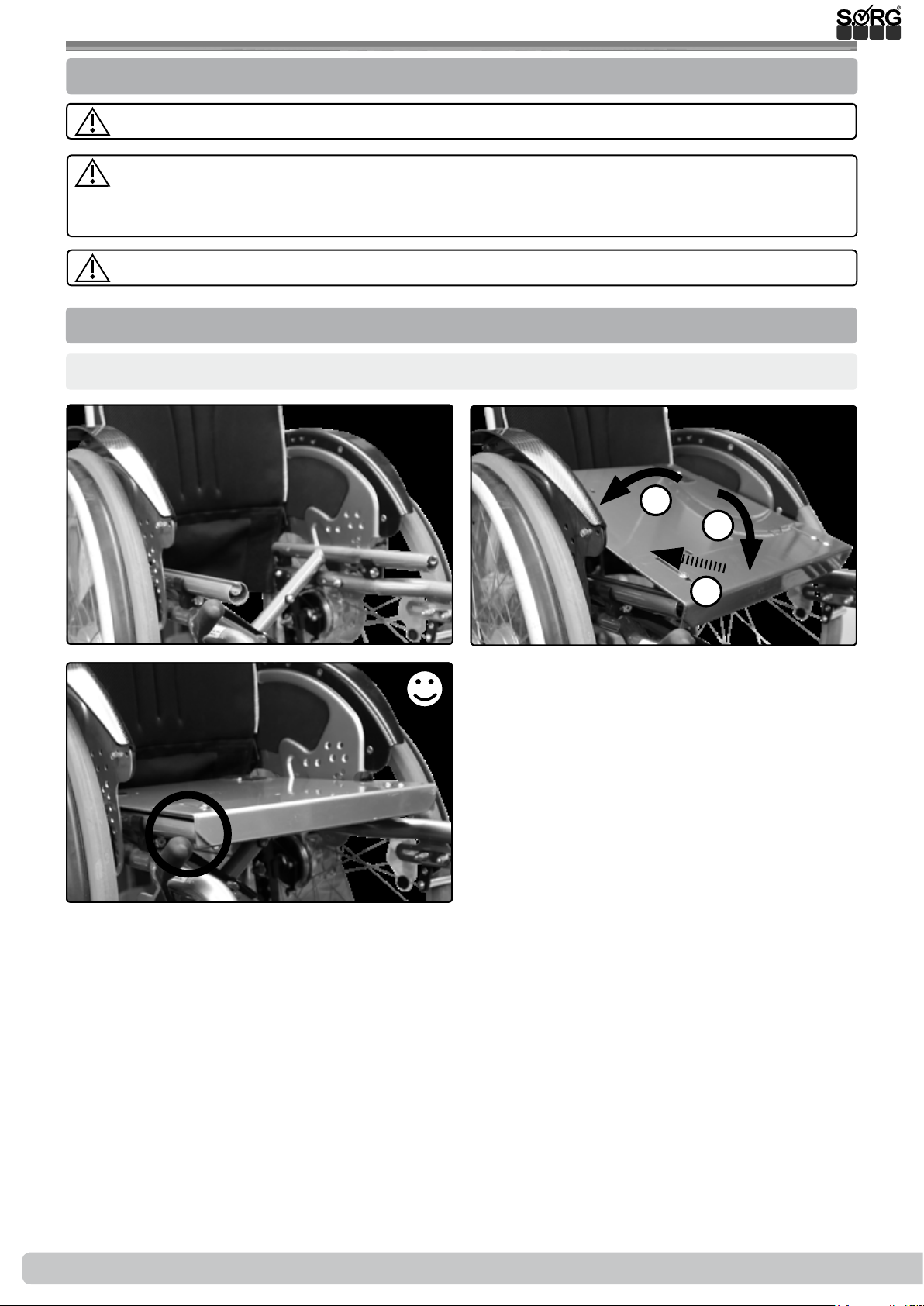
3.3.2 Fixed seat plate (SeatFix)
Insert (remove: proceed accordingly in reverse order):
(1)
(3)
(2)
3.
1.
2.
18 of 48
Instructions for use Jump alpha
2019-08-16
Page 19
3.3 Handling seat and back
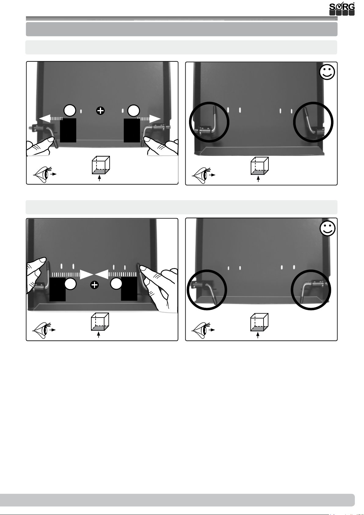
3.3.3 Fixed seat plate with locking mechanism (SeatFix)
Lock:
(1)
Unlock:
(1)
1.
180°
(2)
1.
180°
(2)
1.
180° 180°
1.
2019-08-16
Instructions for use Jump alpha
19 of 48
Page 20
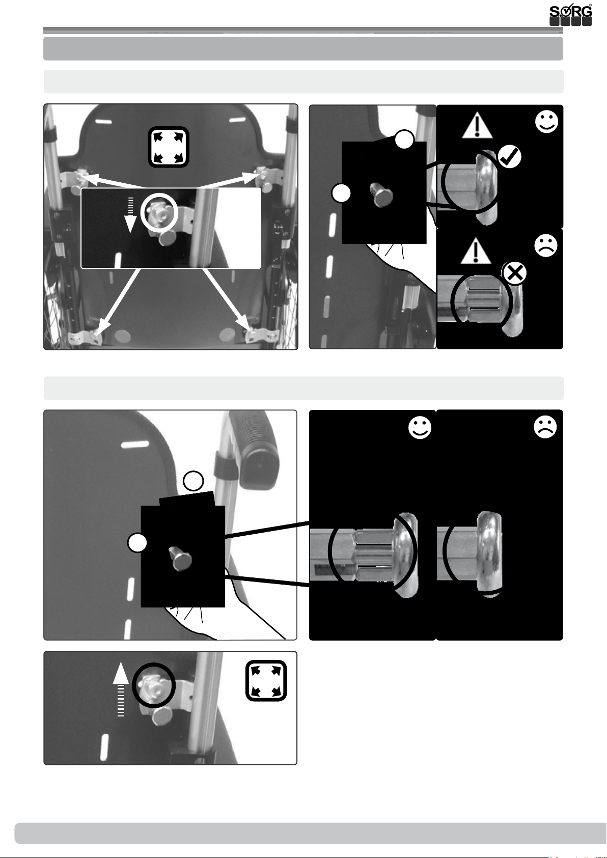
3.3 Handling seat and back
3.3.4 Firm curved back plate
Lock:
(1)
Unlock:
4x
(2)
2.
90°
(3a)
1.
(3b)
(1)
(3)
1.
2.
90°
4x
(2a)
(2b)
20 of 48
Instructions for use Jump alpha
2019-08-16
Page 21
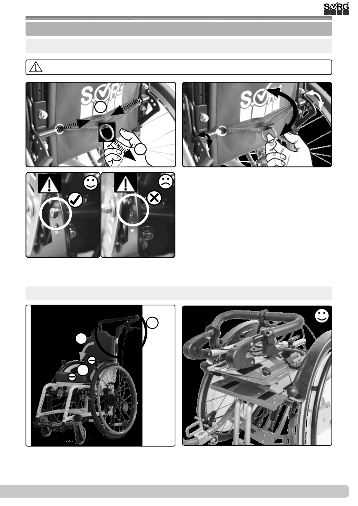
3.3 Handling seat and back
3.3.5 Back with raster
Shift:
The anti-tipper must always be activated before a new back angle position is used.
(1)
(3a)
(2)
2.
1.
(3b)
Fold down (straighten: proceed accordingly in reverse order):
(1)
2.
3.
1.
(2)
2019-08-16
Instructions for use Jump alpha
21 of 48
Page 22
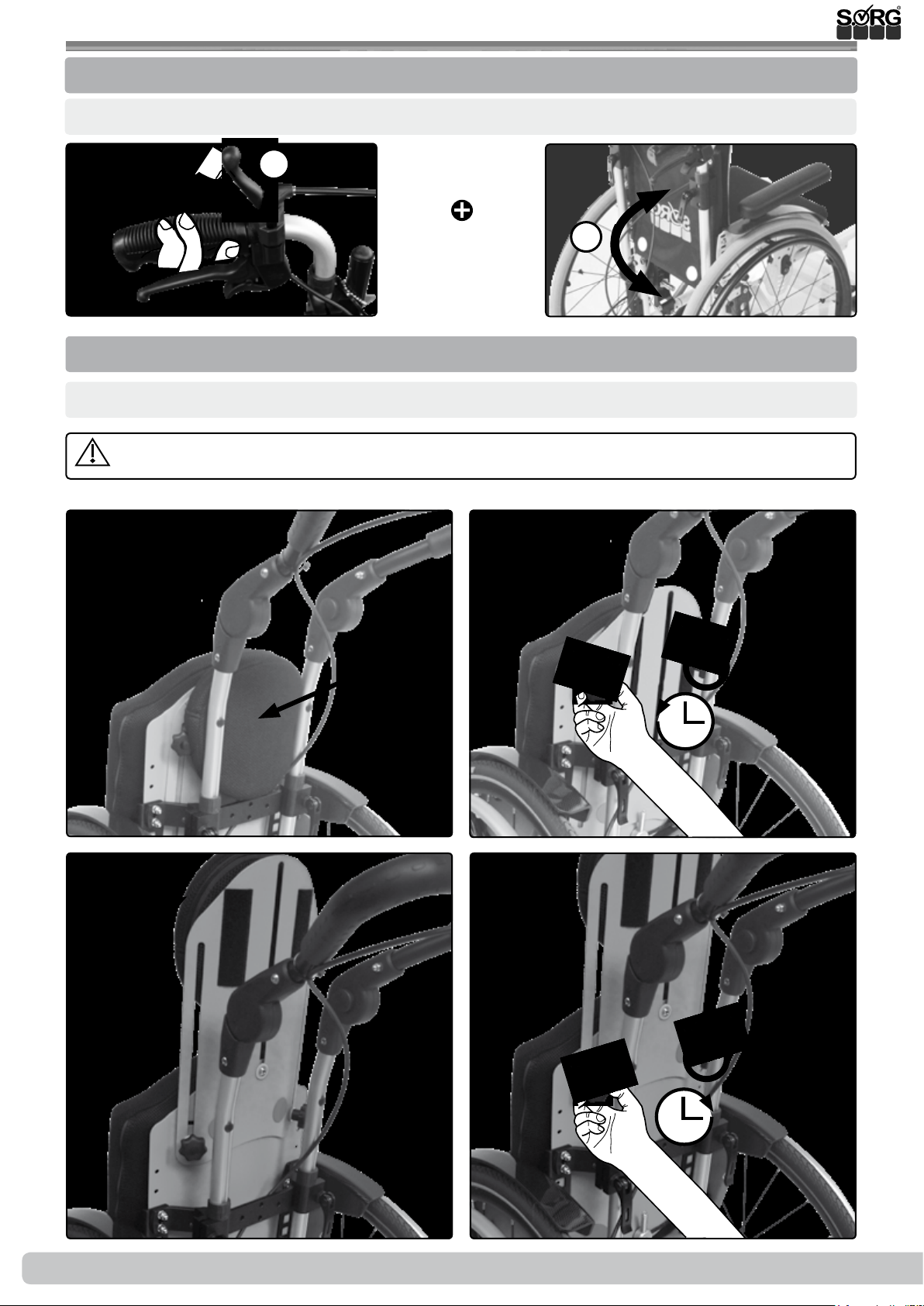
3.3 Handling seat and back
3.3.6 Back with gas pressure spring
Shift:
(1)
3.3.7 Back extension
Pull out (lower: proceed accordingly in reverse order):
The lowerable back extension is not suitable as a headrest in a motor vehicle!
1.
1.
(1) (2)
(3)
22 of 48
(4)
Instructions for use Jump alpha
2019-08-16
Page 23
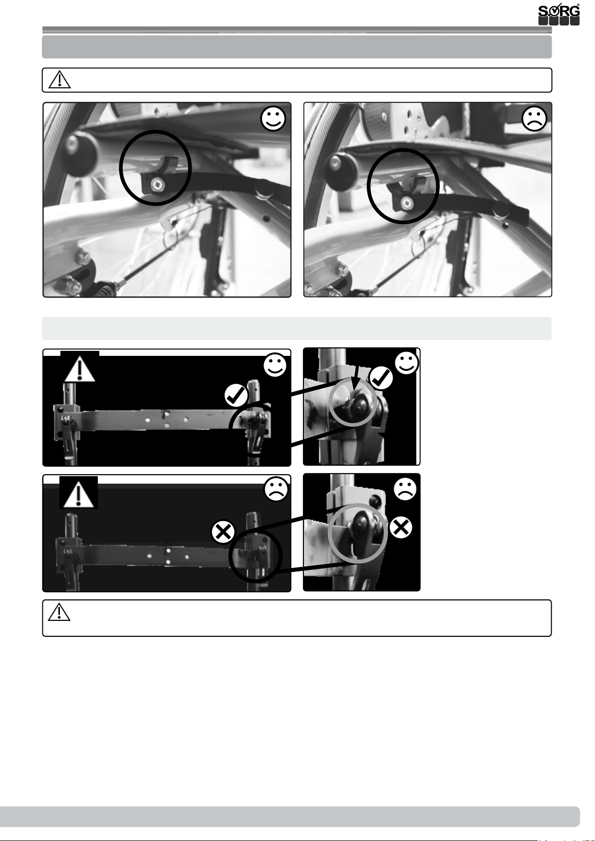
3.4 Handling folding up and unfoldin
3.4.1 General information regarding folding up and unfolding
When folding the wheelchair, pay attention to the crushing hazard posed by the crossbrace.
(1a)
Stabiliser bar:
(1a)
(1b)
(1b)
(A)
(B)
(2a)
The notch (A) of the stabiliser bar must be seated up to the stop in the guide of the
eccentric clamp (B) and this must be rmly closed.
(2b)
2019-08-16
Instructions for use Jump alpha
23 of 48
Page 24
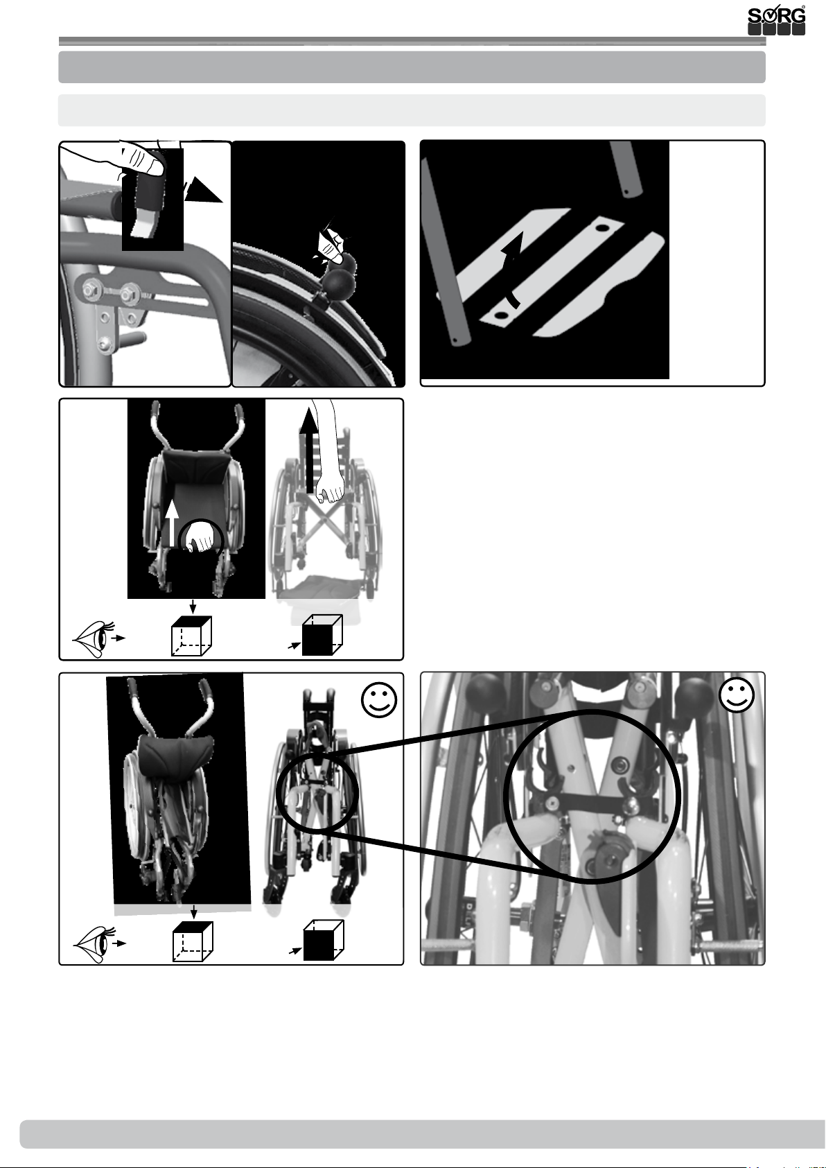
3.4 Handling folding up and unfolding
3.4.2 of seat and back cover
Fold up (unfold: proceed accordingly in reverse order):
(1)
(3)
(2)
(4)
(5)
24 of 48
Instructions for use Jump alpha
2019-08-16
Page 25
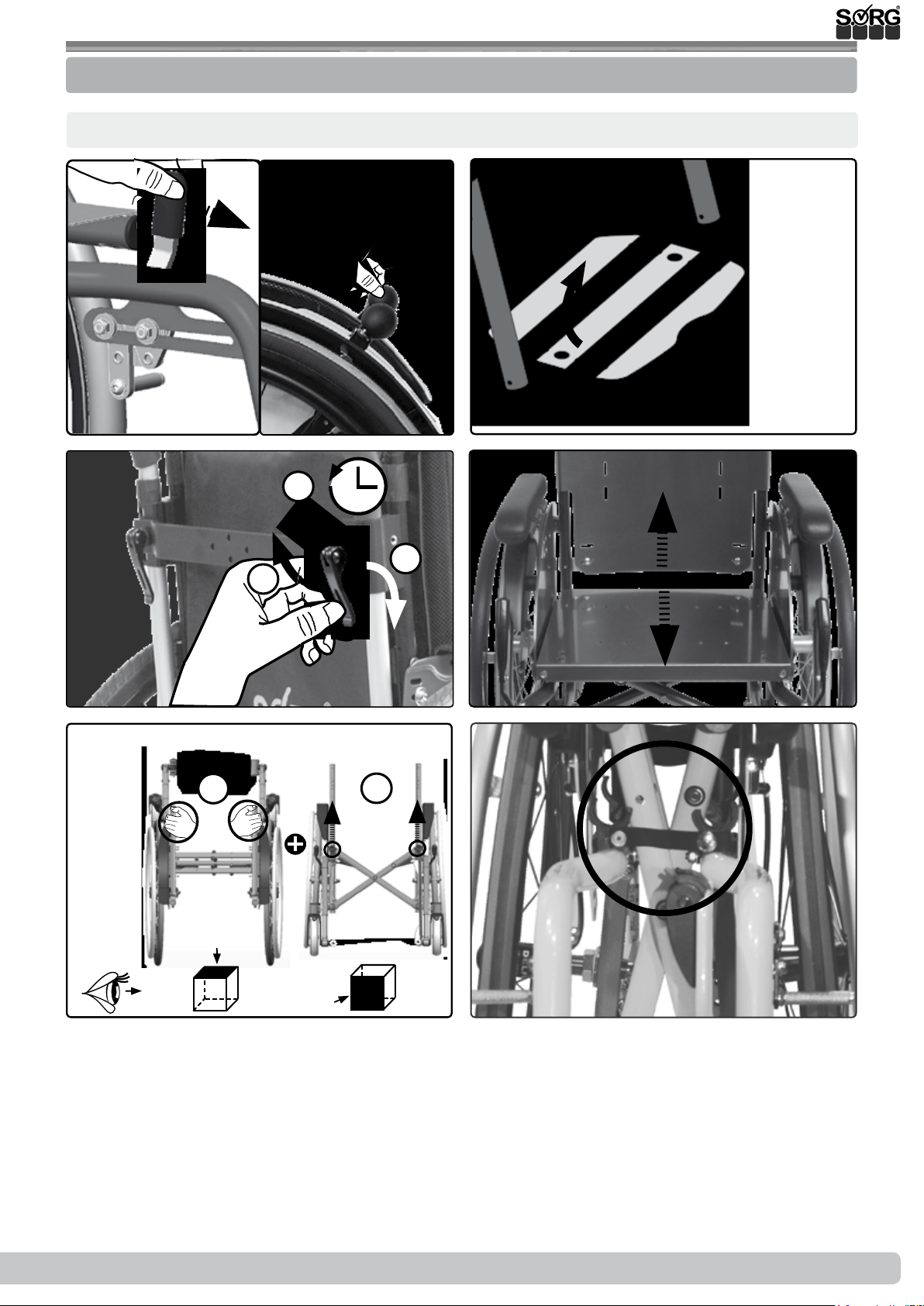
3.4 Handling folding up and unfolding
3.4.3 of SeatFix and/or rm curved back plate
Fold up (unfold: proceed accordingly in reverse order):
(1)
(1)
(3)
(2)
(4)
2.
3.
1.
(5)
1.
(6)
1.
2019-08-16
Instructions for use Jump alpha
25 of 48
Page 26
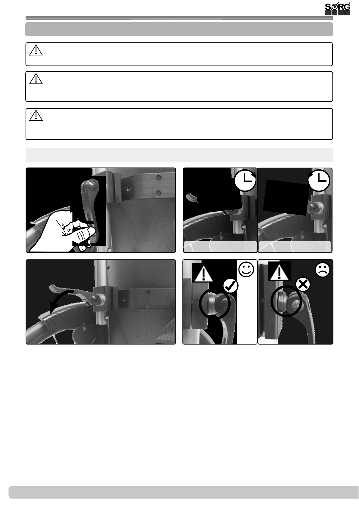
3.5 Handling pushing aid
3.5.1 General information regarding pushing aids
All height-adjustable pushing aids are designed exclusively to push the occupant in their
wheelchair - not to carry them.
Children are not able to competently judge the swivel range of protruding pushing aids
and may injure others while playing. We recommend folding back or dismantling the pushing
aids in such cases.
Check that the eccentric clamps are tightly closed and in good working order before each
use of the pushing aids. It must not be possible to move the pushing aids in the intake with
the eccentric clamp(s) in the closed position.
Set the eccentric clamp:
(1)
(3)
(2a)
Increase clamping force Reduce clamping force
(4a)
(2b)
(4b)
26 of 48
Instructions for use Jump alpha
2019-08-16
Page 27
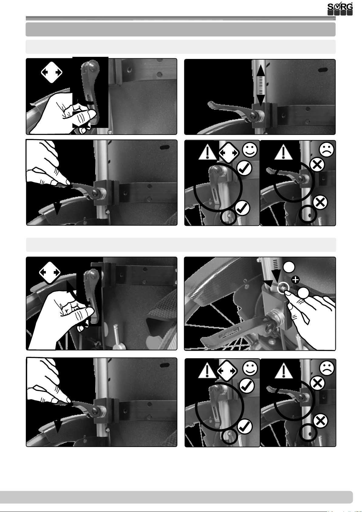
3.5 Handling pushing aid
3.5.2 Push handles
Set height:
(1)
(3)
2x
(2)
(4a)
2x
(4b)
Insert (remove: proceed accordingly in reverse order):
(1)
2x
(3)
(2)
(4a)
1.
1.
(4b)
2x
2019-08-16
Instructions for use Jump alpha
27 of 48
Page 28
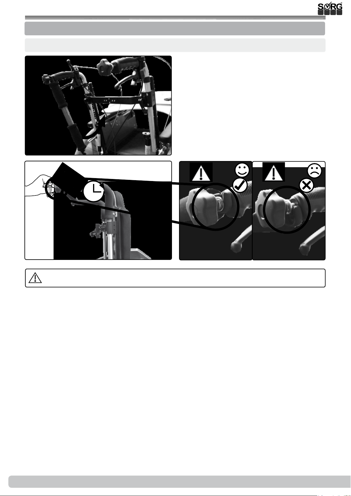
3.5 Handling pushing aid
3.5.3 Handle bar
Swivel up (swivel out: proceed accordingly in reverse order):
(1)
(2)
The handle bar is only intended for pushing, not for pulling or overcoming obstacles.
(3a)
(3b)
28 of 48
Instructions for use Jump alpha
2019-08-16
Page 29
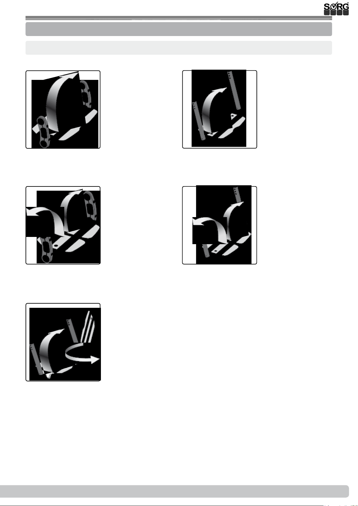
3.6 Handling leg support
3.6.1 General information regarding leg supports
Types of leg supports and their handling:
Model 1:
(1)
Model 3:
(3)
Model 2:
(2)
Model 4:
(4)
Model 5:
(5)
2019-08-16
Instructions for use Jump alpha
29 of 48
Page 30
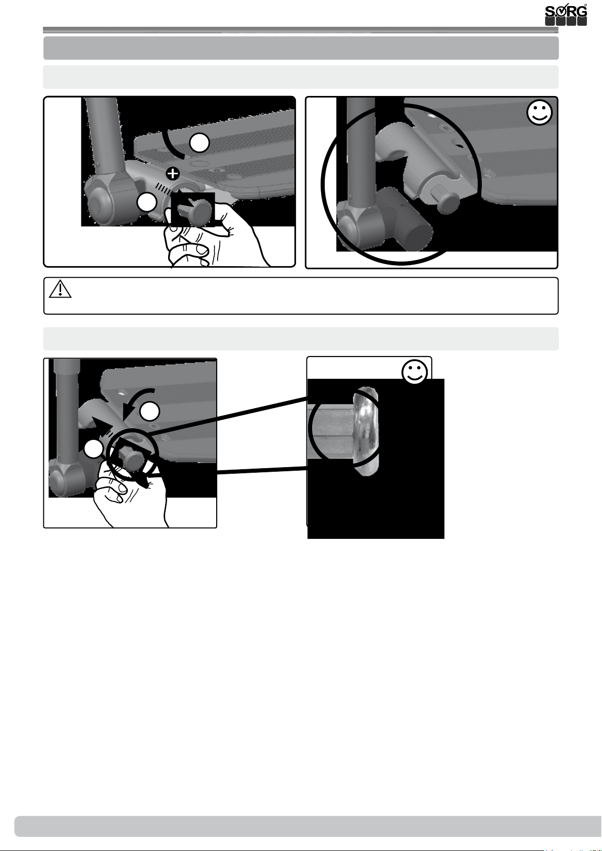
3.6 Handling leg support handling
3.6.2 Foldable footrest with locking mechanism
Unlock:
(1)
1.
1.
As the occupant, make sure that you do not lean too far out of the wheelchair when han-
dling the locking mechanism.
Lock:
(1)
(2)
(2)
2.
1.
30 of 48
Instructions for use Jump alpha
2019-08-16
Page 31
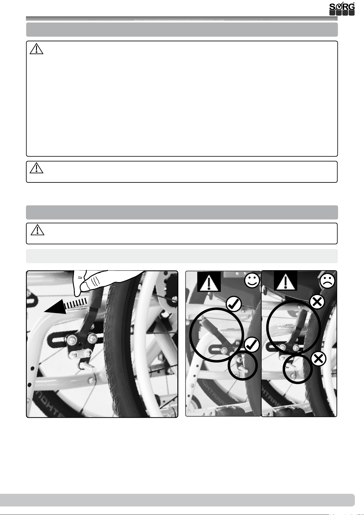
3.7 Handling brake
3.7.1 General information regarding brakes
Check that the brakes are in good working order before moving! Immediately contact
your dealer if the braking eect deteriorates.
Possible impairments or malfunctions may be caused by:
• contaminated or incorrectly adjusted brakes,
• defective cable controls,
• too large a distance between brake pressure bolt and tyres,
• insucient tyre ination pressure (information on the tyre casing),
• wetness, snow, mud etc..,
• worn treads,
• worn or contaminated brake pressure bolts.
The wheelchair cannot be used until the brakes have had any malfunctions rectied.
Always check that the brakes are locked securely and in working order on downhill
gradients.
3.7.2 Wheel lock
The knee lever and cable control brakes are wheel locks and are not suitable for slowing
down when moving.
Locking the wheel with the knee lever brake:
(1)
(2a)
(2b)
2019-08-16
Instructions for use Jump alpha
31 of 48
Page 32
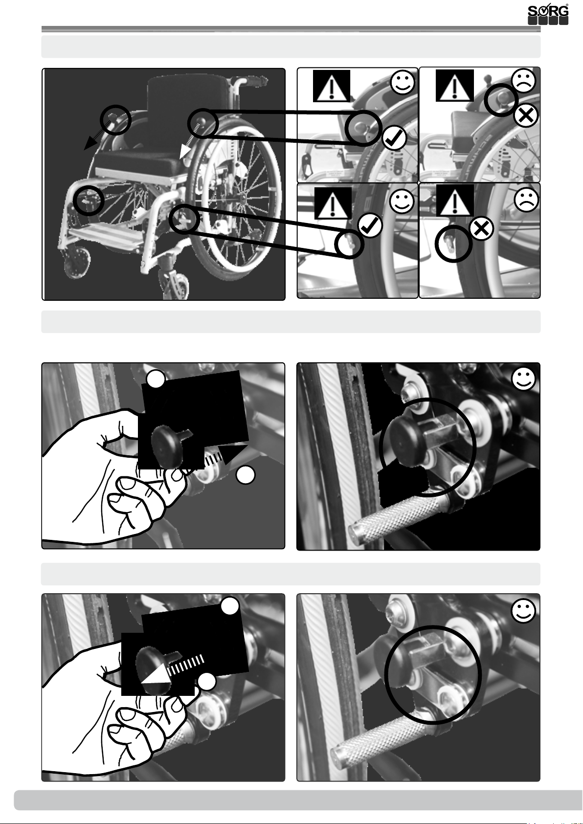
3.7 Handling brake
Locking the wheel with the cable control brake:
(1)
(2a)
(3a)
Locking in open or closed position:
First set the brake to the desired position (braked/unbraked).
(2b)
(3b)
(1)
Unlock:
(1)
1.
90°
90°
2.
(2)
2.
(2)
32 of 48
1.
Instructions for use Jump alpha
2019-08-16
Page 33
3.7 Handling brake
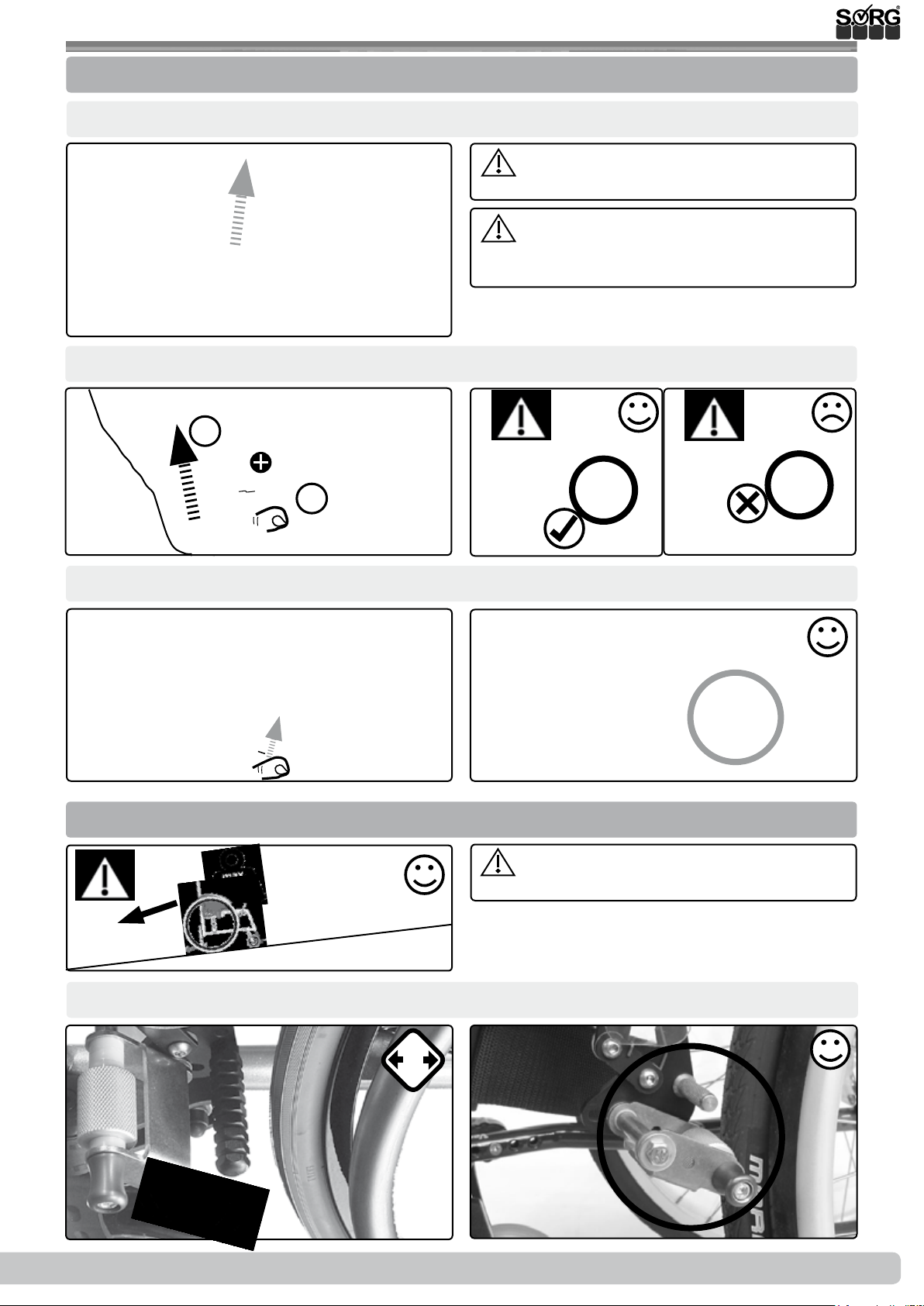
3.7.3 Drum brake
Slow down:
(1)
Lock:
(1)
Release:
1.
1.
Unequal use of both brake levers results
in cornering.
Clean the braking elements of the drum
brake wheels at short intervals using a soft
brush.
(2a)
(2b)
(1)
3.7.4 Reverse-roll locking
max 7°/ 12%
Activate (deactivate: proceed accordingly in reverse order):
(1)
2x
(2)
drives.
(2)
Not suitable in combination with auxiliary
2019-08-16
Instructions for use Jump alpha
33 of 48
Page 34
3.8 Handling anti-tipper
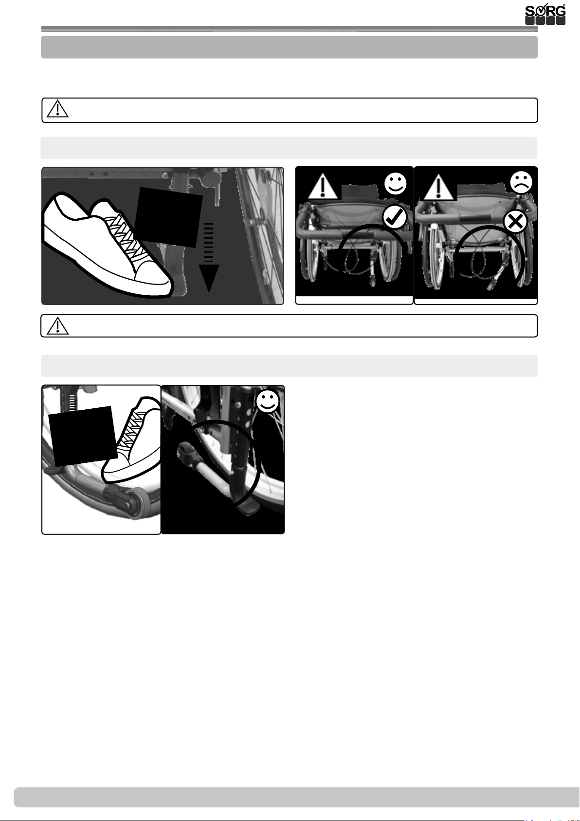
3.8.1 General information regarding anti-tipper
To improve tilting stability, a wheelbase extension, or at least an anti-tipper, must be used by
people who have had leg amputations.
A wheelbase extension is not a replacement for an anti-tipper.
Activate:
(1)
180°
The anti-tipper must always be locked in its end position.
Deactivate:
(1)
180°
(2)
(2)
Only rotate the anti-tipper 180° from deactivated position to active position. Avoid full revolutions in one direction, since otherwise the tension spring inside the anti-tipper will be damaged, which may result in the anti-tipper losing its functionality.
34 of 48
Instructions for use Jump alpha
2019-08-16
Page 35
3.9 Handling headrest
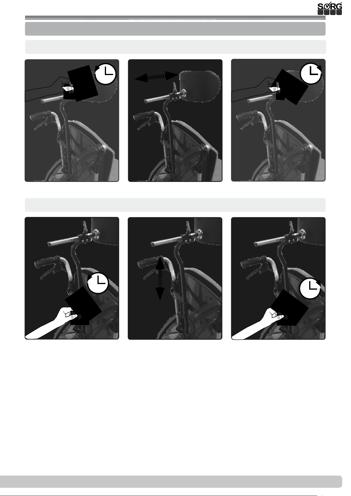
3.9.1 General information regarding headrest
Set distance:
(2)(1) (3)
Set height:
(1) (3)
(2)
2019-08-16
Instructions for use Jump alpha
35 of 48
Page 36
3.10 Handling abduction wedge
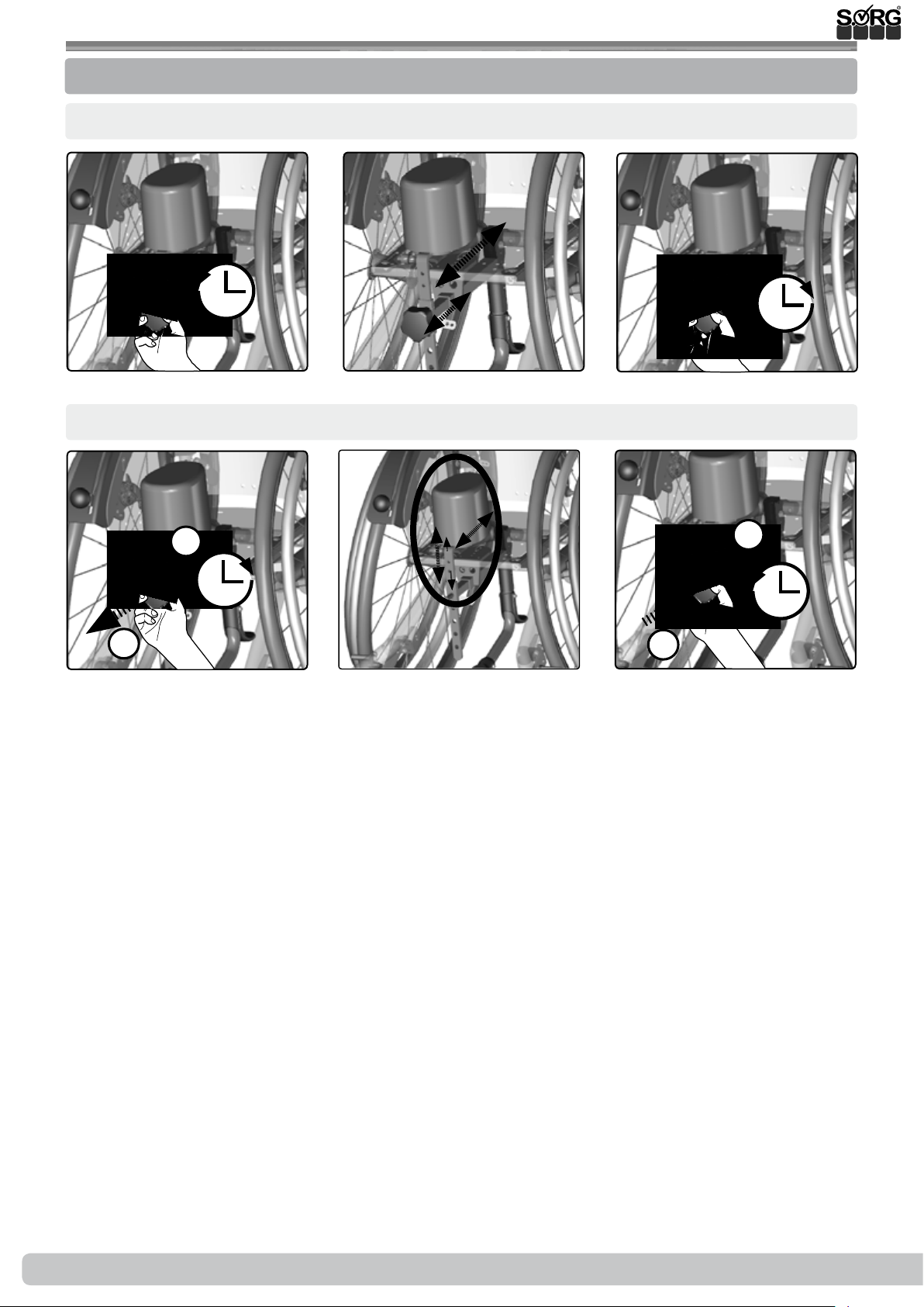
3.10.1 General information regarding abduction wedge
Set distance:
(1)
Set height:
(1)
1.
(2)
(2)
(3)
(3)
2.
2.
1.
36 of 48
Instructions for use Jump alpha
2019-08-16
Page 37
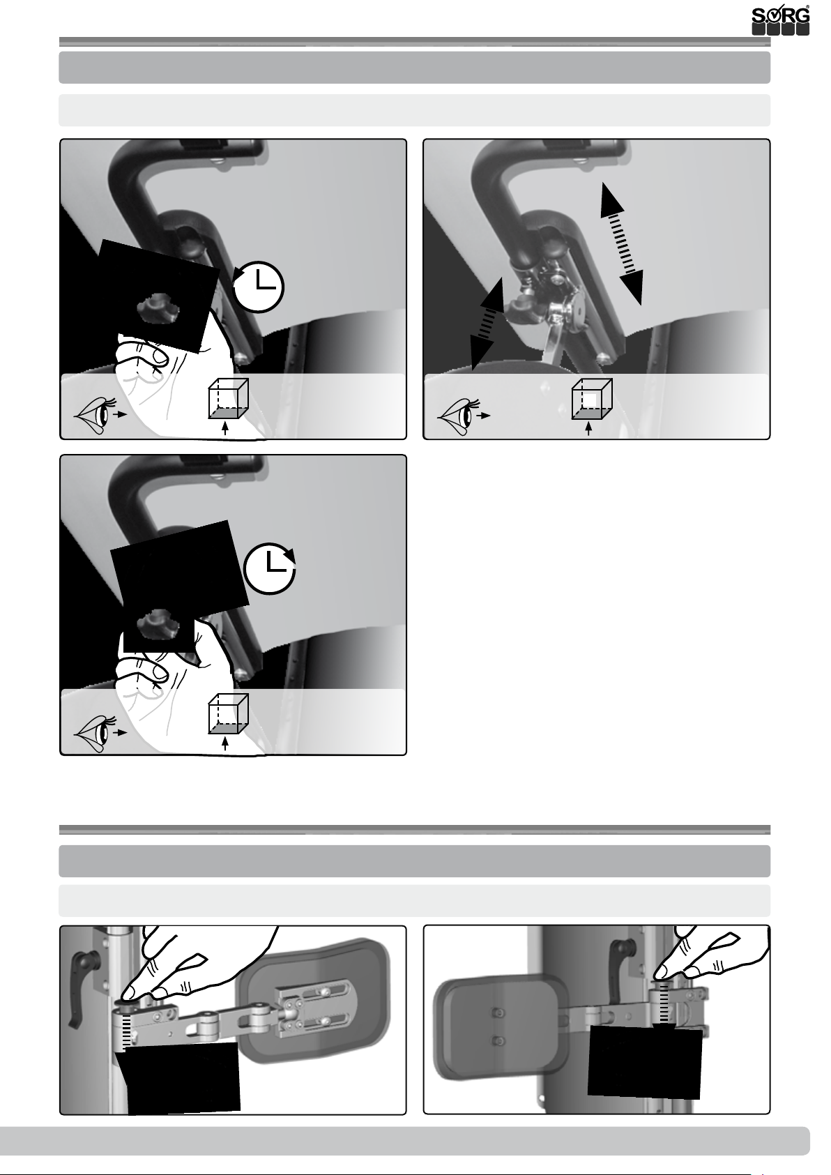
3.11 Handling therapy table
3.11.1 General information regarding therapy table
Set depth/ insert / remove:
(1) (2)
(3)
3.12 Handling lateral truss pad
3.12.1 General information regarding lateral truss pad
Open/close:
(1)
2019-08-16
(2)
Instructions for use Jump alpha
37 of 48
Page 38
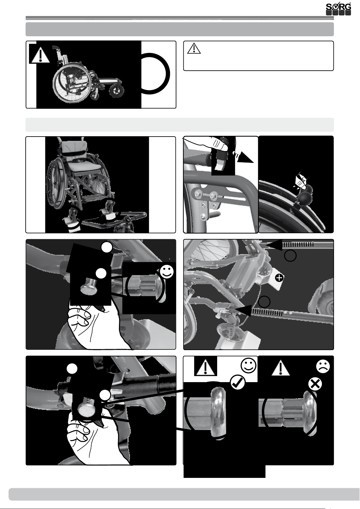
3.13 Handling steering & pushing aid
3.13.1 General information regarding steering and pushing aids
Pay attention to the max. load of the
max.
wheelchair, this also applies to the steering
and pushing aid.
8
km/h
Mount (dismount: proceed in reverse order at Fig. 4):
(1)
(3)
90°
1.
2.
(2)
(2)
(4)
1.
1.
(5)
38 of 48
1.
90°
2.
(6a)
Instructions for use Jump alpha
(6b)
2019-08-16
Page 39
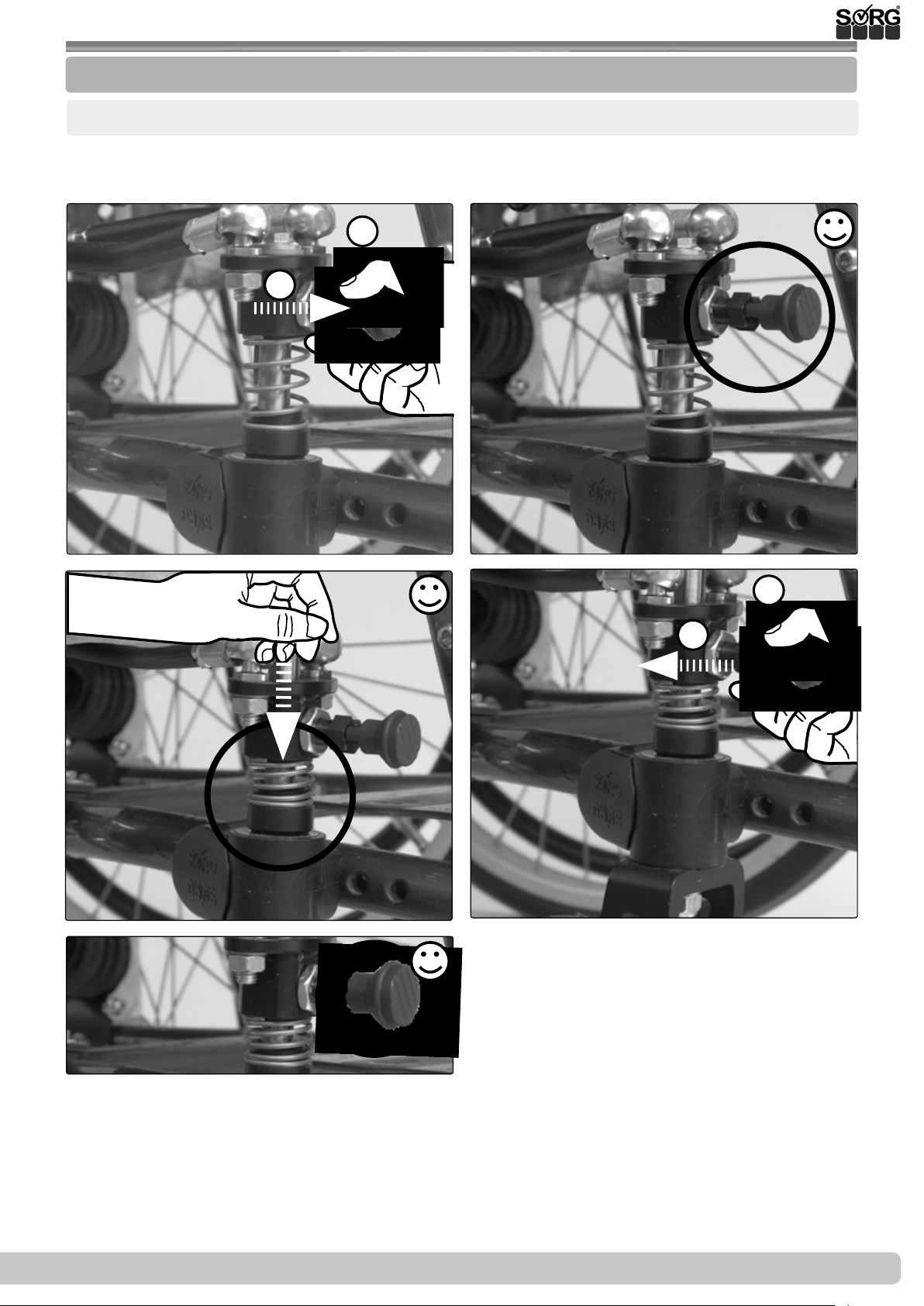
3.14 Handling one-hand steering aid
3.14.1 General information regarding one-hand steering aid
Activate (deactivate: proceed accordingly in reverse order):
The swivel casters must be set to the “straight ahead” position - this is the only way to activate
or deactivate one-hand steering.
(1)
(3)
1.
2.
90°
(2)
(4)
2.
1.
90°
(5)
2019-08-16
Instructions for use Jump alpha
39 of 48
Page 40
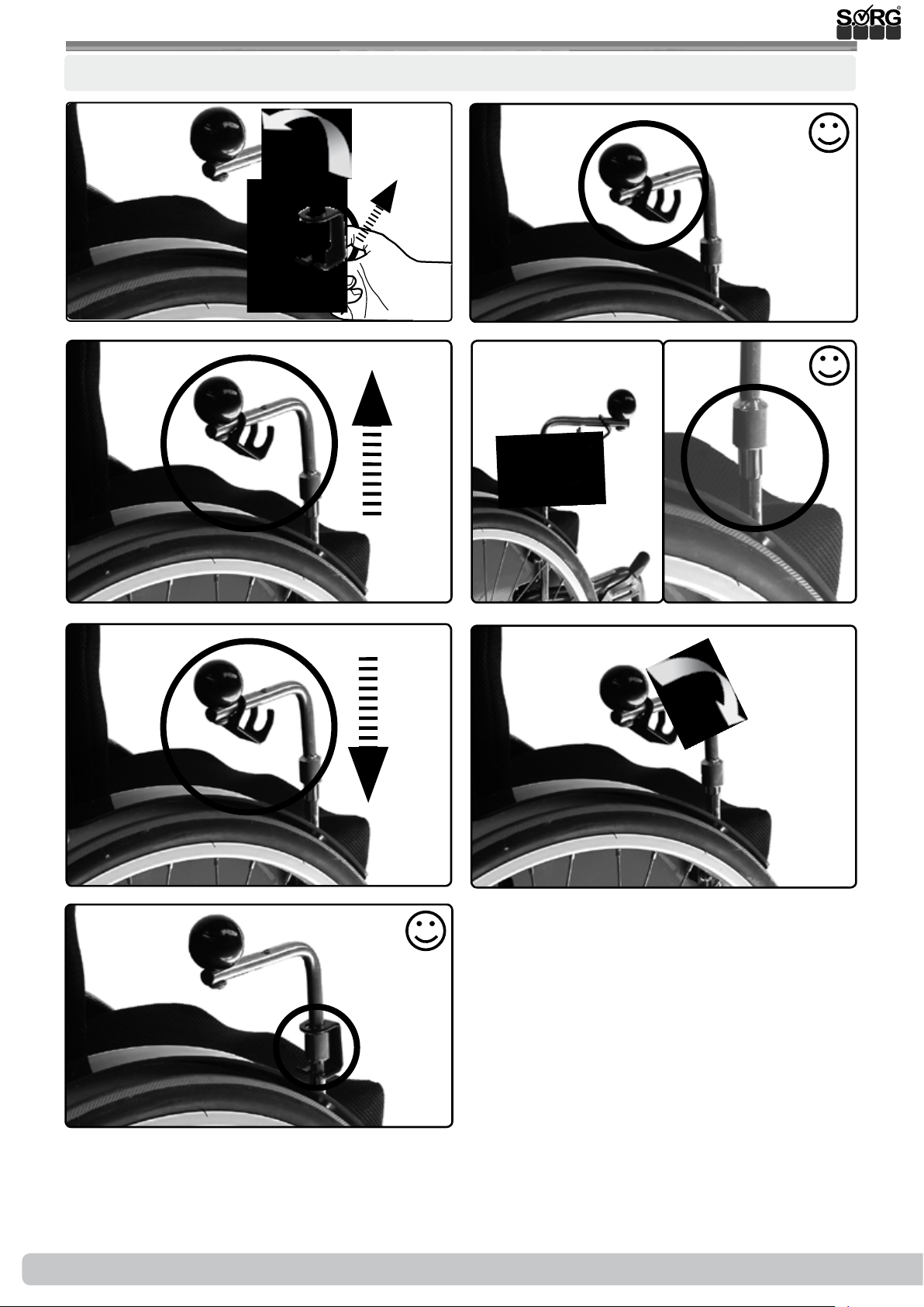
3.14 Handling one-hand steering aid
Set:
(1)
(3)
(2)
(4)
(5)
(7)
(6)
40 of 48
Instructions for use Jump alpha
2019-08-16
Page 41
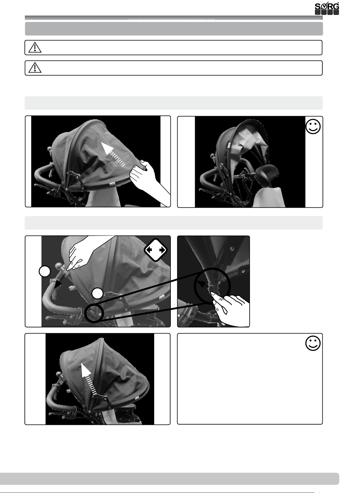
3.15 Handling sun shade
3.15.1 General information regarding sun shade
The sun shade can reach temperatures of over 42° when exposed to the sun.
Never carry the wheelchair over an obstacle using the sun shade.
It is not suitable for protection against rain.
Fold in (fold out: proceed accordingly in reverse order):
(1)
Detach (attach: proceed accordingly in reverse order):
(1)
2x
1.
(2)
(2)
2.
(3) (4)
2019-08-16
Instructions for use Jump alpha
41 of 48
Page 42
4 Repairs and maintenance
4.1 Repairs
Repairs must only be carried out by a specialist dealer.
4.2 Spare parts
Only original replacement parts may be used. These can be obtained from your specialist dealer.
The replacement parts list can be downloaded from www.sorgrollstuhltechnik.de or re-
quested from us.
Please indicate the serial number of your wheelchair to ensure correct replacement part delivery.
This can be found on the nameplate on the frame.
4.3 Maintenance
Regularly clean the wheelchair and all components using a mild, water-based household detergent and then dry thoroughly.
Also clean the driving and swivel casters and remove dirt and impurities (e.g. hair etc.) from the
axles.
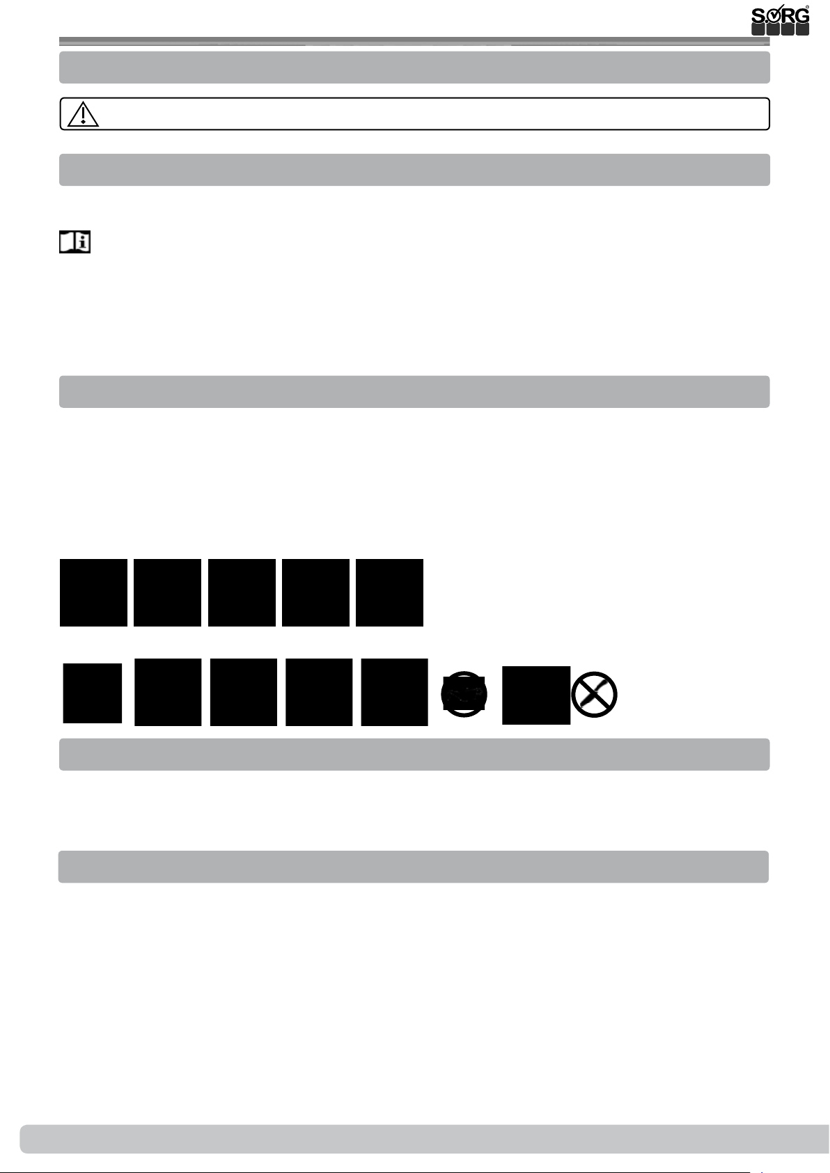
Washing textile parts:
Care instructions:
Wipe down imitation leather, belts and other upholstery:
Care instructions:
4.4 Disinfection
Cleaning must be carried out before each disinfection. Use a household water-based agent for
disinfection. Please observe the application instructions of the respective manufacturer.
4.5 Storage
42 of 48
• Carry out cleaning
• Fold up foldable wheelchair (if applicable)
• Set (seating unit) tilt mechanism (if present) to 90°.
• Pack detachable textile parts in foil or the like, if necessary
• Secure the wheelchair against rolling away and contamination
• Storage in a dry place without aggressive environmental inuences
Instructions for use Jump alpha
2019-08-16
Page 43
4 Repairs and maintenance
4.6 Reinstatement
A complete inspection by a qualied specialist dealer must be carried out in accordance with
the checklist prior to reuse. All disinfection measures for reuse must be carried out in accordance with a validated hygiene plan.
4.7 Disposal
The wheelchair must only be disposed of with the permission of the health insurance company.
The wheelchair must be disposed of in accordance with the respectively applicable national legal
regulations.
4.8 Maintenance/ inspection
An inspection must be carried out by your specialist dealer at least once a year for safety reasons and to preserve the product warranty. This must be carried out and documented in accordance with the following checklist.
Maintenance and care checklist (user)
Unsatisfactory or neglected maintenance of the wheelchair poses a considerable
safety risk.
Before each use:
Check:
• the frame, back tubes, add-on parts and accessories for visible damage, bending, cracks
or missing or loose screws,
• the wheels and quick-release axles for tightness,
• that the ination pressure and tyre tread are sucient,
• that the brakes are working properly,
• that the angle adjustment elements/ eccentric clamps are secure,
• that the seat plate/ back/ footrest are tightly locked,
• that the anti-tipper/seat and back belts are functioning correctly,
• that all previously dismantled components have been reconnected and rmly locked.
Every 3 months:
(or even earlier depending on performance)
Check:
• screw connections for tightness,
• Welding seams, add-on parts and accessories for hidden damage, bends or cracks,
• tyre tread,
• the tightness of external systems (if present).
Thoroughly clean and oil all moving parts.
Please contact your dealer immediately if you notice any defects during maintenance.
Stop using the wheelchair.
2019-08-16
Instructions for use Jump alpha
43 of 48
Page 44
4 Repairs and maintenance
Annual inspection checklist (specialist dealers)
Copy template (available for download at www.sorgrollstuhltechnik.de/downloadportal)
Preparation:
Cleaning carried out
Check:
Frame, back unit, add-on parts and accessories checked for damage,
bending, cracks and corrosion,
Attachment screws checked for completeness and tight t,
Wheels and casters as well as the corresponding add-on parts checked for condition,
functionality
and running characteristics,
Spokes checked for tight t and completeness,
Brakes cleaned and serviced,
Locking mechanisms (springs of the push handles, quick-release axles, eccentric clamps, etc.)
checked for functionality,
Antitipper checked for secure t and functionality.
Oil:
Moving parts and bearings oiled
Final check:
Functional check of all mechanical adjustment devices carried out
44 of 48
Instructions for use Jump alpha
2019-08-16
Page 45
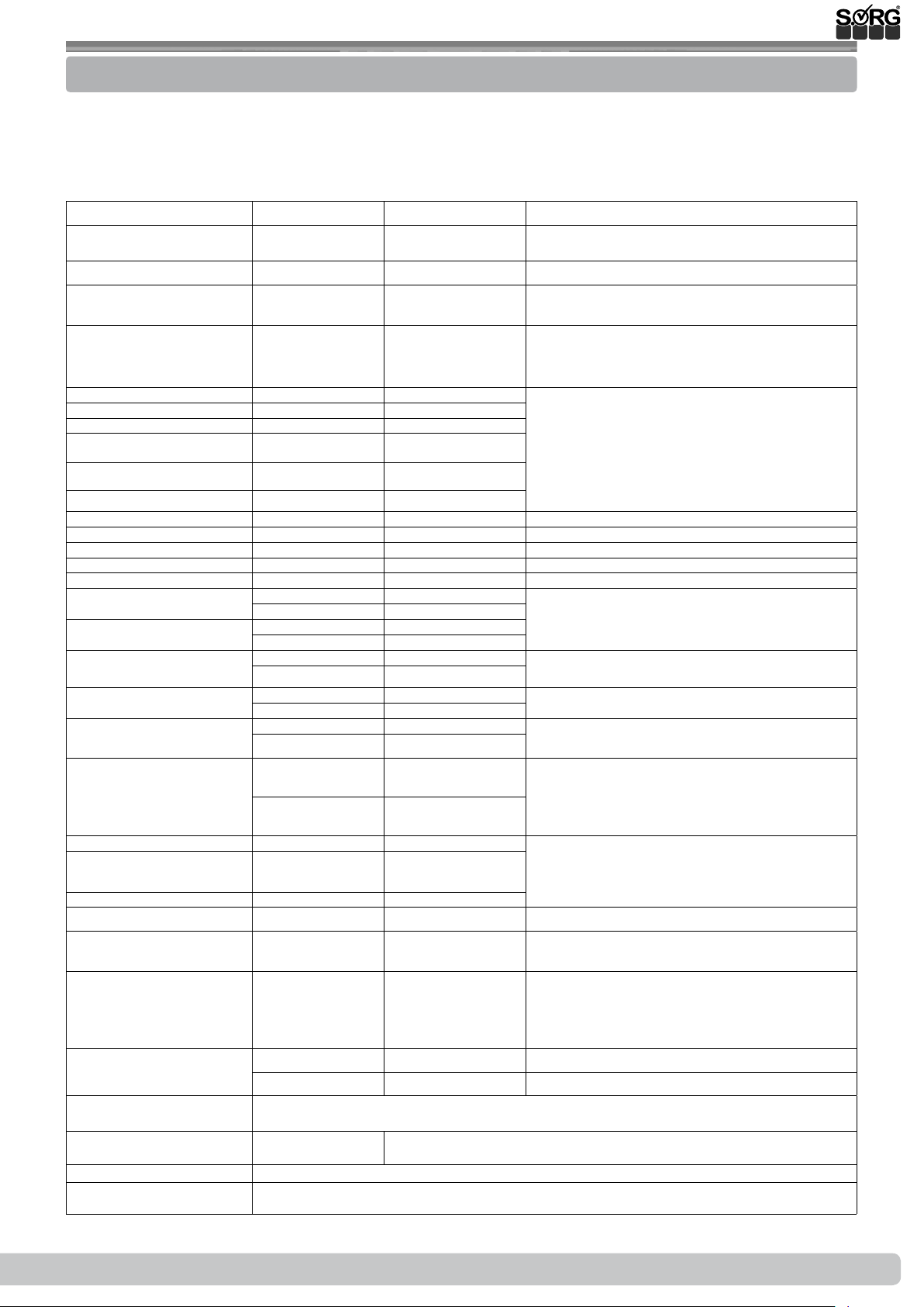
5 Technical data
5.1 Data and measurements
Model: Jump alpha
Type: 485
Aid index no.: 18.50.03.1079
All measurements ± 5%
Designation Dimensions Remarks
Seat width (SW)
in 20 mm increments
Seat depth (SD) 260-380 mm optional per SD + max. 40 mm growable
Back height (BH)
in 25 mm increments
Upper edge (UE) seat to
upper edge (UE) footrest
Frame length 1 504 mm
Frame size 2 529 mm
Frame size 3 549 mm
ETRTO wheel size at 20" Ø 451 mm Conventional pneumatic tyres in sizes 1"
ETRTO wheel size at 22" Ø 489 mm
ETRTO wheel size at 24" Ø 540 mm
Handrim size at 20" Ø max. 444 mm
Handrim size at 22" Ø max. 481 mm
Handrim size at 24" Ø max. 533 mm
Handrim diameter Ø 19 mm Tube diameter
Camber 2°, 5°, 8°
Seat height (SH) front min. 395 mm The seat heights are measured from the upper
Seat height (SH) rear min. 340 mm
Width wheelchair absolute
Width wheelchair folded min. 290 mm
Length wheelchair absolute
Height wheelchair absolute
Permissible incline 12.3% = 7°
Permissible downward
gradient
Resistance to tilting 12.3% = 7°
Turn radius approx. 1000 mm dependent on the wheelchair size
Load (max.)/ weight test
dummy
Empty weight min. t for use = SW
Individual weights Driving wheels 1.2 – 2 kg per unit depending on size and design
Tyres Conventional pneumatic tyres, sizes 1" or 1 3/8" or puncture-proof tyres
Usage life of the wheelchair
Service life 5 years
Normative requirements The wheelchair complies with the requirements of ISO 7176-8 and the requirements
Indoor attachment
Outdoor attachment
max. 500 mm
max. 495 mm
min. SW + 200 mm For smallest or largest camber
max. SW + 380 mm
max. 350 mm
min. 620 mm With steering and pushing aid correspondingly
max. 1080 mm
with push handles
Standard
with push handles
height-adjustable
max. 75 kg
240, SD 260 mm,
20" wheels, 4" PU
swivel casters
Frame 8 kg
(same dimensions), tyre pressure usually 3-10 bar
3 years in case of non-excessive strain
against ignition.
240-380 mm optional per SW + max. 20 mm growable
250-450 mm growable by 25 / 50 mm
25 - 300 mm
300 - 460 mm
min. 620 mm
max. 1480 mm
12.3% = 7°
9.25 kg Frame, side guard, driving and caster wheels, leg
The lower leg length (LLL) is the distance from:
UE seat to UE footrest PLUS thickness of the seat
cushion.
(25.4 mm), 1 3/8" (35 mm) - sizes 489 mm
(22"), 540 mm (24"), 590 mm, (26"). All punc-
tureproof tyres in the specied dimensions.
edge of the seat to the oor, WITHOUT seat
cushions!
more.
supports, back and seat cover
2019-08-16
Instructions for use Jump alpha
45 of 48
Page 46
5 Technical data
5.2 Meaning of labels
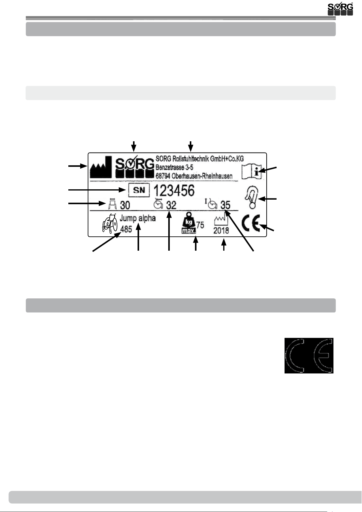
The meaning of the individual labels can be directly derived from the text at the corresponding
position.
A new nameplate can be obtained from SORG Rollstuhltechnik if the original one is lost or damaged.
Type plate:
Manufacturer logo Manufacturer address
Reference to
manufacturer
Serial number
Seat width
Type number
( )
Model name
Seat depth
Maximum
load
Year of
construction
Back height
Reference to
product literature
Reference to Crash
Test in accordance
with ISO 7176-19
CE mark
5.3 Declaration of conformity
SORG Rollstuhltechnik hereby declares that the Jump alpha product is a Class 1 device and complies with the applicable provisions of EC Directive 93/42/EEC Annex VII on medical devices.
This was veried by a conformity assessment procedure in accordance with the
Medical Devices Directive Annex VII.
This declaration shall lose its validity if the product is modied without the
consent of SORG Rollstuhltechnik.
46 of 48
Instructions for use Jump alpha
2019-08-16
Page 47
6 Verication of yearly inspection
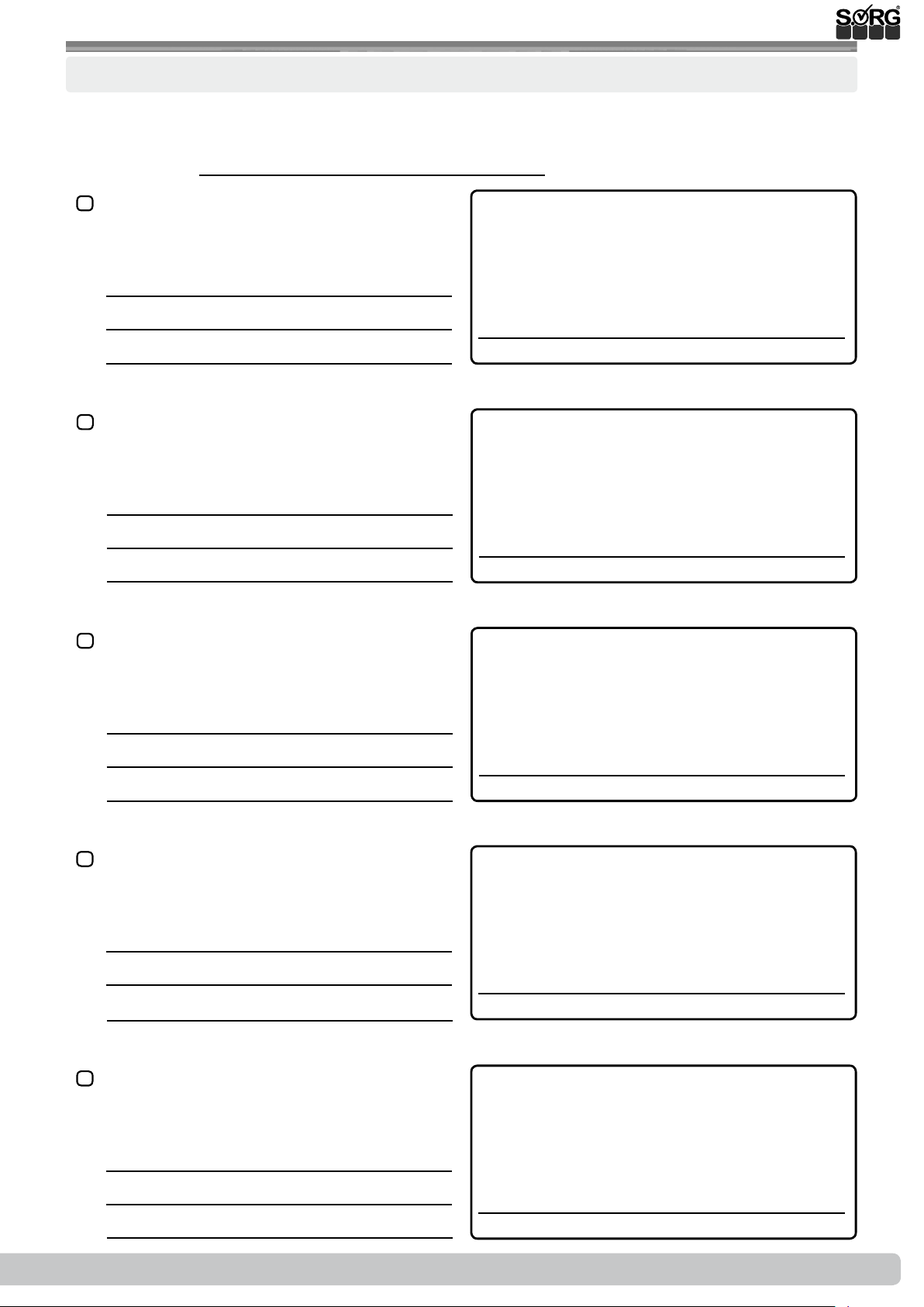
Documentation yearly inspection
An inspection must be carried out by your specialist dealer at least once a year for safety reasons and to preserve the product warranty.
Serial number:
yearly inspection conducted according to
check list (operating year 1)
Remarks:
yearly inspection conducted according to
check list (operating year 2)
Remarks:
yearly inspection conducted according to
check list (operating year 3)
Stamp:
Date/ Retailer's signature
Stamp:
Date/ Retailer's signature
Stamp:
Remarks:
yearly inspection conducted according to
check list (operating year 4)
Remarks:
yearly inspection conducted according to
check list (operating year 5)
Remarks:
Date/ Retailer's signature
Stamp:
Date/ Retailer's signature
Stamp:
2019-08-16
Date/ Retailer's signature
Instructions for use Jump alpha
47 of 48
Page 48
Jump alpha Instructions for use
Company stamp
SORG Rollstuhltechnik GmbH + Co. KG
Benzstrasse 3-5
68794 Oberhausen-Rheinhausen / Germany
Germany
Phone +49 7254 9279-0
Fax +49 7254 9279-10
www.sorgrollstuhltechnik.de
 Loading...