

Page 1
SAVE THESE INSTRUCTIONS
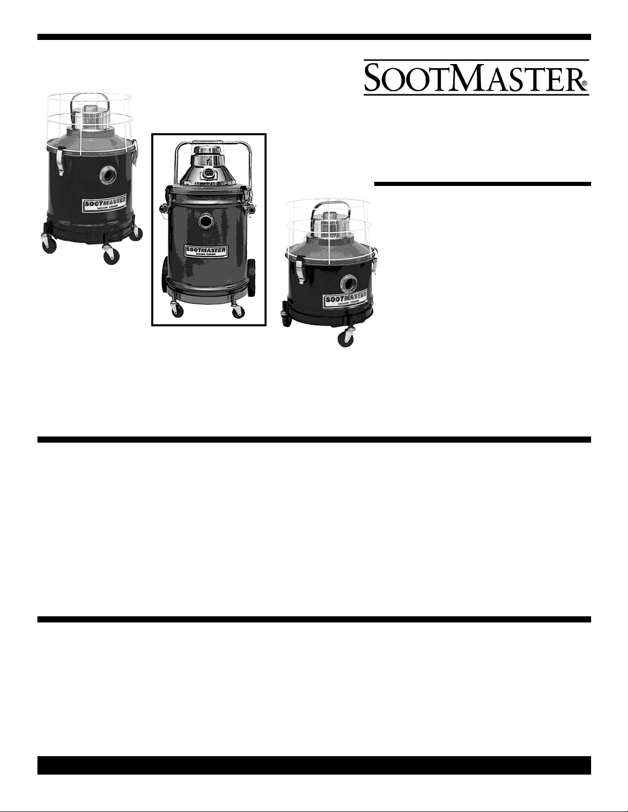
FURNACE DRY
VACUUM CLEANERS
SAFETY, OPERATION
& MAINTENANCE
MANUAL
/PARTS LIST
W
This unit is intended for commercial Use.
READ AND FOLLOW ALL INSTRUCTIONS,
ARNINGS & CAUTIONS BEFORE USING THIS
W
VACUUM CLEANER
This vacuum cleaner will afford you
many years of trouble-free operating
satisfaction, provided it is given proper
care. All parts have passed rigid quality
control standards prior to being assembled to produce the finished product.
Prior to packaging, the vacuum was
again inspected for assurance of flawless assembly.
Your vacuum is protectively packed to
prevent damage in shipment. We recommend that upon delivery, unpack the
vacuum and inspect it for any possible
Treat this vacuum as you would any
other high grade precision made product. Dropping, unreasonable bumping
across thresholds and other misuses
may result in a damaged unit which will
not be covered by warranty.
damage. Only a visual examination will
reveal damage that may have occurred.
If damage is discovered, immediately
notify the transportation company that
delivered your vacuum. As a shipper, we
are unable to report claims for concealed damage. You must originate any
claims within 5 days.
This manual is for your protection and
information. PLEASE READ CAREFUL-
LY since failure to follow precautions
could result in discomfort or injury.
Read this manual completely before
operating the vacuum. It is important to
follow instructions in this manual to prevent the possibility of injury or damage
to the user and/or vacuum.
PLEASE READ
CAREFULLY
BEFORE
OPERATING
CARE OF THIS
VACUUM CLEANER
When not in use, power cord should be
wrapped around the motor head for storage.
PAGE 1
Sootmaster Manual - PN 376566 Rev G - Printed in USA 03/09/05
Page 2
IMPORTANT
SAFETY
INSTRUCTIONS
When using this electric vacuum, basic precautions should always be followed, including the following:
WARNING
To Reduce the Risk of Fire, Electric Shock or Injury:
Dry Vacuums
Electric shock could occur if used on wet surfaces.
DO NOT expose to rain - Store Indoors
1) DO NOT leave the vacuum when
plugged in. Unplug it from the outlet
when not in use and before servicing.
2) This is NOT a toy. Close attention is
necessary when used around or near
children.
3. Use only as described in this safety
manual. Use only manufacturer’s recommended attachments and accessories.
4) DO NOT use this vacuum with damaged cord or plug. If the vacuum is not
working as it should, because it has been
dropped, damaged, left outdoors or
dropped into water, contact an authorized
service center or factory.
5) DO NOT pull the vacuum by the cord,
use cord as a handle, close a door on the
cord or pull cord around sharp edges and
corners. DO NOT run the vacuum over
the cord. Keep cord away from heated
surfaces.
6) DO NOT handle the vacuum plug or
the vacuum with wet hands.
7. DO NOT unplug the vacuum by pulling
on the cord. To unplug, grasp the plug,
not the cord.
8. DO NOT put any objects into openings. DO NOT use with any openings
blocked; keep free of dust, lint, hair, and
anything that may reduce air flow.
9) Keep hair, loose clothing, fingers, and
all parts of body away from the openings
and moving parts.
10) DO NOT pick up anything that is
smoking or burning such as cigarettes,
matches, or hot ashes.
11) DO NOT use without dust bag
and/or filters in place.
12) Turn OFF all the controls before
unplugging.
13) DO NOT use where anesthetics or
oxygen is used.
14) Use extra care when cleaning on
stairs.
15) DO NOT use this vacuum to pick up
flammable or combustible liquids such
as gasoline or use in areas where they
may be present.
16) Replace damaged or worn parts
immediately with genuine original equipment parts to maintain safety and to protect your limited warranty.
17) DO NOT use an extension cord
unless absolutely necessary. If an extension cord is used, then the wire size must
be #14 gauge or larger and should not
exceed 50 feet in length. The extension
cord must be three-wire type to insure
GROUNDING protection.
This vacuum must be connected to a
properly grounded outlet only. See
grounding instructions below. If your vacuum has an outlet for a motorized power
nozzle, always turn it OFF before connecting or disconnecting the motorized nozzle.
Improper use of the grounding plug can result in a risk of electric shock.
GROUNDING INSTRUCTIONS
Electrical equipment must be grounded. If it
should malfunction or breakdown, grounding
provides a path of least resistance for electrical current to reduce the risk of electric shock.
This vacuum is equipped with a cord having an
equipment-grounding conductor and grounding
plug. The plug must be inserted into an appropriate outlet that is properly installed and
ROUNDING METHODS
G
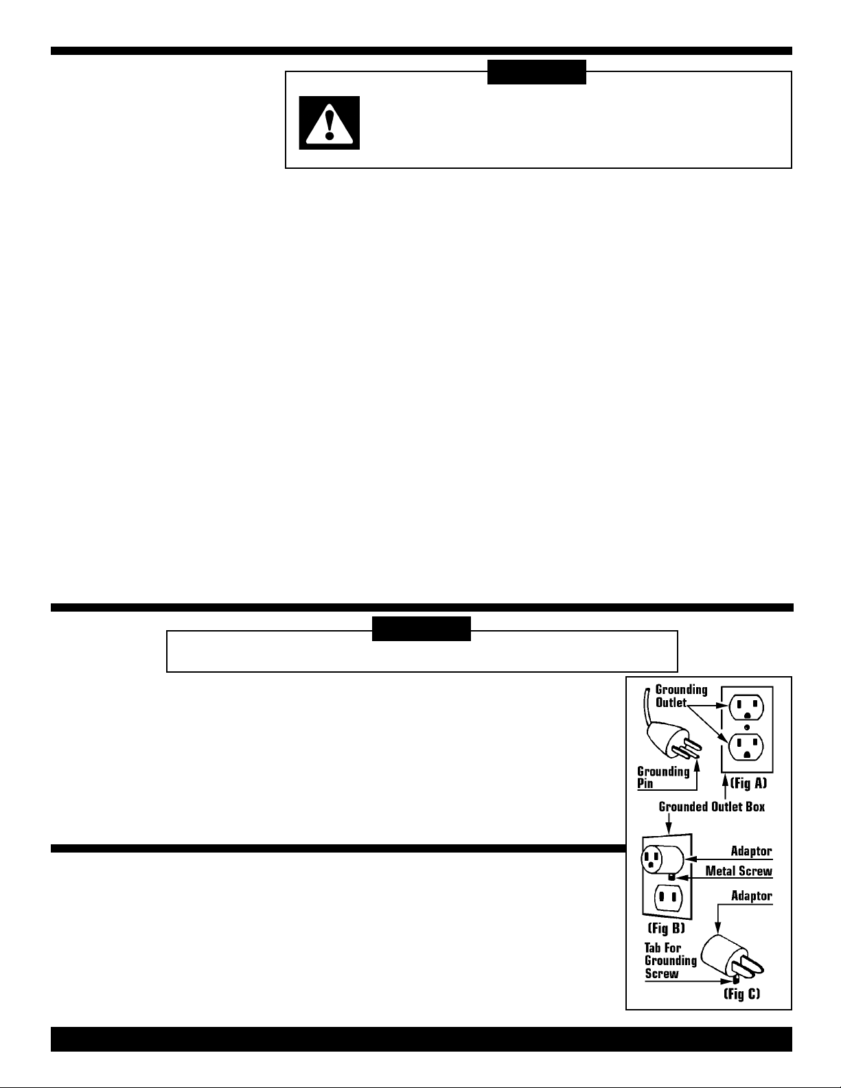
This electric equipment is for use on a nominal 120 volt circuit, and has a grounded plug
that looks like the plug illustrated in (Fig A). A
temporary adaptor that looks like the adaptor
illustrated in (Fig B & C) may be used to connect this plug to a 2-pole receptacle as
shown in (Fig B) if a properly grounded outlet
is not available.
DANGER
grounded in accordance with all local codes
and ordinances.
If repair or replacement of the cord or plug is
necessary, DO NOT connect the grounded
wire to either flat blade terminal. The wire
with insulation having an outer surface that is
green with or without yellow stripes is the
grounding wire.
The temporary adaptor should be used only
until a properly grounded outlet (Fig A) can be
installed by a qualified electrician. The green
color rigid ear, lug or the like extending from
the adaptor must be connected to a permanent ground such as a properly grounded
outlet box cover. Whenever the adaptor is
used, it must be held in place by a metal
screw. (Fig C)
PAGE 2
Page 3
WARNING
Improper connection of the equipment-grounding conductor can result in risk of electric shock. Check with qualified
electrician or service person if you are in doubt as to whether the outlet is properly grounded.DO NOT modify the
plug provided with the equipment. If it will not fit the outlet, have a proper outlet installed by a qualified electrician.
Note: In Canada, the use of a temporary adaptor is not permitted by the Canadian Electrical Code.
LIRE TOUTES LES INSTRUCTIONS AVANT DE FAIRE
FONCTIONNER (CET APPAREIL)
AVERTISSEMENT:
Pour reduire les risques d'incendie, de choc electrique ou de blessure:
POUR APPAREIL SEC
Pour réduire les risques de choc électrique, ne pas aspirer de maitières humides,
ne pas exposer à la pluie et garder l'aspirateur à l'intérieur.
L'utilisation d'un appareil électrique demande certaines précautions:
1. Ne pas laisser l'appareil sans surveillance lorsqu'il est branché. Débrancher
lorsque l'appareil n'est pas utilise ét avant
l'entretien.
2. Ne pas permettre aux enfants de jouer
avec l'appareil. Une attention particulière
est nécessaire lorsque l'appareil xest utilisé par des enfants ou à proximité de ces
derniers.
3. N'utiliser que conformément à cette
notice avec les accessoires recommandés par le fabricant.
4. Ne pas utiliser si le cordon ou la fiche
est endommagé. Retourner l'appareil à
un atelier de réparation s'il ne fonctionne pas bien, s'il est tombé ou s'il a
été endommagé, oublié à l'extérieur ou
immergé.
5. Ne pas apsirer de matières en combusion ou qui dégagent de la fumée,
comme des cigarettes, des allumettes
ou des cendres chaudes.
6. Ne pas tirer, soulever ou traîner l'appareil par le cordon. Ne pas utiliser le
cordon comme une poignée, le coincer
dans l'embrasure d'une porte ou l'appuyer contre des arêtes vives ou des coins.
Ne pas faire rouler l'appareil sur le cordon. Garder le cordon à l'écarte des surfaces chaudes.
7. Ne pas débrancher en tirant sur le
cordon. Tirer plutôt la fiche.
8. Ne pas toucher la fiche ou l'appareil
lorsque vos mains sont humides.
9. N'insérer aucun objet dans les ouvertures. Ne pas utiliser l'appareil lorsqu'une
ouverture est bloquée. S'assurer que de
la poussière, de la peluche, des cheveux
ou d'autres matières ne réduisent pas le
débit d'air.
10. Ne pas utiliser l'appareil si le sac à
poussière ou le filtre n'est pas en place.
NSTRUCTIONS VISANT LA MISE À LA TERRE
I
11. Maintenir les cheveux, les vêtements amples, les doigts et toutes les
parties du corps à l'écart des ouvertures et des pièces mobiles.
12. Mettre toutes les commandes à la
position ARRET avant dé debrancher
l'appareil.
13. User de prudence lors du nettoyage
des escaliers.
14. Ne pas aspirer des liquides inflammables ou combustibles, comme de
l'essence, et ne pas faire fonctionner
dans des endroits où peuvent se trouver
de tels liquides.
15. Toujours mettre l’interruptuer de
l’appariel à la position ARRET avant de
brancher ou de débrancher la brosse à
moteur.
16. Ne brancher qu'à une prise de
courant avec mise àla terre. Voir les
instructions visant la mise à la terre.
Cet appareil doit être mis à la terre. En
cas dé défaillance ou de panne
éventuelles, la mise à la terre fournit au
courant un chemin de moindre résistance qui réduit le risque de choc élec-
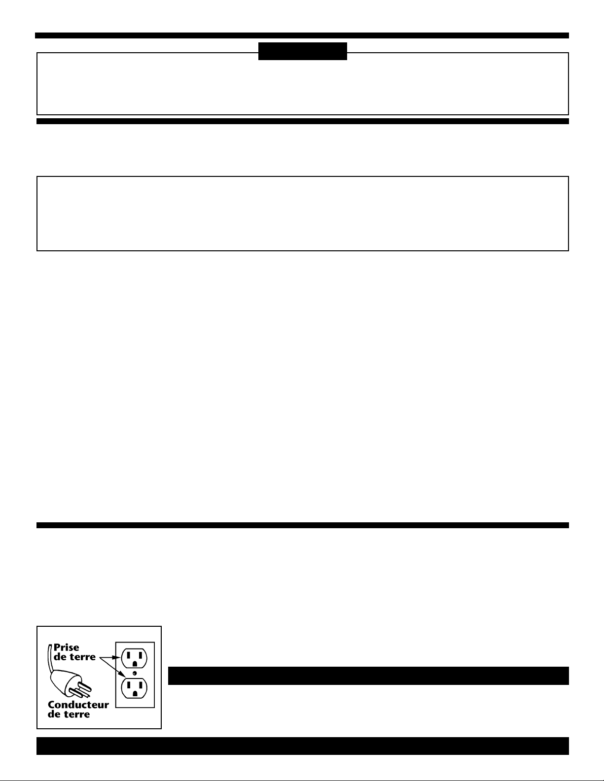
Cet appareil est destiné à un circuit de 120V et
est muni d'une fiche de mise à la terre semblable à celle illustrée par le croquis A de la figure "A". S'assurer que l'appareil est branché à
Un conducteur de terre mal raccordé peut
entraîner un risque de choc électrique.
Consulter un électricien ou un technicien d'entretien qualifié si vous n'êtes pas certain que la
trique. Cet appareil est pourvu d'un cordon muni d'un conducteur de terre et
d'une fiche avec broche de terre. La
fiche doit être branchée dans une prise
appropriée correctement instalée et
une prise de courant ayant la même configuration que la fiche. Aucun adaptatteur ne devrait
être utilisé avec cet appareil.
AVERTISSEMENT
prise soit correctement mise à la terre. Ne pas
modifier la fiche fournie avec l'appareilsi elle ne
peut être inséreé dans la prise, faire installer
une prise adéquate par un électricien qualifié.
PAGE 3
mise à la terre conformément aux
règlements et ordonnances municipaux.
Page 4
VACUUM ASSEMBLY
3 & 4
Caster
Vacuums
These vacuums
require some
assembly.
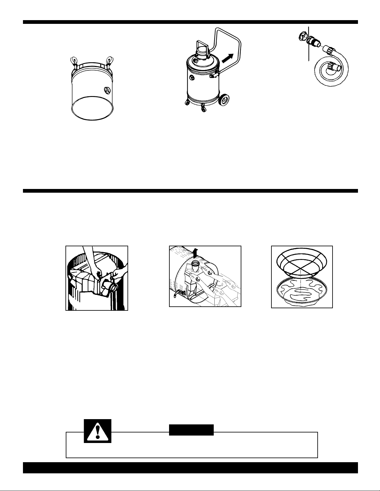
1) Carefully remove and set aside the
motor head and filter assembly.
2) Turn the canister upside down.
Insert casters into caster mount
assemblies and press down to lock in
position.
Glidemobile
w/Handle
Vacuums
The vacuum's
handle is in the
storage position when shipped and
must be moved to the operating position.
1) Firmly grasp the speed pins on each
side of the handle and pull up and out.
2) Pull handle slowly away from tank
and align front handle holes in handle
bracket.
FILTER INSTALLATION,
EMOVAL AND MAINTENANCE
R
The Sootmaster vacuums are designed for dry pickup. The 660M and 661M can be
converted to a wet vacuum providing you use the optional wet pickup adaptor (305987).
3) Insert speed
pins through holes
on both sides,
locking handle in position.
Hose & Swivel Connector
The hose and swivel connectorare preassembled at the factory and attaches
to the canister intake.
1) Line up the swivel connector slots
with the retaining rivets on the intake.
2) Insert swivel connector and twist
clockwise until rivets rest against slot
ends.
To Install
Paper Filter Bag & Cloth Filter:
1) Remove the motor head and set
aside. Empty filters, hose and other
attachments that may be packed in the
tank.
2) Expand filter bag pleats, then grasp
scored ends of cardboard and pull forward completely onto inlet tube as
close to tank wall as possible.
3) Position the cloth filter assembly on
top of the tank, replace motor head on
tank and close the clamps.
Dropping the motor head may cause permanent damage to internal components.
To Remove Loaded
Filter Bag:
1) Remove motor head and cloth filter
assembly and set aside. Lay cleaner on
its side with inlet tube on top.
2) Pull bag out of tank, using care not
to puncture bag with inlet tube.
3) Reseal cardboard flap that covered
filter bag opening.
Install a fresh NEW paper filter bag.
Cloth Filter Maintenance:
In order to maintain maximum efficiency of the vacuum cleaner it is important
to clean the cloth filter each time the
tank is emptied. To clean the cloth filter,
shake off loose particles and brush
exposed surface with a soft bristle
brush
NOTE: DO NOT WASH, shrinkage to
the cloth and damage to the gasket can
occur.
CAUTION
Exercise caution when handling the motor head.
PAGE 4
Page 5
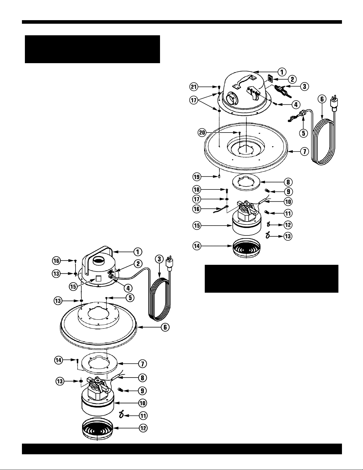
654M/655M/ (16")
1 HP Air-Thru Motor Head
EPLACEMENT PARTS LIST
R
________________________________
Ref Part Description Qty Part
No No
________________________________
1 Complete Head Assembly 1 341444
2 Push-In Cap Plug 1 312509
3 Switch Assembly 1 306940
4 #10-24 X
5 Strain Relief 1 318329
6 30 Ft, 18/3 Line Cord 1 318647
7 16" Cover Assembly 1 320617
8 Gasket 1 365394
9 Orange Wire Connector 1 398985
10 Insulation Tube 1 363685
11 Yellow Wire Connector 2 350648
12 Small Purse Lock 1 365491
13 Large Purse Lock 1 365483
14 Motor Guard 1 422398
15 1 HP Air-Thru Motor 1 350699
16 Ground Lead w/Terminals 1 307440
17 #12 Int Tooth Lockwasher 3 364037
18 #10-32 X .31 Ground Screw1 393258
19 Screw Protector 6 341649
20 #10-32 X
21 #12 X 1/
________________________________
3
/4" Screw 1 337315
5
/8" Screw 4 310913
" Screw 6 314595
2
OTOR HEAD
M
641M/652M/653M - 14"
1 HP Motor Head
________________________________
Ref Part Description Qty Part
No No
________________________________
Complete Head Assembly 1 341037
1 Dome Assembly 1 310832
2 Switch Assembly 1 306940
3 30 Ft, 18/3 Line Cord 1 318647
4 Strain Relief 1 318329
5 #10-32 X
6 14" Cover 1 310565
7 Circle Gasket 1 365394
8 Insulation Tube 1 363685
9 Orange Wire Connector 3 398985
10 1 HP, Air-Thru Motor 1 350699
11 Purse Lock 1 365483
12 Motor Guard 1 422398
13 #12 Int Tooth Lockwasher 3 364037
14 #10-32 X
15 Cap Plug 1 312509
16 #10 X
________________________________
5
/8" Screw 4 310913
5
/16" Screw 1 393258
1
/
2
" Screw 6 310824
PAGE 5
Page 6
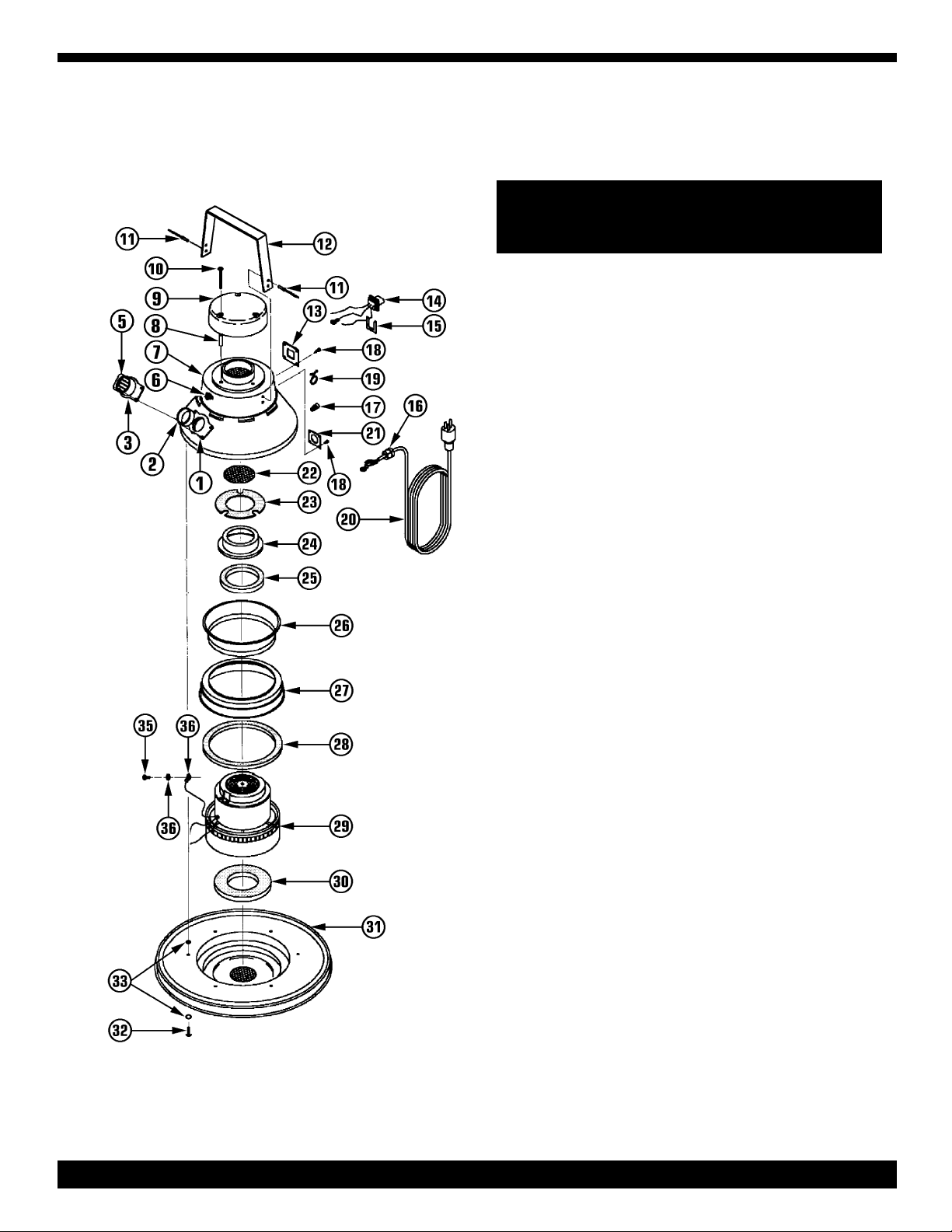
MOTOR HEAD
REPLACEMENT PARTS LIST
660M/661M (16" Dia)
16" - 21/4HP Motor Head
___________________________________
Ref Part Description Qty Part
No No
___________________________________
Complete Head Assembly 1 369896
1 Exhaust Connector Gasket 1 364606
2 Flat Gasket 1 368008
3 Air Deflector Exhaust 1 367958
5A Exhaust Assembly 1 346764
5B Exhaust Connector w/Pins 1 364665
6 Switch 1 324140
7A Dome Assembly 1 369551
7B Dome 1 367818
8 Steel Spacer 3 367842
9 Dome Cover 1 367850
10 #10-24 X 1
11 Handle Pop Rivets 4 318906
12 Carrying Handle 1 367834
13 Receptacle Mounting Plate 1 367990
14 Convenience Outlet 1 341746
15 Retainer Clips 1 341932
16 Strain Relief 1 318329
17 Yellow Wire Connector 4 350648
18 #6-32 X
19 Large Purse Lock 2 365483
20 30 Ft, 14/3 Line Cord 1 312789
21 Strain Relief Mounting Plate 1 367982
22 Disc Screen 1 367893
23 Pyrell Gasket 1 367885
24 Air Conductor Spinning 1 367974
25 Top Motor Gasket 1 317446
26 Motor Holdown Spinning 1 367915
27 Air Collector Assembly 1 367931
28 Flat Gasket 1 379158
29 2
30 Motor Gasket 1 378607
31 16" Cover Assembly 1 373206
32 #10-24 X
33 #12 Internal Tooth Lockwasher 2 364037
34 Electrical Terminal 1 319724
35 #10-24 X
36 #10-24 Hex Nut w/Lockwasher3 331201
___________________________________
1
/4HP By-Pass Motor 1 304301
3
/4" Screw 3 366676
1
/4" Screw 8 349402
1
/2" Screw 6 372633
3
4
" Screw 1 337315
/
PAGE 6
Page 7
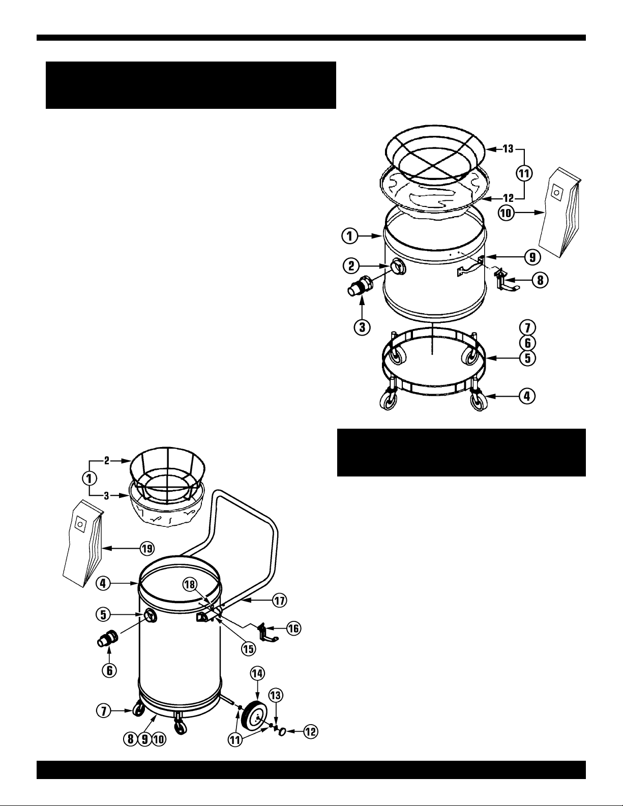
641M / 652M / 653M (14" Dia)
654M / 660M (16" Dia) Tanks w/Casters
________________________________________
Ref Part Description Qty Part
No No
________________________________________
1A 641M 14" Tank w/Hardware 1 341010
1B 652M 14" Tank w/Hardware 1 341045
1C 653M 14" Tank w/Hardware 1 341053
1C 654M/660M 16" Tank w/Hardware 1 341436
2 Inlet Fitting 1 325406
31
421/2" Swivel Casters (641M 3 Casters) 4 307408
5A 3-Socket 14" Wire Dolly (641M) 1 374881
5B 4-Socket 14" Wire Dolly
5C 4-Socket 16" Wire Dolly (654M / 660M) 1 374911
6 #12-14 X 1" Screw 1 335169
7 #10-12 Hex Nut 1 311243
8 Holdown Clamps 3 358312
9 Lift Handles
10A Disposable Filter Bags (641M-5/Pk) 1 356212
10B Disposable Filter Bags
10C Disposable Filter Bags (654M/660M-5/Pk)1 333115
11A 14" Pancake Filter Assembly 1 306428
11B 16"Deep Dish Filter Assembly 1 306444
12A 14" Cloth Filter w/Gasket 1 306452
12B 16" Cloth Filter w/Gasket 1 306479
13A 14" Filter Frame 1 304158
13B 16" Filter Frame 1 304107
1
/2" Hose Connector 1 349445
(652M / 653M) 1 374903
(Except 641M / 652M) 2 374261
(652M/653M-5/Pk)1 356891
________________________________________
VACUUM TANK
REPLACEMENT PARTS LIST
655M / 661M (16" Dia)
Tank w/Glidemobile
___________________________________
Ref Part Description Qty Part
No No
___________________________________
1 16" Deep Dish Filter Assembly 1 306444
2 16" Filter Frame 1 304107
3 16" Cloth Filter W/Gasket 1 306479
4 Tank Assembly 1 326232
5 Inlet Fitting 1 325406
1
61
721/2" Swivel Caster 4 307408
8 Glidemobile Dolly 1 319783
9
101/4- 20 X 11/2" Bolt 1 345555
11 Steel Washer 4 315435
12 Chrome Hub Cap 2 319317
13
14 8" Wheels 2 319309
15 Handle Brackets 2 376949
16 Holdown Clamps 3 358312
17 Push Handle 1 376906
18 Speed Pin Assembly 2 385182
19 Disposable Filter Bags
/2" Hose Connector 1 349445
1
/4- 20 Hex Nut 1 338966
1
/
2
" X 1" Palnut 2 319619
(5/Pk) 1 333115
___________________________________
PAGE 7
Page 8
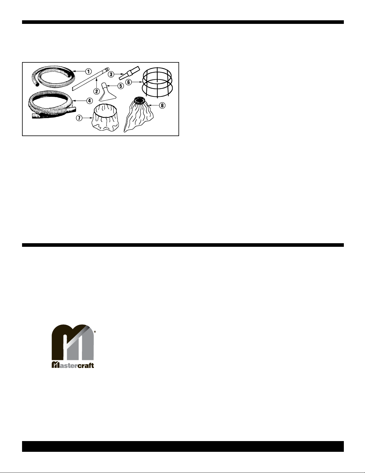
TOOLS, ACCESSORIES
AND OPTIONAL FILTERS
________________________________
Ref Description Part
No No
________________________________
1 6 Ft Flexible Metal Hose 304409
2 27" Crevice Tool 304352
3 Blower Nozzle 304425
4 10 Ft Rubber Lined Canvas Hose 344923
5 Upholstery Tool 386413
6 14" Hose Cage
7A 14"-2 Ply Intermediate Filter 347515
7B 16"-2 Ply Intermediate Filter 363375
8A 14" Dacron Filter Bag 300861
8B 16" Dacron Filter Bag 300888
________________________________
(For 14" Tanks) 313408
Optional Filters
Optional Filters
The use of the Intermediate or Dacron Bag Filter gives added protection to the motor head and life to the cloth filter.
Dacron Filter Bag
2 Ply Intermediate Filter
1) Install a disposable paper filter bag on
to the vacuum inlet fitting.
2) Install the Dacron Filter Bag in around
the outside of the cloth filter assembly so
the elastic top sits on the filter's gasket.
3) Position the filter assembly on top of
the tank, replace the motor head on tank
and close the clamps.
TROUBLE
SHOOTING
GUIDE
Address:
777 South Street, P. O. Box 2310
Newburgh NY 12500-0606
Tel:
(800) 835-7812 W (845) 565-8850
Fax:
(800) 752-6883 W (845) 565-9392
E-Mail
1) Install a disposable paper filter bag on
to the vacuum inlet fitting.
2) Place the 2 Ply Intermediate Filter in
position on top of tank,
3) Folding the filter over the outside of
tank. Overlap it approximately one inch.
4) Place the cloth filter assembly on the
the tank, being carefully not to move 2 ply
filter. The filter's gasket must sit evenly on
the tank rim so that an air tight seal will
be obtained.
5) Replace motor head assembly on top
of the filter assembly, and resnap
holdown clamps.
PROBLEM: Loss of Vacuum.
CAUSE: SOLUTION:
1) Full paper filter bag. 1) Replace paper filter bag.
2) Dry filter clogged or gasket worn 2) Clean cloth filter or replace gasket.
3) Clogged hose or wand. 3) Remove obstruction.
4) Canister rim dented. 4) Replace canister.
5) Loose or broken fan. 5) Contact manufacturer or service center.
6) Motor not working. 6) Contact manufacturer or service center.
PROBLEM: Motor is not running.
CAUSE: SOLUTION:
1) Faulty ON/OFF switch. 1) Contact manufacturer or service center.
2) Power cord defective. 2) Contact manufacturer or service center.
3) Loose connection or wiring. 3) Contact manufacturer or service center.
4) Motor defective. 4) Contact manufacturer or service center.
5) Blown fuse or tripped circuit breaker. 5) Replace fuse or reset circuit breaker.
PROBLEM: Dust blowing from vacuum when running.
CAUSE: SOLUTION:
1) Paper filter bag full or torn. 1) Replace filter bag.
2) Paper filter bag not installed 2) Reinstall or replace paper filter bag
properly.
properly or off inlet tube.
Sootmaster Manual - PN 376566 Rev G - Printed in USA 03/09/05
PAGE 8
 Loading...