

Page 1
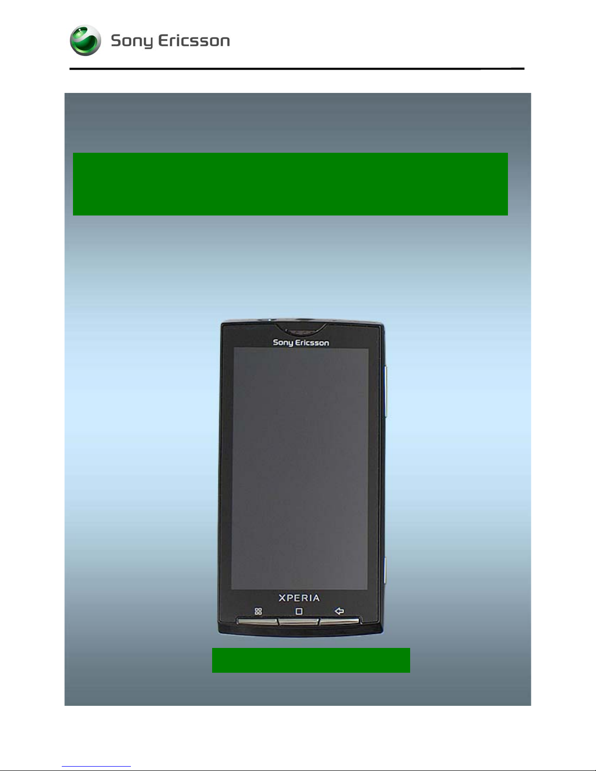
Working Instructions
- mechanical -
1230-2324 Rev 6
Sony Ericsson Mobile Communications AB – Company Internal
X10i, X10a, SO-01B
Page 2

Working Instruction Repair Instruction Mechanical/
CONTENTS
1 Exterior Views ................................................................................. 4
1.1 X10i, X10a ............................................................................................... 4
1.2 SO-01B ................................................................................................... 5
2 Tools ................................................................................................ 6
3 Disassembly.................................................................................... 7
3.1 Battery Cover ......................................................................................... 7
3.2 Battery .................................................................................................... 7
3.3 Rear Cover Assy .................................................................................... 8
3.4 Non-Celler Antenna Speaker Box ...................................................... 10
3.5 Main PBA .............................................................................................. 12
3.6 Frame Sub Assembly .......................................................................... 13
4 Replacement ................................................................................. 15
4.1 Battery Cover ....................................................................................... 15
4.2 Rear Cover Assy .................................................................................. 15
4.3 Front Cover Assy ................................................................................ 15
4.4 Key Camera .......................................................................................... 15
4.5 Key Volume .......................................................................................... 16
4.6 Adhesive Frame Sub Assembly ......................................................... 17
4.7 Audio Jack Connector ........................................................................ 19
4.8 Audio Jack Holder ............................................................................... 20
4.9 Camera 8 MPixel CMOS ...................................................................... 21
4.10 Co-Brand .............................................................................................. 23
4.11 Conductive Gasket .............................................................................. 25
4.12 Core Unit Label .................................................................................... 26
4.13 Cover Micro USB ................................................................................. 28
4.14 Cover Sensor ....................................................................................... 30
4.15 Cushion for Frame Key ....................................................................... 31
4.16 Display 4.0 TFT .................................................................................... 32
4.17 Frame Sub Assembly .......................................................................... 35
4.18 Key Main ............................................................................................... 39
4.19 Key On/Off ............................................................................................ 41
4.20 Main Antenna ....................................................................................... 43
4.21 Main Key FPC ...................................................................................... 45
4.22 Main Key Frame ................................................................................... 47
4.23 Non-Celler Antenna Speaker Box ...................................................... 49
4.24 Receiver FPC ....................................................................................... 51
4.25 Shield Can MComp Sheet Lid A1 ....................................................... 53
4.26 Shield Can MComp Sheet Lid A3 ....................................................... 54
1230-2324 Rev 6
Sony Ericsson Mobile Communications AB – Company Internal
2(81)
Page 3

Working Instruction Repair Instruction Mechanical/
4.27 Shield Can MComp Sheet Lid A4 ....................................................... 55
4.28 Shield Can MComp Sheet Lid A5 ....................................................... 57
4.29 Shield Can Lid A1 ................................................................................ 59
4.30 Shield Can Lid A2 ................................................................................ 61
4.31 Shield Can Lid A3 ................................................................................ 62
4.32 Shield Can Lid A4 ................................................................................ 64
4.33 Shield Can Lid A5 ................................................................................ 66
4.34 Shield Can Lid B1 ................................................................................ 68
4.35 Shield Can Lid B2 ................................................................................ 69
4.36 SIM and MicroSD FPC ......................................................................... 70
4.37 Board Swap—Replace Swap Board .................................................. 72
4.38 Board Swap – Change Label .............................................................. 72
4.39 Board Swap – Customize Software ................................................... 72
5 Reassembly................................................................................... 73
5.1 Front Cover Assy & Frame Sub Assembly ....................................... 73
5.2 Main PBA .............................................................................................. 74
5.3 Non-Celler Antenna Speaker Box ...................................................... 75
5.4 Rear Cover Assy .................................................................................. 77
5.5 Battery .................................................................................................. 79
5.6 Battery Cover ....................................................................................... 79
6 Country of origin Barcodes for Brazil/VIVO Labels .................. 80
7 Revision History ........................................................................... 81
For general information about mechanical repair related issues, refer to
1220-1333: Generic Repair Manual - mechanical
1230-2324 Rev 6
Sony Ericsson Mobile Communications AB – Company Internal
3(81)
Page 4
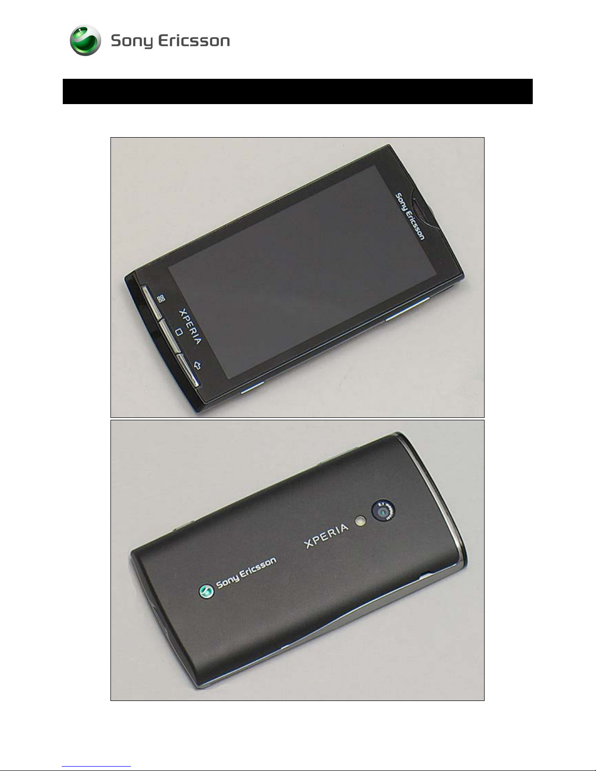
1 Exterior Views
1.1 X10i, X10a
Working Instruction Repair Instruction Mechanical/
1230-2324 Rev 6
Sony Ericsson Mobile Communications AB – Company Internal
4(81)
Page 5
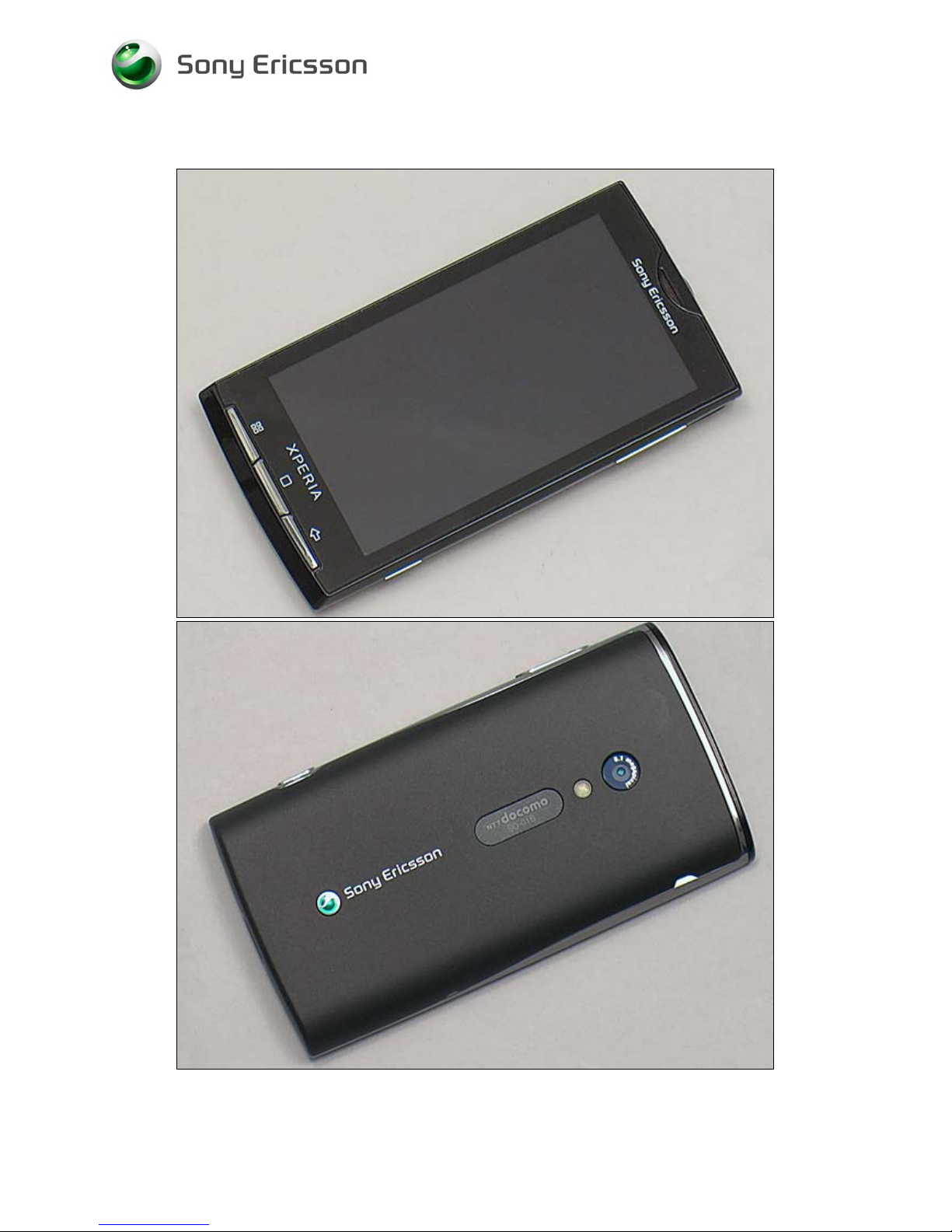
1.2 SO-01B
Working Instruction Repair Instruction Mechanical/
1230-2324 Rev 6
Sony Ericsson Mobile Communications AB – Company Internal
5(81)
Page 6
Working Instruction Repair Instruction Mechanical/
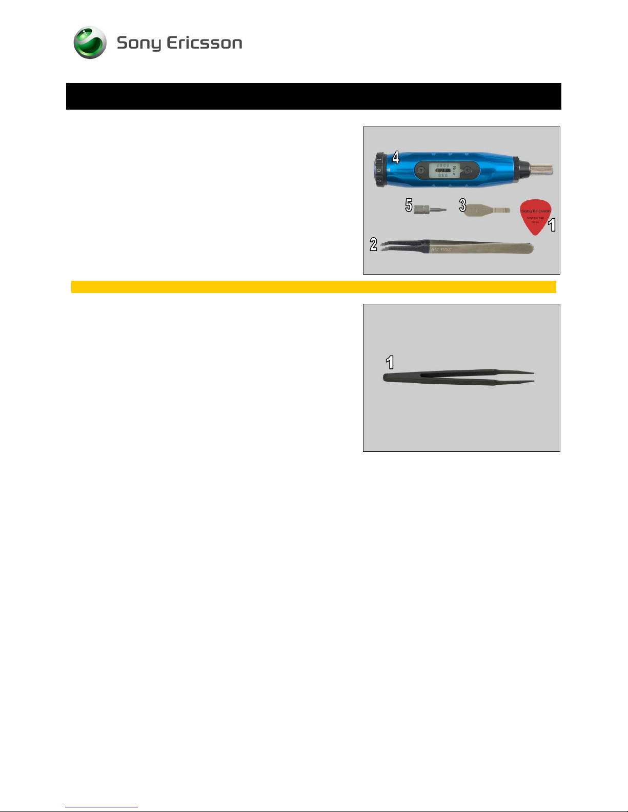
2 Tools
SPECIAL TOOLS
1. Guitar Pick
2. Flex Film Assembly Tool
3. Front Opening Tool
4. Torque Screwdriver
5. Bits(T6)
For part no’s on the tools above, refer to the ‘Tools Catalogue/Matrix’!
STANDARD TOOLS
1. Tweezers
1230-2324 Rev 6
Sony Ericsson Mobile Communications AB – Company Internal
6(81)
Page 7
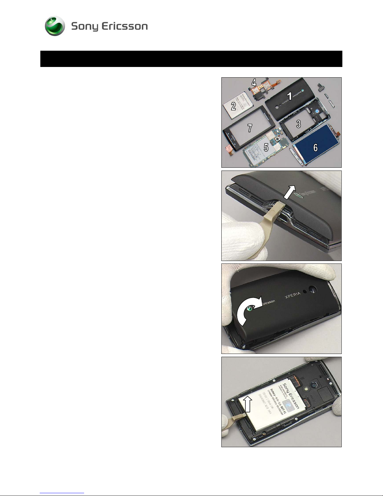
3 Disassembly
The disassembly is done in the following order:
1. Battery Cover
2. Battery
3. Rear Cover Assy
4. Non-Celler Antenna Speaker Box
5. Main PBA
6. Frame Sub Assembly
7. Front Cover Assy
Working Instruction Repair Instruction Mechanical/
3.1 Battery Cover
Insert Front Opening Tool to release the hook of the Battery
Cover on the bottom side.
Lift to release the Battery Cover from the bottom side gently.
3.2 Battery
Lift up the Battery from its cavity by using a Front Opening
Tool.
1230-2324 Rev 6
Sony Ericsson Mobile Communications AB – Company Internal
7(81)
Page 8
Disassembly
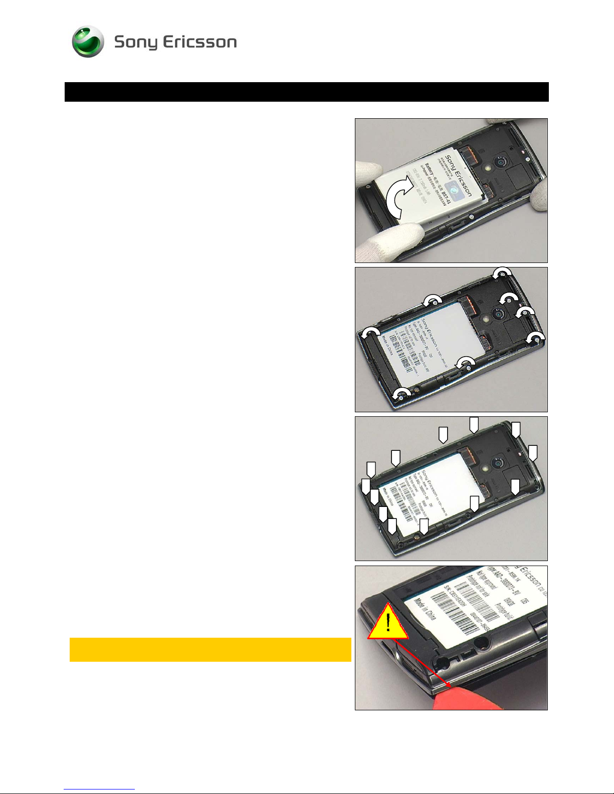
Remove the Battery.
Working Instruction Repair Instruction Mechanical/
3.3 Rear Cover Assy
Remove the eight screws by a screwdriver with T6
There are thirteen securing hooks as shown by the arrows.
Insert the Guitar Pick into the right side of the Rear Cover
Assy as shown.
Keep the Guitar Pick downward direction as shown to
make sure not to touch the edge of Rear Cover Assy
1230-2324 Rev 6
Sony Ericsson Mobile Communications AB – Company Internal
8(81)
Page 9
Working Instruction Repair Instruction Mechanical/
Disassembly
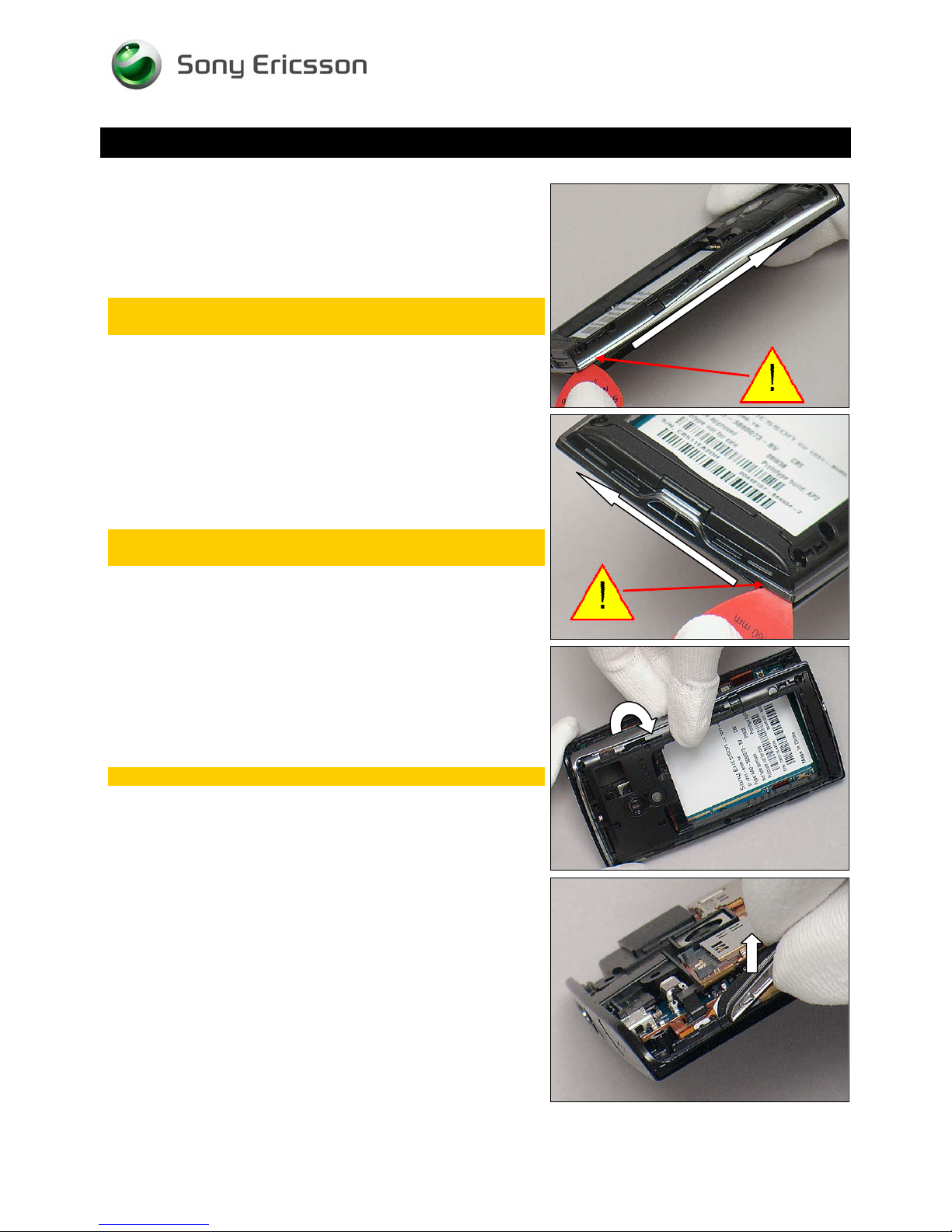
Push the Guitar Pick along gently to release the hooks of
this side.
Keep the Guitar Pick downward direction as shown to
make sure not to touch the edge of Rear Cover Assy
Push the Guitar Pick along gently to release the hooks of
bottom side.
Keep the Guitar Pick downward direction as shown to
make sure not to touch the edge of Rear Cover Assy!
Turn the Rear Cover Assy over from the right side to remove
it gently.
Be careful not to damage it! If damaged, scrap it.
Lift to remove the Key Volume.
1230-2324 Rev 6
Sony Ericsson Mobile Communications AB – Company Internal
9(81)
Page 10
Disassembly
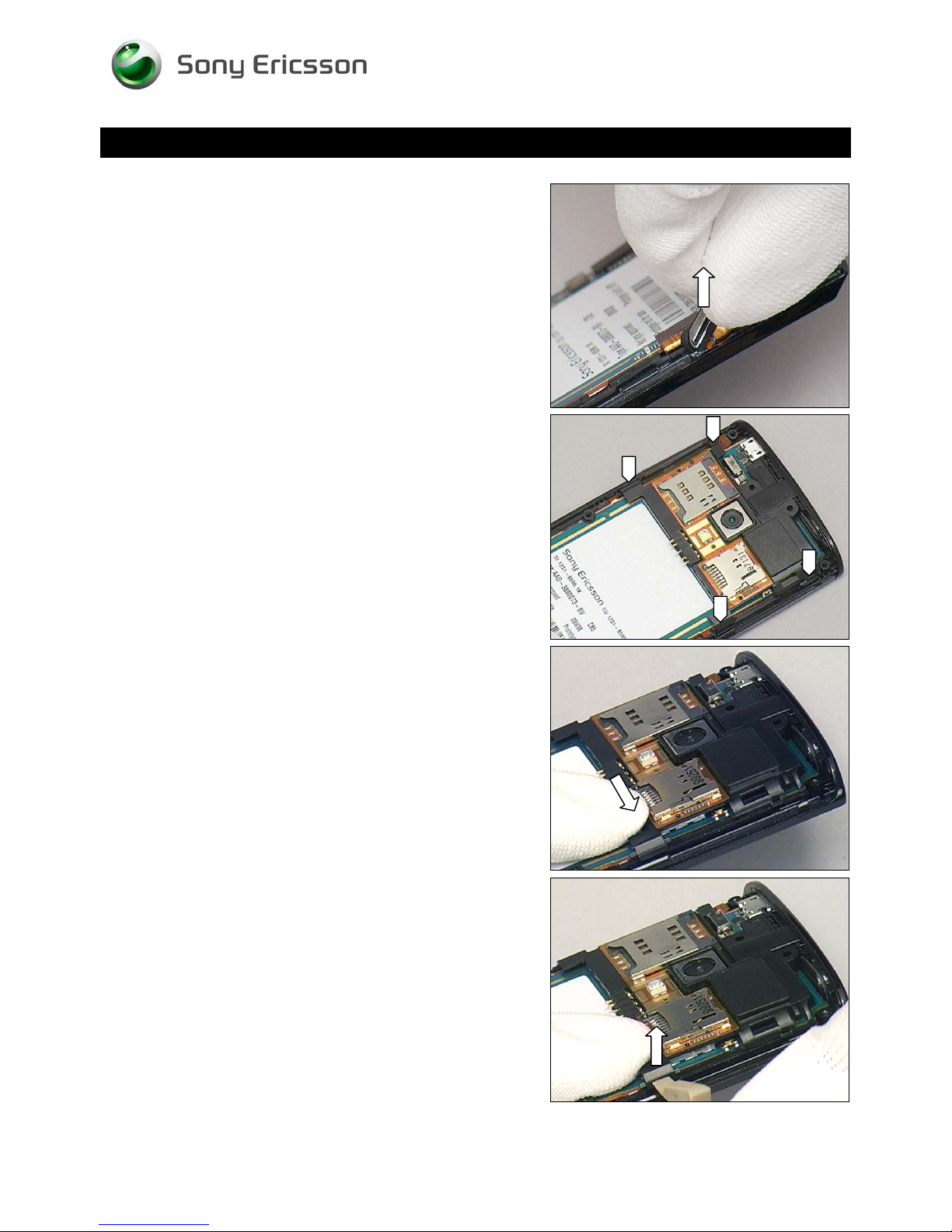
Lift to remove the Key Camera.
3.4 Non-Celler Antenna
Working Instruction Repair Instruction Mechanical/
Speaker Box
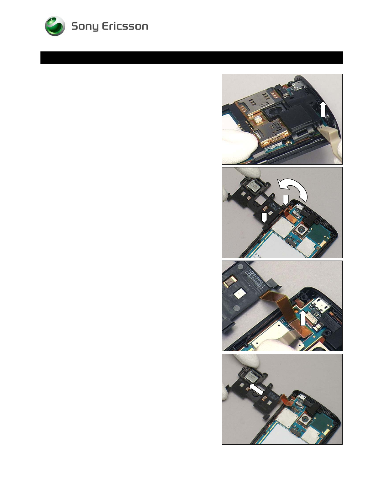
There are four securing hooks on the Non-Celler Antenna
Speak Box as shown by arrows.
Push the lower right hook of the Non-Celler Antenna Speak
Box by fingers as the arrows shown.
Unsnap the hook by using a Front Opening Tool.
1230-2324 Rev 6
Sony Ericsson Mobile Communications AB – Company Internal
10(81)
Page 11
Disassembly
Unsnap another hook on this side as shown.
Working Instruction Repair Instruction Mechanical/
Turn the Non-Celler Antenna Speak Box over to release the
other two hooks gently.
Disconnect the BtB connector by using a Front Opening
Tool.
Remove the Non-Celler Antenna Speak Box.
1230-2324 Rev 6
Sony Ericsson Mobile Communications AB – Company Internal
11(81)
Page 12
Working Instruction Repair Instruction Mechanical/
Disassembly
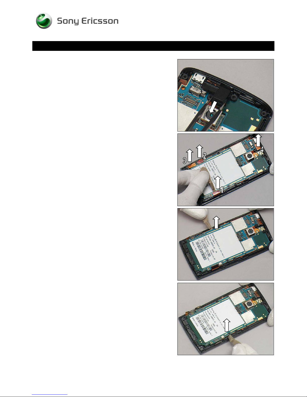
Remove the Audio Jack Holder by using a pair of tweezers.
3.5 Main PBA
Disconnect the four BtB connectors of the Unit by using a
Front Opening Tool.
Insert the Front Opening Tool to release the Main PBA from
the left side.
Do the same on the opposite side.
1230-2324 Rev 6
Sony Ericsson Mobile Communications AB – Company Internal
12(81)
Page 13
Disassembly
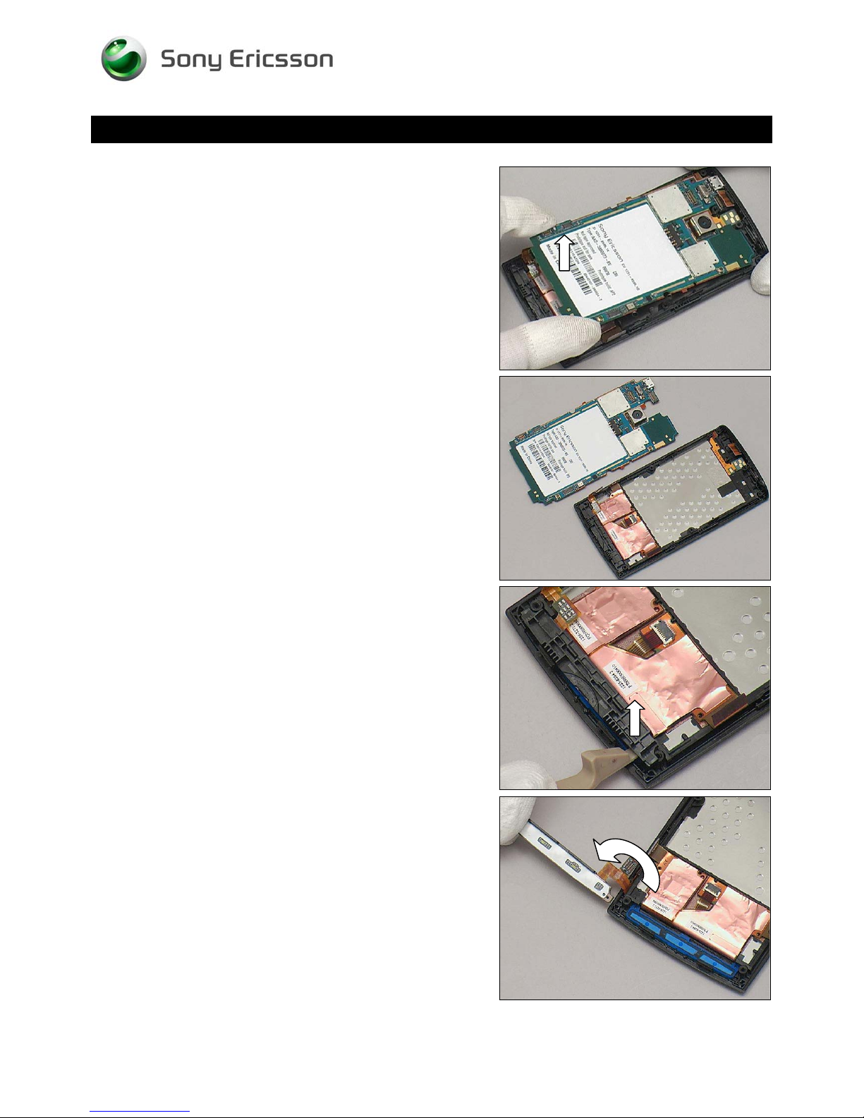
Lift up the bottom of the Main PBA gently.
Working Instruction Repair Instruction Mechanical/
Separate the Main PBA and the Unit carefully.
3.6 Frame Sub Assembly
Insert the Front Opening Tool underneath the Main Key Unit
to release it.
Turn over the Main Key Unit as the arrow shown.
1230-2324 Rev 6
Sony Ericsson Mobile Communications AB – Company Internal
13(81)
Page 14
Working Instruction Repair Instruction Mechanical/
Disassembly
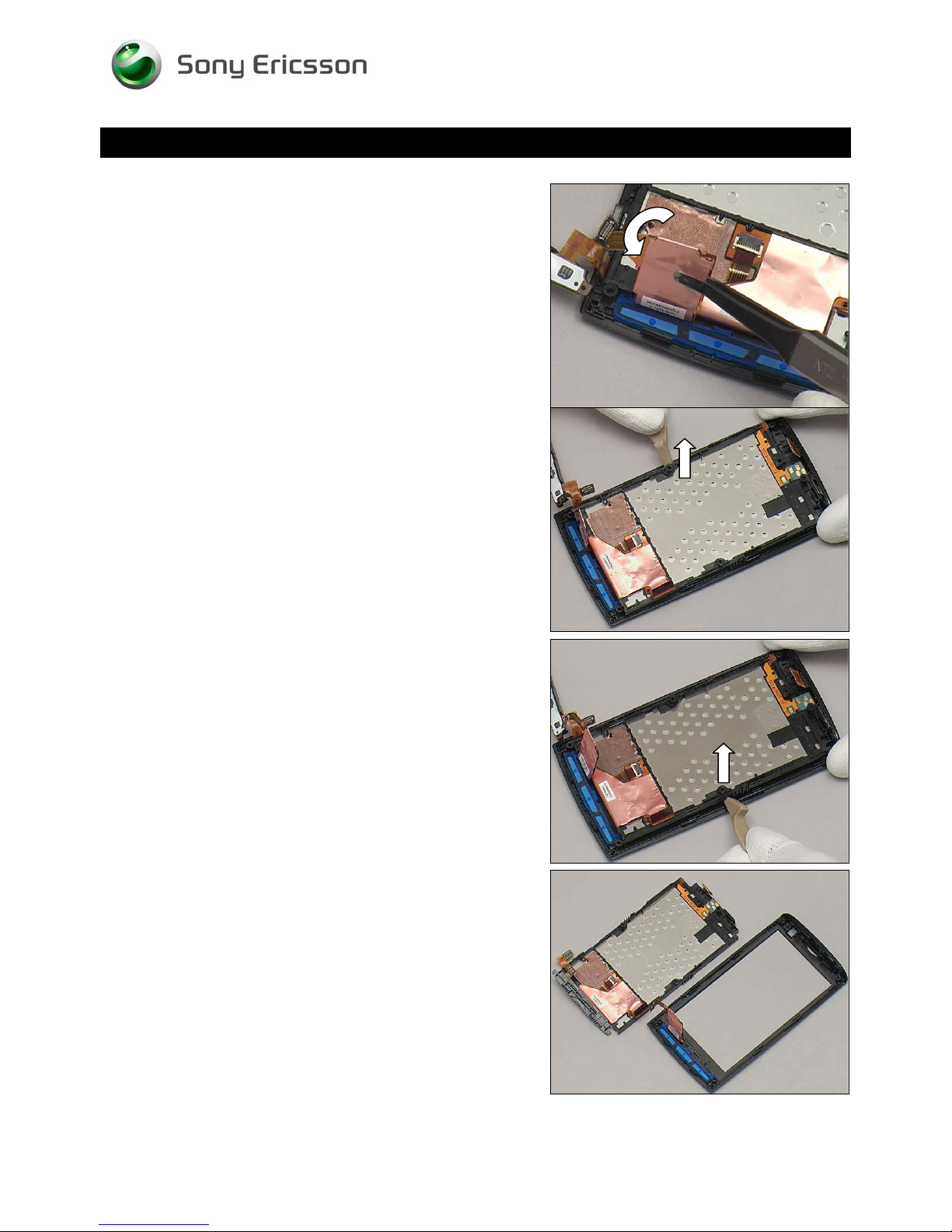
Detach the FPC from the adhesive slightly by using a Flex
Film Assembly Tool.
Release the Frame Sub Assembly with a Front Opening
Tool on the left side.
Do the same on the opposite side.
Separate the Frame Sub Assembly and the Front Cover
Assy.
1230-2324 Rev 6
Sony Ericsson Mobile Communications AB – Company Internal
14(81)
Page 15
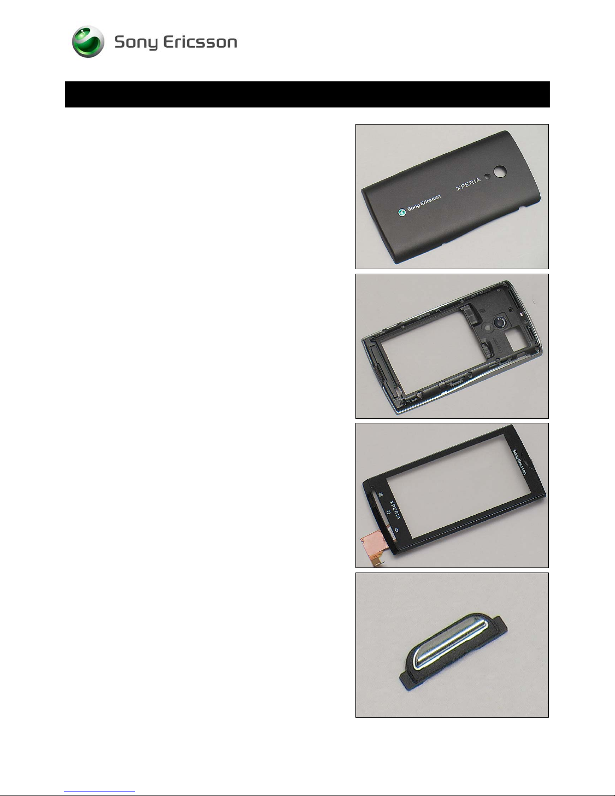
4 Replacement
4.1 Battery Cover
Follow the 3.1 Disassembly instructions!
Prepare a new Battery Cover.
Follow the 5.6 Reassembly instructions!
Working Instruction Repair Instruction Mechanical/
4.2 Rear Cover Assy
Follow the 3.1 – 3.3 Disassembly instructions!
Prepare a new Rear Cover Assy
Follow the 5.4 – 5.6 Reassembly instructions!
4.3 Front Cover Assy
Follow the 3.1 – 3.6 Disassembly instructions!
Prepare a new Front Cover Assy.
Follow the 5.1 – 5.6 Reassembly instructions!
4.4 Key Camera
Follow the 3.1 – 3.3 Disassembly instructions!
Prepare a new Key Camera.
Follow the 5.4 – 5.6 Reassembly instructions!
1230-2324 Rev 6
Sony Ericsson Mobile Communications AB – Company Internal
15(81)
Page 16
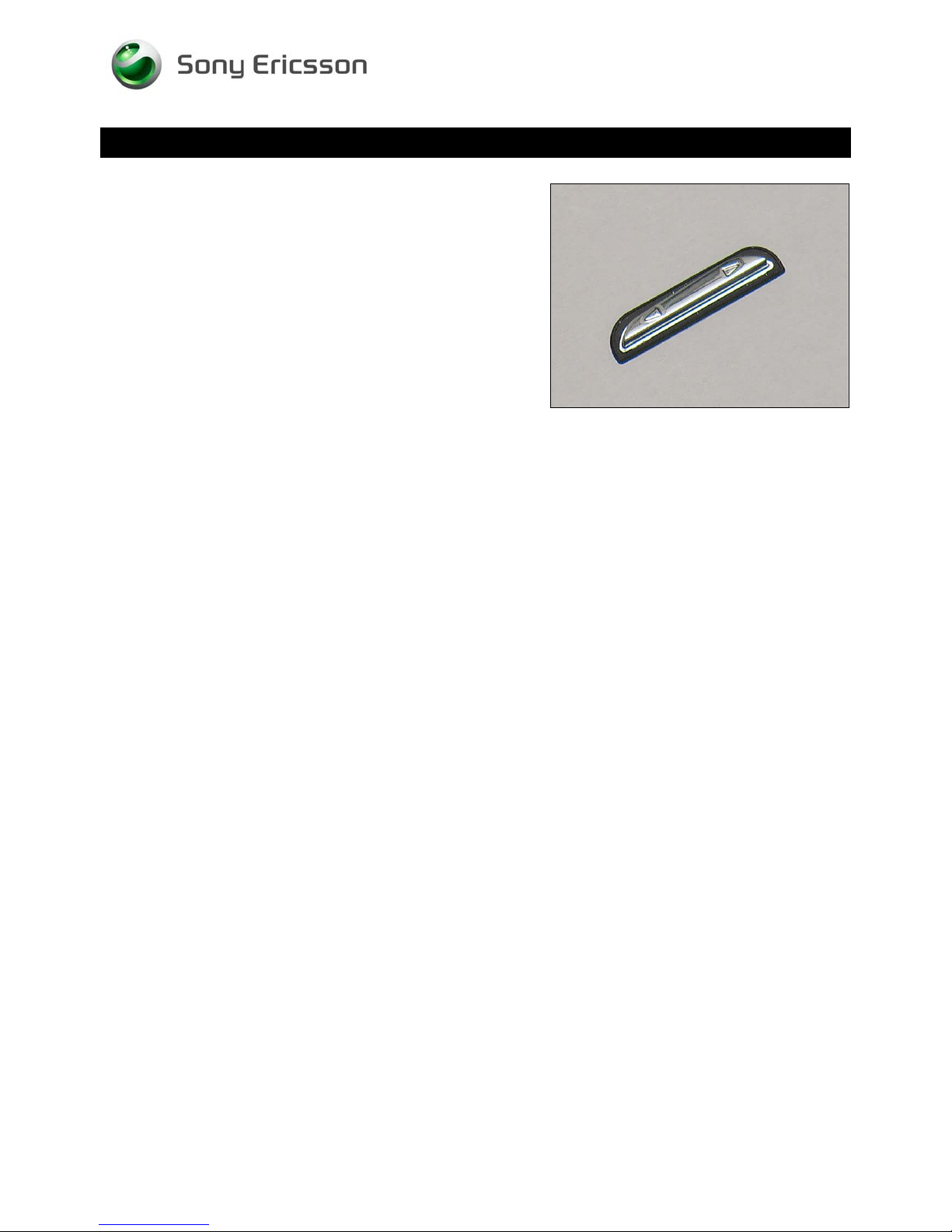
Replacement
4.5 Key Volume
Follow the 3.1 – 3.3 Disassembly instructions!
Prepare a new Key Volume.
Follow the 5.4 – 5.6 Reassembly instructions!
Working Instruction Repair Instruction Mechanical/
1230-2324 Rev 6
Sony Ericsson Mobile Communications AB – Company Internal
16(81)
Page 17
Working Instruction Repair Instruction Mechanical/
Replacement
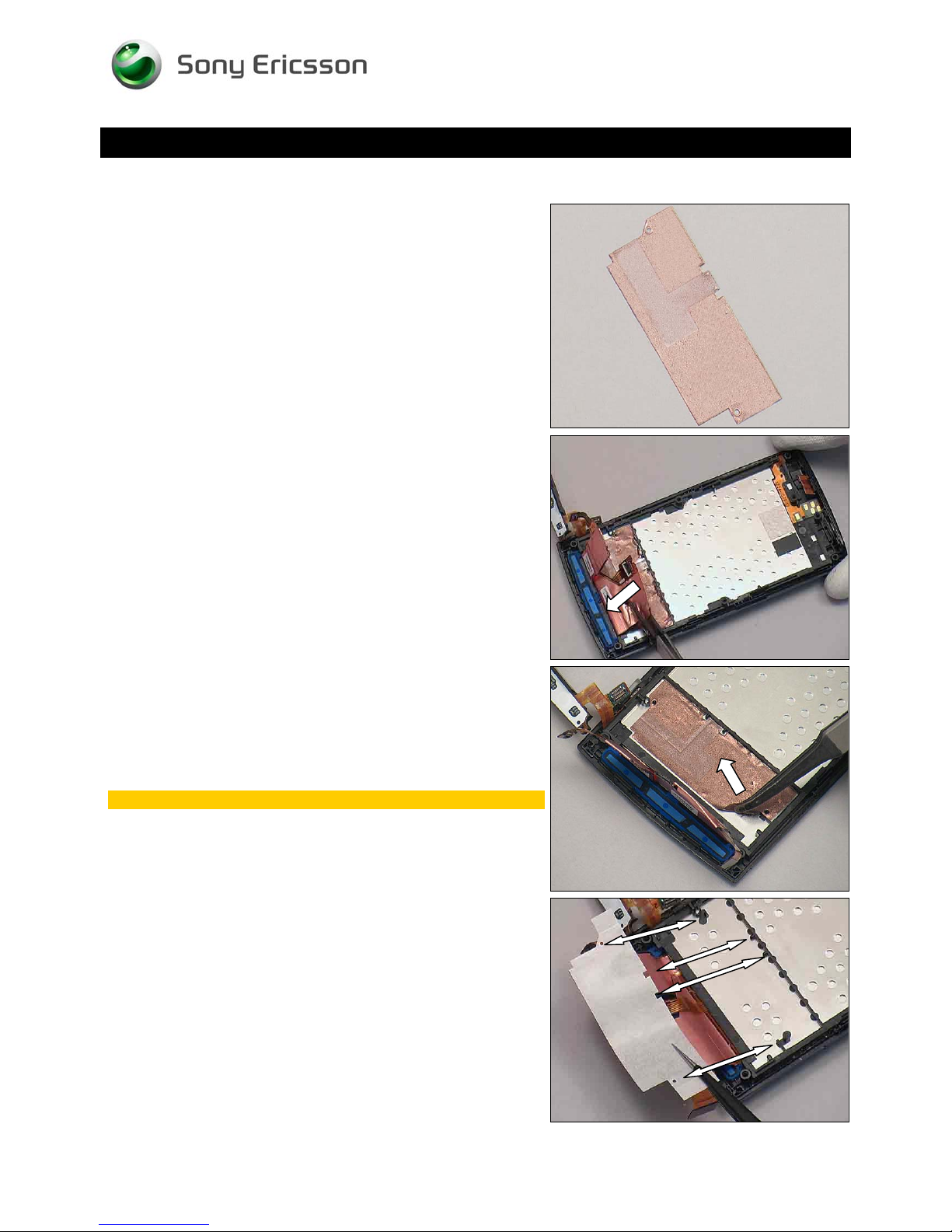
4.6 Adhesive Frame Sub Assembly
Follow the 3.1 – 3.5 Disassembly instructions!
Prepare a new Adhesive Frame Sub Assembly.
Follow the 5.2 – 5.6 Reassembly instructions!
REMOVAL
Detach the FPC from the Adhesive Frame Sub Assembly by
using a Flex Film Assembly Tool.
Peel off the Adhesive Frame Sub Assembly by using a Flex
Film Assembly Tool.
Scrap! Cannot be reused!
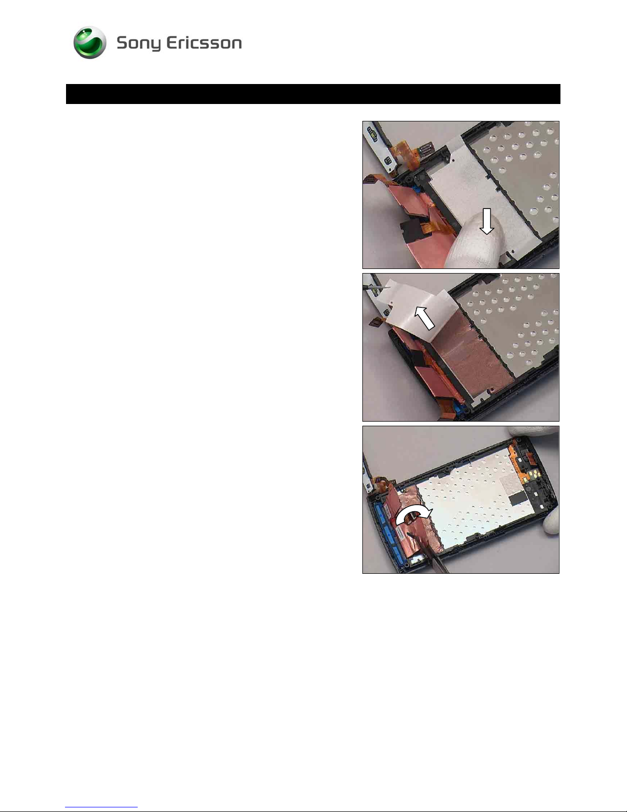
INSTALLATION
Put a new Adhesive Frame Sub Assembly align guiding
poles.
1230-2324 Rev 6
Sony Ericsson Mobile Communications AB – Company Internal
17(81)
Page 18
Working Instruction Repair Instruction Mechanical/
Replacement: Adhesive Frame Sub Assembly
Press to secure its attachment.
Peel off the protect film.
Turn over the FPC aligning guiding poles and press to
secure its attachment.
1230-2324 Rev 6
Sony Ericsson Mobile Communications AB – Company Internal
18(81)
Page 19
Replacement
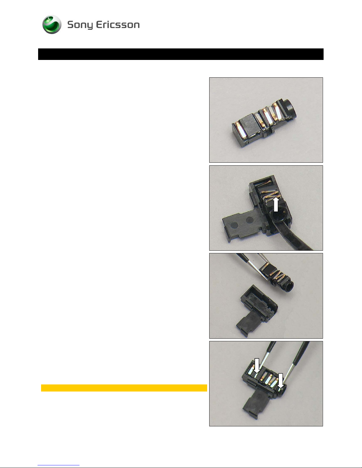
4.7 Audio Jack Connector
Follow the 3.1 – 3.4 Disassembly instructions!
Prepare a new Audio Jack Connector.
Follow the 5.3 – 5.6 Reassembly instructions!
Working Instruction Repair Instruction Mechanical/
REMOVAL
Detach to remove the Jack Connector from the head by
using a Flex Film Assembly Tool.
INSTALLATION
Place a new Jack Connector in place by using a pair of
tweezers.
Press to secure its attachment by using a pair of tweezers.
Do not touch the spring pins.
1230-2324 Rev 6
Sony Ericsson Mobile Communications AB – Company Internal
19(81)
Page 20
Replacement
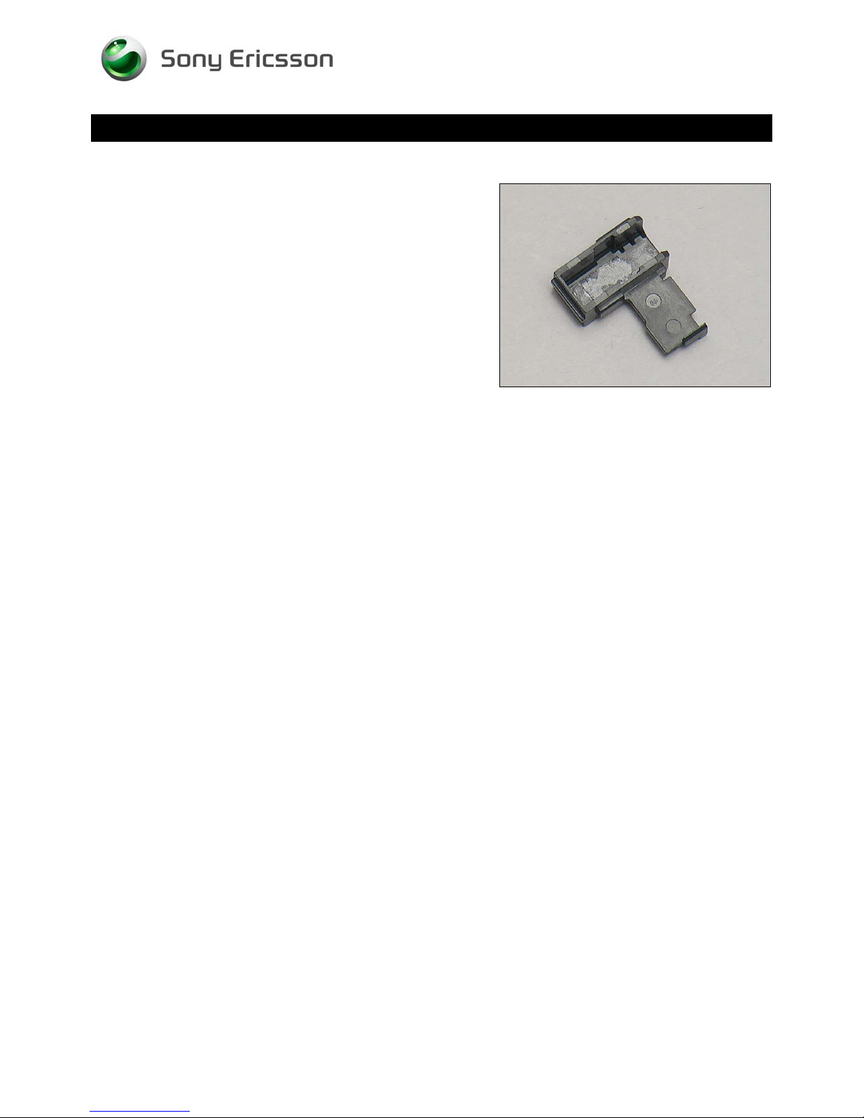
4.8 Audio Jack Holder
Follow the 3.1 – 3.4 Disassembly instructions!
Follow the 4.7 Removal instructions!
Prepare a new Audio Jack Holder.
Follow the 4.7 Installation instructions!
Follow the 5.3 – 5.6 Reassembly instructions!
Working Instruction Repair Instruction Mechanical/
1230-2324 Rev 6
Sony Ericsson Mobile Communications AB – Company Internal
20(81)
Page 21
Working Instruction Repair Instruction Mechanical/
Replacement
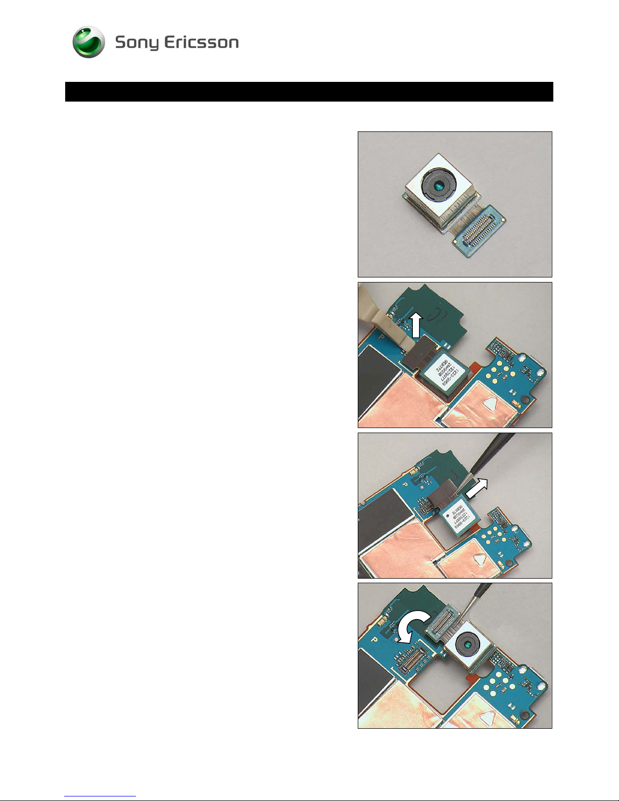
4.9 Camera 8 MPixel CMOS
Follow the 3.1 – 3.5 Disassembly instructions!
Prepare a new Camera 8 MPixel CMOS.
Follow the 5.2 – 5.6 Reassembly instructions!
REMOVAL
Unsnap the BtB connector by using a Front Opening Tool.
Remove the Camera 8 MPixel CMOS.
INSTALLATION
Place a new Camera 8 MPixel CMOS in place.
1230-2324 Rev 6
Sony Ericsson Mobile Communications AB – Company Internal
21(81)
Page 22
Working Instruction Repair Instruction Mechanical/
Replacement: Camera 8 MPixel CMOS
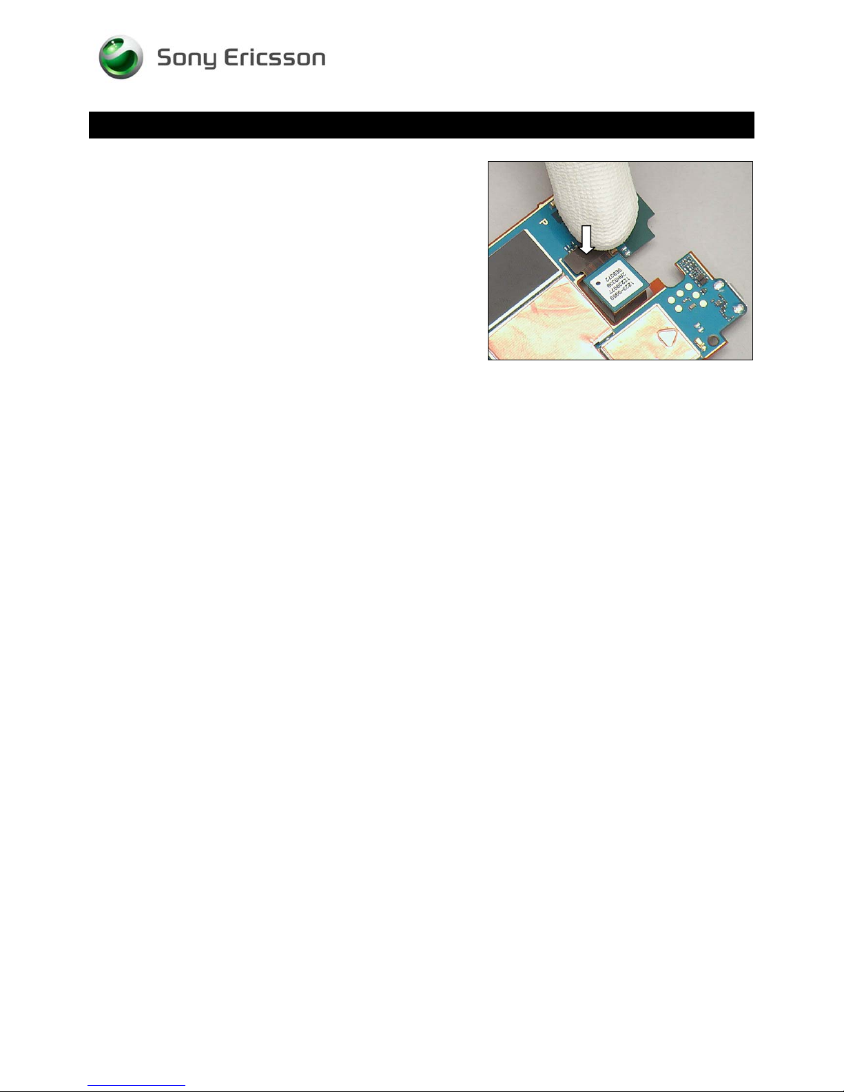
Press to snap it.
1230-2324 Rev 6
Sony Ericsson Mobile Communications AB – Company Internal
22(81)
Page 23
Replacement
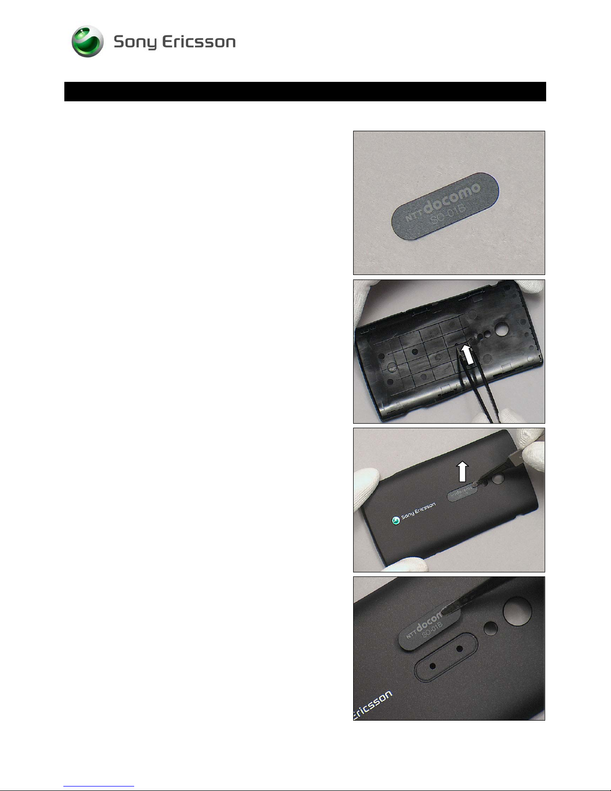
4.10 Co-Brand
Follow the 3.1 Disassembly instructions!
Prepare a new Co-Brand
Follow the 5.6 Reassembly instructions!
Working Instruction Repair Instruction Mechanical/
REMOVAL
Push from the hole on the back side of the Battery Cover
Co-brand Pocket by using a pair of tweezers.
Detach to remove the Co-Brand from the Battery Cover Cobrand Pocket.
INSTALLATION
Put a new Co-Brand in place.
1230-2324 Rev 6
Sony Ericsson Mobile Communications AB – Company Internal
23(81)
Page 24
Replacement: Co-Brand
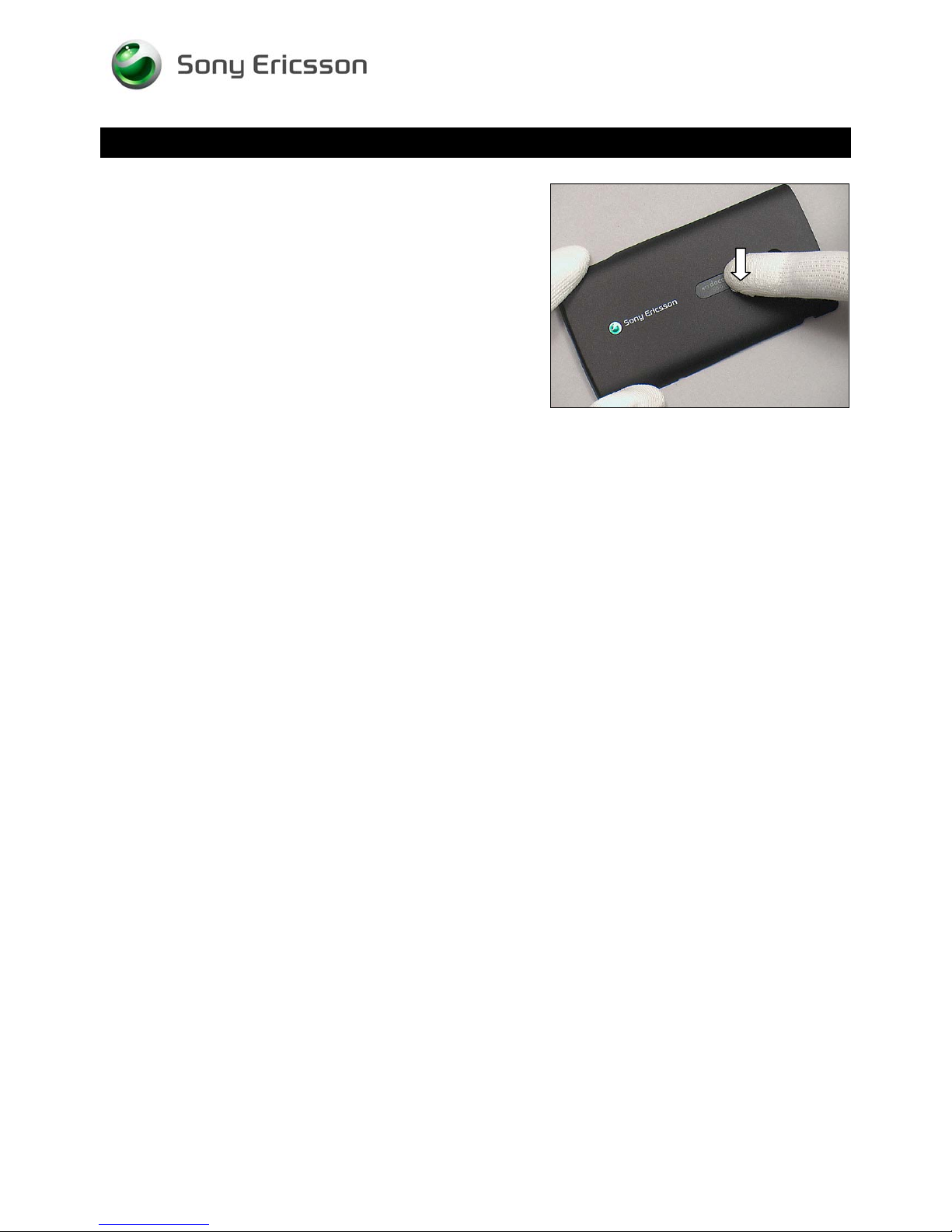
Press along to secure its attachment.
Working Instruction Repair Instruction Mechanical/
1230-2324 Rev 6
Sony Ericsson Mobile Communications AB – Company Internal
24(81)
Page 25
Replacement
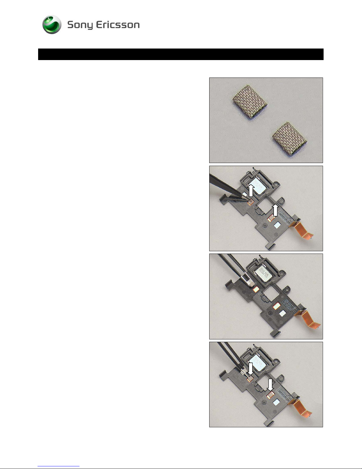
4.11 Conductive Gasket
Follow the 3.1 – 3.4 Disassembly instructions!
Prepare the new Conductive Gaskets
Follow the 5.3 – 5.6 Reassembly instructions!
Working Instruction Repair Instruction Mechanical/
REMOVAL
Detach the two Conductive Gaskets by using a pair of
tweezers.
INSTALLATION
Put two new Conductive Gaskets in place.
Press to secure the attachments.
1230-2324 Rev 6
Sony Ericsson Mobile Communications AB – Company Internal
25(81)
Page 26
Replacement
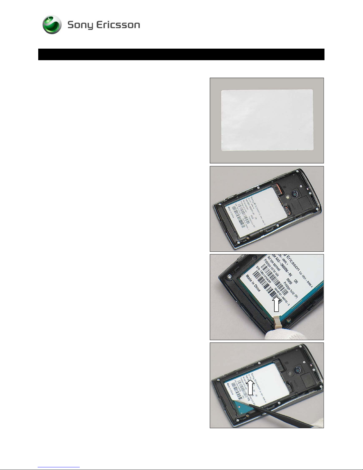
4.12 Core Unit Label
Follow the 3.1 – 3.2 Disassembly instructions!
Prepare a new Core Unit Label
Follow the 5.5 – 5.6 Reassembly instructions!
Working Instruction Repair Instruction Mechanical/
REMOVAL
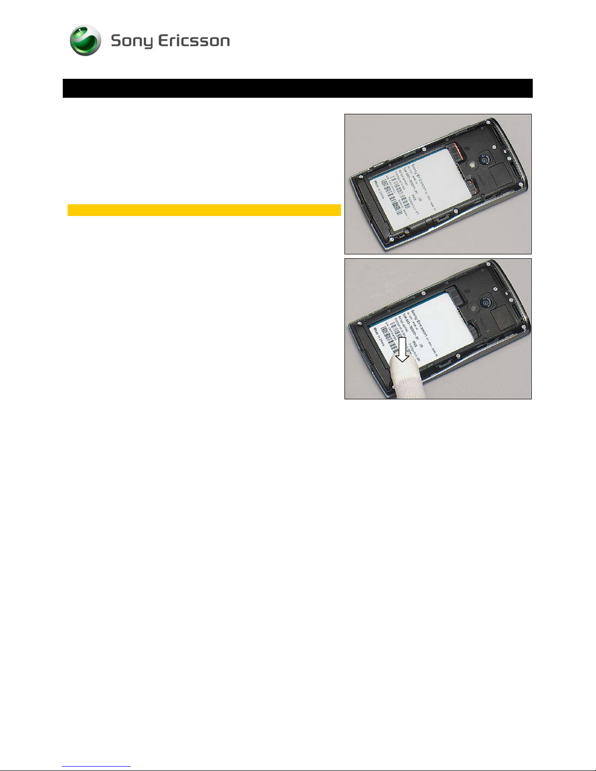
Read the old Core Unit Label and write the information into
the ‘LabelMake’ program.
Detach the Label from the corner by using a Front Opening
Tool.
Remove the Label carefully by using a pair of tweezers
1230-2324 Rev 6
Sony Ericsson Mobile Communications AB – Company Internal
26(81)
Page 27
Working Instruction Repair Instruction Mechanical/
Replacement: Core Unit Label
INSTALLATION
Check that the label format is properly loaded in the Zebra
printer and write a new Label by using the ‘Label Make’
software.
One label only is allowed!
Press the new Core Unit Label onto the Main PBA.
1230-2324 Rev 6
Sony Ericsson Mobile Communications AB – Company Internal
27(81)
Page 28
Replacement
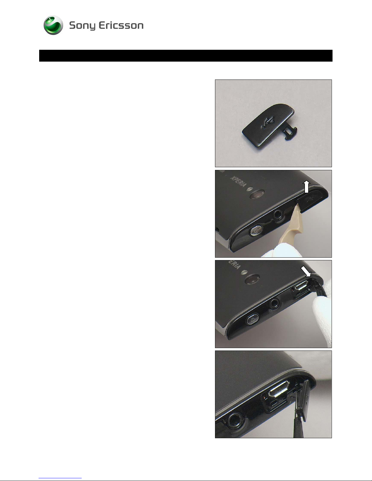
4.13 Cover Micro USB
Prepare a new Cover Micro USB.
Working Instruction Repair Instruction Mechanical/
REMOVAL
Unsnap the three hooks of the Cover Micro USB with a
Front Opening Tool.
Pull the Cover Micro USB out of the Phone gently.
INSTALLATION
Place a new Cover Micro USB with the proper direction.
1230-2324 Rev 6
Sony Ericsson Mobile Communications AB – Company Internal
28(81)
Page 29
Working Instruction Repair Instruction Mechanical/
Replacement: Cover Micro USB
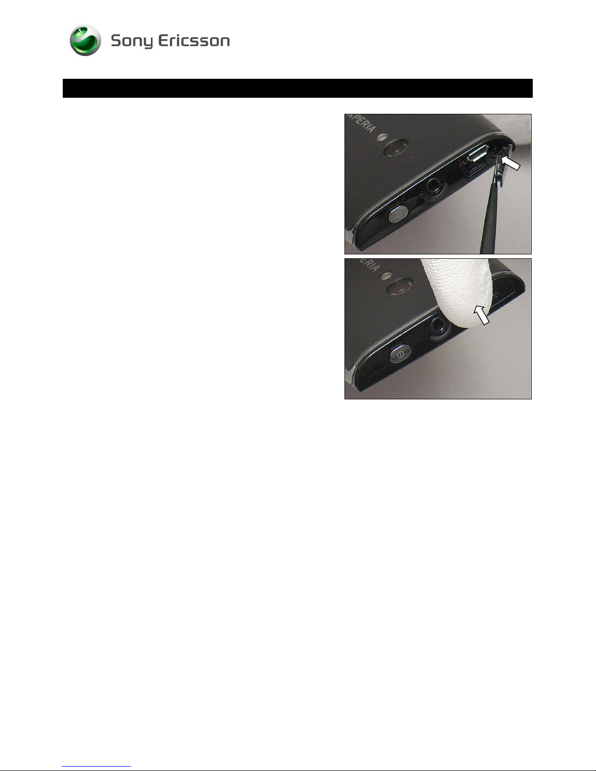
Push the Cover Micro USB Into the Phone into the cavity by
using a pair of tweezers
Press to snap the Cover Micro USB.
1230-2324 Rev 6
Sony Ericsson Mobile Communications AB – Company Internal
29(81)
Page 30
Replacement
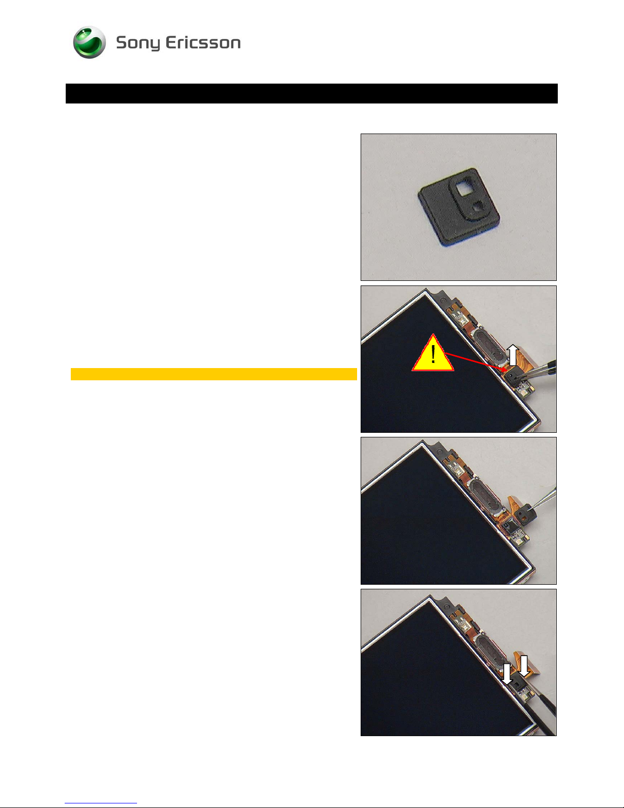
4.14 Cover Sensor
Follow the 3.1 – 3.6 Disassembly instructions!
Prepare a new Cover Sensor.
Follow the 5.1 – 5.6 Reassembly instructions!
Working Instruction Repair Instruction Mechanical/
REMOVAL
Remove it by using a pair of tweezers.
Do not damage the sensor.
INSTALLATION
Place a new Cover Sensor in place.
Press to secure its position.
1230-2324 Rev 6
Sony Ericsson Mobile Communications AB – Company Internal
30(81)
Page 31
Working Instruction Repair Instruction Mechanical/
Replacement
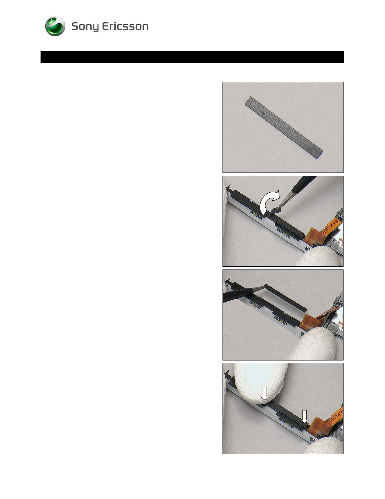
4.15 Cushion for Frame Key
Follow the 3.1 – 3.5 Disassembly instructions!
Prepare a new Cushion for Frame Key
Follow the 5.2 – 5.6 Reassembly instructions!
REMOVAL
Detach it by using a pair of tweezers.
INSTALLATION
Place a new Cushion for Frame Key in place.
Press to secure its position.
1230-2324 Rev 6
Sony Ericsson Mobile Communications AB – Company Internal
31(81)
Page 32
Replacement
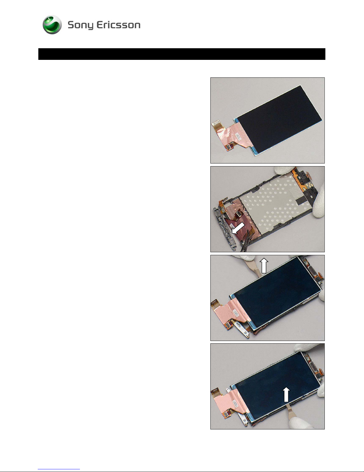
4.16 Display 4.0 TFT
Follow the 3.1 – 3.6 Disassembly instructions!
Prepare a new Display 4.0 TFT.
Follow the 5.1 – 5.6 Reassembly instructions!
Working Instruction Repair Instruction Mechanical/
REMOVAL
Detach the FPC from the Adhesive Frame Sub Assembly.
Turn over the Unit and release the Display 4.0 TFT with a
Front Opening Tool on the left side.
Do the same on the right side.
1230-2324 Rev 6
Sony Ericsson Mobile Communications AB – Company Internal
32(81)
Page 33
Replacement: Display 4.0 TFT
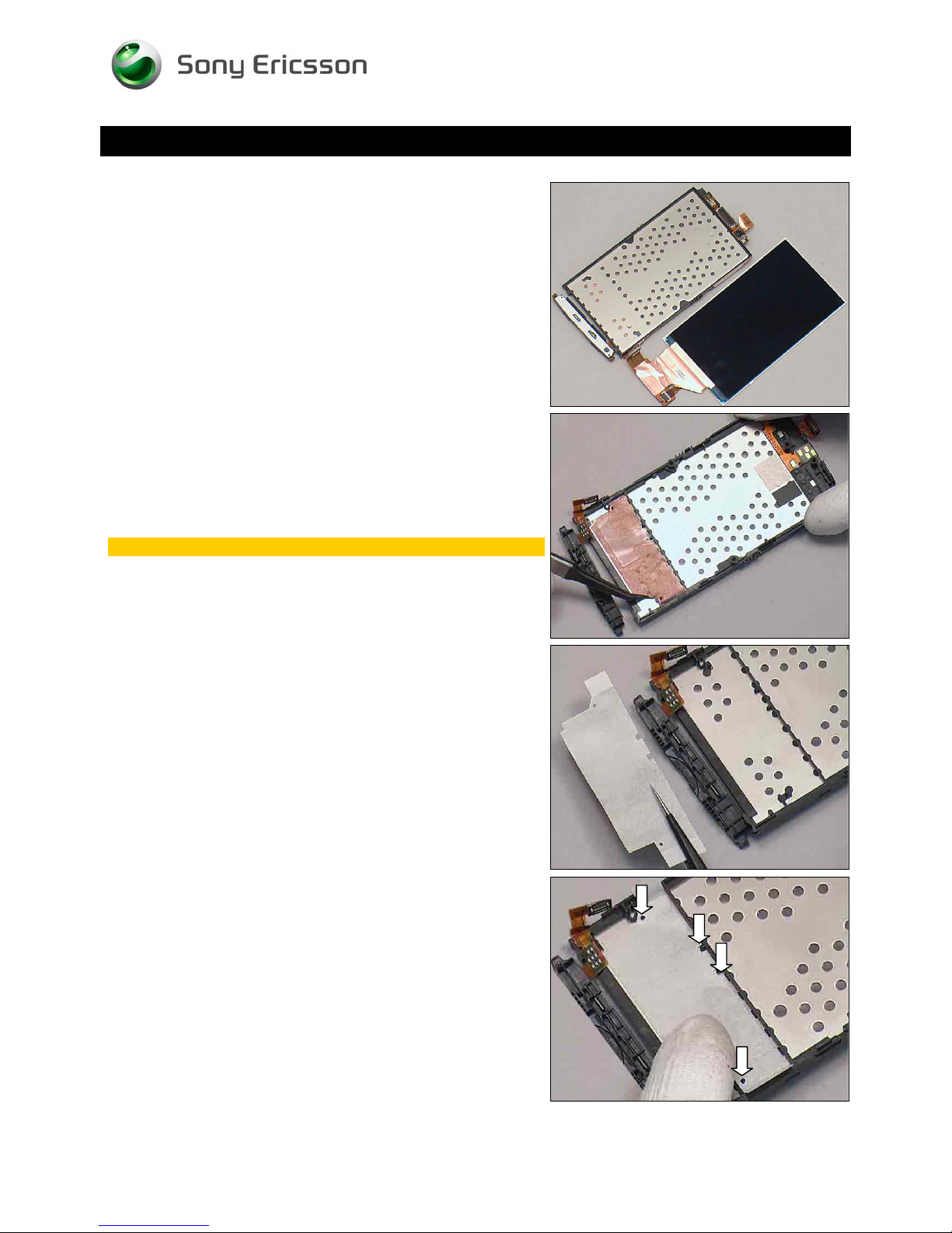
Separate the Display 4.0 TFT from the Unit.
Working Instruction Repair Instruction Mechanical/
Peel off the Adhesive Frame Sub Assembly by using a Flex
Film Assembly Tool.
Scrap! Not to be reused!
INSTALLATION
Put a new Adhesive Frame Sub Assembly in place.
Fix it align with the guiding poles as shown.
1230-2324 Rev 6
Sony Ericsson Mobile Communications AB – Company Internal
33(81)
Page 34
Replacement: Display 4.0 TFT
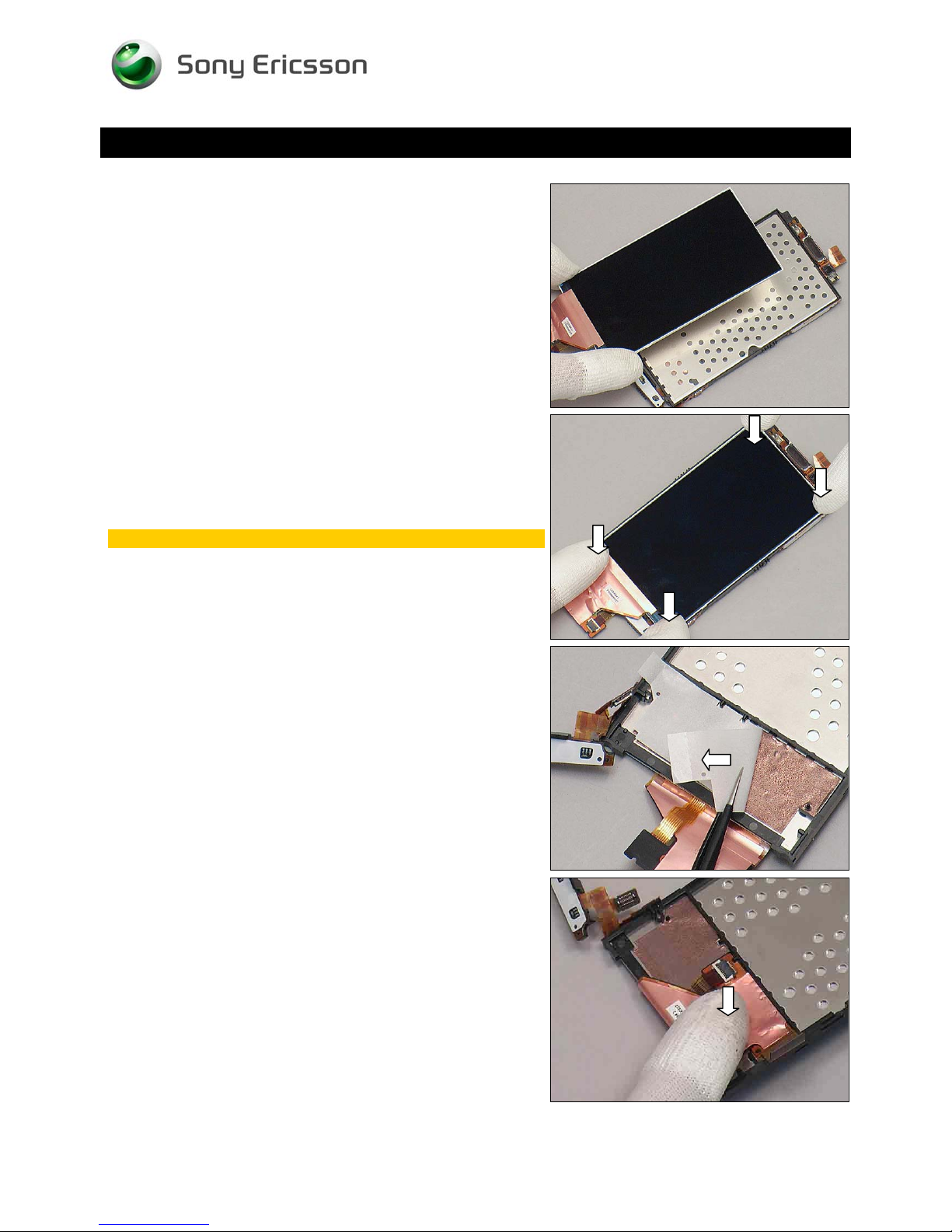
Place the Display 4.0 TFT in place.
Working Instruction Repair Instruction Mechanical/
Press to secure its position.
Do not touch the screen.
Peel off the protect film of the Adhesive Frame Sub
Assembly.
Fix the FPC on the Adhesive Frame Sub Assembly aligns
guiding poles.
1230-2324 Rev 6
Sony Ericsson Mobile Communications AB – Company Internal
34(81)
Page 35
Replacement
4.17 Frame Sub Assembly
Follow the 3.1 – 3.6 Disassembly instructions!
Prepare a new Frame Sub Assembly.
Follow the 5.1 – 5.6 Reassembly instructions!
Working Instruction Repair Instruction Mechanical/
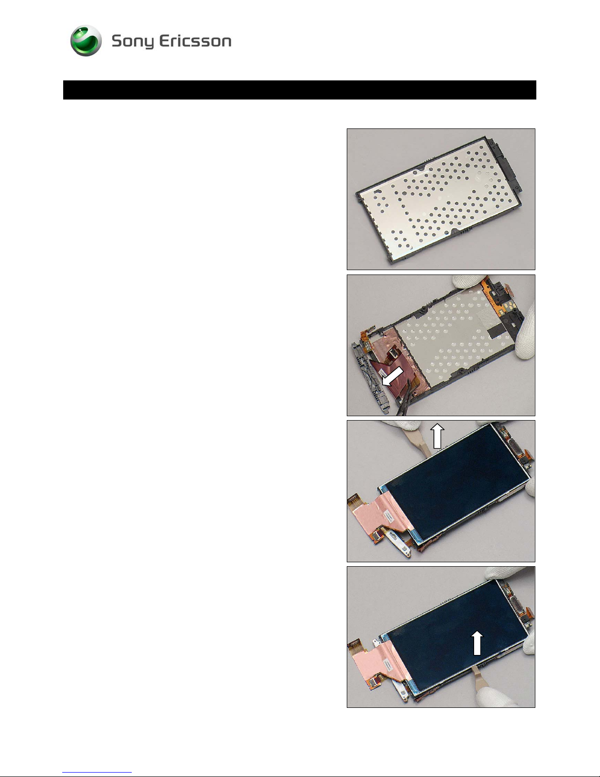
REMOVAL
Detach the FPC from the Adhesive Frame Sub Assembly.
Turn it over and release the Display 4.0 TFT with a Front
Opening Tool on the left side.
Do the same on the right side.
1230-2324 Rev 6
Sony Ericsson Mobile Communications AB – Company Internal
35(81)
Page 36
Working Instruction Repair Instruction Mechanical/
Replacement: Frame Sub Assembly
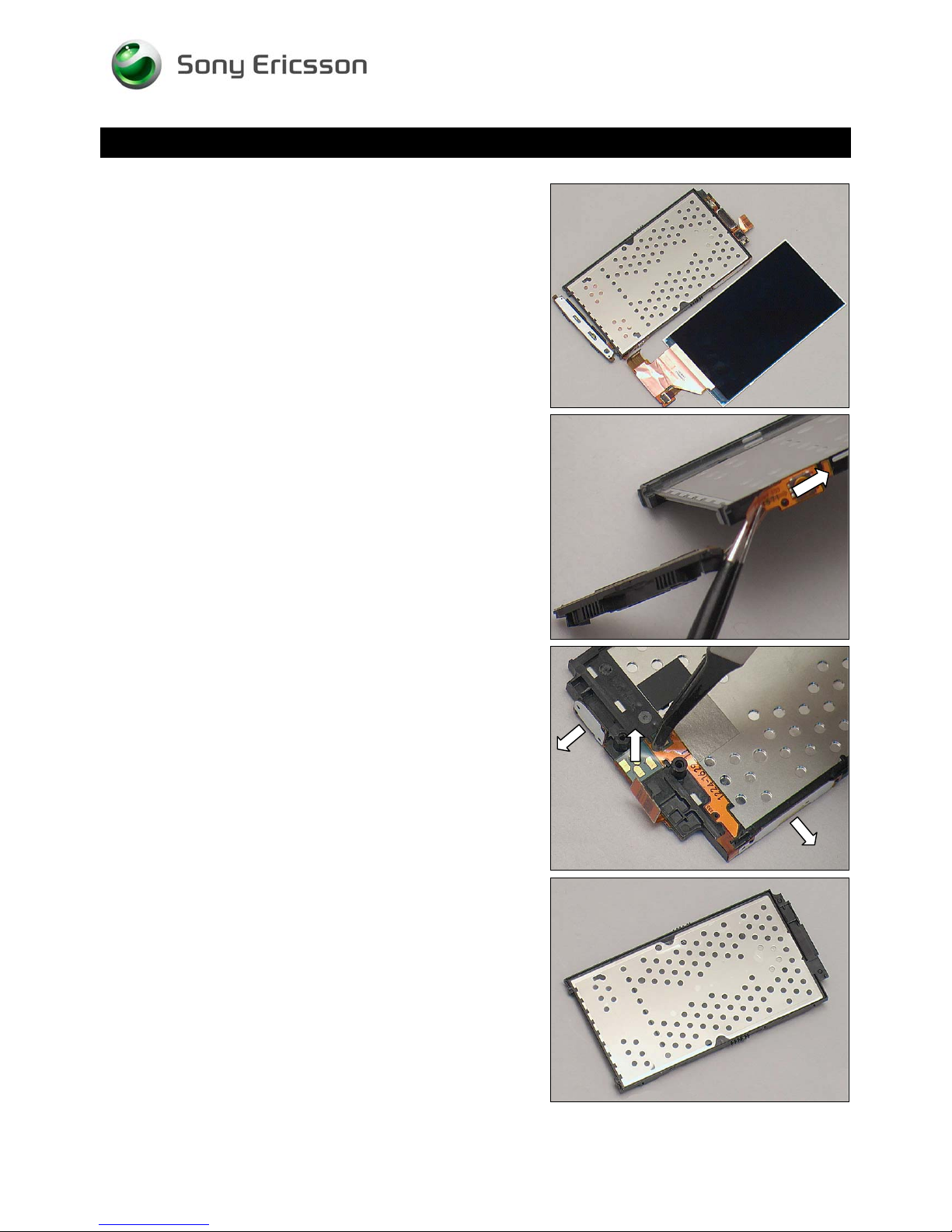
Separate the Display 4.0 TFT from the Frame Sub
Assembly.
Peel off the Main Key FPC from the Frame Sub Assembly.
Detach the Receiver FPC from the frame by using a Flex
Film Assembly Tool as shown.
INSTALLATION
Place a new Frame Sub Assembly.
1230-2324 Rev 6
Sony Ericsson Mobile Communications AB – Company Internal
36(81)
Page 37
Working Instruction Repair Instruction Mechanical/
Replacement: Frame Sub Assembly
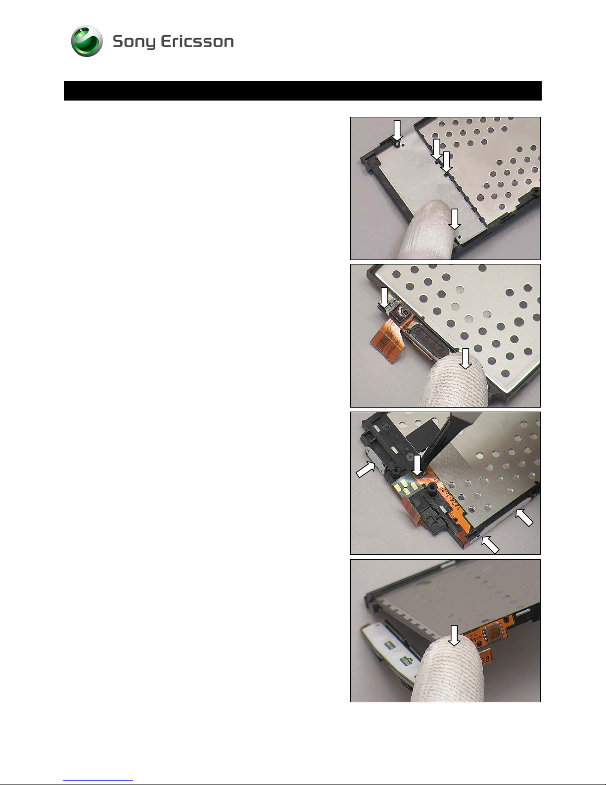
Attach a new Adhesive Frame Sub Assembly onto the
Frame Sub Assembly align guiding poles.
Attach a new Receiver onto the Frame Sub Assembly
aligned with the guiding poles.
Turn over the FPC and press the keys/pads aligned with the
guiding poles as shown
Attach the Main Key FPC Unit onto the Frame Sub
Assembly aligned with the guiding poles.
1230-2324 Rev 6
Sony Ericsson Mobile Communications AB – Company Internal
37(81)
Page 38
Working Instruction Repair Instruction Mechanical/
Replacement: Frame Sub Assembly
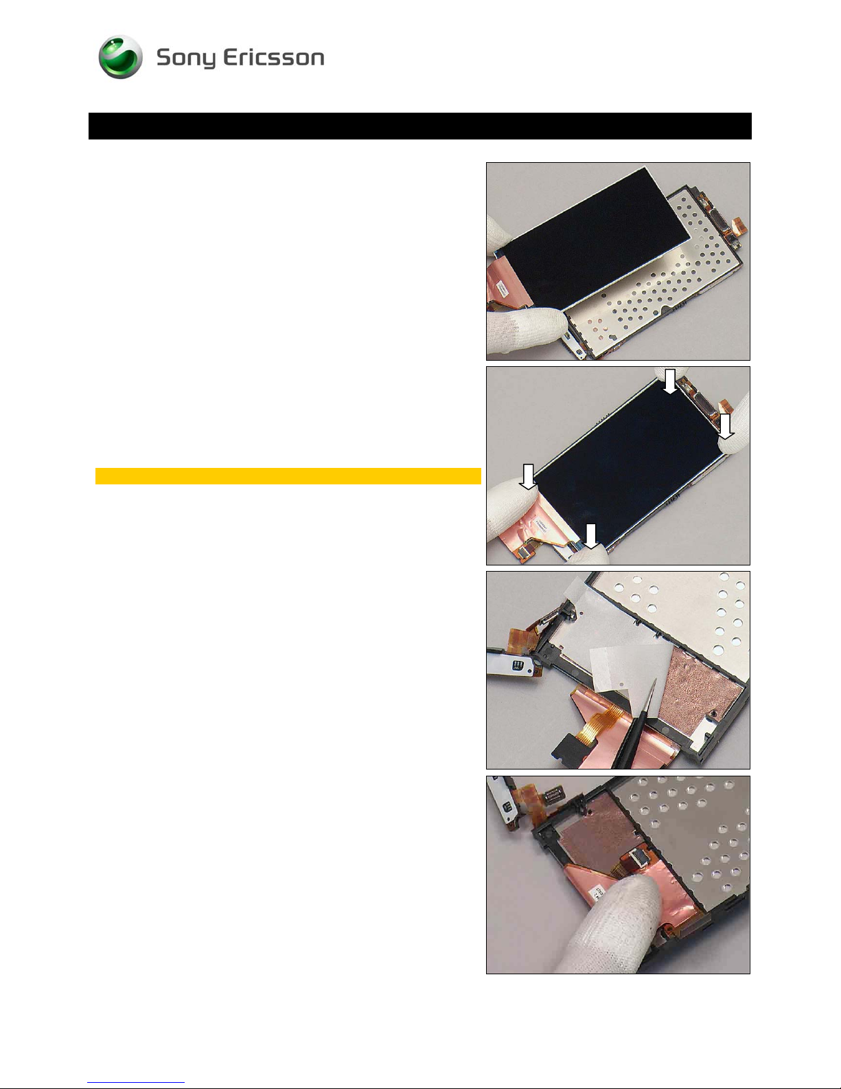
Place the Display 4.0 TFT in place.
Press to secure its position.
Do not touch the screen.
Turn over the Unit and peel off the protect film of the
Adhesive Frame Sub Assembly.
Fix the FPC on the Adhesive Frame Sub Assembly aligns
guiding poles.
1230-2324 Rev 6
Sony Ericsson Mobile Communications AB – Company Internal
38(81)
Page 39
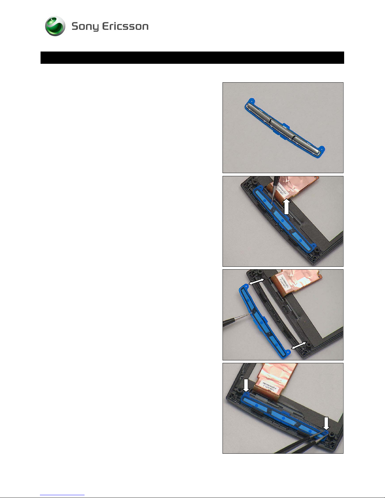
Replacement
4.18 Key Main
Follow the 3.1 – 3.6 Disassembly instructions!
Prepare a new Key Main.
Follow the 5.1 – 5.6 Reassembly instructions!
Working Instruction Repair Instruction Mechanical/
REMOVAL
Lift to remove by using a pair of tweezers.
INSTALLATION
Place a new Key Main in the proper direction into the slot.
Fix the Key Main on the guiding pole by using a pair of
tweezers.
1230-2324 Rev 6
Sony Ericsson Mobile Communications AB – Company Internal
39(81)
Page 40
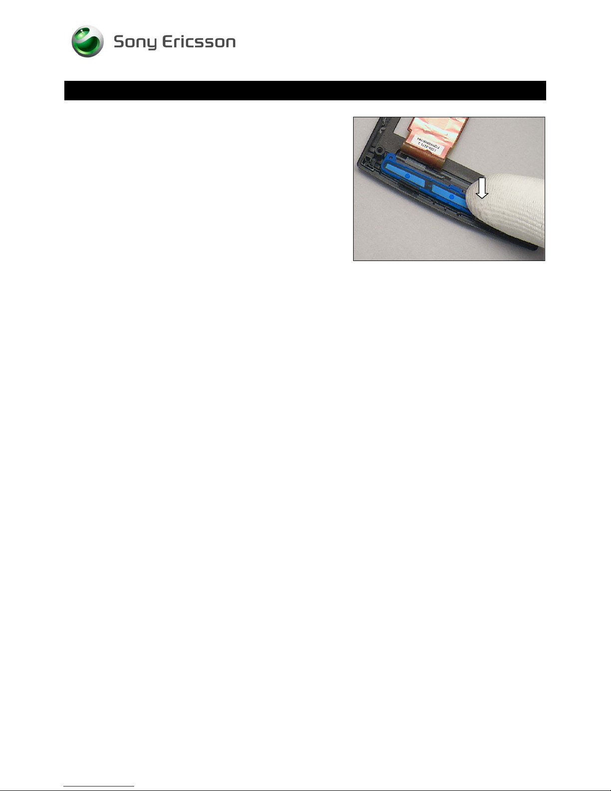
Replacement: Key Main
Press along to secure its position.
Working Instruction Repair Instruction Mechanical/
1230-2324 Rev 6
Sony Ericsson Mobile Communications AB – Company Internal
40(81)
Page 41
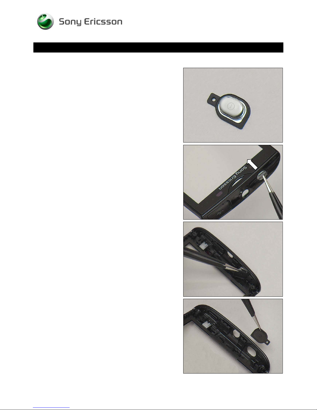
Replacement
4.19 Key On/Off
Follow the 3.1 – 3.6 Disassembly instructions!
Prepare a new Key On/Off.
Follow the 5.1 – 5.6 Reassembly instructions!
Working Instruction Repair Instruction Mechanical/
REMOVAL
Push from the outside with a pair of tweezers.
Remove the Key On/Off from the inside.
INSTALLATION
Place the Key On/Off with proper direction into the slot.
1230-2324 Rev 6
Sony Ericsson Mobile Communications AB – Company Internal
41(81)
Page 42
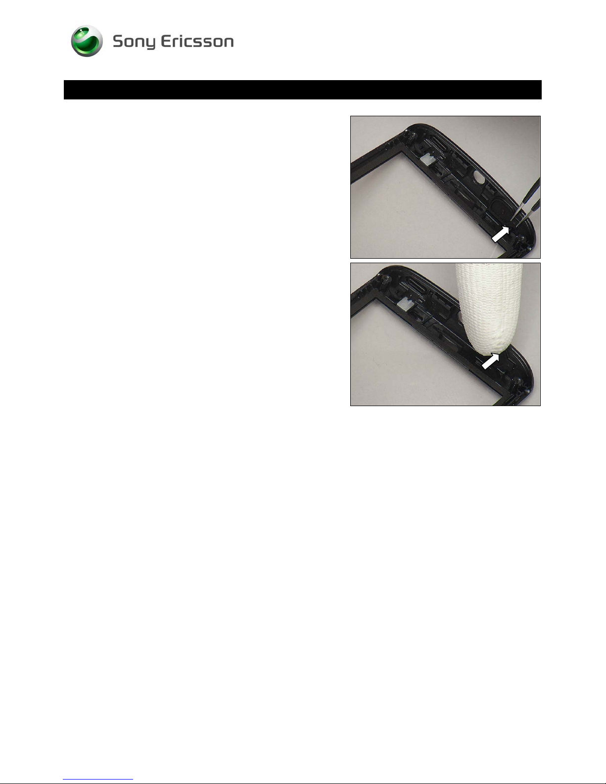
Replacement: Key On/Off
Fix the Key On/Off to the guiding pole by using a pair of
tweezers.
Working Instruction Repair Instruction Mechanical/
Press to secure its position
1230-2324 Rev 6
Sony Ericsson Mobile Communications AB – Company Internal
42(81)
Page 43
Replacement
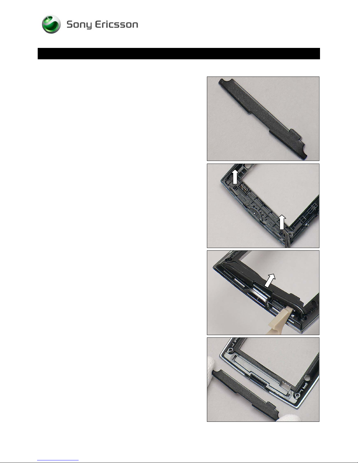
4.20 Main Antenna
Follow the 3.1 – 3.3 Disassembly instructions!
Prepare a new Main Antenna.
Follow the 5.4– 5.6 Reassembly instructions!
Working Instruction Repair Instruction Mechanical/
REMOVAL
Push to release the two hooks from inside of the Rear Cover
Assy by using a Flex Film Assembly Tool.
Detach carefully and remove it.
INSTALLATION
Put a new Main Antenna in place.
1230-2324 Rev 6
Sony Ericsson Mobile Communications AB – Company Internal
43(81)
Page 44
Replacement: Main Antenna
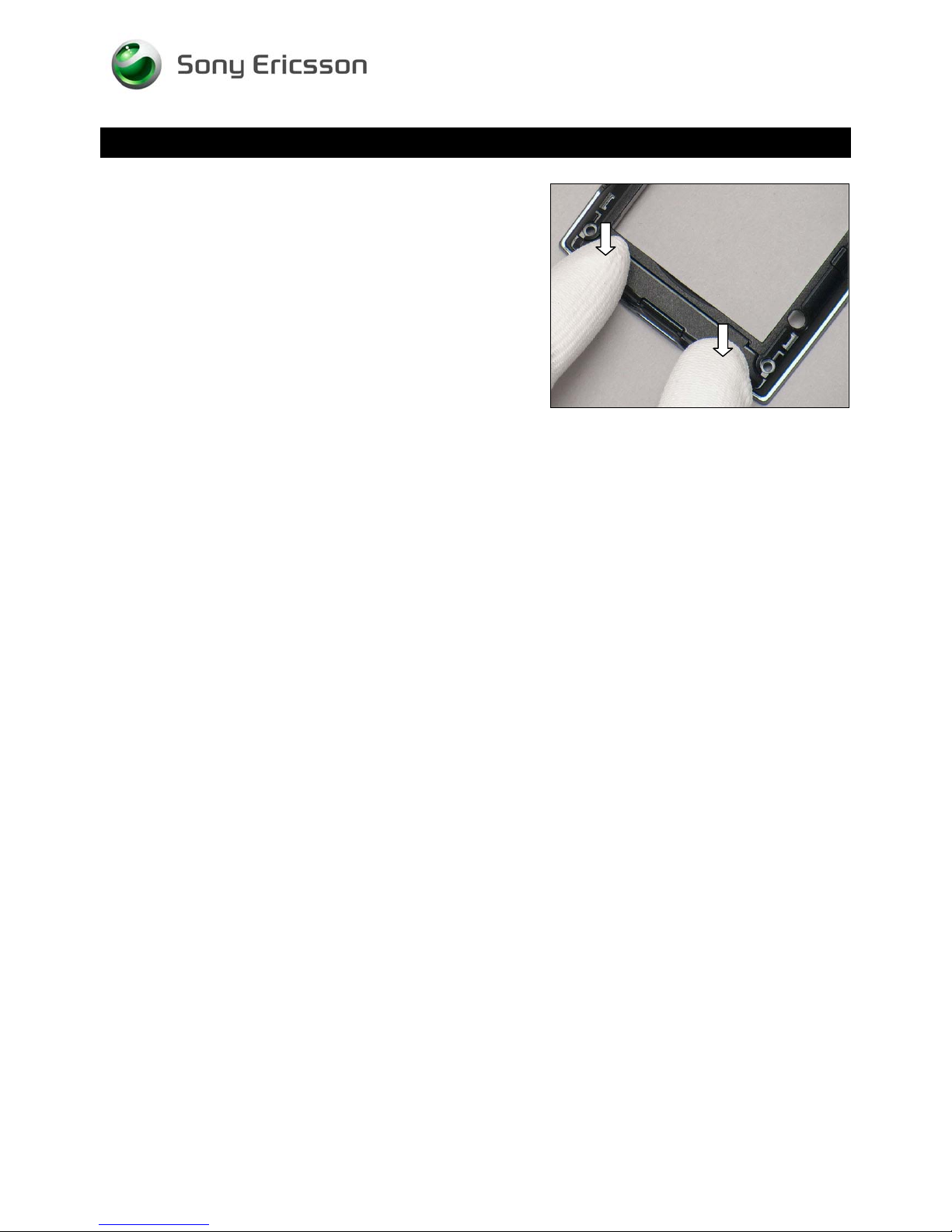
Press to snap the two hooks of Main Antenna.
Working Instruction Repair Instruction Mechanical/
1230-2324 Rev 6
Sony Ericsson Mobile Communications AB – Company Internal
44(81)
Page 45
Replacement
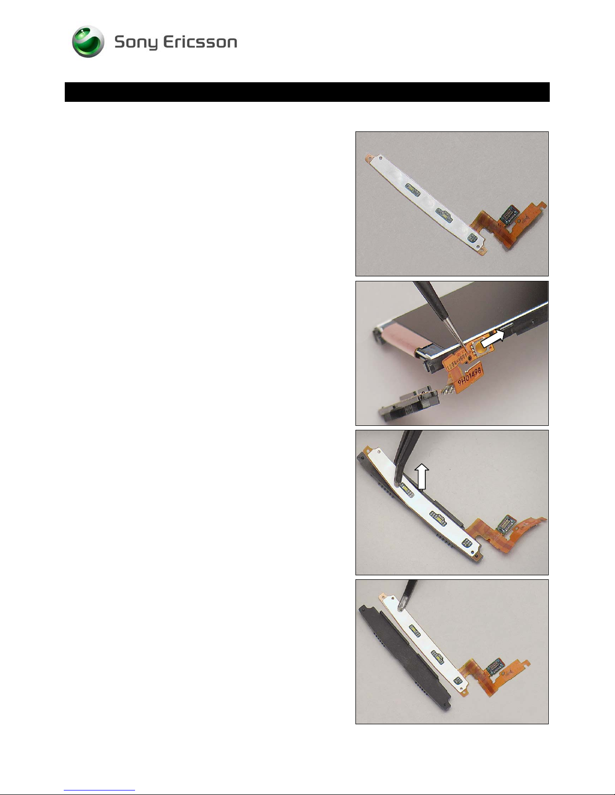
4.21 Main Key FPC
Follow the 3.1 – 3.6 Disassembly instructions!
Prepare a new Main Key FPC.
Follow the 5.1 – 5.6 Reassembly instructions!
Working Instruction Repair Instruction Mechanical/
REMOVAL
Peel off the Main Key Unit from the Frame Sub Assembly.
Detach the Main Key FPC from the Main Key Frame.
INSTALLATION
Place a new Main Key FPC in place.
1230-2324 Rev 6
Sony Ericsson Mobile Communications AB – Company Internal
45(81)
Page 46
Working Instruction Repair Instruction Mechanical/
Replacement: Main Key FPC
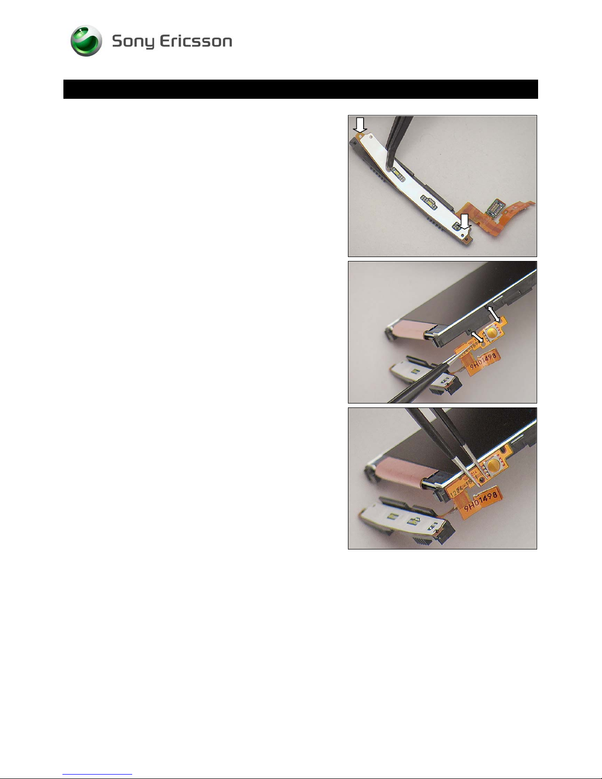
Attach the Main Key FPC onto the Main Key Frame aligns
two guiding poles.
Attach it onto the Frame Sub Assembly aligned with two
guiding poles as shown.
Press to secure its attachment.
1230-2324 Rev 6
Sony Ericsson Mobile Communications AB – Company Internal
46(81)
Page 47
Working Instruction Repair Instruction Mechanical/
Replacement
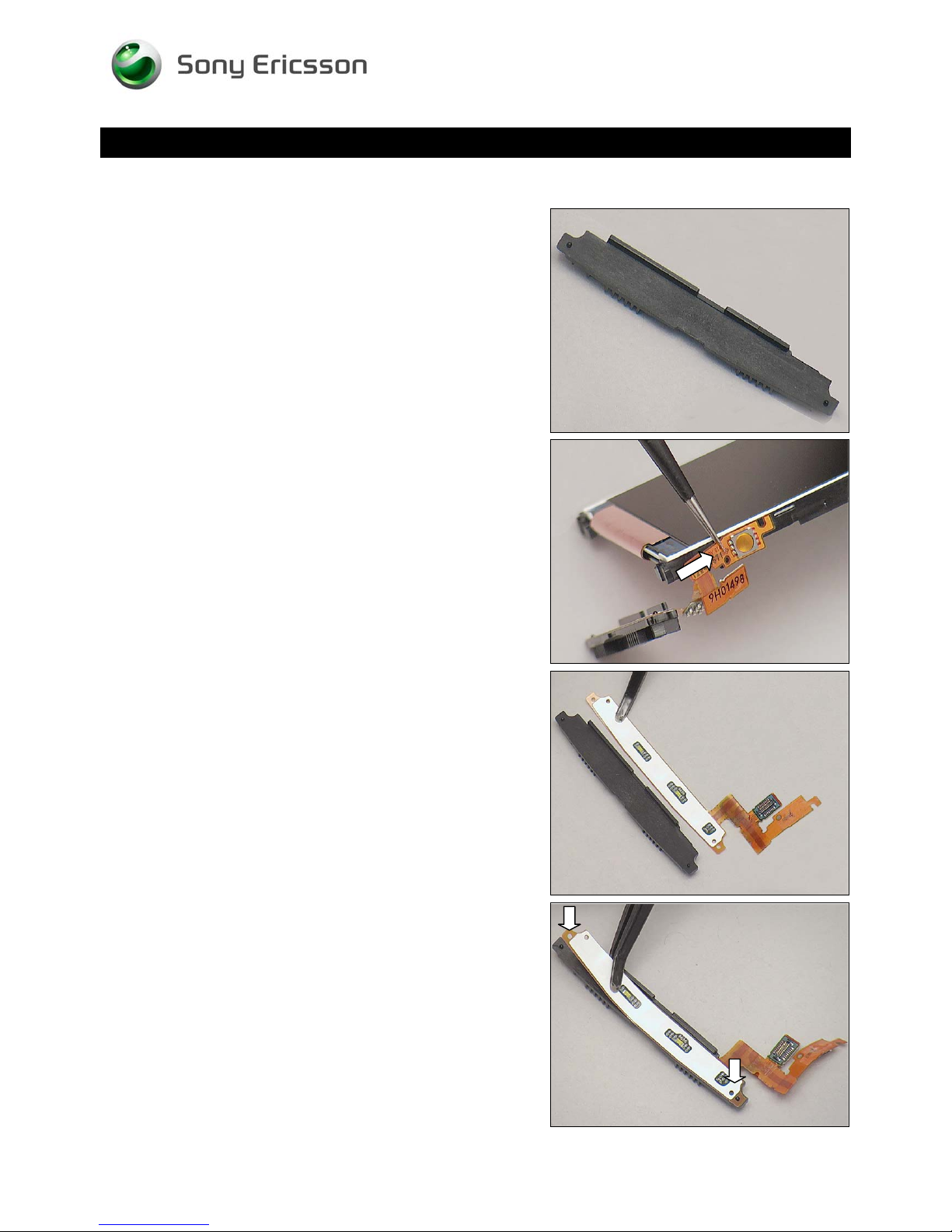
4.22 Main Key Frame
Follow the 3.1 – 3.6 Disassembly instructions!
Prepare a new Main Key Frame and a new Main Key FPC.
Follow the 5.1 – 5.6 Reassembly instructions!
REMOVAL
Peel it off the Main Key FPC from the Frame Sub Assembly.
INSTALLATION
Place the a new Main Key Frame and a new Main Key FPC
in place.
Attach the Main Key FPC onto the Main Key Frame aligns
two guiding poles.
1230-2324 Rev 6
Sony Ericsson Mobile Communications AB – Company Internal
47(81)
Page 48
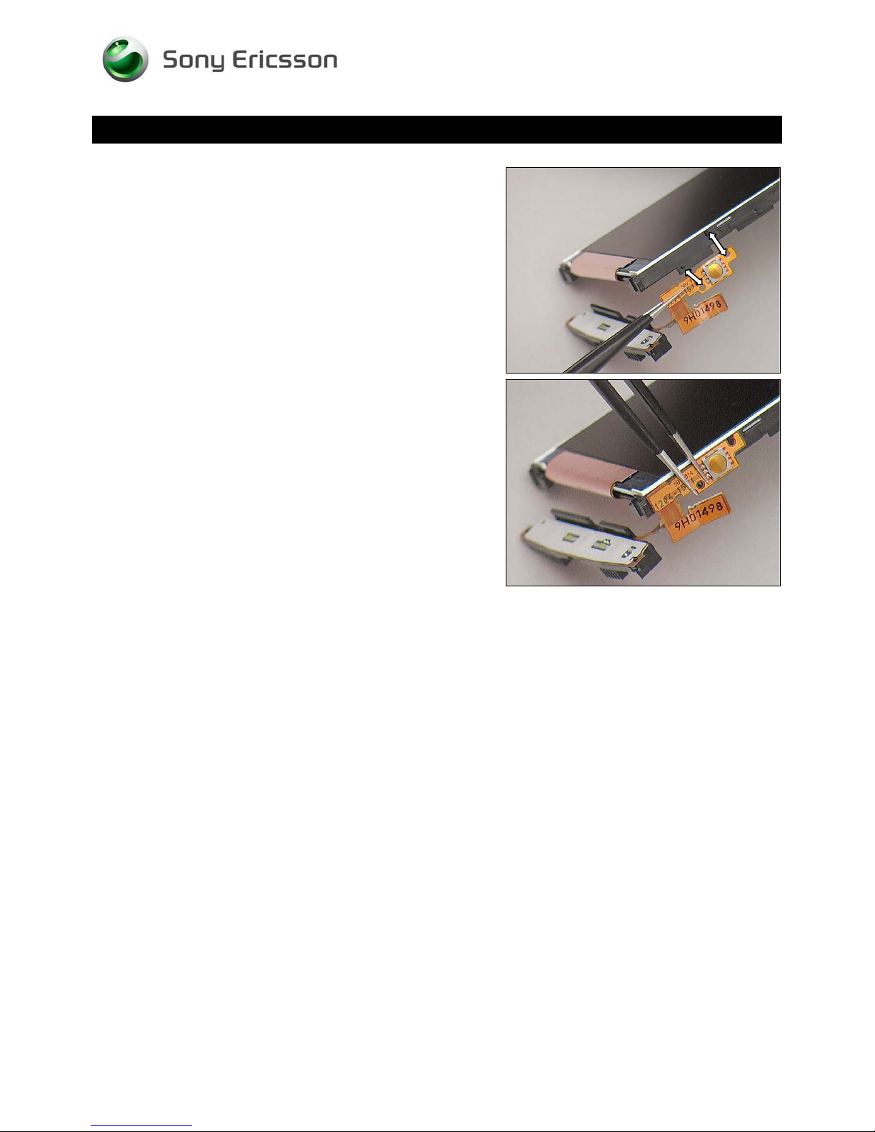
Replacement: Main Key Frame
Attach it onto the Frame Sub Assembly aligned with two
guiding poles as shown.
Working Instruction Repair Instruction Mechanical/
Press to secure its attachment.
1230-2324 Rev 6
Sony Ericsson Mobile Communications AB – Company Internal
48(81)
Page 49
Working Instruction Repair Instruction Mechanical/
Replacement
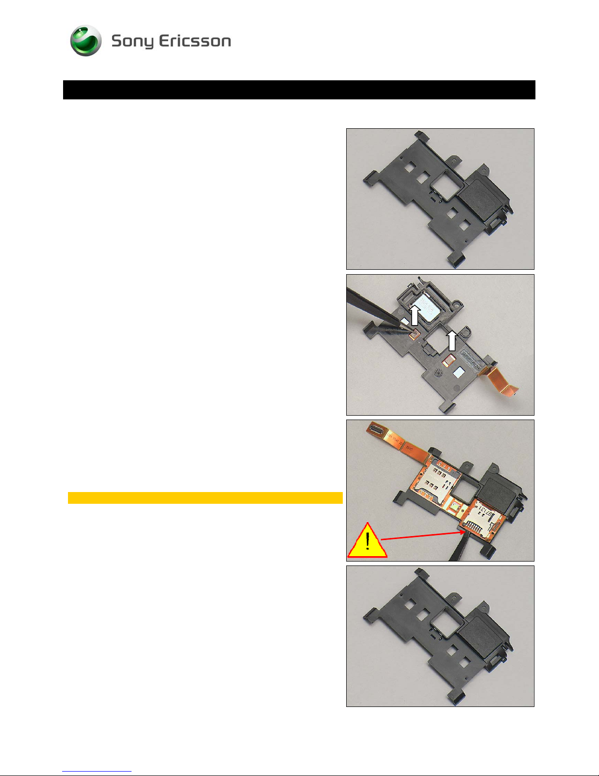
4.23 Non-Celler Antenna Speaker Box
Follow the 3.1 – 3.4 Disassembly instructions!
Prepare a new Non-Celler Antenna Speaker Box
Follow the 5.3 – 5.6 Reassembly instructions!
REMOVAL
Remove the two Conductive Gaskets.
Detach and remove the SIM and MicroSD FPC gently.
Be careful not to damage the SIM and MicroSD FPC
INSTALLATION
Put a new Non-Celler Antenna Speaker Box in place.
1230-2324 Rev 6
Sony Ericsson Mobile Communications AB – Company Internal
49(81)
Page 50
Working Instruction Repair Instruction Mechanical/
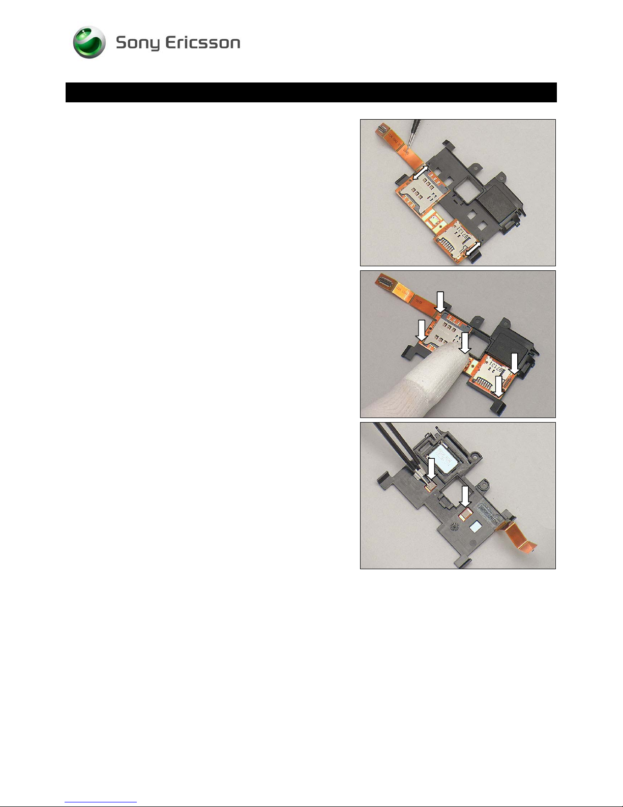
Replacement: Non-Celler Antenna Speaker Box
INSTALLATION
Put the SIM and MicroSD FPC align with the two guiding
poles of the Non-Celler Antenna Speaker Box.
Attach the SIM and MicroSD FPC aligns guiding poles.
Attach two new Conductive Gaskets onto the Unit.
1230-2324 Rev 6
Sony Ericsson Mobile Communications AB – Company Internal
50(81)
Page 51
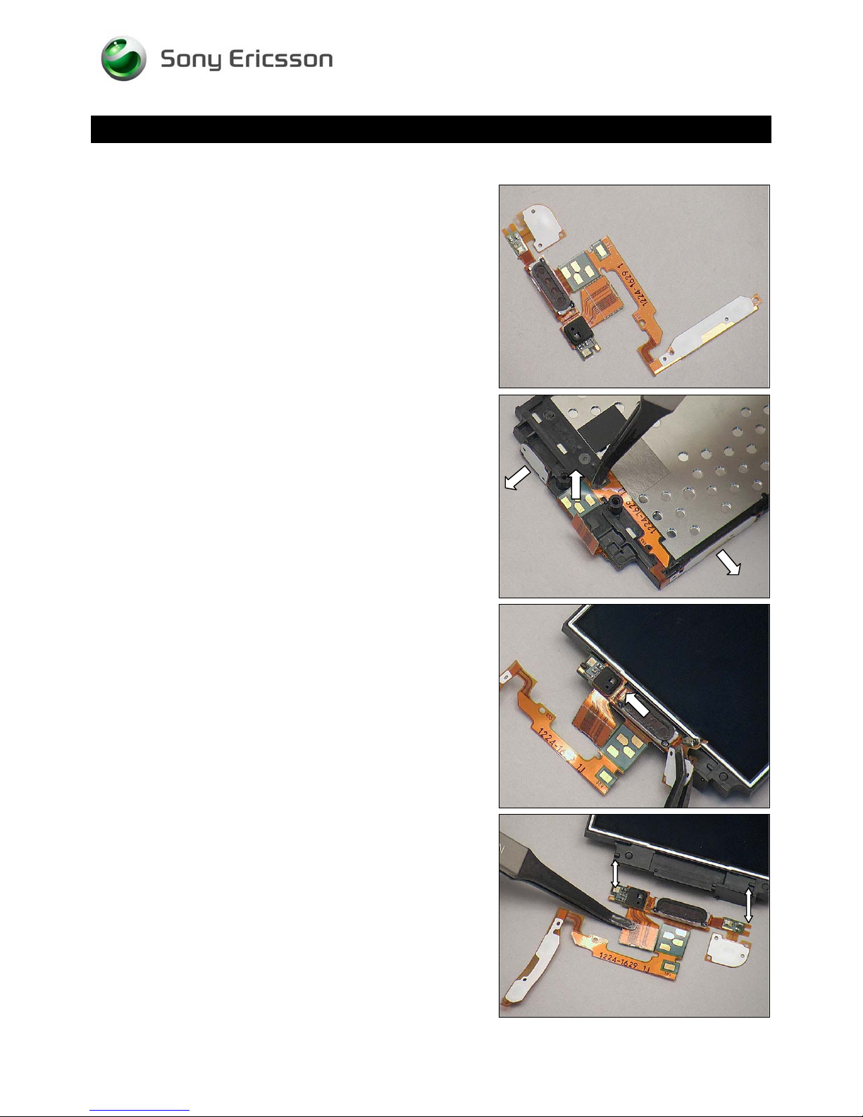
Replacement
4.24 Receiver FPC
Follow the 3.1 – 3.6 Disassembly instructions!
Prepare a new Receiver FPC.
Follow the 5.1 – 5.6 Reassembly instructions!
Working Instruction Repair Instruction Mechanical/
REMOVAL
Detach the keys/pads from the frame by using a Flex Film
Assembly Tool as shown.
Detach the speaker carefully.
INSTALLATION
Place the Receiver FPC in place
1230-2324 Rev 6
Sony Ericsson Mobile Communications AB – Company Internal
51(81)
Page 52
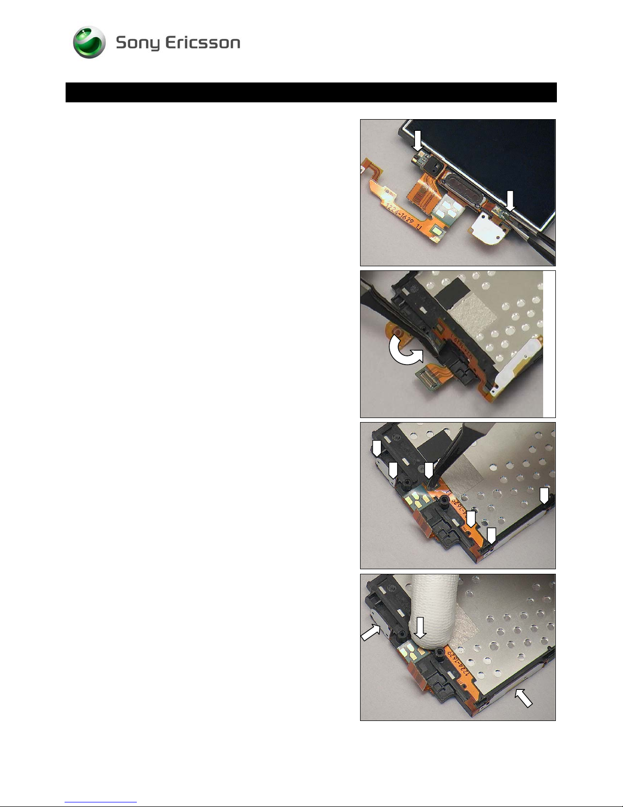
Working Instruction Repair Instruction Mechanical/
Replacement: Receiver FPC
Attach the Receiver FPC aligned with the two guiding poles.
Turn over the FPC.
Put the keys/pads aligned with the guiding poles as shown.
Press to secure attachment.
1230-2324 Rev 6
Sony Ericsson Mobile Communications AB – Company Internal
52(81)
Page 53
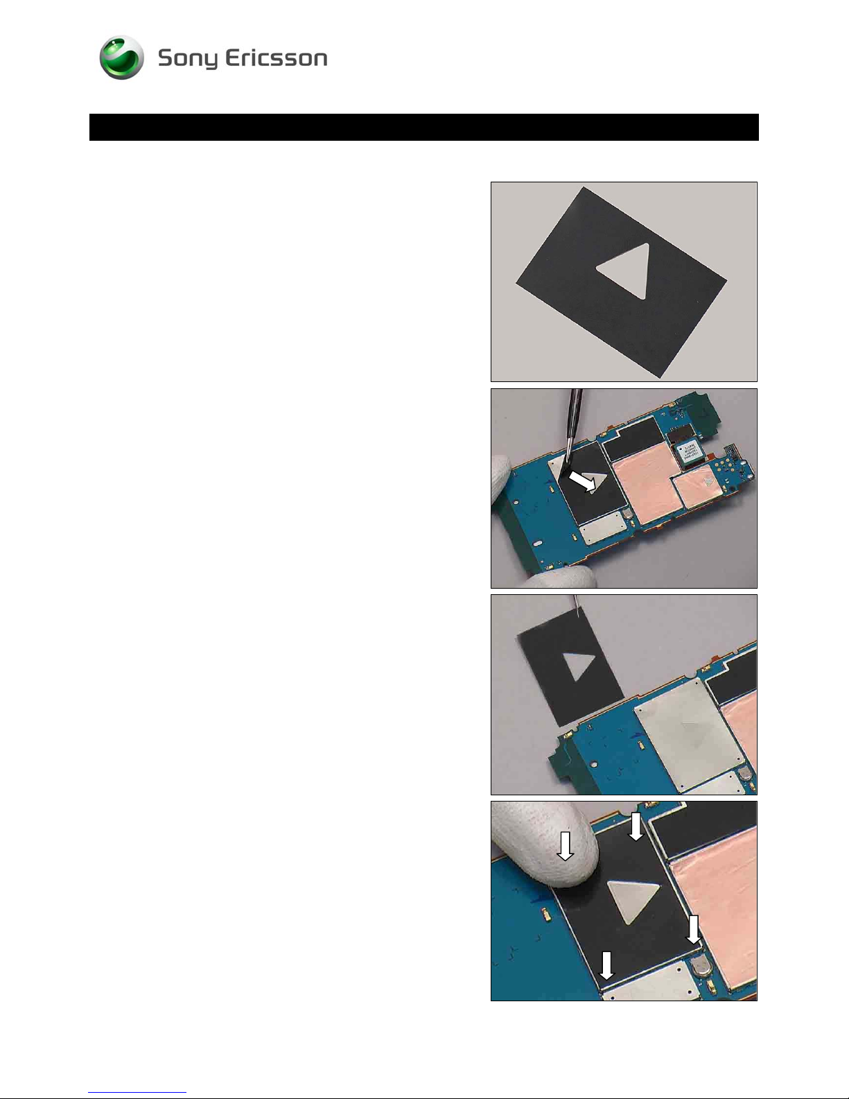
Working Instruction Repair Instruction Mechanical/
Replacement
4.25 Shield Can MComp Sheet Lid A1
Follow the 3.1 – 3.5 Disassembly instructions!
Prepare a new Shield Can MComp Sheet Lid A1.
Follow the 5.2 – 5.6 Reassembly instructions!
REMOVAL
Detach the Shield Can MComp Sheet Lid A1 from Main PBA
INSTALLATION
Put a new Shield Can MComp Sheet Lid A1 in place.
Press to secure its attachment.
1230-2324 Rev 6
Sony Ericsson Mobile Communications AB – Company Internal
53(81)
Page 54
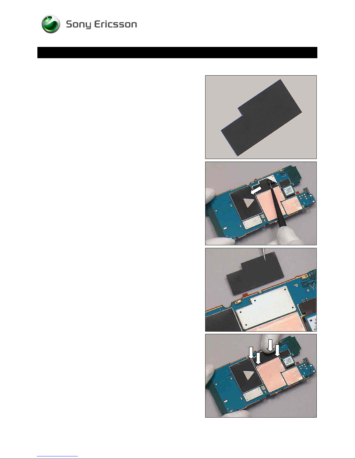
Working Instruction Repair Instruction Mechanical/
Replacement
4.26 Shield Can MComp Sheet Lid A3
Follow the 3.1 – 3.5 Disassembly instructions!
Prepare a new Shield Can MComp Sheet Lid A3.
Follow the 5.2 – 5.6 Reassembly instructions!
REMOVAL
Detach the Shield Can MComp Sheet Lid A3 from Main PBA
INSTALLATION
Put a new Shield Can MComp Sheet Lid A3 in place.
Press to secure its attachment.
1230-2324 Rev 6
Sony Ericsson Mobile Communications AB – Company Internal
54(81)
Page 55
Working Instruction Repair Instruction Mechanical/
Replacement
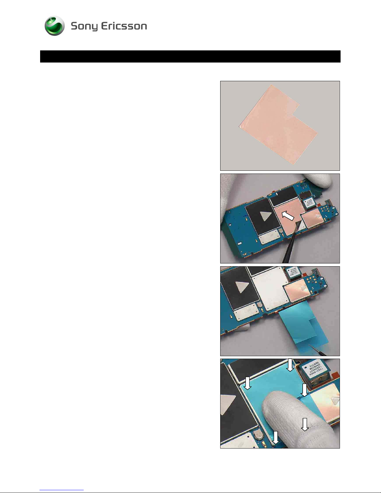
4.27 Shield Can MComp Sheet Lid A4
Follow the 3.1 – 3.5 Disassembly instructions!
Prepare a new Shield Can MComp Sheet Lid A4.
Follow the 5.2 – 5.6 Reassembly instructions!
REMOVAL
Detach the Shield Can MComp Sheet Lid A4 from Main PBA
INSTALLATION
Put a new Shield Can MComp Sheet Lid A4 in place.
Press to secure its attachment.
1230-2324 Rev 6
Sony Ericsson Mobile Communications AB – Company Internal
55(81)
Page 56
Working Instruction Repair Instruction Mechanical/
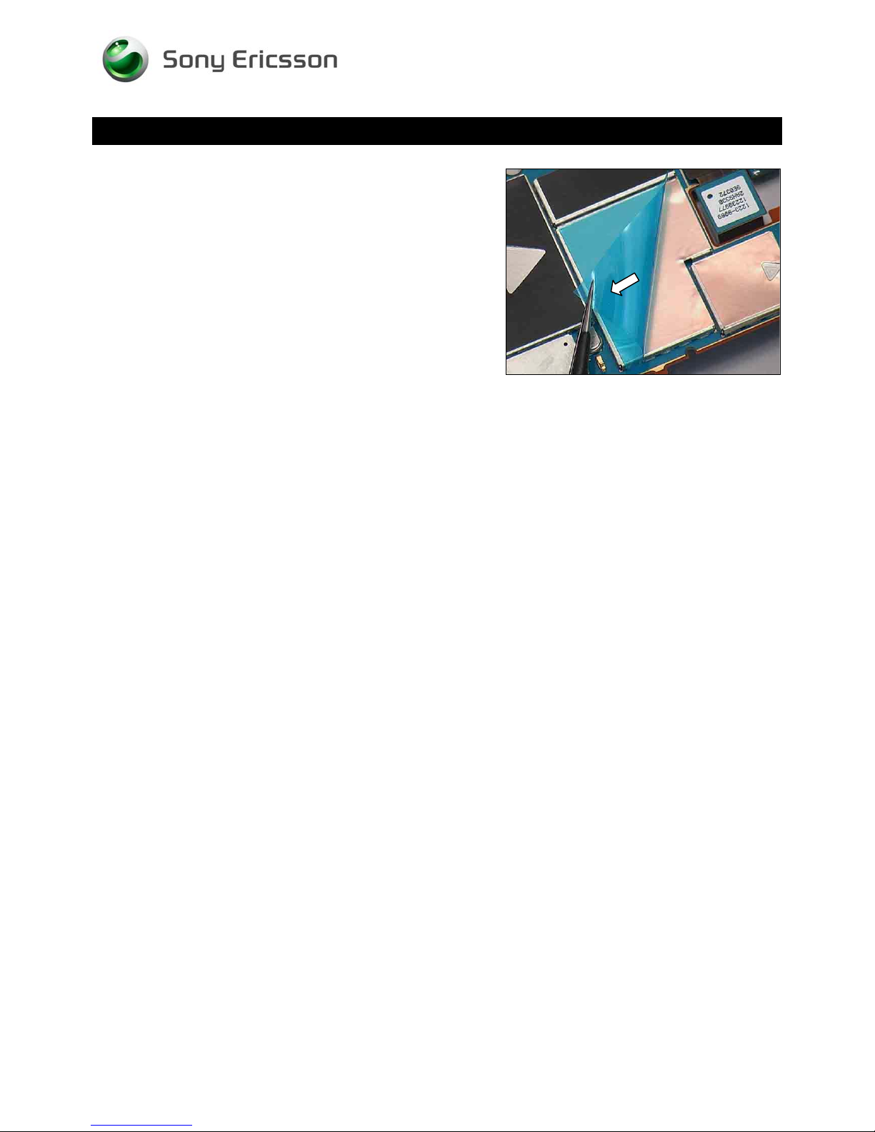
Replacement: Shield Can MComp Sheet Lid A4
Peel off the protect film.
1230-2324 Rev 6
Sony Ericsson Mobile Communications AB – Company Internal
56(81)
Page 57
Working Instruction Repair Instruction Mechanical/
Replacement
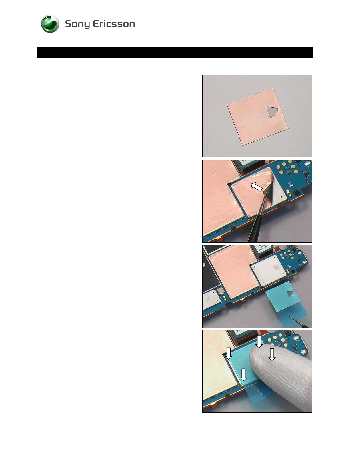
4.28 Shield Can MComp Sheet Lid A5
Follow the 3.1 – 3.5 Disassembly instructions!
Prepare a new Shield Can MComp Sheet Lid A5.
Follow the 5.2 – 5.6 Reassembly instructions!
REMOVAL
Detach the Shield Can MComp Sheet Lid A5 from Main PBA
INSTALLATION
Put a new Shield Can MComp Sheet Lid A5 in place.
Press to secure its attachment.
1230-2324 Rev 6
Sony Ericsson Mobile Communications AB – Company Internal
57(81)
Page 58
Working Instruction Repair Instruction Mechanical/
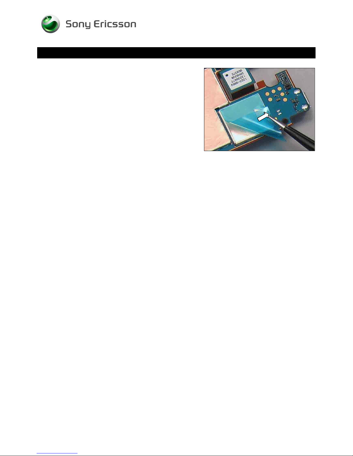
Replacement: Shield Can MComp Sheet Lid A5
Peel off the protect film.
1230-2324 Rev 6
Sony Ericsson Mobile Communications AB – Company Internal
58(81)
Page 59
Replacement
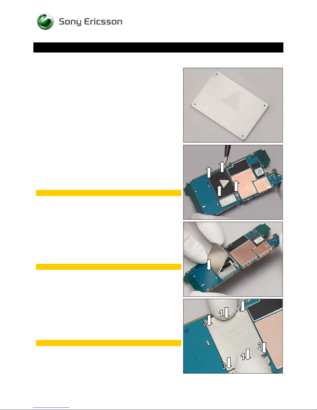
4.29 Shield Can Lid A1
Follow the 3.1 – 3.5 Disassembly instructions!
Prepare a new Shield Can Lid A1.
Follow the 5.2 – 5.6 Reassembly instructions!
Working Instruction Repair Instruction Mechanical/
REMOVAL
Unsnap the corners of the Shield Can Lid A1 with a pair of
tweezers and remove it.
Scrap! Cannot be reused!
INSTALLATION
Place a new Shield Can Lid A1 from lower side as shown.
Follow the assembly steps firmly!
Press to snap on both sides with fingers following the order
as the arrows shown.
Follow the assembly steps firmly!
1230-2324 Rev 6
Sony Ericsson Mobile Communications AB – Company Internal
59(81)
Page 60
Working Instruction Repair Instruction Mechanical/
Replacement: Shield Can Lid A1
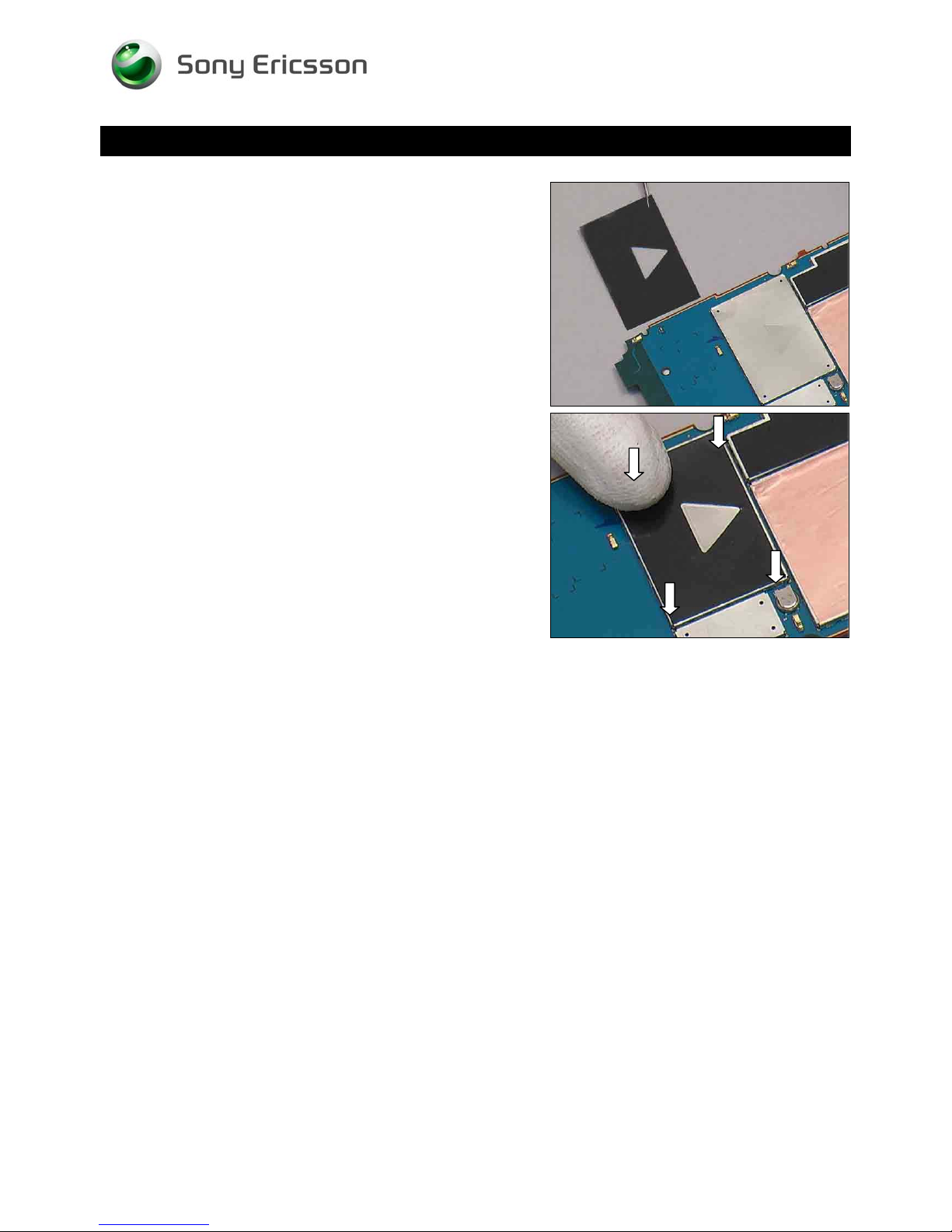
Put a new Shield Can MComp Sheet Lid A1 in place.
Press to secure its attachment.
1230-2324 Rev 6
Sony Ericsson Mobile Communications AB – Company Internal
60(81)
Page 61
Replacement
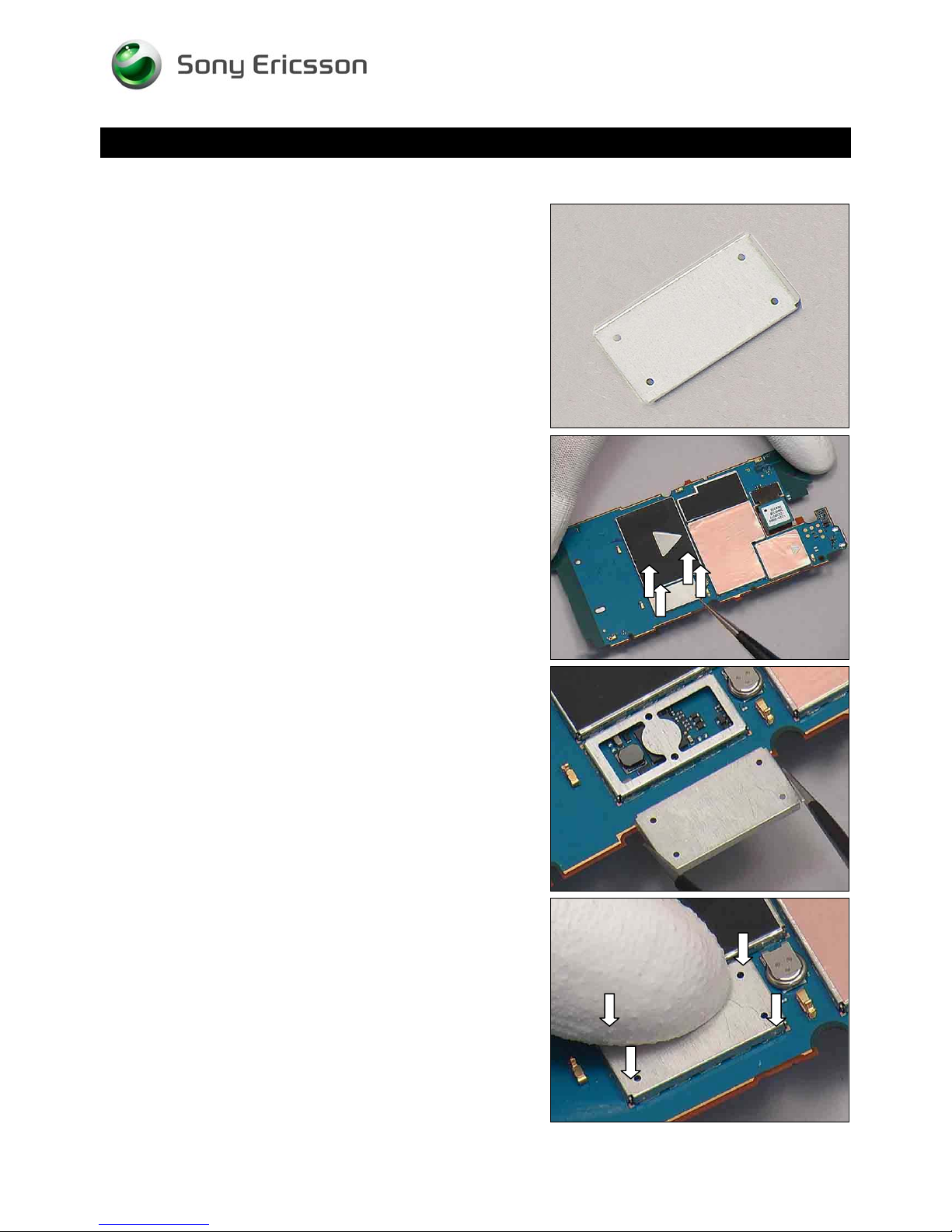
4.30 Shield Can Lid A2
Follow the 3.1 – 3.5 Disassembly instructions!
Prepare a new Shield Can Lid A2.
Follow the 5.2 – 5.6 Reassembly instructions!
Working Instruction Repair Instruction Mechanical/
REMOVAL
Unsnap the corners of the Shield Can Lid A2 with a pair of
tweezers and remove it.
INSTALLATION
Put a new Shield Can Lid A2 in place.
Press to snap it.
1230-2324 Rev 6
Sony Ericsson Mobile Communications AB – Company Internal
61(81)
Page 62
Replacement
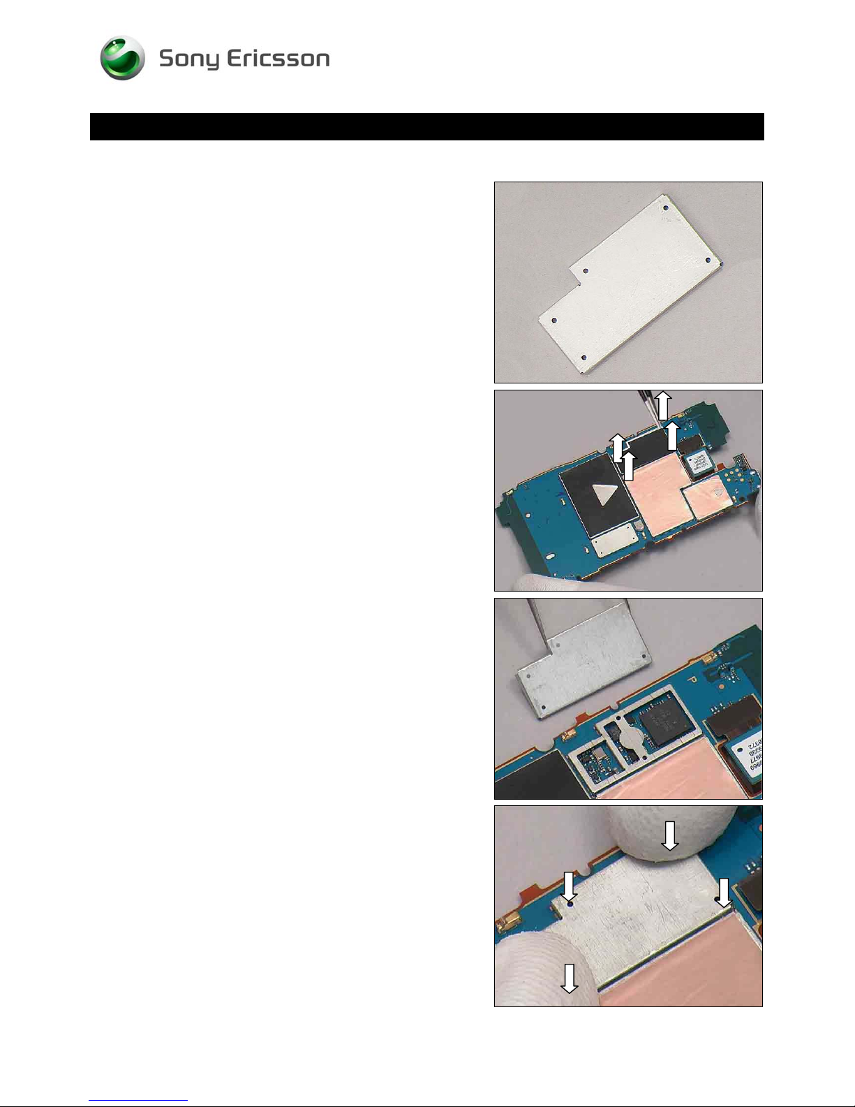
4.31 Shield Can Lid A3
Follow the 3.1 – 3.5 Disassembly instructions!
Prepare a new Shield Can Lid A3.
Follow the 5.2 – 5.6 Reassembly instructions!
Working Instruction Repair Instruction Mechanical/
REMOVAL
Unsnap the corners of the Shield Can Lid A3 with a pair of
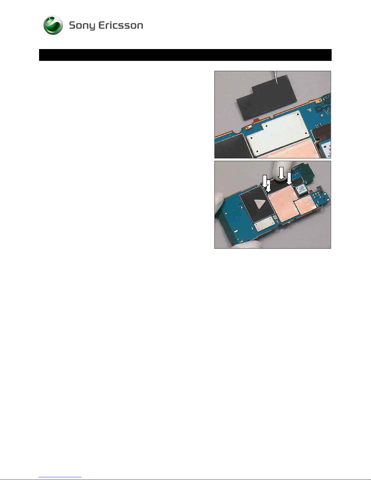
tweezers and remove it.
INSTALLATION
Put a new Shield Can Lid A3 in place.
Press to snap it.
1230-2324 Rev 6
Sony Ericsson Mobile Communications AB – Company Internal
62(81)
Page 63
Working Instruction Repair Instruction Mechanical/
Replacement: Shield Can Lid A3
Put a new Shield Can MComp Sheet Lid A3 in place.
Press to secure its attachment.
1230-2324 Rev 6
Sony Ericsson Mobile Communications AB – Company Internal
63(81)
Page 64
Replacement
4.32 Shield Can Lid A4
Follow the 3.1 – 3.5 Disassembly instructions!
Prepare a new Shield Can Lid A4.
Follow the 5.2 – 5.6 Reassembly instructions!
Working Instruction Repair Instruction Mechanical/
REMOVAL
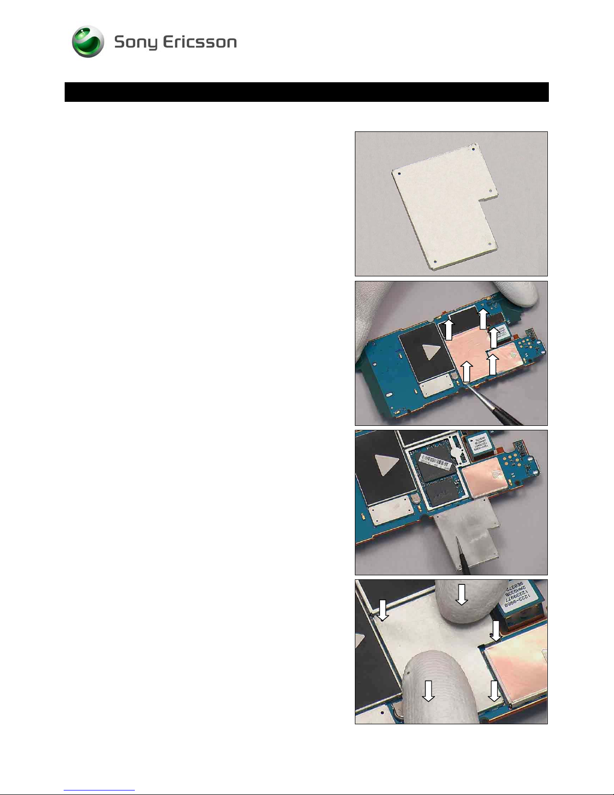
Unsnap the corners of the Shield Can Lid A4 with a pair of
tweezers and remove it.
INSTALLATION
Put a new Shield Can Lid A4 in place.
Press to snap it.
1230-2324 Rev 6
Sony Ericsson Mobile Communications AB – Company Internal
64(81)
Page 65
Working Instruction Repair Instruction Mechanical/
Replacement: Shield Can Lid A4
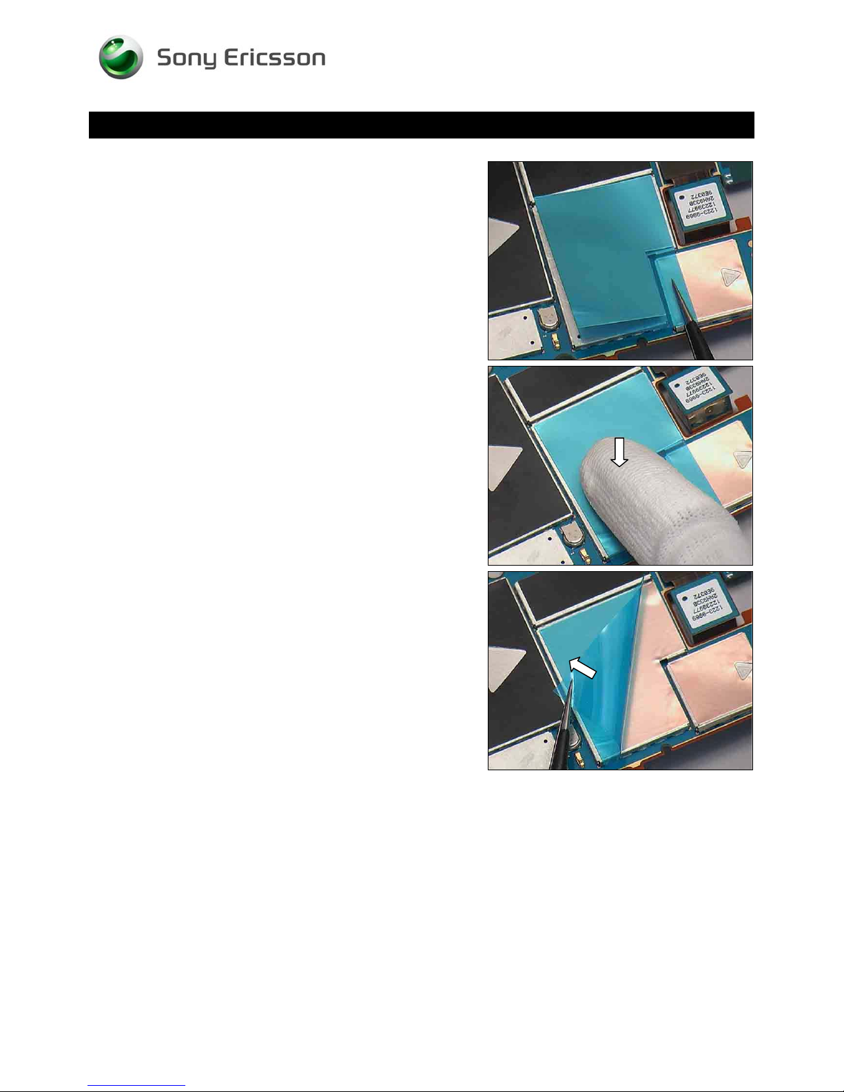
Put a new Shield Can MComp Sheet Lid A4 in place.
Press to secure its attachment.
Peel off the protect film.
1230-2324 Rev 6
Sony Ericsson Mobile Communications AB – Company Internal
65(81)
Page 66
Replacement
4.33 Shield Can Lid A5
Follow the 3.1 – 3.5 Disassembly instructions!
Prepare a new Shield Can Lid A5.
Follow the 5.2 – 5.6 Reassembly instructions!
Working Instruction Repair Instruction Mechanical/
REMOVAL
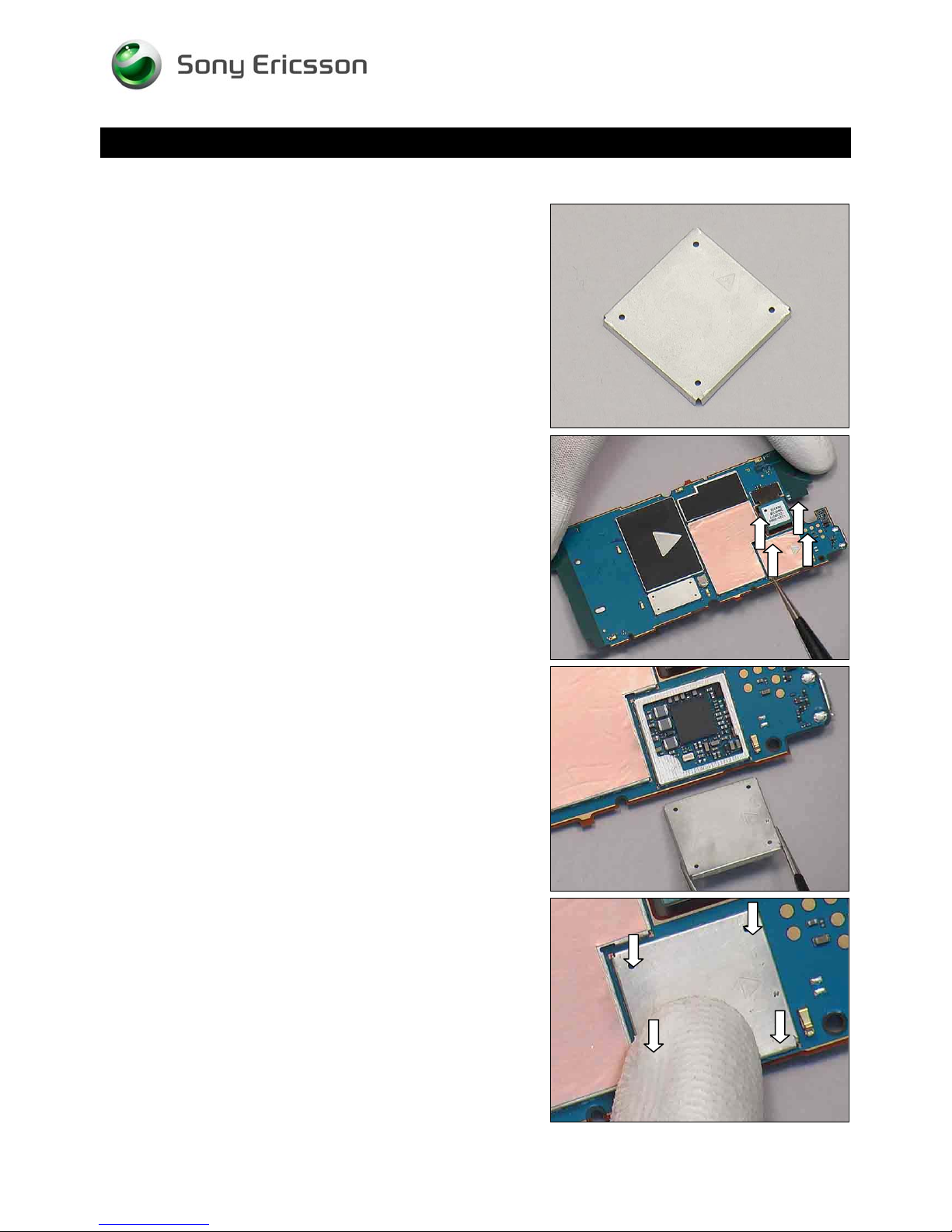
Unsnap the corners of the Shield Can Lid A5 with a pair of
tweezers and remove it.
INSTALLATION
Put a new Shield Can Lid A5 in place.
Press to snap it.
1230-2324 Rev 6
Sony Ericsson Mobile Communications AB – Company Internal
66(81)
Page 67
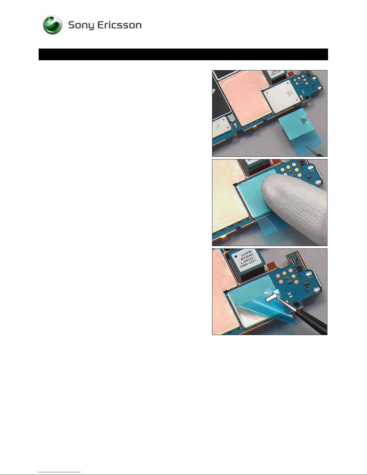
Working Instruction Repair Instruction Mechanical/
Replacement: Shield Can Lid A5
Put a new Shield Can MComp Sheet Lid A5 in place.
Press to secure its attachment.
Peel off the protect film.
1230-2324 Rev 6
Sony Ericsson Mobile Communications AB – Company Internal
67(81)
Page 68
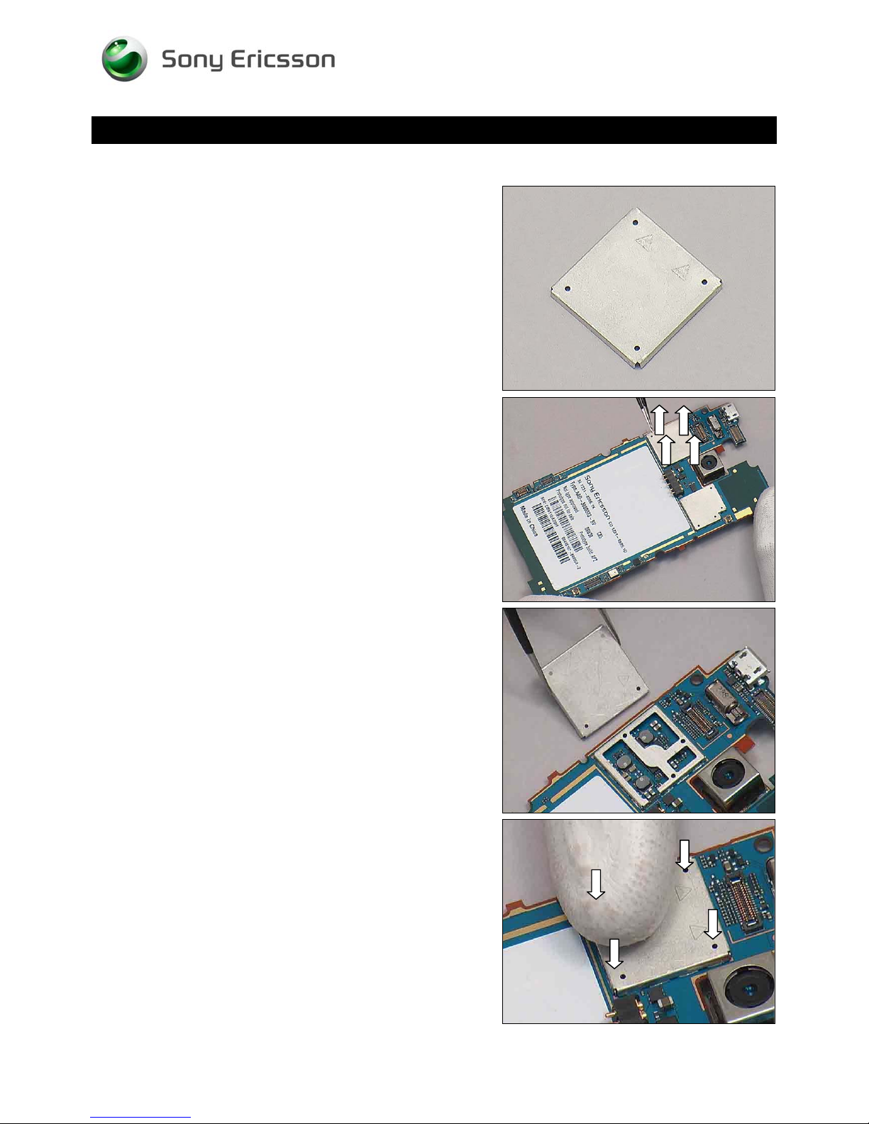
Replacement
4.34 Shield Can Lid B1
Follow the 3.1 – 3.5 Disassembly instructions!
Prepare a new Shield Can Lid B1.
Follow the 5.2 – 5.6 Reassembly instructions!
Working Instruction Repair Instruction Mechanical/
REMOVAL
Unsnap the corners of the Shield Can Lid B1 with a pair of
tweezers and remove it.
INSTALLATION
Put a new Shield Can Lid B1 in place.
Press to snap it.
1230-2324 Rev 6
Sony Ericsson Mobile Communications AB – Company Internal
68(81)
Page 69
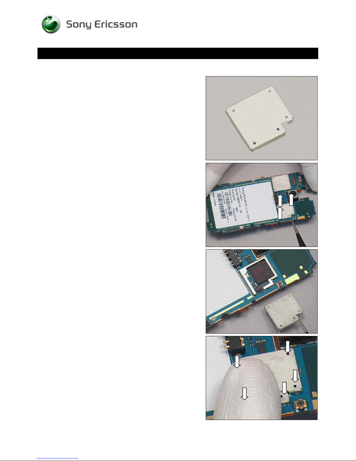
Replacement
4.35 Shield Can Lid B2
Follow the 3.1 – 3.5 Disassembly instructions!
Prepare a new Shield Can Lid B2.
Follow the 5.2 – 5.6 Reassembly instructions!
Working Instruction Repair Instruction Mechanical/
REMOVAL
Unsnap the corners of the Shield Can Lid B2 with a pair of
tweezers and remove it.
INSTALLATION
Put a new Shield Can Lid B2 in place.
Press to snap it.
1230-2324 Rev 6
Sony Ericsson Mobile Communications AB – Company Internal
69(81)
Page 70
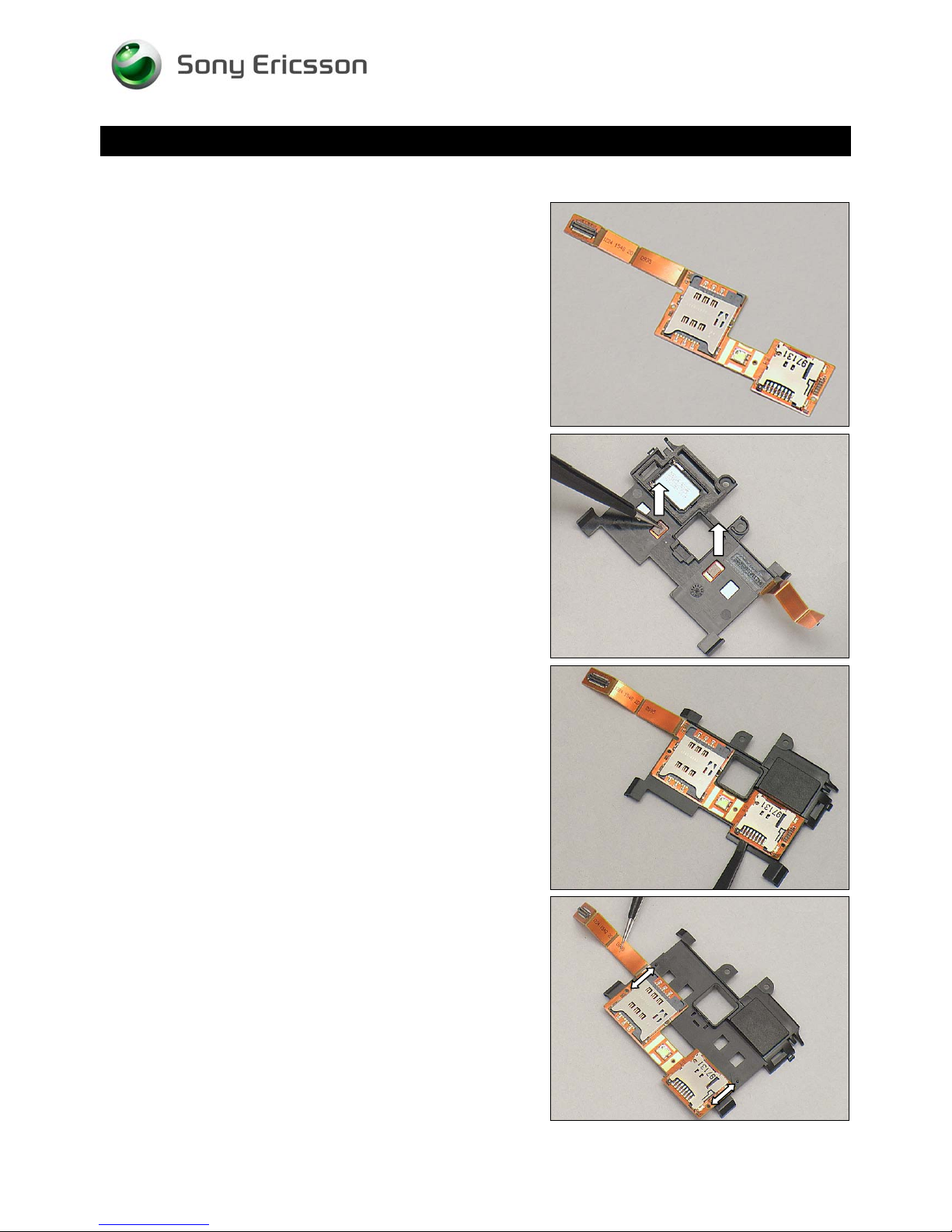
Replacement
4.36 SIM and MicroSD FPC
Follow the 3.1 – 3.4 Disassembly instructions!
Prepare a new SIM and MicroSD FPC.
Follow the 5.3 – 5.6 Reassembly instructions!
Working Instruction Repair Instruction Mechanical/
REMOVAL
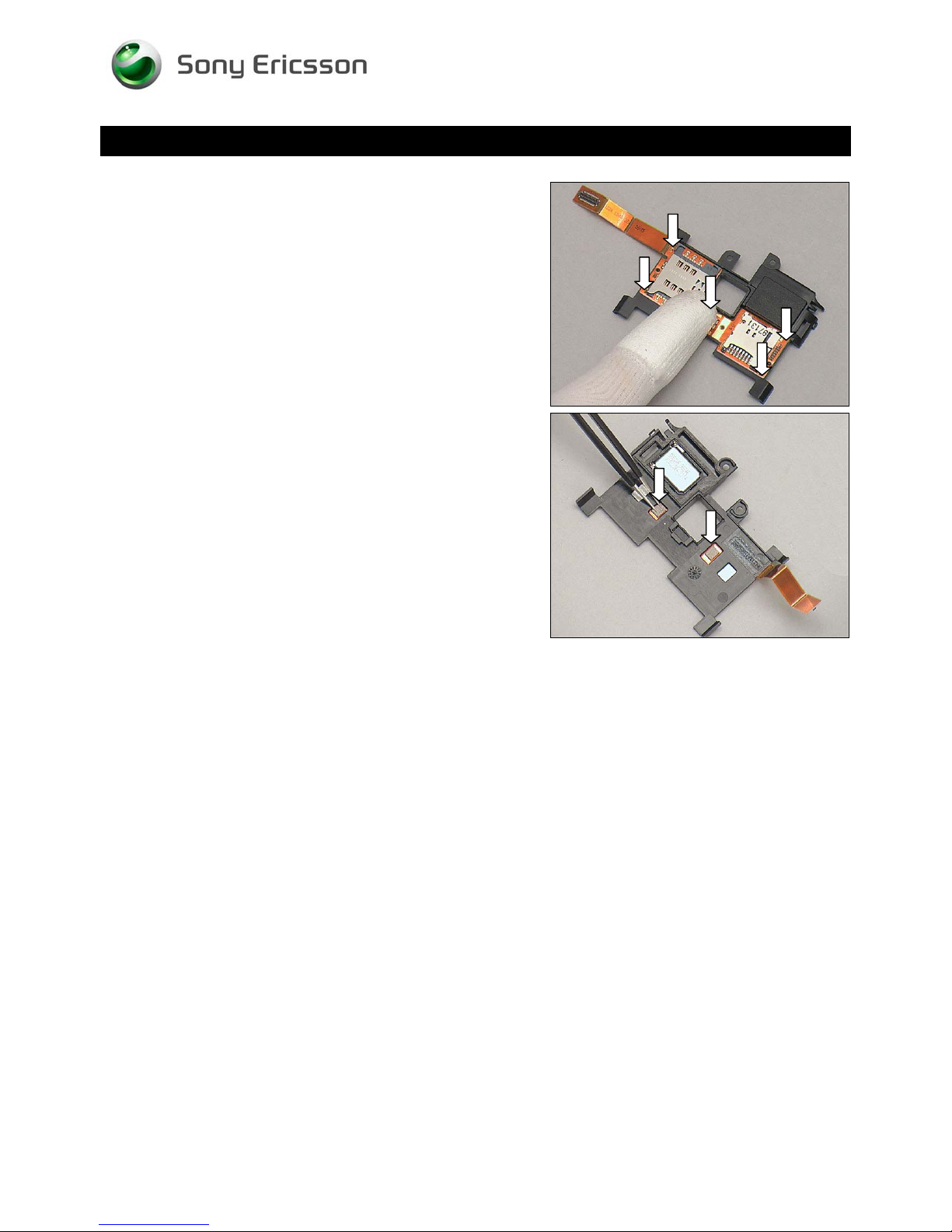
Remove the two Conductive Gaskets.
Detach and remove the SIM and MicroSD FPC gently.
INSTALLATION
Put a new SIM and MicroSD FPC and align it with the two
guiding poles of the Non-Celler Antenna Speaker Box.
1230-2324 Rev 6
Sony Ericsson Mobile Communications AB – Company Internal
70(81)
Page 71
Working Instruction Repair Instruction Mechanical/
Replacement: SIM and MicroSD FPC
Press to secure its attachment.
Put the two new Conductive Gaskets onto the Unit.
1230-2324 Rev 6
Sony Ericsson Mobile Communications AB – Company Internal
71(81)
Page 72
Working Instruction Repair Instruction Mechanical/
Replacement
4.37 Board Swap—Replace
Swap Board
Follow the 3.1 – 3.5 Disassembly instructions!
Follow the 4.9 Removal instructions!
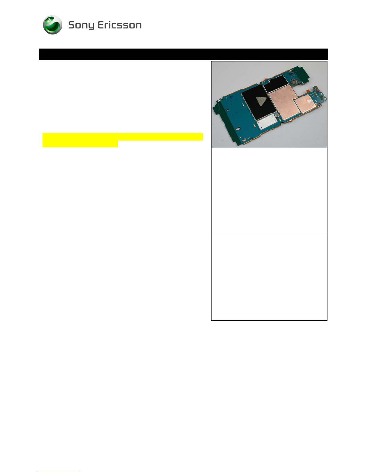
Prepare a new swap board.
Follow the 4.9 Installation instructions!
Follow the 5.2 - 5.2 Reassembly instructions!
NOTE: Startup the unit to initialize settings, before perform
Customize Phone in Emma
4.38 Board Swap – Change
Label
Change Label
Follow the instructions in the Generic Repair Manual –
Build swap for change of label.
4.39 Board Swap – Customize
Software
Customization of software
Follow the instructions in the Generic Repair Manual –
Build swap for customization of the software
1230-2324 Rev 6
Sony Ericsson Mobile Communications AB – Company Internal
72(81)
Page 73
5 Reassembly
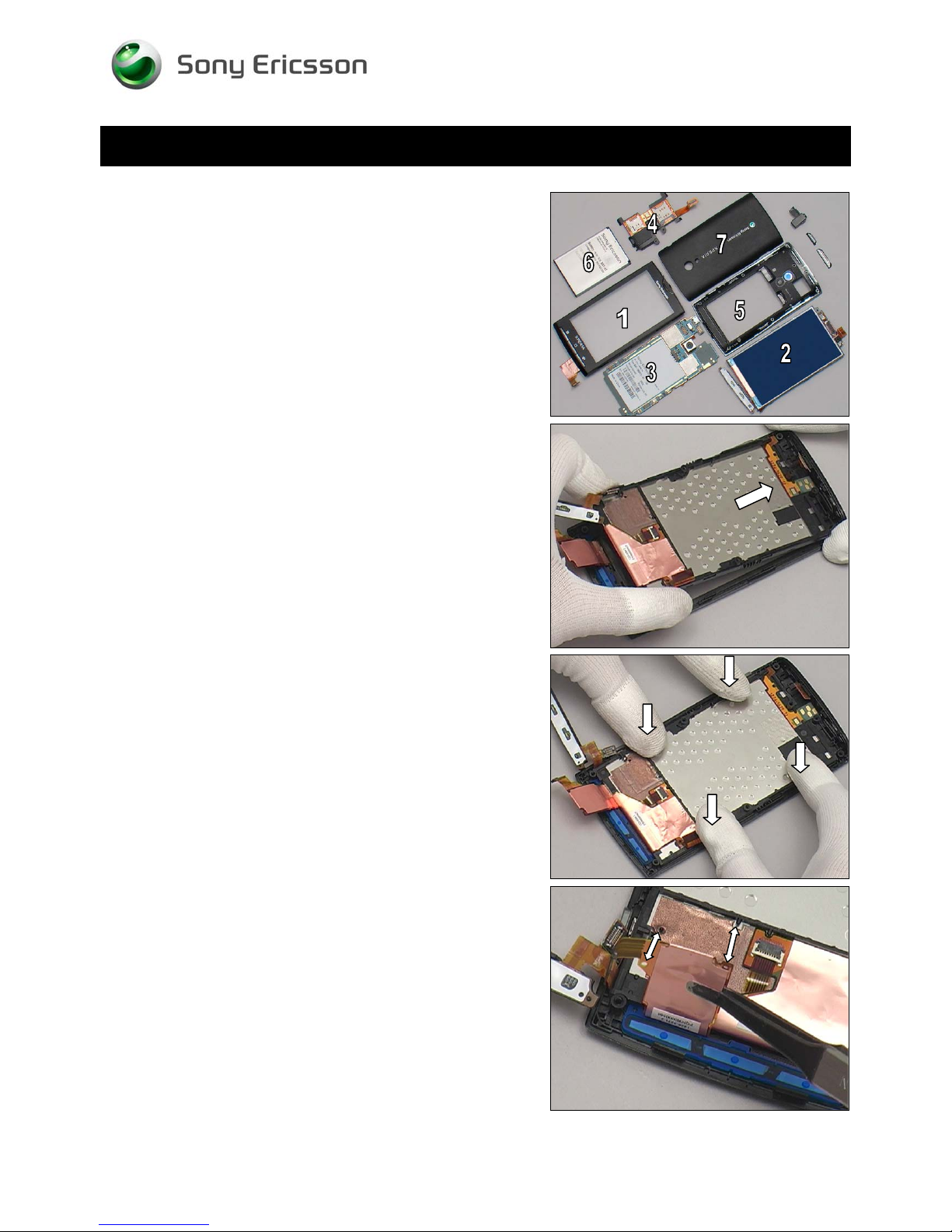
The reassembly is done in the following order:
1. Front Cover Assy
2. Frame Sub Assembly
3. Main PBA
4. Non-Celler Antenna Speaker Box
5. Rear Cover Assy
6. Battery
7. Battery Cover
Working Instruction Repair Instruction Mechanical/
5.1 Front Cover Assy &
Frame Sub Assembly
Place Frame Sub Assembly at approximately 30o onto the
Front Cover Assy.
Press the Frame Sub Assembly to snap it.
Attach the FPC aligned with the two guiding poles.
1230-2324 Rev 6
Sony Ericsson Mobile Communications AB – Company Internal
73(81)
Page 74
Reassembly
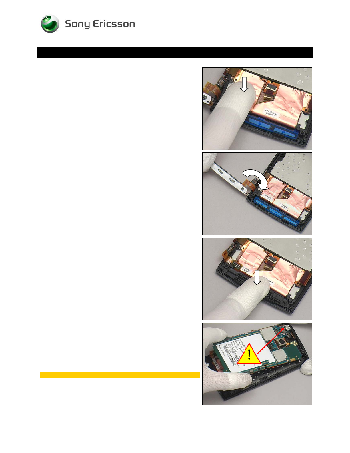
Press to secure its attachment.
Working Instruction Repair Instruction Mechanical/
Lift and gently turn over the Main Key Unit into its cavity.
Press the Main Key Unit to snap.
5.2 Main PBA
Place the Main PBA at approximately 30o.
Insert the Micro USB connector first!
1230-2324 Rev 6
Sony Ericsson Mobile Communications AB – Company Internal
74(81)
Page 75
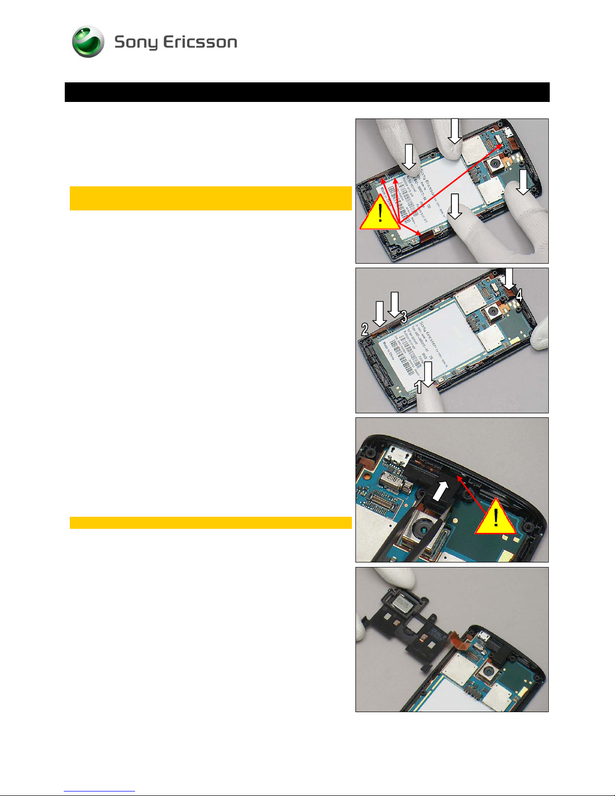
Working Instruction Repair Instruction Mechanical/
Reassembly
Press to snap the Unit.
Make sure all the BtB connectors are above the Main
PBA before press!
Snap the four BtB connectors as indicated
5.3 Non-Celler Antenna
Speaker Box
Put the Audio Jack Unit in place.
Make sure the Audio Jack head is inserted into the hole!
Put the Non-Celler Antenna Speaker Box in place.
1230-2324 Rev 6
Sony Ericsson Mobile Communications AB – Company Internal
75(81)
Page 76
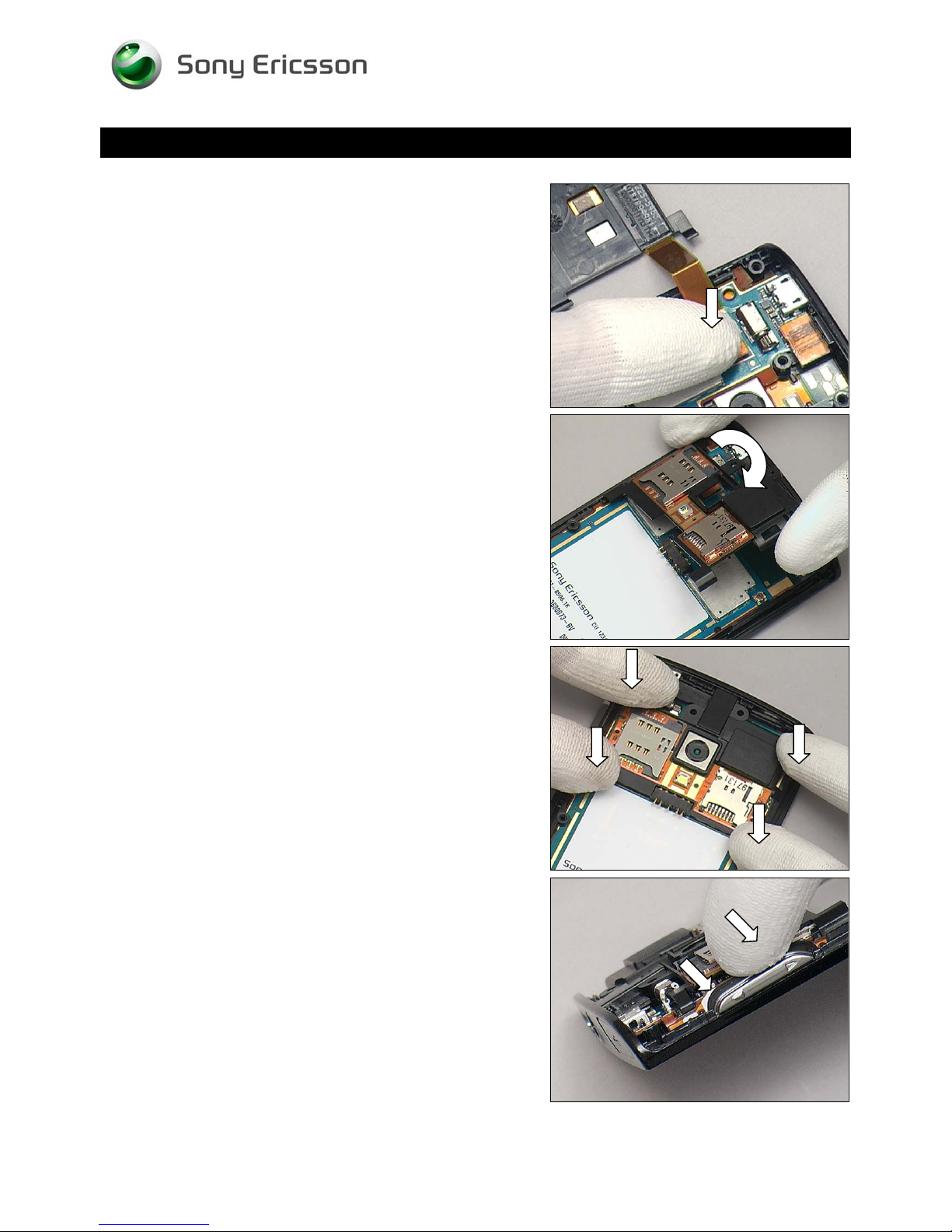
Reassembly
Press to snap the BtB connector by fingers.
Working Instruction Repair Instruction Mechanical/
Turn over the Non-Celler Antenna Speaker Box.
Press the four hooks to snap.
Put the Key Volume into its cavity.
1230-2324 Rev 6
Sony Ericsson Mobile Communications AB – Company Internal
76(81)
Page 77
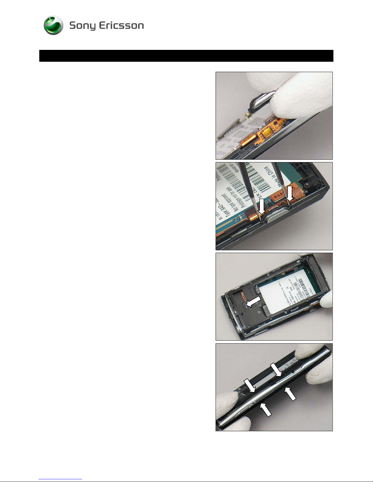
Reassembly
Put the Key Camera in place.
Working Instruction Repair Instruction Mechanical/
Fix the Key Camera by using a pair of tweezers.
5.4 Rear Cover Assy
Put the Rear Cover Assy in place.
Press to snap the four hooks in the direction of the arrows.
1230-2324 Rev 6
Sony Ericsson Mobile Communications AB – Company Internal
77(81)
Page 78
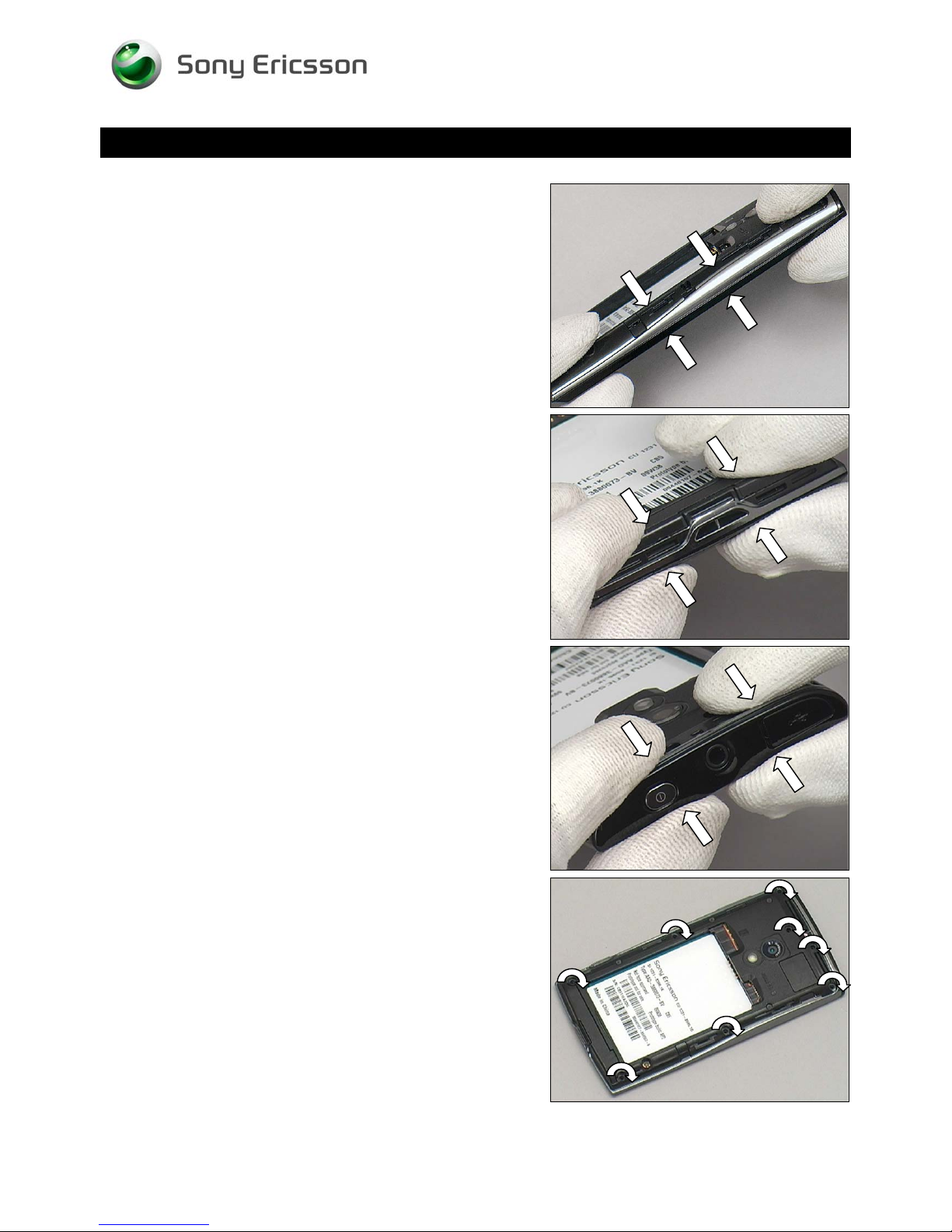
Reassembly
Press to snap the three hooks on the opposite side.
Working Instruction Repair Instruction Mechanical/
Press to snap the four hooks on the bottom side.
Press to snap the two hooks on the top side
Apply 20 Ncm torque when tightening eight Screw Other
Len:4.5 Diam:1.7 with T6.
1230-2324 Rev 6
Sony Ericsson Mobile Communications AB – Company Internal
78(81)
Page 79
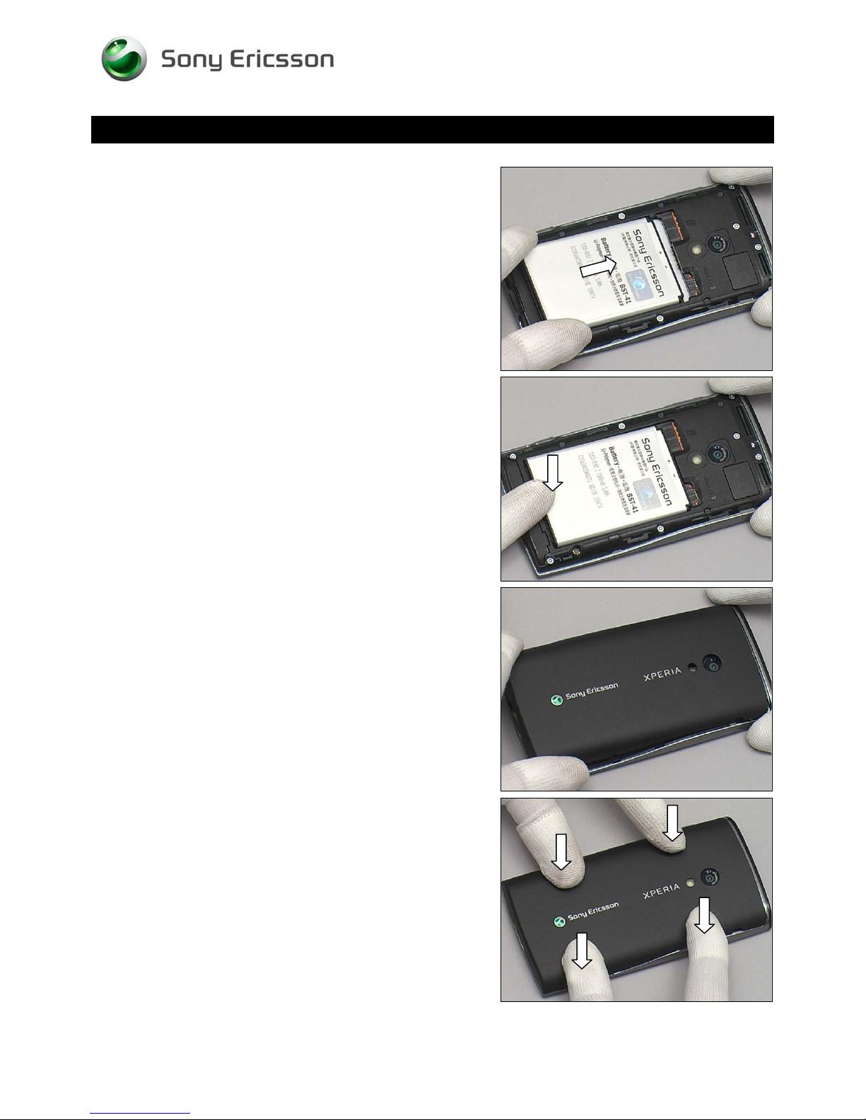
Reassembly
5.5 Battery
Put the Battery in place.
Working Instruction Repair Instruction Mechanical/
Press the Battery into its cavity.
5.6 Battery Cover
Put the Battery Cover in place.
Press to snap it.
1230-2324 Rev 6
Sony Ericsson Mobile Communications AB – Company Internal
79(81)
Page 80

Working Instruction Repair Instruction Mechanical/
6 Country of origin Barcodes for
Brazil/VIVO Labels
Below is a link to a list of countries of origin. If you are printing a Brazil or VIVO label, scan the barcode
corresponding to the correct country of origin for the “Fabricado” field.
1230-2324 Rev 6
Sony Ericsson Mobile Communications AB – Company Internal
80(81)
Page 81
Working Instruction Repair Instruction Mechanical/
7 Revision History
Rev. Date Changes / Comments
1 2010-Mar-11 Initial release
2 2010-05-10 Add Board Swap Chapter
3 2010-05-10 Update one photo one page8
4 2010-07-16 Update one sequence on page 20.
5 2010-07-29 Add chapter 6 about Brazil/VIVO label content
6 2010-09-16 Add info in chapter 4.37, for startup of unit
1230-2324 Rev 6
Sony Ericsson Mobile Communications AB – Company Internal
81(81)
 Loading...