

Page 1

Working Instruction, Mechanical
Working Instruction, Mechanical
Applicable for P1i and P1c
CONTENTS
1 Introduction .............................................................................. 3
1.1 Equipment.................................................................................4
1.2 General cautions ...................................................................... 5
1.3 Adhesives .................................................................................5
1.4 Recurrent Repair Actions ........................................................ 5
2 Disassembly ............................................................................. 6
2.1 Overview ...................................................................................6
3 Replacements......................................................................... 19
3.1 Keyboard support ..................................................................20
3.2 BtB flex....................................................................................20
3.3 Keyboard flex..........................................................................20
3.4 Keyboard.................................................................................20
3.5 Front ................................................................................. 20
3.6 Frame .................................................................................20
3.7 LCD .................................................................................20
3.8 Antenna lid..............................................................................20
3.9 Antenna flex............................................................................21
3.10 System connector .................................................................. 22
3.11 Ear speaker holder ................................................................. 23
3.12 Microphone grommet.............................................................24
3.13 LCD gasket (small) ................................................................. 25
3.14 Dust gasket (system connector)...........................................26
3.15 Vibrator.................................................................................... 27
3.16 Liquid intrusion indicator ...................................................... 28
3.17 Light guide ..............................................................................29
3.18 Camera ....................................................................................30
3.19 Shielding box..........................................................................32
3.20 Shielding box (CIF camera) ................................................... 34
3.21 Camera module (CIF) ............................................................. 36
3/000 21-1/FEA 209 544/126 A
Company Internal
© Sony Ericsson Mobile Communications AB
2.1.1 Battery lid and Battery ........................................................... 7
2.1.2 Antenna lid ............................................................................ 8
2.1.3 Front....................................................................................10
2.1.4 Keyboard and keyboard support .........................................13
2.1.5 Keyboard flex ......................................................................15
2.1.6 LCD ..................................................................................... 16
2.1.7 PCBA ..................................................................................17
Approved according to FEA matrix doc number
Page 2

Working Instruction, Mechanical
3.22 Flash flex.................................................................................38
3.23 Ear speaker ............................................................................. 41
3.24 Acoustic box...........................................................................43
3.25 Back key..................................................................................45
3.26 Operator key ........................................................................... 46
3.27 Camera key ............................................................................. 47
3.28 On/Off key ...............................................................................48
3.29 Touch Panel with Frame ........................................................ 49
3.30 Co brand plate ........................................................................ 52
3.31 Co brand label ........................................................................53
3.32 External antenna cap ............................................................. 54
3.33 Sub Pcba .................................................................................55
3.34 Label ......................................................................................56
4 Reassembly ............................................................................ 58
4.1 Overview .................................................................................58
4.1.1 Torque overview..................................................................59
4.1.2 PCBA and Frame ................................................................ 60
4.1.3 LCD ..................................................................................... 62
4.1.4 Keyboard flex ......................................................................63
4.1.5 Front....................................................................................65
4.1.6 Antenna Lid ......................................................................... 66
4.1.7 Battery lid and Battery ......................................................... 67
5 Revision history ..................................................................... 68
3/000 21-1/FEA 209 544/126 A
© Sony Ericsson Mobile Communications AB
2(68)
Page 3
Working Instruction, Mechanical
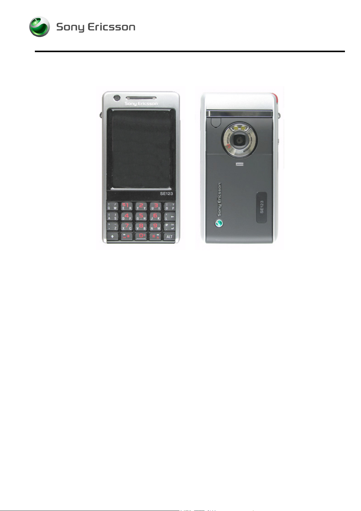
1 Introduction
P1i
3/000 21-1/FEA 209 544/126 A
Company Internal
© Sony Ericsson Mobile Communications AB
Approved according to FEA matrix doc number
Page 4
Working Instruction, Mechanical
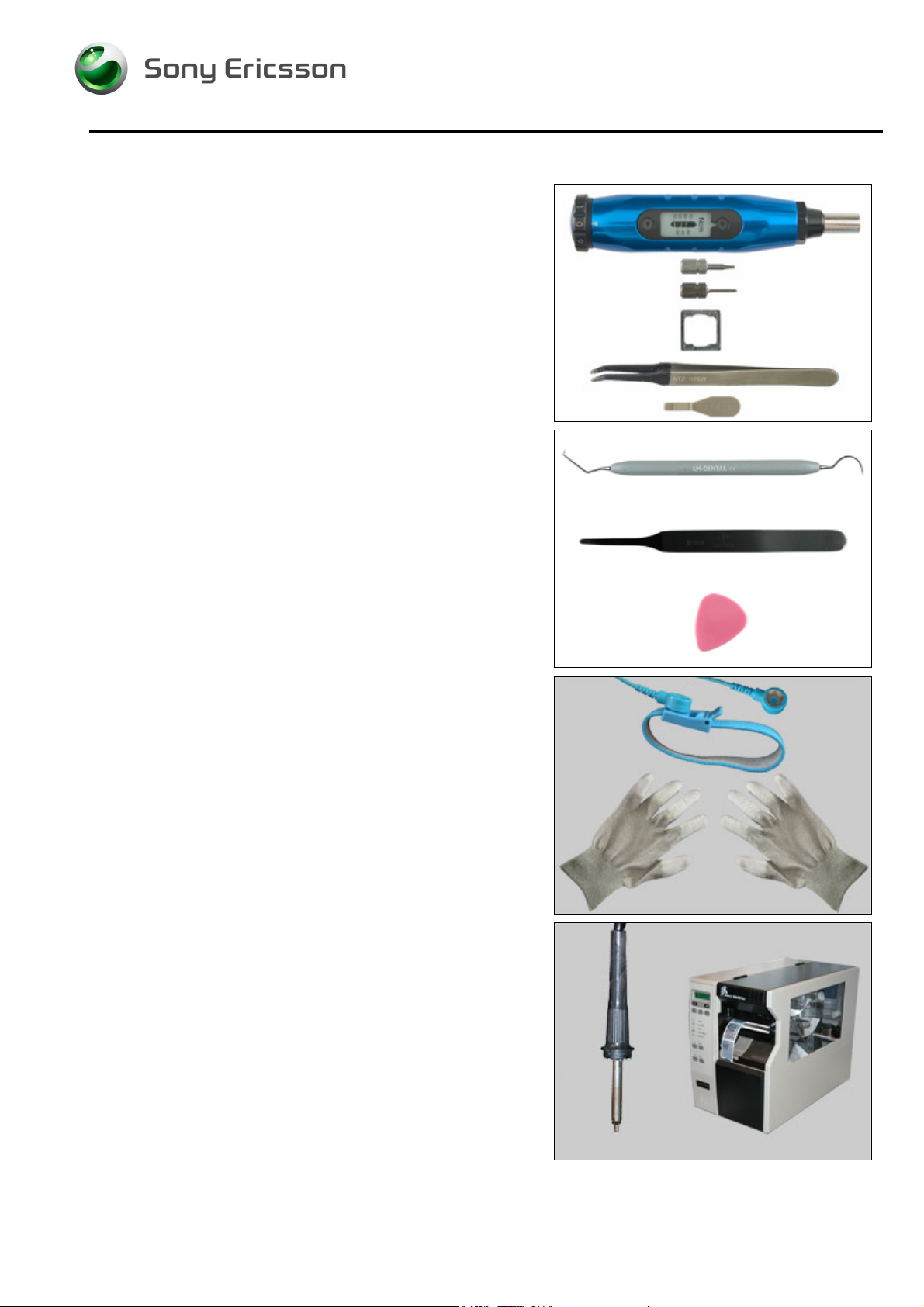
1.1 Equipment
SPECIAL TOOLS
Requirements (no new tools):
• NTZ 112 459 Torque screwdriver (or equivalent)
• NTZ 112 288 Torx bit no. 6
• NTZ 112 1052 JCIS bit
• NTZ 112 583 Camera removal tool
• NTZ 112 521 Flex film assembly tool
• NTZ 112 302/2 Front opening tool (Black or beige)
STANDARD TOOLS
The following tools have to be locally purchased:
• Dentist hook
• Blunt pair of tweezers
• NTZ 112 590 Plectrum
ESD EQUIPMENT
Protect the phone from ESD damages whenever it has
been opened by using:
• ESD-wristband
• ESD-gloves
LABEL EQUIPMENT
The following special equipment is required when replacing
or installing a new label:
• Hot air flow solder station
• Zebra printer connected to computer
3/000 21-1/FEA 209 544/126 A
Company Internal
© Sony Ericsson Mobile Communications AB
Approved according to FEA matrix doc number
Page 5
d
Working Instruction, Mechanical
1.2 General cautions
The following cautions are considered to be generic for all phone models and will not be repeated in
the Disassembly, Replacements and Reassembly sections:
WITCH OFF THE PHONE AND REMOVE SIM CARD AND MEMORY STICK BEFORE STARTING
• S
DISASSEMBLING THE PHONE!
• K
EEP ALL CONTACT SURFACES CLEAN!
E CAREFUL WHEN USING TOOLS LIKE THE DENTIST HOOK, TWEEZERS, OPENING TOOLS, PLECTRUMK
• B
ETC. TO AVOID SCRATCHES OR DAMAGES TO THE EXTERIOR AND INTERIOR PARTS OF THE PHONE!
• B
E CAREFUL NOT TO DAMAGE ANY CONTACT SPRINGS!
EMEMBER TO REMOVE THE PROTECTION FOILS ON NEW PARTS SUCH AS THE FRONT COVER AND LCD!
• R
EVER TOUCH THE DISPLAY GLASS!
• N
SE AIR BLOW EQUIPMENT TO KEEP THE FRONT WINDOW AND DISPLAY MODULE DUST FREE!
• U
Remove the
SIM car
!
1.3 Adhesives
Use a dentist hook and/or the tweezers to remove old adhesives.
Clean the surface with isopropyl alcohol before attaching new adhesives.
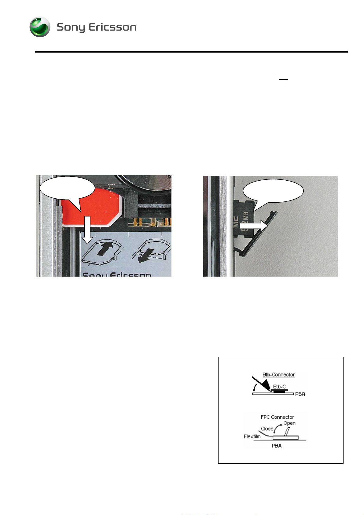
1.4 Recurrent Repair Actions
Remove the
memory stick!
How to open a board-to-board connector with the front
opening tool.
How to open and close a FPC connector – Be very careful
with the hinge mechanism.
3/000 21-1/FEA 209 544/126 A
Company Internal
© Sony Ericsson Mobile Communications AB
Approved according to FEA matrix doc number
Page 6
(
Working Instruction, Mechanical
2 Disassembly
When you are going to replace a part being listed in Replacements, the instruction of that section
usually begins by directing you to this Disassembly section with a specification of the instructions you
have to carry out in order to disassemble the phone as far as needed before returning to
Replacements for the actual replacement.
REPLACEMENTS
Start
Contents
page
DISASSEMBLY
REASSEMBLY
Done
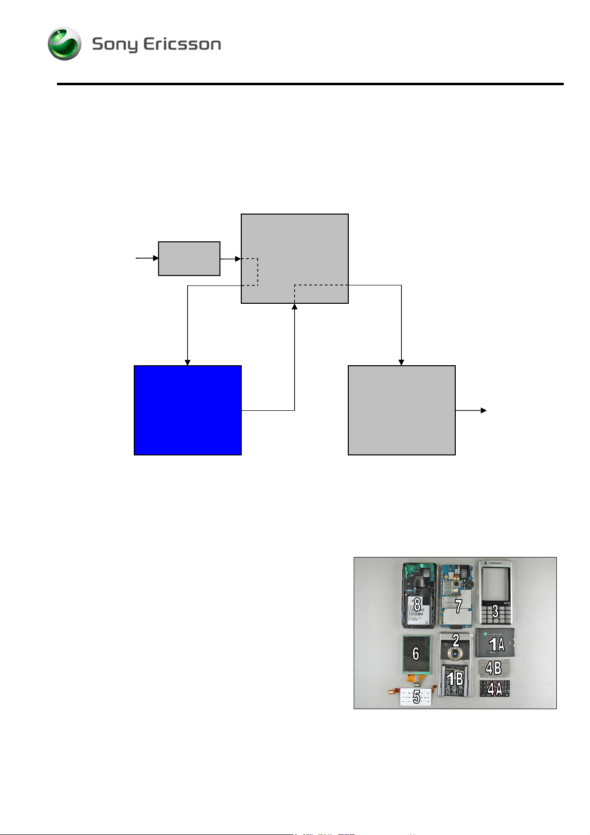
2.1 Overview
The disassembly is done in the following sequence:
1. Battery Lid – A, and Battery - B
2. Antenna lid
3. Front
4. Keyboard A and Keyboard support, B
5. Keyboard flex
6. LCD
7. PCBA
8. Frame
3/000 21-1/FEA 209 544/126 A
Company Internal
with sub PCBA)
© Sony Ericsson Mobile Communications AB
Approved according to FEA matrix doc number
Page 7
Working Instruction, Mechanical
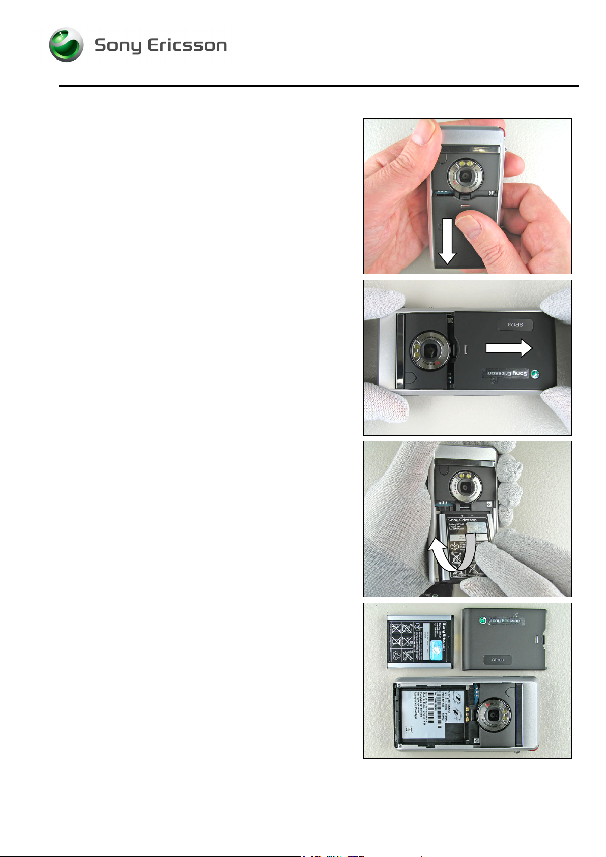
2.1.1 Battery lid and Battery
THERE IS NO NEED FOR ESD-GLOVES DURING THIS OPERATION!
Press with your thumb on the battery lid until you get a gap.
Remove the battery lid completely.
Start to remove the battery from the phone with your
fingers. Lift up the battery in the top end to unleash it.
If not released, turning the phone around at the same time
will make it become released.
Remove the battery completely from the phone with your
fingers.
3/000 21-1/FEA 209 544/126 A
Company Internal
© Sony Ericsson Mobile Communications AB
Approved according to FEA matrix doc number
Page 8
Working Instruction, Mechanical
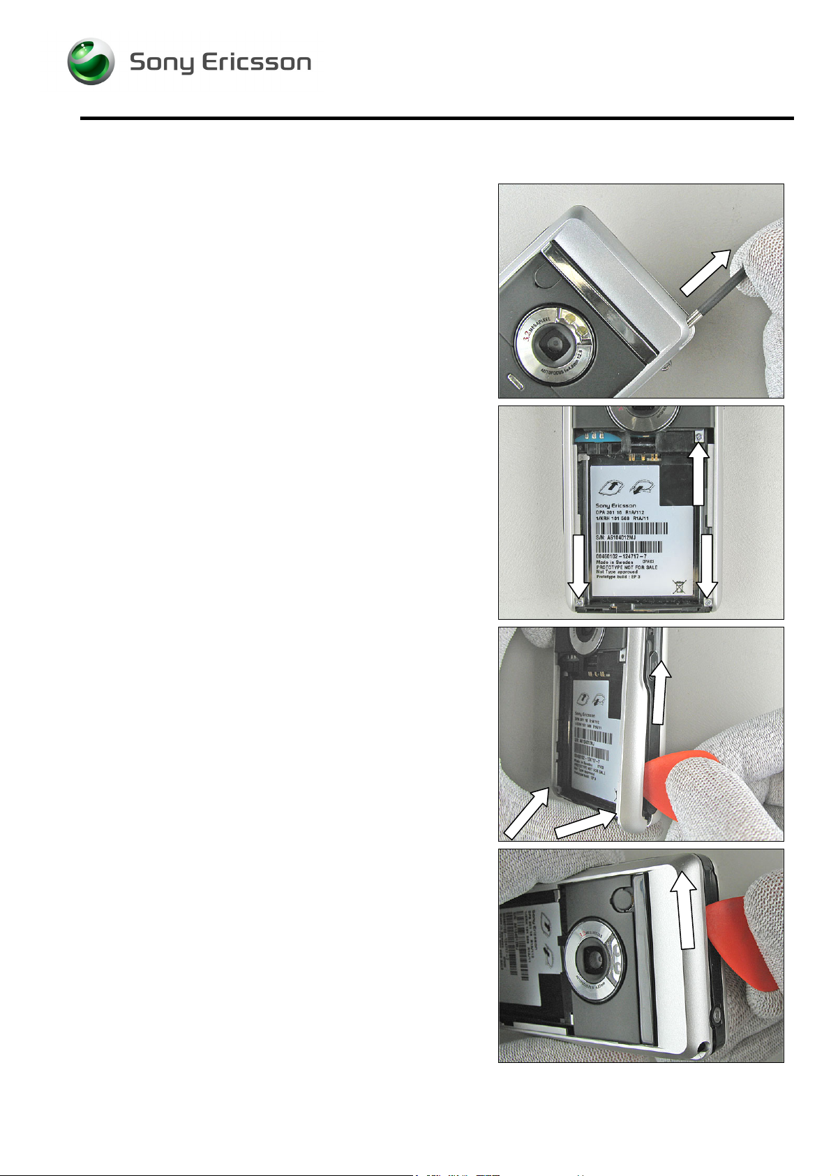
2.1.2 Antenna lid
Remove the Stylus pen.
Remove the 3 screws under the battery cover by using the
Use (NTZ 112 1052 JCIS bit) tool.
Carefully insert the plectrum (NTZ 112 590) under the
antenna lid and bend until they become loose.
Start at the bottom corners and continue and work your
wayup on both sides until it becomes loose.
And finally (around the corner) until the antenna lid is loose
on the top side.
3/000 21-1/FEA 209 544/126 A
Company Internal
© Sony Ericsson Mobile Communications AB
Approved according to FEA matrix doc number
Page 9
Working Instruction, Mechanical
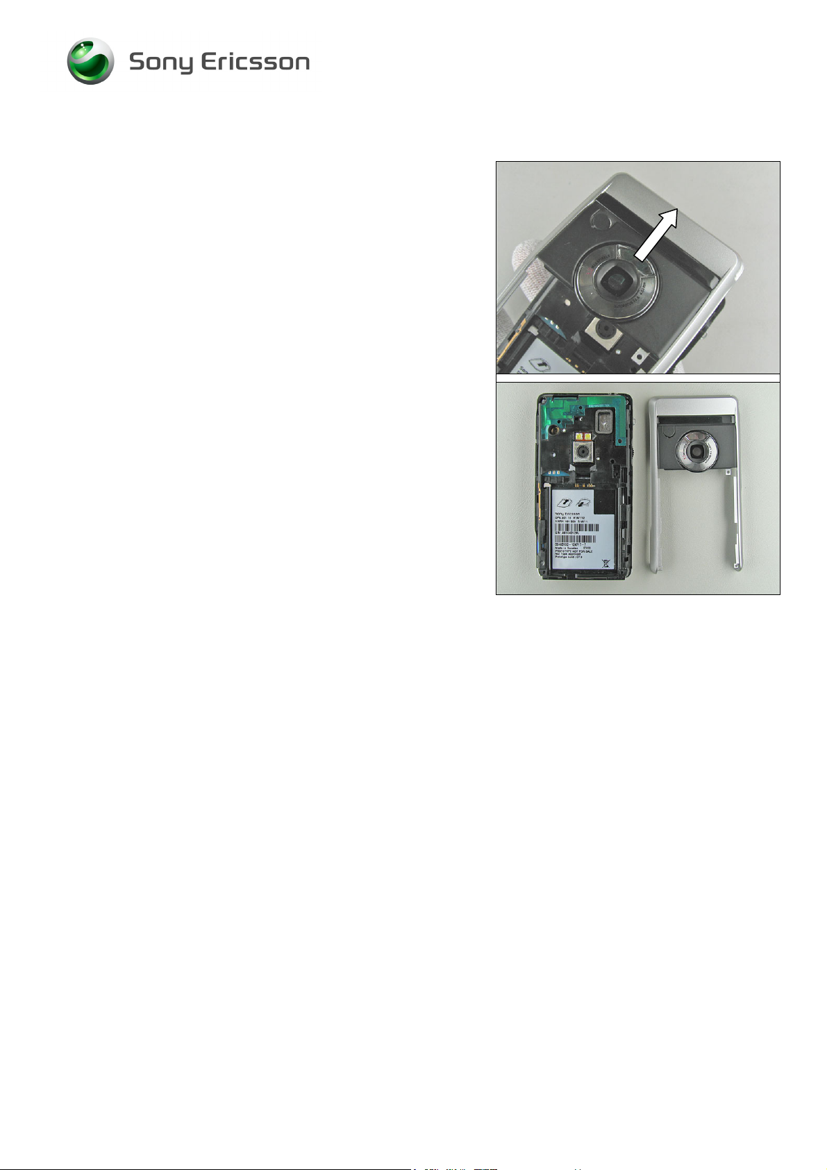
Disassembly Instruction continued
Gently lift off the antenna.
Disassembled antenna lid.
3/000 21-1/FEA 209 544/126 A
© Sony Ericsson Mobile Communications AB
9(68)
Page 10

Working Instruction, Mechanical
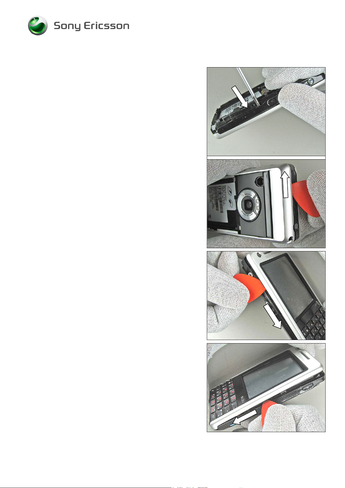
2.1.3 Front
Remove the 2 screws by using the NTZ 112 288 (torx bit
no 6).
Gently fold the flexfilm to reach the right screw.
There are 3 latches that have to be released before the
front can be removed.
Insert a flat screwdriver in the gap on the front.
Carefully bend in the arrow direction until the latch loosens.
BE CAREFUL SO THE W-LAN ANTENNA DOSENT GET DAMAGED !
Insert the screwdriver in the gap on the right side and bend
carefully in the arrow direction until the latch loosens.
3/000 21-1/FEA 209 544/126 A
© Sony Ericsson Mobile Communications AB
10(68)
Page 11
Working Instruction, Mechanical
Disassembly Instruction continued
Insert the screwdriver in the gap on the left side and bend
carefully in the arrow direction until the latch loosens.
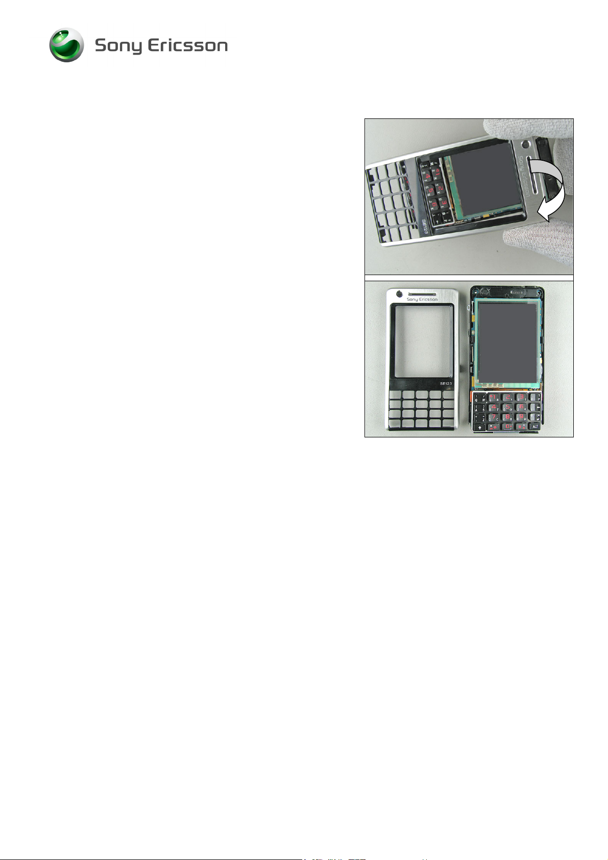
Insert the plectrum at the top of the front cover.
Continue to gently bend until the cover starts to become
loose from the frame.
Continue and move the plectrum up and along this side until
it becomes loose.
Continue with the other side and move the plectrum up and
along this side until it becomes loose.
3/000 21-1/FEA 209 544/126 A
© Sony Ericsson Mobile Communications AB
11(68)
Page 12
Working Instruction, Mechanical
Disassembly Instruction continued
Carefully bend the front cover upwards and forward until it
looses from the frame.
Disassembled Front cover.
3/000 21-1/FEA 209 544/126 A
© Sony Ericsson Mobile Communications AB
12(68)
Page 13
Working Instruction, Mechanical
2.1.4 Keyboard and keyboard support
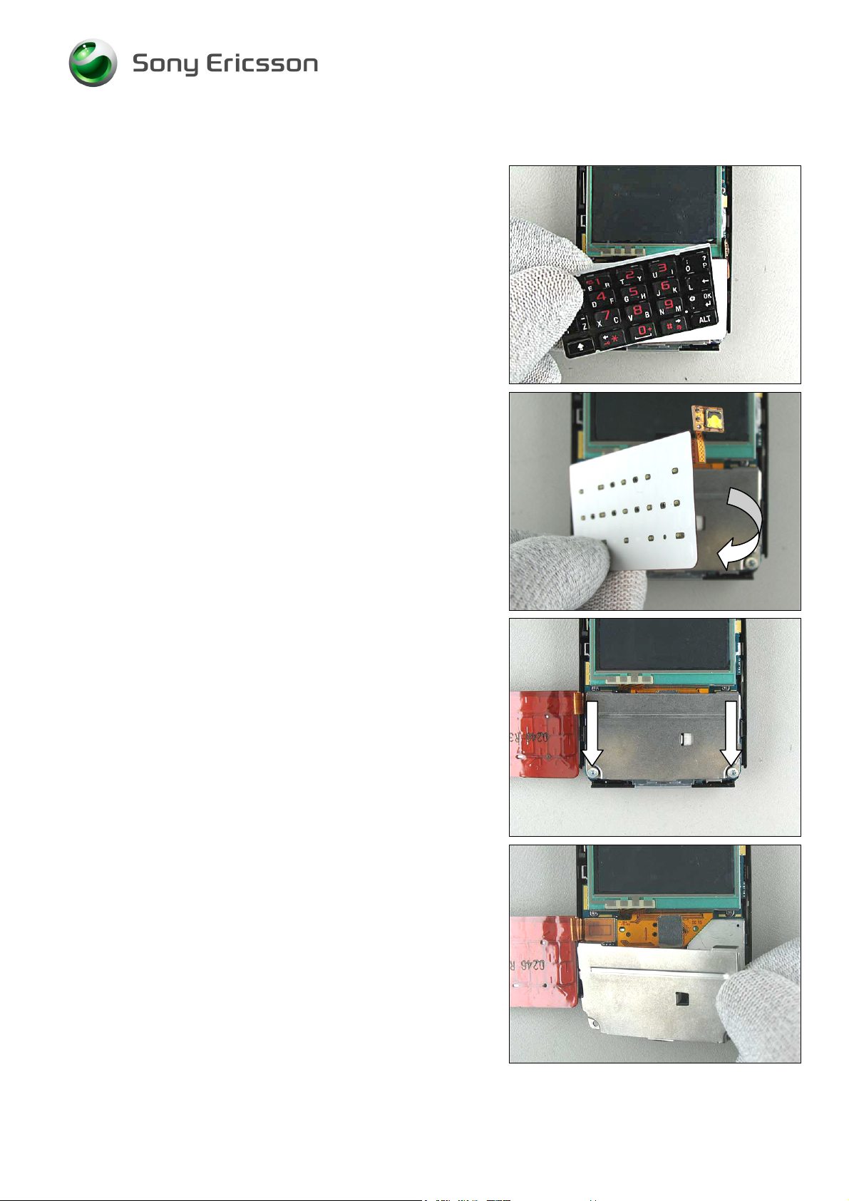
Remove the keyboard.
Fold the Keyboard flex.
Loosen the 2 screws.
Use (Use (NTZ 112 288 Torx 6 bit) tool.
Remove the Keyboard support.
3/000 21-1/FEA 209 544/126 A
© Sony Ericsson Mobile Communications AB
13(68)
Page 14
Working Instruction, Mechanical
Disassembly Instruction continued
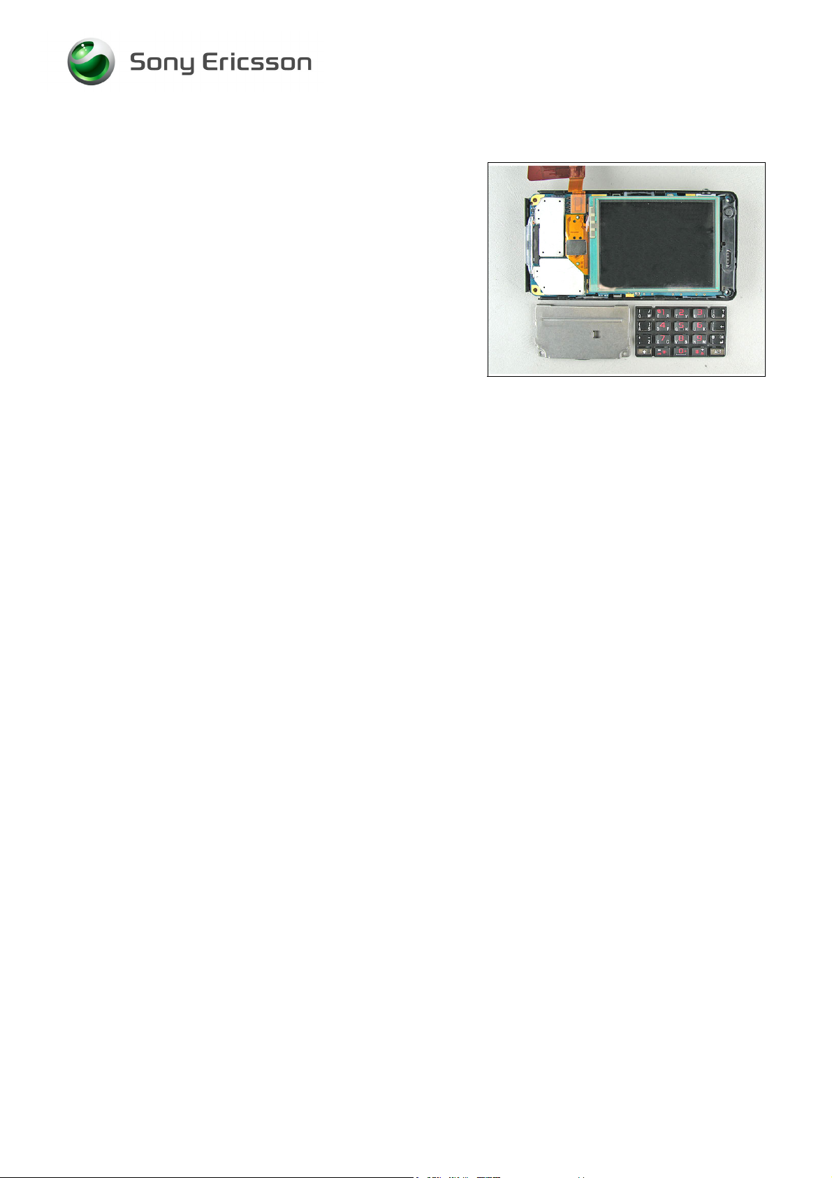
Keyboard and Keyboard support disassembled.
3/000 21-1/FEA 209 544/126 A
© Sony Ericsson Mobile Communications AB
14(68)
Page 15
Working Instruction, Mechanical
2.1.5 Keyboard flex
BE CAREFUL WITH THE FLEX FILM AND THE BOARD TO BOARD
CONNECTOR
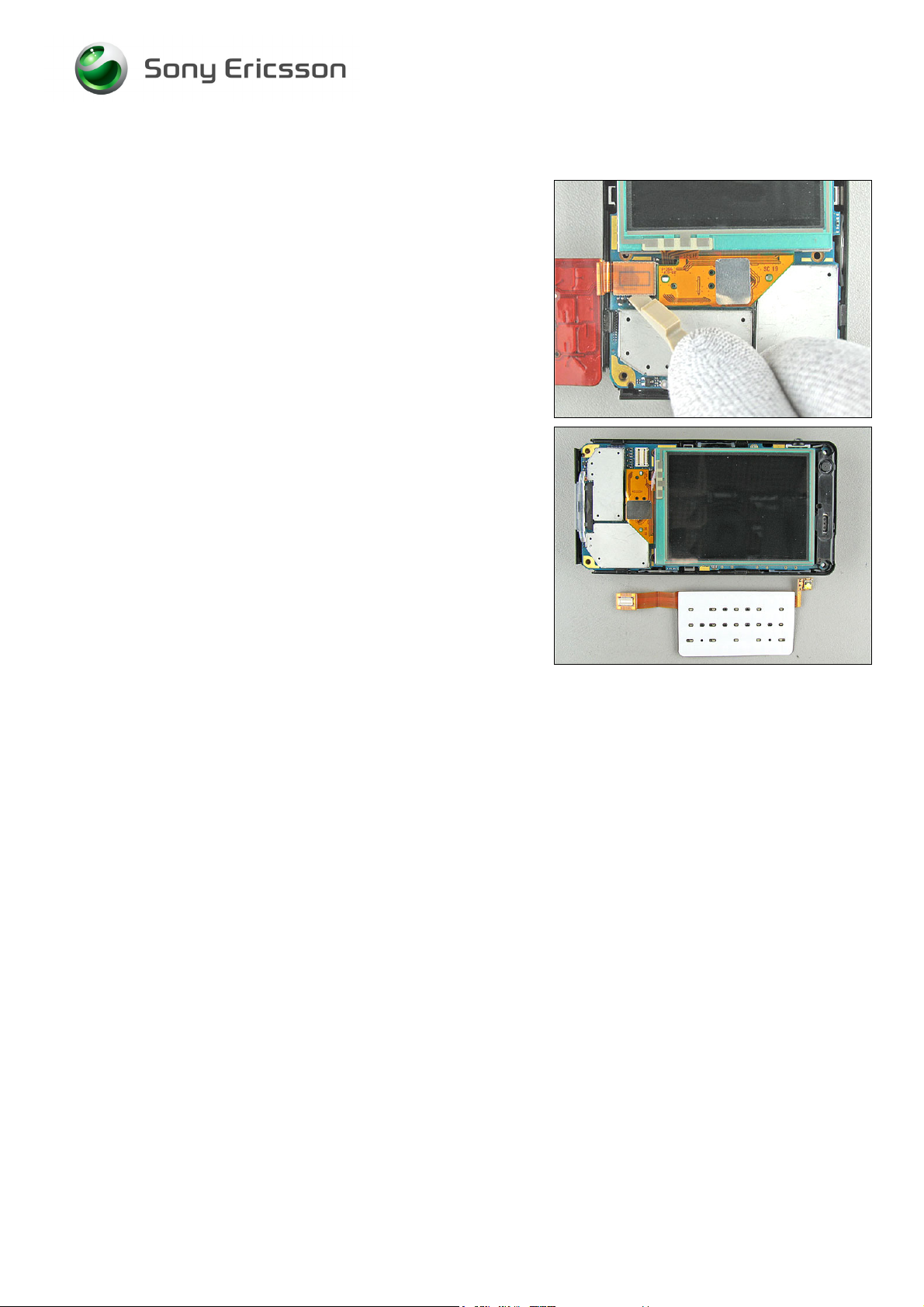
Disconnect the flex film board to board connector from the
PCBA with the front opening tool and remove the keyboard
flex.
!
Keyboard flex disassembled.
3/000 21-1/FEA 209 544/126 A
© Sony Ericsson Mobile Communications AB
15(68)
Page 16
Working Instruction, Mechanical
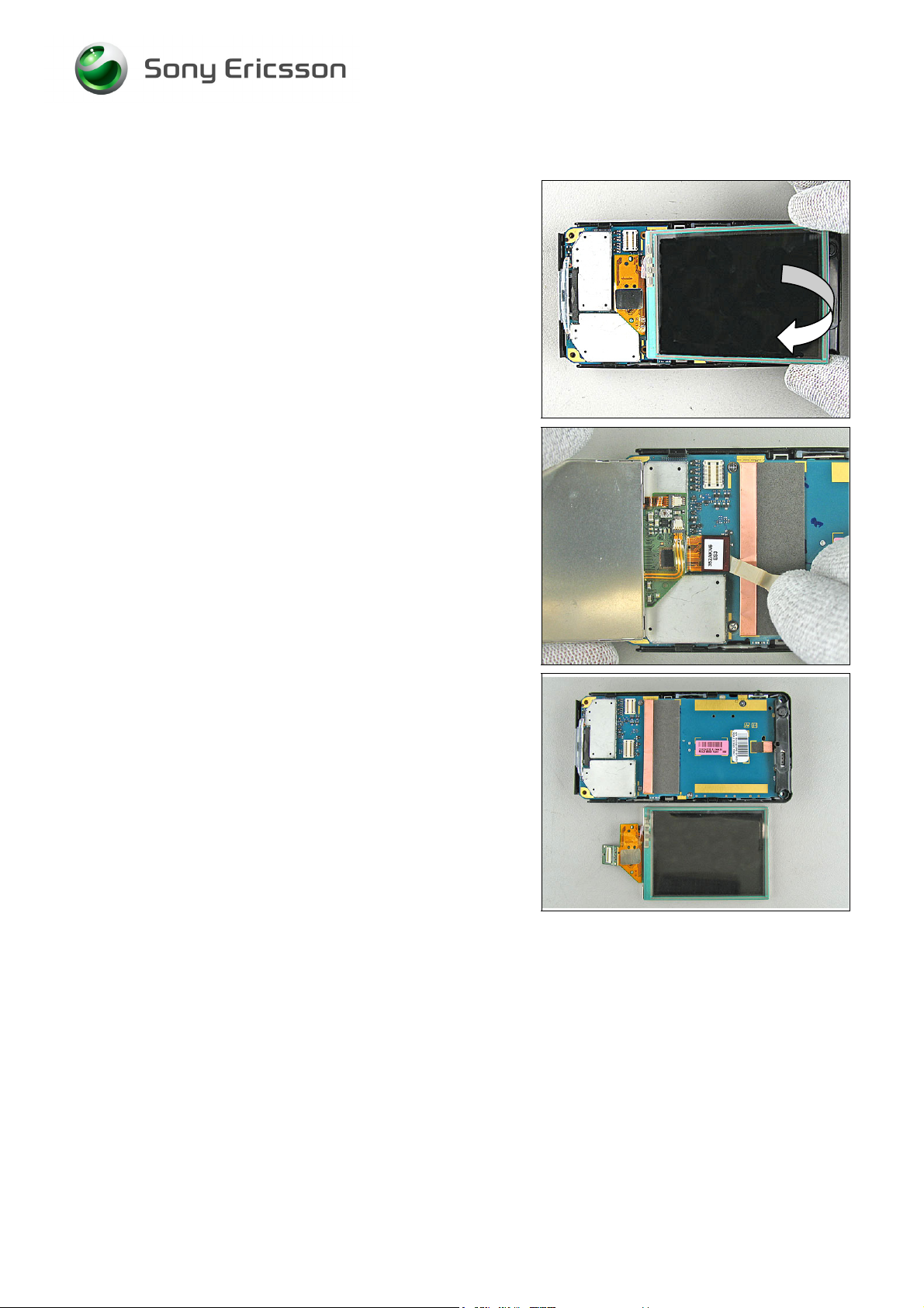
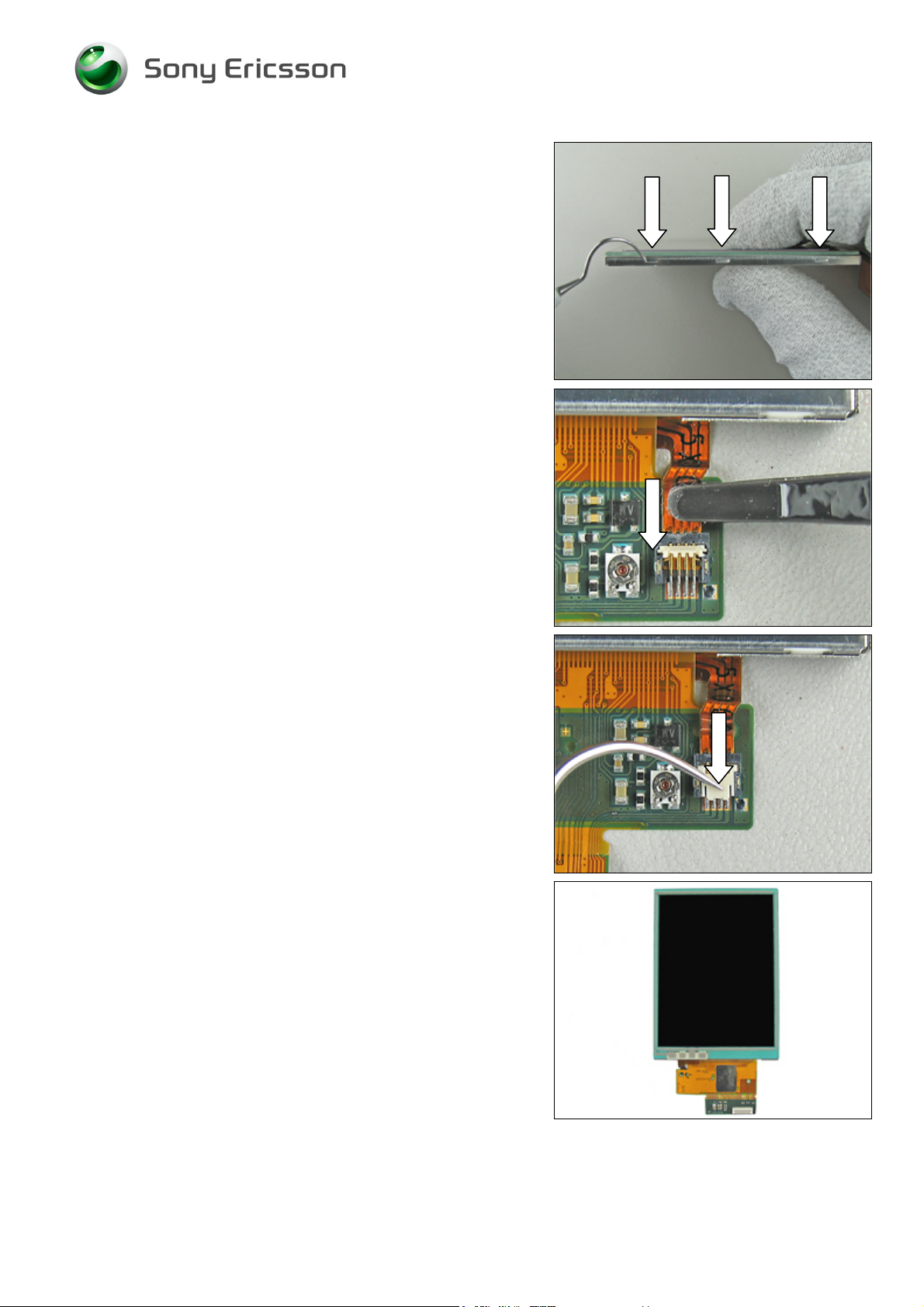
2.1.6 LCD
Fold the LCD forward.
BE CAREFUL WITH THE FLEX FILM AND THE BOARD TO BOARD
CONNECTOR
!
Disconnect the LCD flex film board to board connector
from the PCBA with the front opening tool.
LCD disassembled.
3/000 21-1/FEA 209 544/126 A
© Sony Ericsson Mobile Communications AB
16(68)
Page 17
Working Instruction, Mechanical
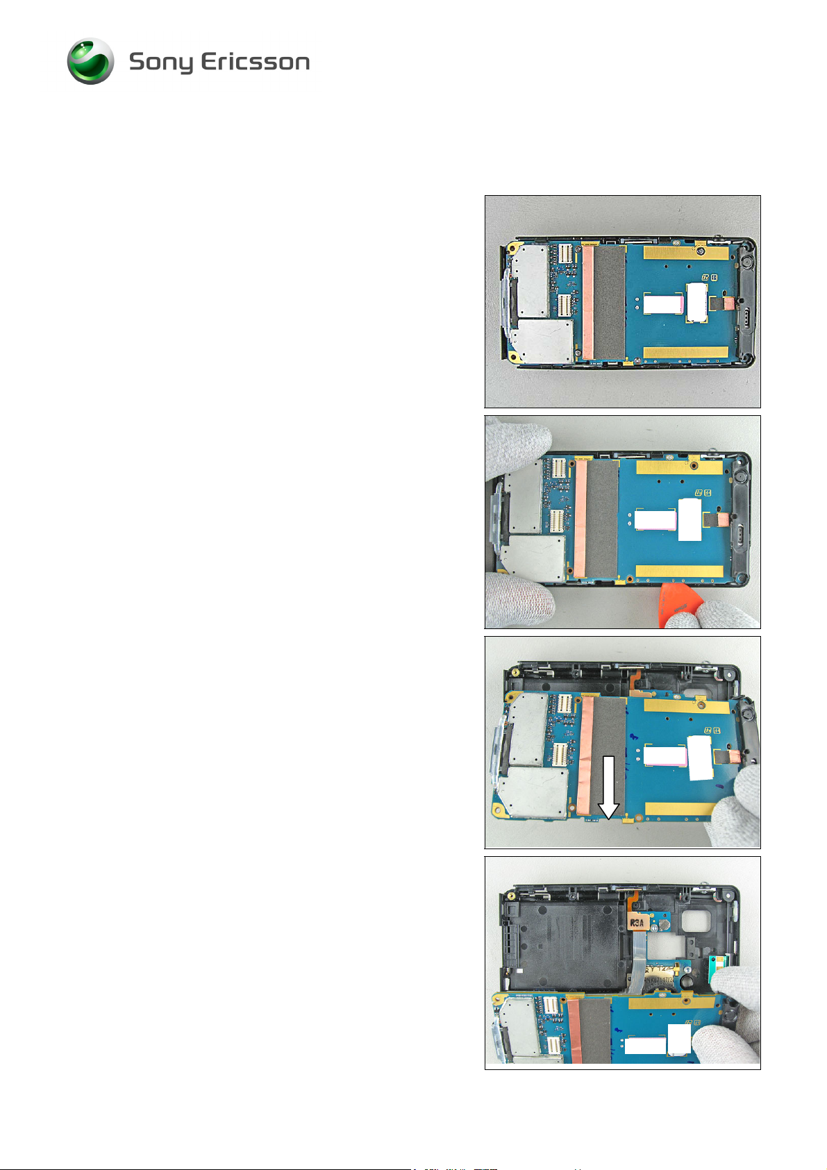
2.1.7 PCBA
Loosen the 5 screws.
Use (NTZ 112 1052 JCIS bit) tool.
Insert the plectrum and carefully bend until the PCBA
loosens from the frame.
.
Lift up the PCBA and remove it in the arrows direction
Hold the PCBA beside the frame.
3/000 21-1/FEA 209 544/126 A
© Sony Ericsson Mobile Communications AB
17(68)
Page 18
Working Instruction, Mechanical
Disassembly Instruction continued
BE CAREFUL WITH THE FLEX FILM AND THE BOARD TO BOARD
CONNECTOR
Disconnect the flex film board to board connector from the
frame with the front opening tool.
!
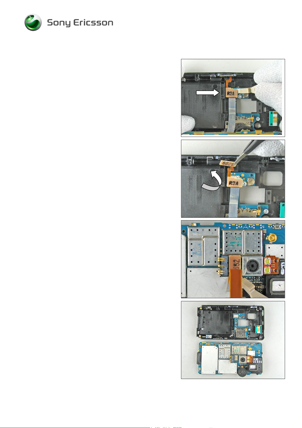
BE CAREFUL WITH THE FLEX FILM AND THE BOARD TO BOARD
CONNECTOR
!
Remove the flexfilm. Use a pair of tweezers.
BE CAREFUL WITH THE FLEX FILM AND THE BOARD TO BOARD
CONNECTOR ON THE PCBA
!
Disconnect the flex film board to board connector from the
PCBA with the front opening tool.
PCBA disassembled. The phone is now disassembled.
3/000 21-1/FEA 209 544/126 A
© Sony Ericsson Mobile Communications AB
18(68)
Page 19

Working Instruction, Mechanical
3 Replacements
Search for the part to be replaced on the Contents page and go to that instruction to be found in this
Replacements section.
The instruction usually begins by directing you to the Disassembly section with a specification of the
instructions you have to carry out in order to disassemble the phone as far as needed before the
actual replacement.
Go back to this Replacements section and carry out the instruction.
The instruction usually ends by directing you to the Reassembly section with a specification of the
instructions you have to carry out in order to reassemble the phone.
REPLACEMENTS
Start
Contents
page
DISASSEMBLY REASSEMBLY
Done
3/000 21-1/FEA 209 544/126 A
Company Internal
© Sony Ericsson Mobile Communications AB
Approved according to FEA matrix doc number
Page 20

Working Instruction, Mechanical
3.1 Keyboard support
Follow the 2.1.1 – 2.1.4 Disassembly instructions!
Prepare the new Keyboard support.
Follow the 4.1.3 - 4.1.6 Reassembly instructions!
3.2 BtB flex
Follow the 2.1.1 – 2.1.7 Disassembly instructions!
Prepare the BtB flex.
Follow the 4.1.1 – 4.1.6 Reassembly instructions!
3.3 Keyboard flex
Follow the 2.1.1 – 2.1.4 Disassembly instructions!
Prepare the new Keyboard flex.
Follow the 4.2.3 – 4.1.6 Reassembly instructions!
3.4 Keyboard
Follow the 2.1.1 – 2.1.4 Disassembly instructions!
Prepare the new Keyboard.
Follow the 4.1.3 – 4.2.6 Reassembly instructions!
3.5 Front
Follow the 2.1.1 – 2.1.3 Disassembly instructions!
Prepare the new Front.
Follow the 4.1.4 – 4.1.6 Reassembly instructions!
3.6 Frame
Follow the 2.1.1 – 2.1.7 Disassembly instructions!
Prepare the new Frame.
Follow the 4.1.1 – 4.1.6 Reassembly instructions!
3.7 LCD
Follow the 2.1.1 - 2.1.6 Disassembly instructions!
Prepare the new LCD.
Follow the 4.1.2 – 4.1.6 Reassembly instructions!
3.8 Antenna lid
Follow the 2.1.1 Disassembly instructions!
Prepare the new Antenna lid.
Follow the 4.1.1.2 Reassembly instructions!
3/000 21-1/FEA 209 544/126 A
Company Internal
© Sony Ericsson Mobile Communications AB
Approved according to FEA matrix doc number
Page 21
Working Instruction, Mechanical
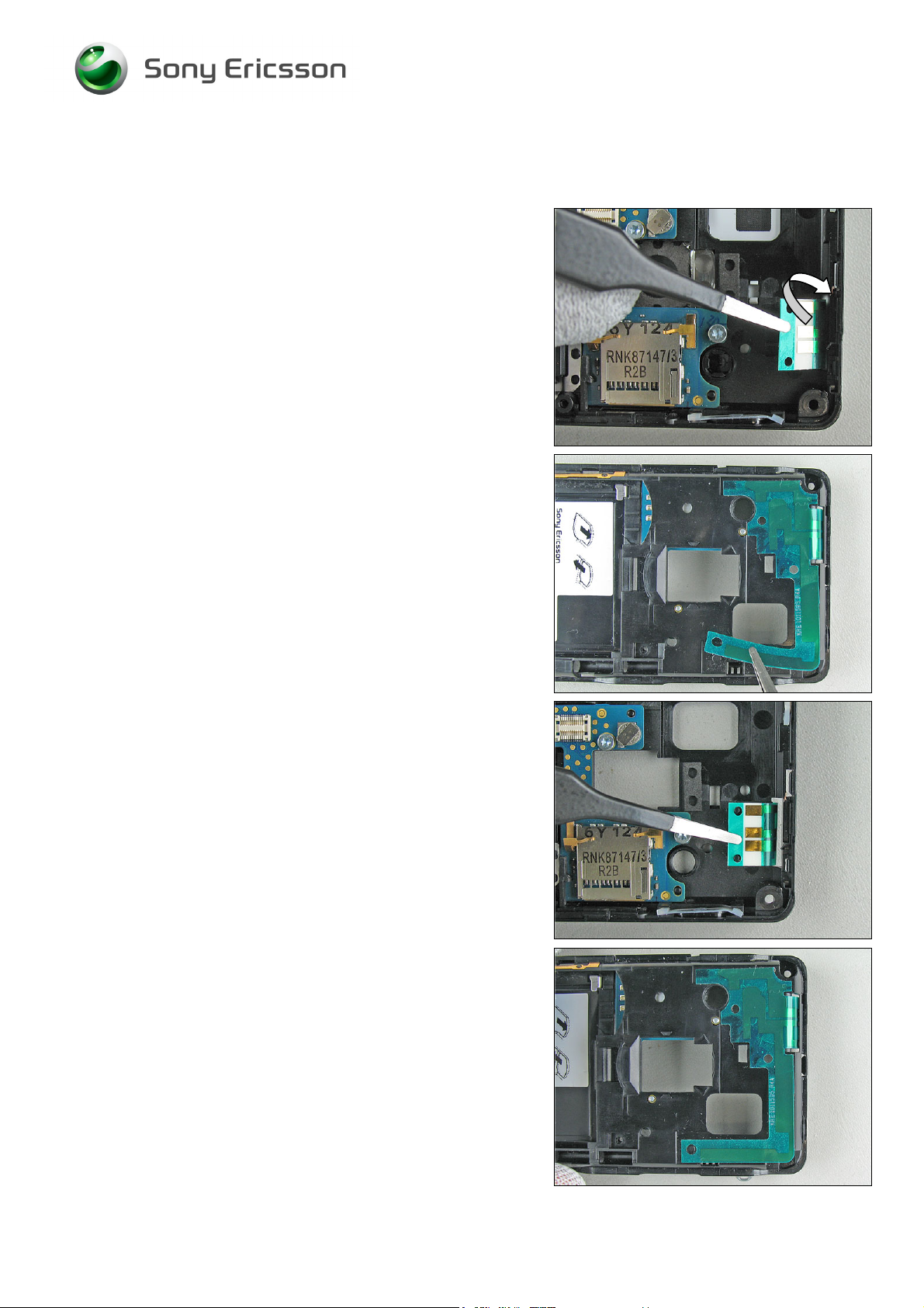
3.9 Antenna flex
REMOVAL
Follow the 2.1.1 – 2.1.7 Disassembly instructions!
Start to carefully bend up the Antenna flex with a blunt pair
of tweezers.
Turn the frame around.
Remove the old Antenna flex with a blunt pair of tweezers.
INSTALLATION
Fold down the Antenna flex over the guiding pins.
Press down the new Antenna flex onto the frame.
Follow the 4.2.4 – 4.2.6 Reassembly instructions!
3/000 21-1/FEA 209 544/126 A
© Sony Ericsson Mobile Communications AB
21(68)
Page 22

Working Instruction, Mechanical
3.10 System connector
REMOVAL
Follow the 2.1.1– 2.1.7 Disassembly instructions!
Remove the old system connector with a blunt pair of
tweeswers.
INSTALLATION
Assemble a new system connector with your fingers.
Press the system connector gently to the bottom of the
PCBA.
The picture shows a correct mounted system connector.
Follow the 4.1.1 – 4.1.6 Reassembly instructions!
3/000 21-1/FEA 209 544/126 A
Company Internal
© Sony Ericsson Mobile Communications AB
Approved according to FEA matrix doc number
Page 23
Working Instruction, Mechanical
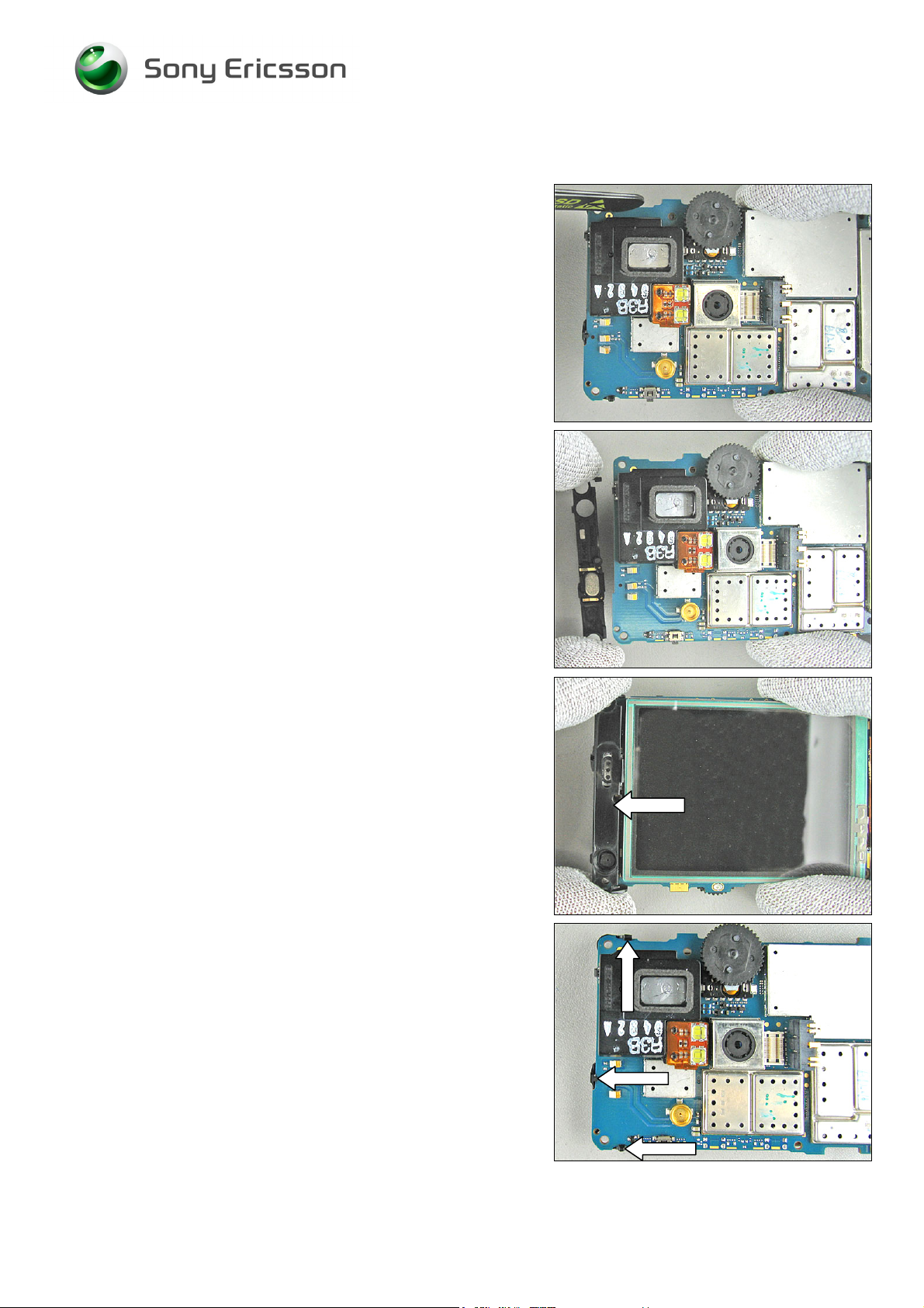
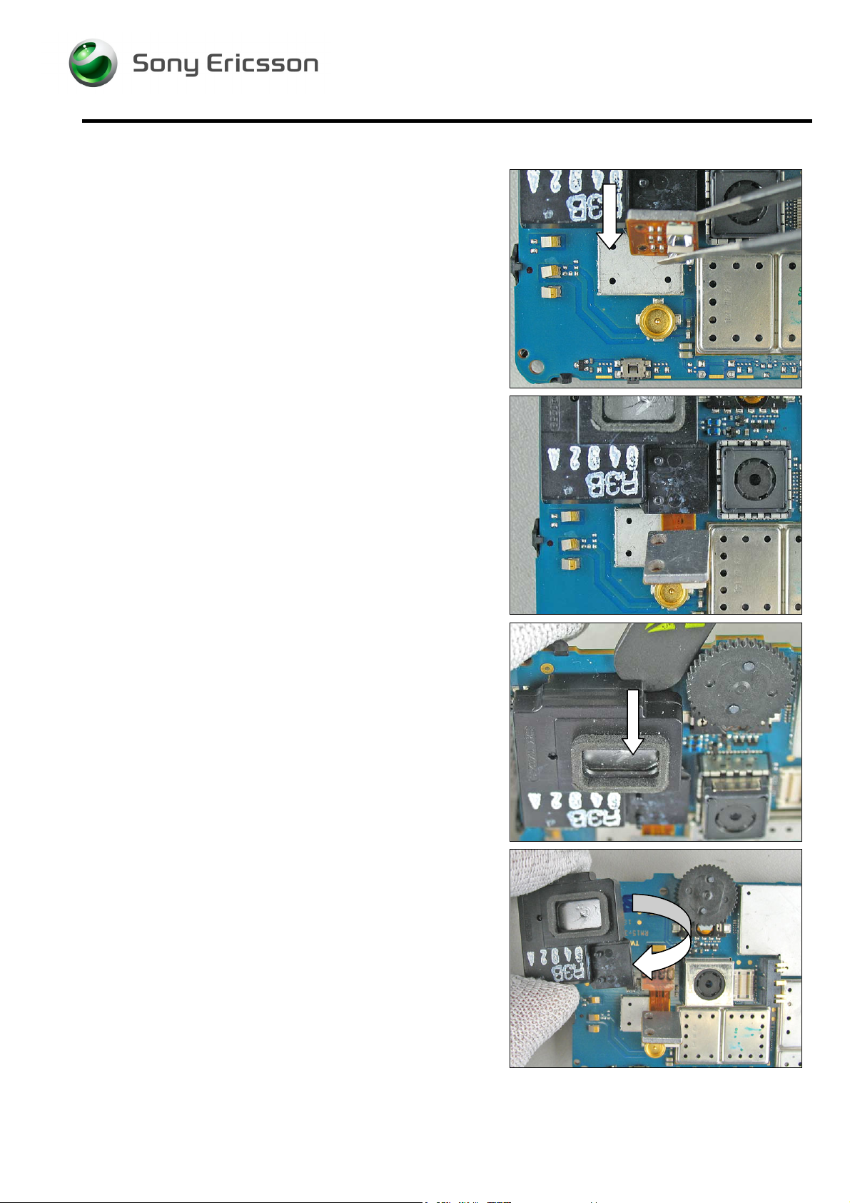
3.11 Ear speaker holder
REMOVAL
Follow the 2.1.1 – 2.1.7 Disassembly instructions!
Start to carefully bend up the latches that hold the Ear
speaker holder with a blunt pair of tweezers.
Remove the old holder.
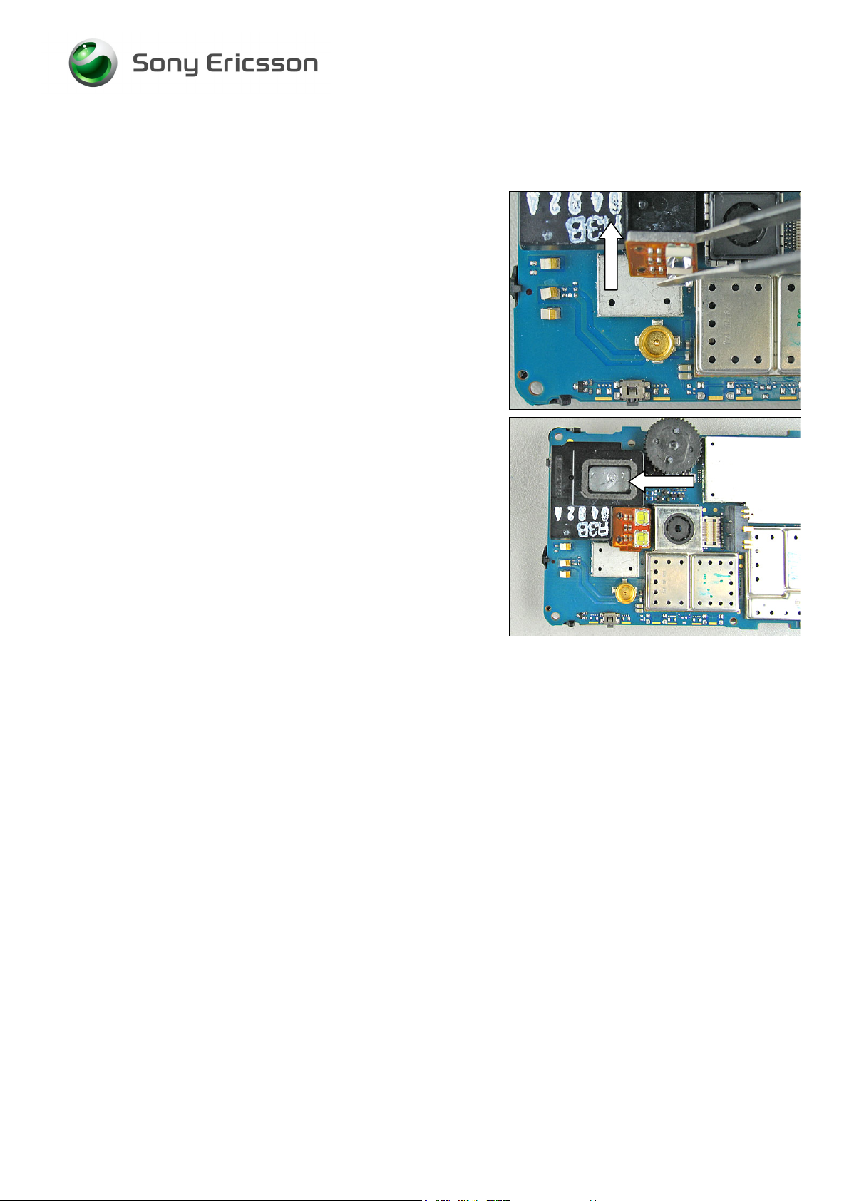
INSTALLATION
Turn the board around.
Press down the new Ear speaker holder.
Check that the three latches are in the correct position.
Follow the 4.1.4 – 4.1.6 Reassembly instructions!
3/000 21-1/FEA 209 544/126 A
© Sony Ericsson Mobile Communications AB
23(68)
Page 24

Working Instruction, Mechanical
3.12 Microphone grommet
REMOVAL
Follow the 2.1.1– 2.1.6 Disassembly instructions!
Remove the old Microphone grommet.
Use a blunt pair of tweezers
INSTALLATION
Assemble a new grommet.
Use your fingers to gently press down the grommet.
Follow the 4.1.1 – 4.1.6 Reassembly instructions!
3/000 21-1/FEA 209 544/126 A
© Sony Ericsson Mobile Communications AB
24(68)
Page 25

Working Instruction, Mechanical
3.13 LCD gasket (small)
REMOVAL
Follow the 2.1.1– 2.1.6 Disassembly instructions!
Remove the old gasket with a blunt pair of tweezers.
INSTALLATION
Reassemble a new gasket with the tweezers.
Gently press on the gasket with our fingers.
Follow the 4.1.2 – 4.2.6 Reassembly instructions!
3/000 21-1/FEA 209 544/126 A
© Sony Ericsson Mobile Communications AB
25(68)
Page 26

Working Instruction, Mechanical
3.14 Dust gasket (system connector)
REMOVAL
Follow the 2.1.1– 2.1.7 Disassembly instructions!
Remove the system connector.
Use a blunt pair of tweezers.
Remove the Dust gasket.
Use a blunt pair of tweezers.
INSTALLATION
Assemble the Dust gasket.
Use a blunt pair of tweezers.
Assemble a new system connector with your fingers.
Press the system connector gently to the bottom of the
PCBA.
Follow the 4.1.1 – 4.1.6 Reassembly instructions!
3/000 21-1/FEA 209 544/126 A
© Sony Ericsson Mobile Communications AB
26(68)
Page 27

Working Instruction, Mechanical
3.15 Vibrator
REMOVAL
Follow the 2.1.1– 2.1.7 Disassembly instructions!
D
O NOT TOUCH THE VIBRATOR CONTACT SPRINGS OR DAMAGE
THE FLYWHEEL
Remove the old vibrator with a blunt pair of tweezers.
INSTALLATION
Press the vibrator to the bottom of the cavity gently with a
blunt pair of tweezers (don’t press on the contact springs).
Check the new contact springs that they are in good
condition and that they are not damaged.
Follow the 4.1.1 – 4.1.6 Reassembly instructions!
!
3/000 21-1/FEA 209 544/126 A
© Sony Ericsson Mobile Communications AB
27(68)
Page 28

Working Instruction, Mechanical
3.16 Liquid intrusion indicator
REMOVAL
Follow the 2.1.2 Disassembly instructions!
Remove the old indicator with a dentist hook.
INSTALLATION
Assemble a new indicator with a blunt pair of tweezers.
Follow the 4.1.6 Reassembly instructions!
Liquid intrusion indicator position on PBA
Follow the 2.1.1 - 2.1.6 Disassembly instructions!
3/000 21-1/FEA 209 544/126 A
© Sony Ericsson Mobile Communications AB
28(68)
Page 29

Working Instruction, Mechanical
3.17 Light guide
REMOVAL
Follow the 2.1.1– 2.1.7 Disassembly instructions!
Remove the old Light guide by pulling it upwards.
Use a blunt pair of tweezers.
INSTALLATION
Assemble a new Light guide.
Gently press down the Light guide to the PCBA with your
fingers.
Follow the 4.1.1 – 4.1.6 Reassembly instructions!
3/000 21-1/FEA 209 544/126 A
© Sony Ericsson Mobile Communications AB
29(68)
Page 30

Working Instruction, Mechanical
3.18 Camera
REMOVAL
Follow the 2.1.1– 2.1.7 Disassembly instructions!
Remove the camera shield with our fingers.
Press down the camera tool (NTZ 112 583).
3/000 21-1/FEA 209 544/126 A
© Sony Ericsson Mobile Communications AB
30(68)
Page 31

Working Instruction, Mechanical
INSTALLATION
Pull up the camera.
INSTALLATION
DO NOT TOUCH THE CAMERA LENS!
Press down the new camera with your fingers.
NOTE
KEYING TAP ON CAMERA
Replacement Instruction continued
Press down camera shield with your fingers.
Follow the 4.1.1 – 4.1.6 Reassembly instructions!
3/000 21-1/FEA 209 544/126 A
© Sony Ericsson Mobile Communications AB
31(68)
Page 32

Working Instruction, Mechanical
3.19 Shielding box
REMOVAL
Follow the 2.1.1– 2.1.6 Disassembly instructions!
Remove the shielding box with your fingers.
3/000 21-1/FEA 209 544/126 A
© Sony Ericsson Mobile Communications AB
32(68)
Page 33

Working Instruction, Mechanical
INSTALLATION
DO NOT TOUCH THE CAMERA LENS!
Reassemble a new Shield with your fingers.
Shielding box reassembled.
Follow the 4.1.1 – 4.1.6 Reassembly instructions!
3/000 21-1/FEA 209 544/126 A
© Sony Ericsson Mobile Communications AB
33(68)
Page 34

Working Instruction, Mechanical
3.20 Shielding box (CIF camera)
REMOVAL
Follow the 2.1.1 – 2.1.7 Disassembly instructions!
Start to carefully bend up the latches that hold the Ear
speaker holder with the backside of a blunt pair of tweezers.
Remove the old holder.
Remove the shielding box with a pair of tweezers.
INSTALLATION
Reassemble a new shielding box with a pair of tweezers.
3/000 21-1/FEA 209 544/126 A
Company Internal
© Sony Ericsson Mobile Communications AB
Approved according to FEA matrix doc number
Page 35

Working Instruction, Mechanical
Replacement Instruction continued
Turn the board around.
Press down the Ear speaker holder.
Check that the three latches are in the correct position.
Follow the 4.1.1 – 4.1.6 Reassembly instructions!
3/000 21-1/FEA 209 544/126 A
© Sony Ericsson Mobile Communications AB
35(68)
Page 36

Working Instruction, Mechanical
3.21 Camera module (CIF)
REMOVAL
Follow the 2.1.1 – 2.1.7 Disassembly instructions!
Start to carefully bend up the latches that hold the Ear
speaker holder with the backside of a blunt pair of tweezers.
Remove the old holder.
Open the Cif camera BtB connector with a front opening
tool.
INSTALLATION
Hold the camera with a blunt pair of tweezers and press
down the BtB connector with your fingers.
3/000 21-1/FEA 209 544/126 A
© Sony Ericsson Mobile Communications AB
36(68)
Page 37

Working Instruction, Mechanical
Replacement Instruction continued
Turn the board around.
Press down the Ear speaker holder.
Check that the three latches are in the correct position.
Follow the 4.1.1 – 4.1.6 Reassembly instructions!
3/000 21-1/FEA 209 544/126 A
© Sony Ericsson Mobile Communications AB
37(68)
Page 38
Working Instruction, Mechanical
3.22 Flash flex
REMOVAL
Follow the 2.1.1 – 2.1.7 Disassembly instructions!
Loosen and fold the Flash flex with a blunt pair of tweezers.
Use the backside of a pair of tweezers and bend until the
acoustic box loosen from the PCBA.
Lift up the acoustic box.
3/000 21-1/FEA 209 544/126 A
Company Internal
© Sony Ericsson Mobile Communications AB
Approved according to FEA matrix doc number
Page 39

Working Instruction, Mechanical
Replacement Instruction continued
Open the Flash flex BtB connector with a front opening tool.
INSTALLATION
Connect the new Flash flex with your fingers.
Reassemble the acoustic box.
Fold down the Flash flex onto the guiding pins on the
acoustic box.
3/000 21-1/FEA 209 544/126 A
© Sony Ericsson Mobile Communications AB
39(68)
Page 40

Working Instruction, Mechanical
Replacement Instruction continued
Flash flex reassembled.
Follow the 4.1.1 – 4.1.6 Reassembly instructions!
3/000 21-1/FEA 209 544/126 A
© Sony Ericsson Mobile Communications AB
40(68)
Page 41

Working Instruction, Mechanical
3.23 Ear speaker
REMOVAL
Follow the 2.1.1 – 2.1.7 Disassembly instructions!
Start to carefully bend up the latches that hold the Ear
speaker holder with the backside of a blunt pair of tweezers.
Remove the old holder.
Remove the Ear speaker with a pair of tweezers.
INSTALLATION
DO NOT TOUCH THE EAR SPEAKER CONTACT SPRINGS !
Reassemble a new Ear speaker and a new gasket with a
pair of tweezers.
Then press down the Ear speaker with your fingers.
3/000 21-1/FEA 209 544/126 A
© Sony Ericsson Mobile Communications AB
41(68)
Page 42

Working Instruction, Mechanical
Replacement Instruction continued
Turn the board around.
Press down the Ear speaker holder.
Check that the three latches are in the correct position.
Follow the 4.1.1 – 4.1.6 Reassembly instructions!
3/000 21-1/FEA 209 544/126 A
© Sony Ericsson Mobile Communications AB
42(68)
Page 43

Working Instruction, Mechanical
3.24 Acoustic box
REMOVAL
Follow the 2.1.1 – 2.1.7 Disassembly instructions!
Use the backside of a pair of tweezers and bend until the
acoustic box loosen from the PCBA.
Loosen and fold the Flash flex with a blunt pair of tweezers.
Lift up the acoustic box.
INSTALLATION
Assemble the new acoustic box.
3/000 21-1/FEA 209 544/126 A
© Sony Ericsson Mobile Communications AB
43(68)
Page 44
Working Instruction, Mechanical
Replacement Instruction continued
Fold down the Flash flex onto the guiding pins on the
acoustic box.
Acoustic box reassembled.
Follow the 4.1.1 – 4.1.6 Reassembly instructions!
3/000 21-1/FEA 209 544/126 A
© Sony Ericsson Mobile Communications AB
44(68)
Page 45

Working Instruction, Mechanical
3.25 Back key
REMOVAL
Follow the 2.1.1 – 2.1.7 Disassembly instructions!
Remove the back key with a blunt pair of tweezers.
INSTALLATION
Assemble the back key with a blunt pair of tweezers.
Follow the 4.1.1 – 4.1.6 Reassembly instructions!
3/000 21-1/FEA 209 544/126 A
Company Internal
© Sony Ericsson Mobile Communications AB
Approved according to FEA matrix doc number
Page 46

Working Instruction, Mechanical
3.26 Operator key
REMOVAL
Follow the 2.1.1 – 2.1.7 Disassembly instructions!
Remove the operator key with a blunt pair of tweezers.
INSTALLATION
Assemble the operator key with a blunt pair of tweezers.
Follow the 4.1.1 – 4.1.6 Reassembly instructions!
3/000 21-1/FEA 209 544/126 A
© Sony Ericsson Mobile Communications AB
46(68)
Page 47

Working Instruction, Mechanical
3.27 Camera key
REMOVAL
Follow the 2.1.1 – 2.1.7 Disassembly instructions!
Remove the camera key with a blunt pair of tweezers.
INSTALLATION
Assemble the camera key with a blunt pair of tweezers.
Follow the 4.1.1 – 4.1.6 Reassembly instructions!
3/000 21-1/FEA 209 544/126 A
Company Internal
© Sony Ericsson Mobile Communications AB
Approved according to FEA matrix doc number
Page 48

Working Instruction, Mechanical
3.28 On/Off key
REMOVAL
Follow the 2.1.1 – 2.1.7 Disassembly instructions!
Remove the On/Off key with a blunt pair of tweezers.
INSTALLATION
Assemble the On/Off key with a blunt pair of tweezers.
Follow the 4.1.1 – 4.1.6 Reassembly instructions!
3/000 21-1/FEA 209 544/126 A
© Sony Ericsson Mobile Communications AB
48(68)
Page 49
Working Instruction, Mechanical
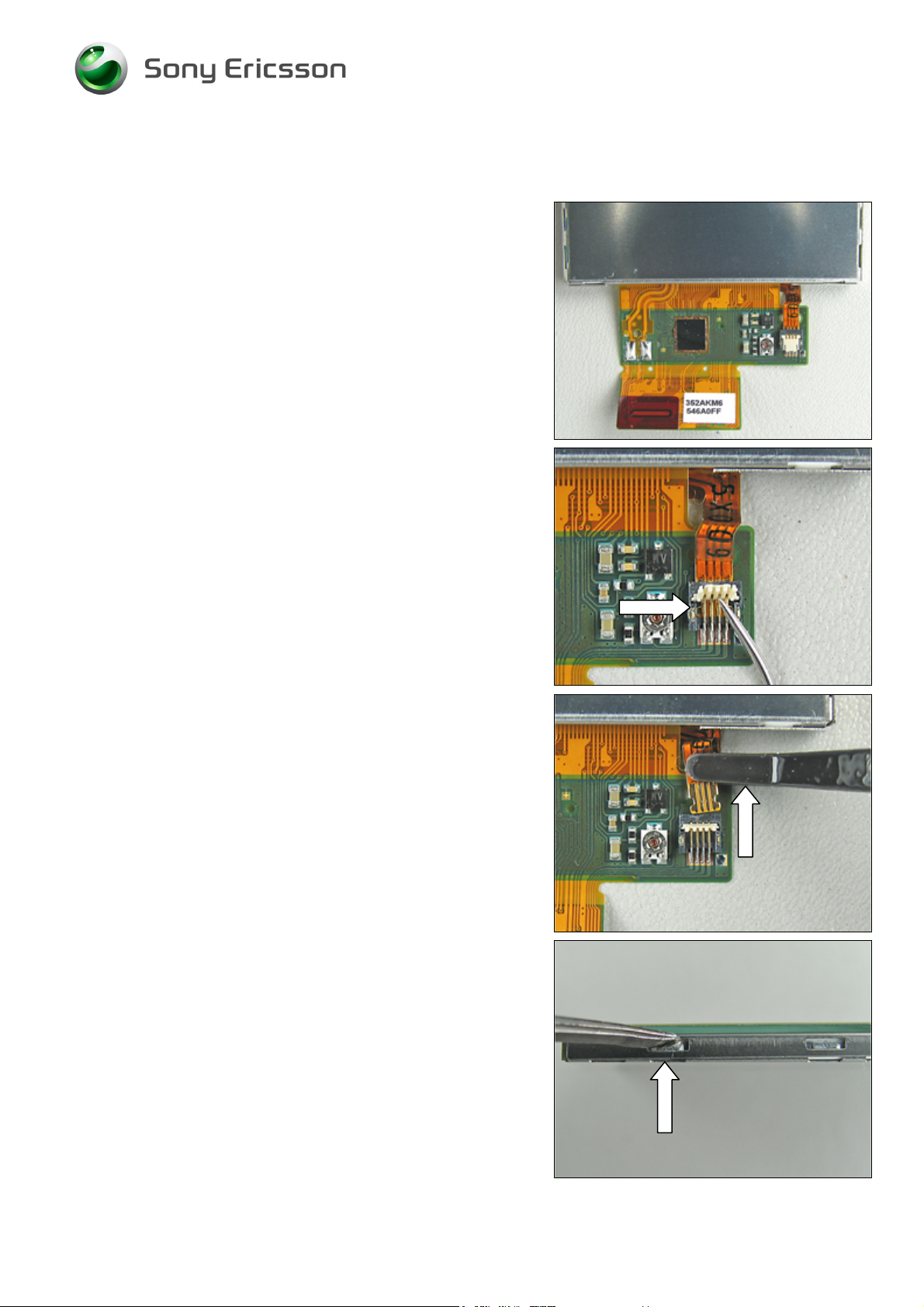
3.29 Touch Panel with Frame
Follow the 2.1.1 – 2.1.9 Disassembly instructions!
Place the LCD like this.
Open the FPC connector with the dentist hook.
Disconnect the touch panel flex film with the flex film
assembly tool.
Use the tweezers, or a small screwdriver, to detach the
touch panel from the LCD.
Start by pressing on one of the three small hooks that
secures the touch panel to the LCD.
Continue until all three become released on this side.
3/000 21-1/FEA 209 544/126 A
© Sony Ericsson Mobile Communications AB
49(68)
Page 50

Working Instruction, Mechanical
Continue to detach the other three hooks on the opposite
side (six hooks in total on the LCD unit) until the touch
panel is released on all sides.
Remove the touch panel by hand.
Touch panel removed.
Turn the new touch panel onto the LCD screen.
O NOT TOUCH THE INSIDE OF THE TOUCH PANEL OR THE LCD
D
SURFACE!
R
EMOVE ANY DUST WITH AN IONIZED AIRGUN OR A BLOWER!
3/000 21-1/FEA 209 544/126 A
© Sony Ericsson Mobile Communications AB
50(68)
Page 51
Working Instruction, Mechanical
Mount the new touch panel on the LCD.
If it doesn’t fit right on, it might help to press on one of the
hooks with the dentist hook.
D
O NOT USE EXCESSIVE FORCE!
Make sure that the touch panel is properly mounted on the
LCD.
Connect the touch panel flex film with the flex film assembly
tool.
Close the FPC connector with the dentist hook.
Properly assembled touch panel and LCD.
3/000 21-1/FEA 209 544/126 A
© Sony Ericsson Mobile Communications AB
51(68)
Page 52

Working Instruction, Mechanical
Don’t forget to remove the protective tape from the new
LCD before the front sub is installed.
O NOT TOUCH THE LCD GLASS SURFACE!
D
R
EMOVE ANY DUST WITH AN IONIZED AIRGUN OR BLOWER!
Follow the 4.1.2 – 4.1.10 Reassembly instructions!
Do these seven tests when the phone is reassembled to
check that the LCD assembly works properly.
(
2_00021-1_FEA209544_126 Test instruction mechanical):
• Touch screen test
• Backlight brightness uniformity
• Contrast
• Display position to check correctly aligned
• Dust inspection
• Dot inspection
• Color check
3.30 Co brand plate
REMOVAL
Remove the Co brand plate with a dentist hook.
3/000 21-1/FEA 209 544/126 A
© Sony Ericsson Mobile Communications AB
52(68)
Page 53

Working Instruction, Mechanical
INSTALLATION
Assemble a new Co brand plate onto the frame.
Press it into the correct position with your fingers.
3.31 Co brand label
REMOVAL
Remove the Co brand label with a dentist hook.
3/000 21-1/FEA 209 544/126 A
© Sony Ericsson Mobile Communications AB
53(68)
Page 54

Working Instruction, Mechanical
INSTALLATION
Assemble the new Co brand label and press down with your
fingers.
3.32 External antenna cap
REMOVAL
Remove the External antenna cap with a dentist hook.
3/000 21-1/FEA 209 544/126 A
© Sony Ericsson Mobile Communications AB
54(68)
Page 55

Working Instruction, Mechanical
INSTALLATION
Reassemble a new External antenna cap with your
fingers.
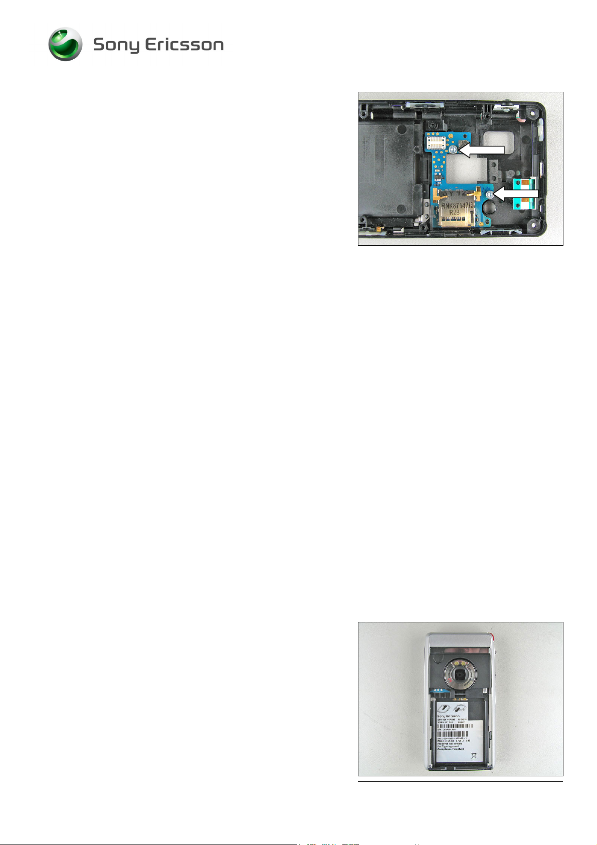
3.33 Sub Pcba
REMOVAL
Follow the 2.1.1– 2.1.7 Disassembly instructions!
Loosen the two screws with a screwdriver (Torx 6).
Remove the Sub pcba.
3/000 21-1/FEA 209 544/126 A
© Sony Ericsson Mobile Communications AB
55(68)
Page 56
Working Instruction, Mechanical
INSTALLATION
APPLY 17 NCM
NTZ 112
288 ( TORX BIT )!
±
2,0 NCM OF TORQUE FOR THE SCREW USING
Place the Sub pcba in the frame.
Assemble and tighten the two screws in the Frame.
Follow the 4.1.1 – 4.1.6 Reassembly instructions!
3.34 Label
REMOVAL
Follow the 2.1.1 Disassembly instructions!
Read the old label and/or write the information into the
“Label make” program before removal
Note the position of the label before removal
Heat up the label by using hot air, if needed.
Carefully remove the label without causing scratches
If there still are residues, clean the surface with isopropyl
alcohol.
3/000 21-1/FEA 209 544/126 A
© Sony Ericsson Mobile Communications AB
56(68)
Page 57

Working Instruction, Mechanical
INSTALLATION
Check that the proper label format is loaded in the Zebra
printer.
Write a new label by using the program “Label make” and
check that the printing is OK.
Take the new label and place it onto the frame as in the
adjacent picture.
NE LABEL ONLY IS ALLOWED!
O
Follow the 4.2.6 Reassembly instructions!
3/000 21-1/FEA 209 544/126 A
© Sony Ericsson Mobile Communications AB
57(68)
Page 58

Working Instruction, Mechanical
4 Reassembly
After replacing a part being listed in Replacements, the instruction of that section usually ends by
directing you to this Reassembly section with a specification of the instructions you have to carry out
in order to reassemble the phone.
REPLACEMENTS
Start
Contents
page
DISASSEMBLY
4.1 Overview
The reassembly is done in the following sequence:
1. PCBA
2. Frame
3. LCD
4. Keyboard flex
5. Keyboard support
6. Keyboard
7. Front
8. Antenna lid
9. Battery
10. Battery lid
REASSEMBLY
Done
3/000 21-1/FEA 209 544/126 A
© Sony Ericsson Mobile Communications AB
58(68)
Page 59

Working Instruction, Mechanical
4.1.1 Torque overview
TIGHTNING TORQUE
Speed set max. 800 rpm
Unit Torque No of screws
Screw SXA 109 5031 (Ø1.4 x 4) 0,11 +/- 0,02 Nm 7
Screw SXA 109 5992 (M1,7 x 6,5) 0,17 +/- 0,02 Nm 2
Screw SXA 109 7094 (M1.6 x 4) 0,17 +/- 0,02 Nm 2
Screw SXA 109 7221 (M1.6 x 3.0) 0,17 +/- 0,02 Nm 2
2x SXA 109 7221
2x SXA 109 7094
7x SXA 109 5031
2x SXA 109 5992
3/000 21-1/FEA 209 544/126 A
Company Internal
© Sony Ericsson Mobile Communications AB
Approved according to FEA matrix doc number
Page 60

Working Instruction, Mechanical
4.1.2 PCBA and Frame
Place the PCBA and Frame beside each other.
BE CAREFUL WITH THE FLEX FILM AND THE BOARD TO BOARD
CONNECTOR
!
Connect the BtB connector to the PCBA.
Start to mount the back key flexfilm.
Back key flexfilm assembled.
3/000 21-1/FEA 209 544/126 A
© Sony Ericsson Mobile Communications AB
60(68)
Page 61

Working Instruction, Mechanical
Reassembly Instruction continued
Connect the BtB connector to the frame.
Place the PCBA into the frame.
APPLY 11 NCM
NTZ 112
1052 (JCIS BIT)!
±
2,0 NCM OF TORQUE FOR THE SCREW USING
Assemble and tighten the four screws in the Frame.
Replace the screw if it’s damaged otherwise it can be
reused.
3/000 21-1/FEA 209 544/126 A
© Sony Ericsson Mobile Communications AB
61(68)
Page 62

Working Instruction, Mechanical
4.1.3 LCD
BE CAREFUL WITH THE FLEX FILM AND THE BOARD TO BOARD
CONNECTOR
Connect the LCD BtB connector to the PCBA.
!
Gently fold the LCD towards the frame until the LCD is in
the correct position.
3/000 21-1/FEA 209 544/126 A
© Sony Ericsson Mobile Communications AB
62(68)
Page 63

Working Instruction, Mechanical
4.1.4 Keyboard flex
BE CAREFUL WITH THE FLEX FILM AND THE BOARD TO BOARD
CONNECTOR!
Connect the Keyboard flex BtB connector to the PCBA.
Place the keyboard support onto the PCBA.
APPLY 17 NCM
NTZ 112
288 (TORX BIT)!
±
2,0 NCM OF TORQUE FOR THE SCREW USING
Assemble and tighten the four screws in the Frame.
Replace the screw if it’s damaged otherwise it can be
reused.
Gently fold down the Keyboard flexfilm.
3/000 21-1/FEA 209 544/126 A
© Sony Ericsson Mobile Communications AB
63(68)
Page 64

Working Instruction, Mechanical
Reassembly Instruction continued
Place the camera key flex into the frame.
Place the Keyboard onto the Keyboard flex.
3/000 21-1/FEA 209 544/126 A
Company Internal
© Sony Ericsson Mobile Communications AB
Approved according to FEA matrix doc number
Page 65

Working Instruction, Mechanical
4.1.5 Front
DON’T FORGET TO REMOVE THE PROTECTIVE TAPE FROM THE
LCD MODULE IF YOU HAVE A NEW LCD MODULE BEFORE
REASSEMBLING OF THE FRAME
Do not touch the LCD glass surface. Blow away dust with
an ionized air gun or blower.
Place the Front onto the frame, start at the keyboard side.
Press down the frame so that the frame and the Front snap
together.
Make sure that there is no gap between the two half’s Visually inspect all around the unit.
3/000 21-1/FEA 209 544/126 A
Company Internal
© Sony Ericsson Mobile Communications AB
Approved according to FEA matrix doc number
Page 66

Working Instruction, Mechanical
4.1.6 Antenna Lid
Place the Antenna lid onto the frame and snap together with
the frame. Start at the top end.
Make sure that there is no gap between the two half’s Visually inspect all around the unit.
APPLY11 NCM
NTZ 112
1052 (JCIS BIT)!
±
2,0 NCM OF TORQUE FOR THE SCREW USING
Assemble and tighten the three screws in the Frame.
Replace the screw if it’s damaged otherwise it can be
reused.
Assemble the External antenna cap.
Assemble the Stylus pen.
3/000 21-1/FEA 209 544/126 A
Company Internal
© Sony Ericsson Mobile Communications AB
Approved according to FEA matrix doc number
Page 67

Working Instruction, Mechanical
4.1.7 Battery lid and Battery
Insert the battery into the frame cavity.
Start at top side, then fold down the battery into the cavity.
Slide on the Battery lid.
The phone is now reassembled.
3/000 21-1/FEA 209 544/126 A
© Sony Ericsson Mobile Communications AB
67(68)
Page 68

Working Instruction, Mechanical
5 Revision history
Rev. Date Changes / Comments
st
A 2007-06-24 1
preliminary release
3/000 21-1/FEA 209 544/126 A
Company Internal
© Sony Ericsson Mobile Communications AB
Approved according to FEA matrix doc number
 Loading...