

Page 1

Mobile Communications
LBI-38965
EDACS BCU/CAL
Billing Correlation Unit/
Centralized Activity Logger
System and Installation Manual
Page 2

LBI-38965
TABLE OF CONTENTS
1. INTRODUCTION............................................................................................................................................................. 4
1.1. BCU FUNCTIONAL DESCRIPTION.................................................................................................................... 5
1.2. CAL FUNCTIONAL DESCRIPTION.................................................................................................................... 5
2. PHYSICAL DESCRIPTION AND COMPATIBILITY.................................................................................................... 6
2.1. PHYSICAL SPECIFICATIONS ............................................................................................................................. 6
2.2. BCU/CAL ARCHITECTURE................................................................................................................................. 7
2.3. COMPATIBILITY.................................................................................................................................................. 9
3. SPECIFICATIONS............................................................................................................................................................ 10
3.1. COMMON BCU AND CAL OPERATIONAL SPECIFICATIONS...................................................................... 10
3.1.1. EDACS System Interface............................................................................................................................... 10
3.1.2. Throughput .................................................................................................................................................... 10
3.1.3. Hard Disk Interface........................................................................................................................................ 10
3.1.4. Operator Interface.......................................................................................................................................... 10
3.2. BCU OPERATIONAL SPECIFICATIONS............................................................................................................ 10
3.2.1. Subscriber Attribute Database....................................................................................................................... 10
3.2.2. Billing Architecture ....................................................................................................................................... 11
3.2.3. BCU Operation Overview ............................................................................................................................. 11
3.2.3.1. RF Channel Usage (Air Time)............................................................................................................. 12
3.2.3.2. Conversations...................................................................................................................................... 12
3.2.3.3. Group Billing Mode ............................................................................................................................ 12
3.2.3.4. Input Messages.................................................................................................................................... 12
3.2.3.5. Time Synchronization.......................................................................................................................... 13
3.2.3.6. Output Records.................................................................................................................................... 13
3.2.3.7. BCU Configuration Files..................................................................................................................... 13
3.2.3.8. Operator Functions.............................................................................................................................. 14
3.2.3.9. Database Elements............................................................................................................................... 14
3.2.3.10. Call Processing.................................................................................................................................. 15
3.2.3.11. Call Detail Records............................................................................................................................ 15
This manual is published by
changes to this manual necessitated by typographical errors, inaccuracies of current information, or improvements to
programs and/or equipment, may be made by
Such changes will be incorporated into new editions of this manual. No part of this manual may be reproduced or transmitted
in any form or by any means, electronic or mechanical, including photocopying and recording, for any purpose, without the
express written permission of
Ericsson GE Mobile Communications Inc.
Ericsson GE Mobile Communications Inc.
Ericsson GE Mobile Communications Inc.
, without any warranty. Improvements and
, at any time and without notice.
Copyright© August 1994, Ericsson GE Mobile Communications Inc.
2
Page 3

LBI-38965
TABLE OF CONTENTS (Cont.)
3.3. CAL OPERATIONAL SPECIFICATIONS............................................................................................................ 16
3.3.1. System Manager Interface............................................................................................................................. 16
3.3.2. Protocol Supported........................................................................................................................................ 16
3.3.3. CAL Operation Overview.............................................................................................................................. 17
3.3.4. Additional Product Features.......................................................................................................................... 17
4. INSTALLATION.............................................................................................................................................................. 18
4.1. HARDWARE INSTALLATION ............................................................................................................................ 18
4.2. SOFTWARE INSTALLATION.............................................................................................................................. 19
4.2.1. Distribution Media ........................................................................................................................................ 19
4.2.1.1. User Configuration Files ..................................................................................................................... 20
4.2.2. Initial Installation .......................................................................................................................................... 24
4.2.2.1. First-Time Configuration..................................................................................................................... 27
4.2.2.2. System Disk Booting........................................................................................................................... 29
4.2.2.3. Proper System Shutdown .................................................................................................................... 30
4.2.3. Software Upgrades ........................................................................................................................................ 31
4.3. CAL TERMINAL SERVER CONFIGURATION.................................................................................................. 31
APPENDIX A EDACS BILLING (CDR) FORMAT............................................................................................................. A-1
APPENDIX B PHYSICAL CONFIGURATION DETAILS ................................................................................................. B-1
APPENDIX C FAULT TOLERANCE................................................................................................................................... C-1
3
Page 4
LBI-38965
1. INTRODUCTION
This manual contains installation instructions, physical and functional descriptions, specifications, and usage information
for the Enhanced Digital Access Communications System (EDACS) Billing Correlation Unit and the Centralized Activity
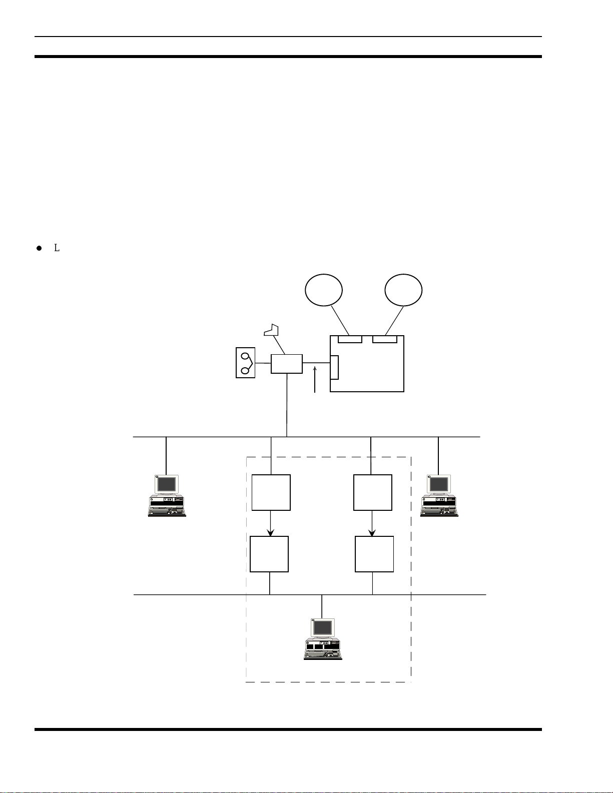
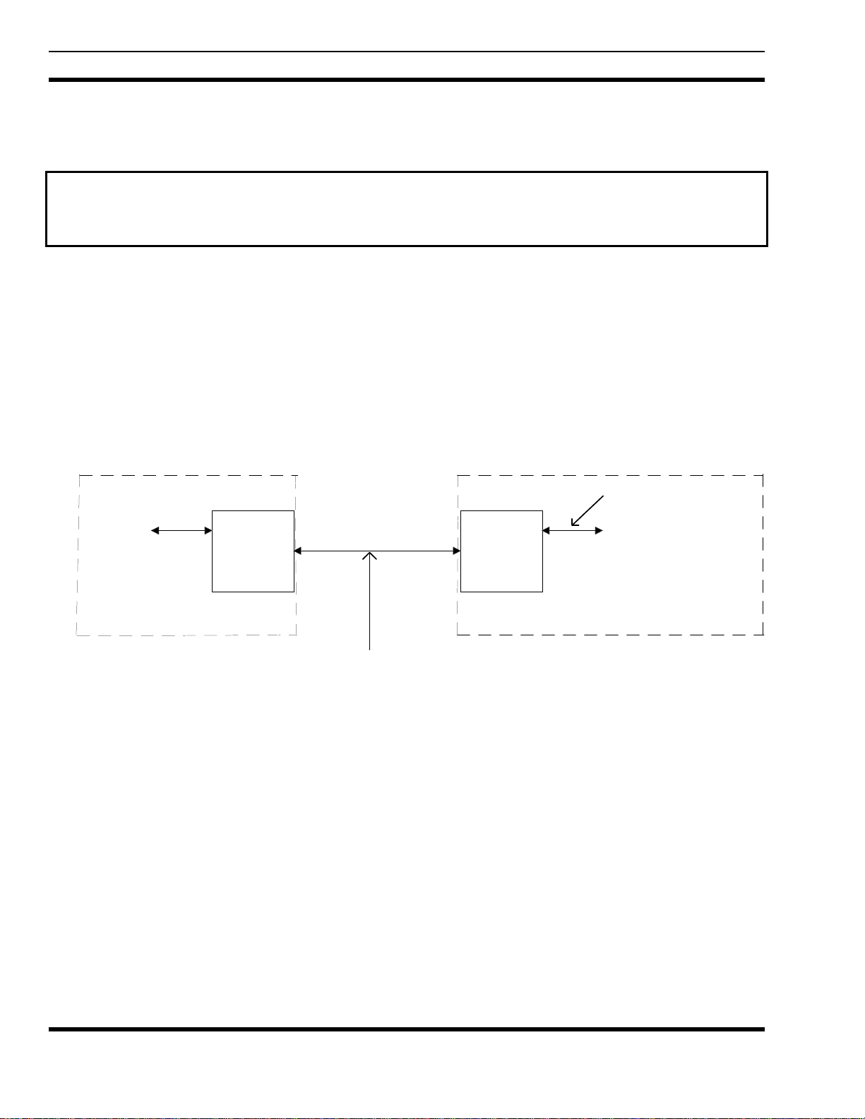
Logger (BCU/CAL). A block diagram of the BCU/CAL is shown below.
The BCU/CAL works as a subsystem attached to an Ericsson GE Integrated Multisite and Console Controller (IMC) and
can be set to operate as a BCU, a CAL, or both. Each IMC node must have its own BCU/CAL.
BCU and CAL are two separate capabilities which can run independently of each other on the same machine, yet still
utilize resources and utilities common to both.
Additional information for BCU/CAL can be found in the following publication:
l
LBI-38967, EDACS Billing Correlation Unit/Centralized Activity Logger User Interface Manual
Ethernet
TCP/IP WAN
Customer
Billing
Computer
Console
Terminal
DAT (Optional)
Em ulex
Terminal
Servers
DEC
Terminal
Servers
BCU
CAL
High-Speed
HDLC Link
16 RS-232
RF
System
Downlink
RS -422
RF
System
MIM
C
A
M
MIM
Area
IMC
Em ulex
Term inal
Servers
16 RS-232
DEC
Terminal
Servers
EDACS
Network
Manag er
DECNet
LAN
System
Mana ger
The dotted lines enclose the CAL-specific interfaces of the BCU/C AL.
Figure 1 - BCU/CAL Architecture
4
Page 5

LBI-38965
1.1. BCU FUNCTIONAL DESCRIPTION
The main function of the BCU is to generate call detail records (CDRs) to be transferred to an external billing system for
invoice generation. To accomplish this, the BCU scans an input stream of activity messages supplied by the IMC, archives
these messages in their raw form, uses those messages which indicate channel assignment and channel drop events to calculate
air time, and then generates the CDR.
Call Types Supported
All EDACS call types except for the following are supported by the BCU:
1. Console calls.
2. Conventional site calls.
3. Local interconnect calls.
4. Non-EDG data calls.
1.2. CAL FUNCTIONAL DESCRIPTION
EDACS system administrators require both site monitor and activity download capabilities. These functions are normally
supported by the System Manager in conjunction with the Site Controller at each Radio Frequency (RF) System. The CAL
provides this capability for EDACS not equipped with a Site Controller.
1. Site Monitor
Provides the system operator at a System Manager terminal with a real-time display of the calls in progress on the RF
channels at the selected trunked system.
2. Activity Download
Call activity and system status information are collected by the CAL and buffered in internal memory. Once an
operator-defined buffer content threshold is exceeded, the CAL initiates a download of buffer contents to the System
Manager. The downloaded information is used to prepare traffic reports on system usage.
In existing EDACS networks, the System Manager communicates with Site Controllers at RF systems using modems and
dial-up or leased line connections, routed thr ough a DECServer terminal server. A communications session is set up via a
DECServer port between the System Manager and the Site Controller. The System Manager associates the DECServer
physical port number with the Site Controller's identity.
Since the IMC is already connected to all the sites, it has centrally available much of the data that individual site
controllers normally output to the system managerfor all the sites. The CAL connects to the IMC and demultiplexes
incoming call activity information messagesthe same messages that the BCU uses for billinginto activity download data
and site monitor data to send to a system manager using site controller protocol.
The CAL uses two Internet Protocol (IP) terminal servers on the local area network (LAN) to communicate with the
System Manager's DECServer(s). Up to 32 RS-232 asynchronous serial connections are available, 16 per terminal server.
One System Manager DECServer port and one IP terminal server port are required per EDACS system being monitored by
CAL.
Call Types Supported
All EDACS call types except for the following are supported by the CAL:
1. Console calls.
2. Conventional site calls.
3. Local interconnect calls.
4. Non-EDG data calls.
5
Page 6

LBI-38965
2. PHYSICAL DESCRIPTION AND COMPATIBILITY
This section outlines the specifications, depicts the physical architecture, and provides compatibility information for the
BCU/CAL.
Software for the BCU and the CAL are merged into one software package. Feature encryption allows or disallows BCU
or CAL functionality. The two products can also run on the same hardware platform with minor additions for CAL.
2.1. PHYSICAL SPECIFICATIONS
General Specifications
BCU/CAL:
ELMA VME System 12 7-slot enclosure with PSU and integral cooling fan
TVME 147 single-board computer with TVME 712/M Transition Module
Formation WANServer fv5310
Maxtor MXT-1240S 1.2 GB 3½" half-height 8.5ms hard disk drive, internal
Teac FD235HS-711 1.44 MB 3½" half-height floppy disk drive, internal
Tape Drive (Optional with BCU only):
Archive/Maynard 4324NP 4/8 GB 3½" half-height 4mm digital audio tape (DAT) drive, internal
Console Terminal:
DEC VT100 or compatible console terminal
Terminal Servers (CAL only)
Emulex Performance Series P2516-SLTL (16 ports per terminal server)
Power Supply
BCU/CAL:
115/230 VAC, 47-63 Hz, 500 W
Physical (EGE Standard Cabinet)
BCU/CAL:
6 rack units: 26.67 cm (10.5 in.) high x 48.26 cm (19 in.) wide x 49.99 cm (19.68 in.) deep
Environmental
Storage Temperature: -40 to +85°C
Operating Temperature: 0 to 40°C (ambient)
Operating Altitude: < 15,000 feet
Shipping Altitude: < 50,000 feet
Relative Humidity: < 90% (non-condensing)
6
Page 7
LBI-38965
2.2. BCU/CAL ARCHITECTURE
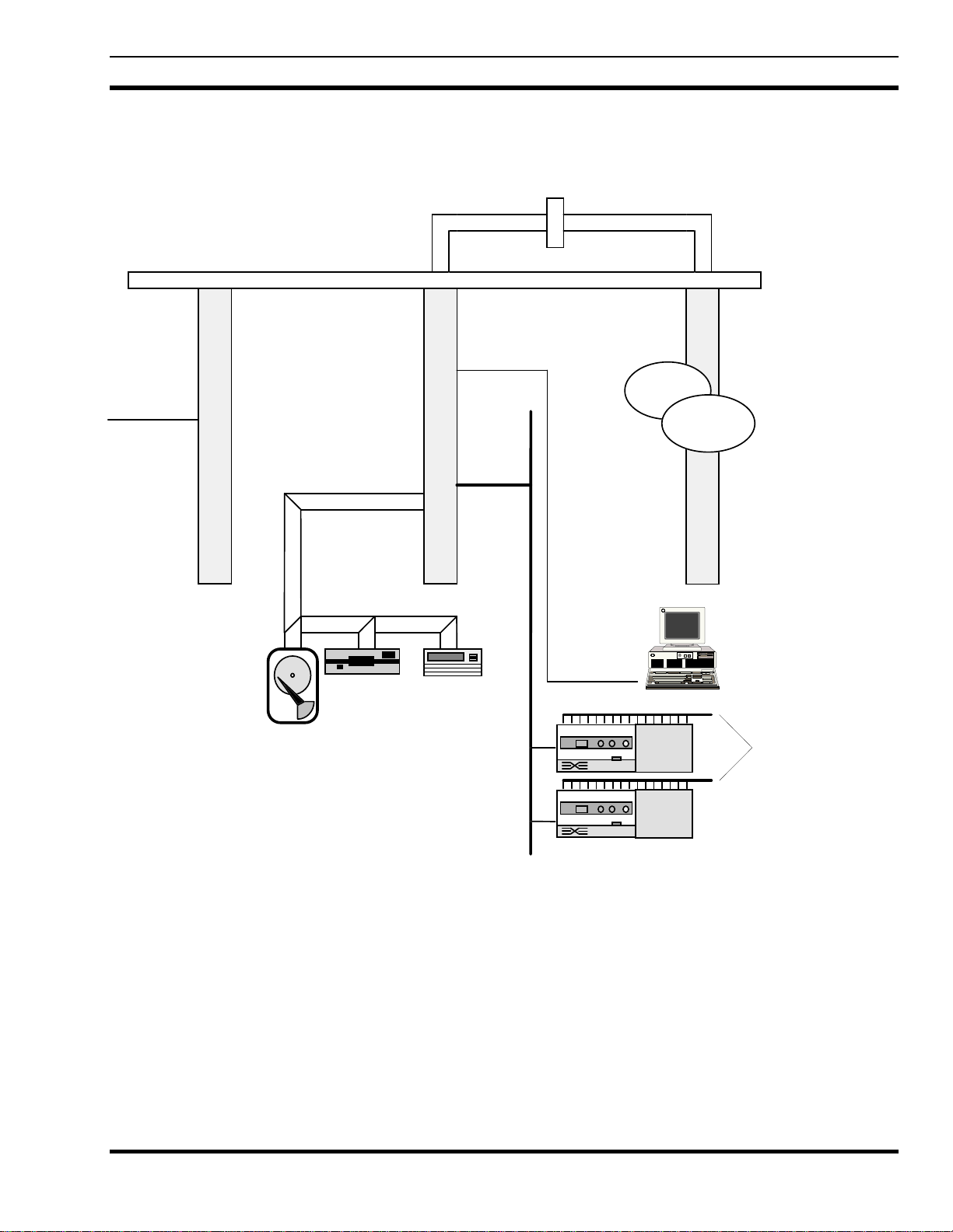
The BCU/CAL's internal architecture is shown in Figure 2. The individual components and their primary functions are
outlined below.
P2 Adapter BoardVMEbus Backplane
RS-232
Appl. SW
HDLC
From CAM
SCSI
Ethernet
LAN
Common
VME
Platform
Formation
WANServer
Communications
Module
Hard Disk
TVME712/M Transition
Floppy
Disk
Module
Tape Drive
Figure 2 - BCU/CAL Architecture
TVME147 CPU
Administrative Terminal
To System Manager
Terminal Servers (CAL Only)
7
Page 8

LBI-38965
The BCU/CAL is based on a VMEbus computing platform with the following components:
CPU
Technico TVME 147 single-board computer based on a 68030 microprocessor
• Supports BCU/CAL application processing
• Interfaces to hard disk, floppy disk, and tape drive via an on-board small computer systems interface (SCSI)
with a connector on the transition module
• Interfaces to the console terminal via an RS-232 serial port with a connector on the transition module
• Network physical connection is 802.3 Ethernet, 10 BASE-15 (Thick Wire). A MAU may be used for
connection to a Thin Wire (coaxial) network
Internal Drives
Hard Disk: 3½" 1.2 GB
• Provides configuration parameter storage
• Provides call detail record (CDR) storage
• Provides raw activity record (RAR) buffering/storage
Floppy Disk: 3½" 1.44 MB
• Used for application program updates
Tape: 3½" 4/8 GB 4mm DAT
• Provides call detail record (CDR) file archival storage
• Provides general purpose file interchange with UNIX
• UNIX Tar format, 512-byte tape block size, no data compression
Communications Module
Formation WANServer fv5310
• Interfaces the BCU/CAL via high-speed high-level data link control (HDLC) link to the Central Activity Module
(CAM) in the Integrated Multisite and Console Controller (IMC)
System Manager Interface (CAL only)
One or Two Emulex Performance Series P2516-SLTL Terminal Servers
• Communicates with the BCU/CAL over the network and with the System Manager over RS-232
• Converts between transmission control protocol (TCP) sockets and asynchronous serial protocol
8
Page 9

LBI-38965
2.3. COMPATIBILITY
The BCU/CAL software is compatible with the following IMC and System Manager versions:
• IMC Software V4.01 and later
• IMC CAM Controller Board (P/N 19D903299P3)
• Networks/Data VME Controller ROM V1.03
• MicroVax System Manager Software V3.01 and later (CAL only)
The System Manager Software version requirement applies only to the CAL feature. The BCU feature operates
independent of the System Manager. Thus, the BCU is “compatible” with any System Manager software
version.
Backwards Compatibility
The BCU/CAL will function with IMC software versions down to V3.04, with minor performance degradation. T he
following features are not available with IMC software versions older than V4.01:
BCU/CAL
• The User Interface “stats” command will not provide information regarding queued, denied, system busy, and
convert-to-callee channel events.
CAL-Specific
• Activity records and site monitoring will not reflect queued, denied, system busy, and convert-to-callee channel
events.
• The site monitor will not provide current control channel indication.
9
Page 10

LBI-38965
3. SPECIFICATIONS
3.1. COMMON BCU AND CAL OPERATIONAL SPECIFICATIONS
3.1.1. EDACS System Interface
The BCU/CAL interfaces to EDACS via a full duplex port supporting high-level data link control (HDLC) protocol. The
BCU/CAL will adapt to the data transmission rate to which the Central Activity Module (CAM) is set to operate (6 4K or
360K, selectable via CAM dip switches).
BCU/CAL Input Data
Each raw activity record (RAR) contains the following information:
1. Day and time of event accurate to ±0.1 second
2. Type of event (i.e., assignment or drop)
3. Call type (individual clear voice, group clear voice, individual digital voice, group digital voice, data, etc.)
4. Site number or console number
5. Channel number (to match assignments with drops)
6. Caller ID
7. Callee ID
8. Digitally dialed PSTN digits for outgoing interconnect calls
Note: The dialed digits correspond to the digits sent by a radio to the interconnect system to initiate an
interconnect call; dual tone multi-frequency (DTMF) overdial digits sent by the radio once an interconnect call
is in progress are not registered by the BCU.
3.1.2. Throughput
The BCU/CAL's interface to the IMC is capable of receiving a peak data rate of 192 raw activity records (RARs) per
second. A buffer stores incoming RARs at the peak rate of 192 RARs per second for a minimum of 300 seconds (5 minutes).
3.1.3. Hard Disk Interface
The BCU/CAL provides nonvolatile storage of the BCU/CAL operating software, CDRs, system configuration data,
system defaults, and subscriber attributes. The hard disk provides concurrent support of call record processing and the
operator interface.
3.1.4. Operator Interface
Most BCU/CAL operator functions are capable of being performed without impacting or reducing the capacity of the call
processing functions below specified rates. Refer to the User Interface Manual, LBI-38967, for further information.
3.2. BCU OPERATIONAL SPECIFICATIONS
This section outlines the specifications that are unique to the BCU personality.
3.2.1. Subscriber Attribute Database
Each system subscriber and each group defined on the system is assigned a record in the subscriber attribute database.
This database supports a maximum of 16,383 individual subscribers and a maximum of 2048 groups.
10
Page 11
LBI-38965
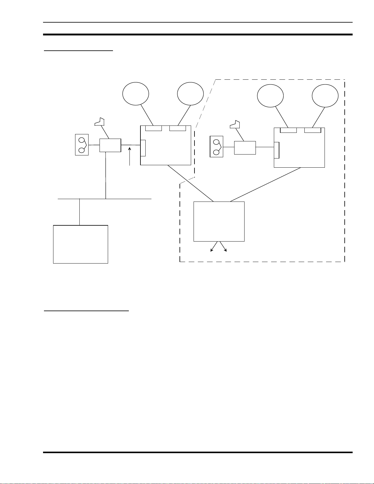
3.2.2. Billing Architecture
The EDACS billing system architecture is shown in Figure 3. Each IMC is connected to a BCU/CAL via a high-speed
serial communications link using HDLC protocol.
DAT (Optional)
Ethernet
TCP/IP WAN
Customer
Billing
Mainframe
Console
Terminal
BCU
RF
System
Downlink
High-Speed
HDLC Link
RF
System
Console
Terminal
Area
IMC
MIM
DAT (Optional)
BCU
MIM
C
A
M
RF
System
MIM MIM
Area
C
A
M
IMC
RF
System
StarGate
To other IMCs
The dotted lines enclose one optional setup for a StarGate (multi-node) billing architecture.
Figure 3 - Billing Architecture
3.2.3. BCU Operation Overview
Each RF system sends all call information to the IMC via the downlink. This is true for single-channel autonomous
trunking (SCAT), Conventional Network Interface (CNI), basic EDACS, and RF systems operating in failsoft mode.
All call activity information messages received by the IMC are collected by the Central Activity Module (CAM), where
each call message is time stamped. These messages, called raw activity records (RARs), are then passed via the high-speed
serial link to the BCU/CAL.
If activity logging is enabled, the BCU first archives a copy of each RAR received. The BCU then examines each RAR
and uses the time stamp values to determine the length of each call. The actual billing algorithm is quite complex and
depends on the BCU's keeping a memory of outstanding calls. The output of the billing algorithm is stored to a regular disk
file as a series of call detail records (CDR). Activity logging of RARs is a diagnostic capability not required for normal BCU
functionality. RAR activity logging consumes disk space and can result in degraded system throughput. Although the feature
is provided, its use is strongly discouraged for most users.
The CDR format is compatible with Cincinnati Bell Information System’s (CBIS) Cellware billing software.
11
Page 12

LBI-38965
3.2.3.1. RF Channel Usage (Air Time)
The basic unit of RF channel usage for billing purposes is a channel assignment. One or more working RF channels is
assigned in response to a request from a subscriber unit (mobile radio, data terminal, etc.). Each channel assignment event
results in air time, which is defined as the period of time during which the RF channel or group of channels is in use, repeating
the signal from a subscriber unit. If the system is operating in transmission trunke d mode, one channel assignment occurs
each time the unit is keyed and unkeyed. In a multisite network, more than one channel assignment can occur in a single
call—since multiple sites can participate in a call—and a channel is used on each participating site. The air time for such a
call is defined as the sum of the air time associated with all of the channel assignments occurring in that call.
In a multiple node network (StarGate or MultiLink), a single call may involve channel assignments on sites on more than
one node. In theory, these channel assignments are part of the same call. In practice, the BCU deals with data at the node
level and does not correlate channel assignment air time from remote nodes. A multiple node call is identified by the
StarGate interface ID as the site ID in the CDR; this facilitates the correlation of records across nodes in the external billing
system.
3.2.3.2. Conversations
If a CDR were created for each call, the data storage requirements for the BCU/CAL would be excessive. For this
reason, a different unit of RF channel usage, called a conversation, has been defined. A conversation includes one or more
calls. Calls are summed into conversations based on the subscriber (radio) units participating in the calls and the duration of
the time interval between the end of one call and the beginning of the subsequent call. The criteria for inclusion in a
conversation are explained in detail below.
Grouping Calls
A set of calls may be grouped into a conversation only if each call involves the same participants and is of the same call
type as all other calls in the set. For group calls, only calls made with the same Group Identification (GID) may be linked. In
this case, the Logical Identification (LID) of the caller is irrelevant, except for the LID of the first caller in a sequence (this is
explained in the next subsection). For individual calls, the caller's LID must be the same as either the caller's or the callee's
LID in every other call in the set.
Broken Call Sequences
A set of calls must occur in an unbroken sequence. A sequence is broken when one of the call participants calls a nonparticipant. For individual calls, this means that either the caller or the callee from the first call in the sequence calls some
third party, either a group or individual. For group calls, the sequence is broken if the caller from the first call in the sequence
calls a different group or an individual. Note that a subscriber unit may participate in multiple group conversations
overlapping in time, as long as that unit was not the first caller in at least one of the conversations.
A sequence of calls is also broken when the time interval separating the end of one call and the beginning of the
subsequent call in the sequence exceeds an arbitrary value. This value is called the pseudo hang time and is configurable on a
unit or group basis in the BCU.
3.2.3.3. Group Billing Mode
A group call may be charged to the caller or to the group. The CDR includes a flag which indicates which party to bill.
The choice is determined by a billing mode associated with each group ID or by the default billing mode. Individual calls are
always charged to the caller, except for land-to-mobile interconnect calls and incoming data calls. In each of these cases, the
ID of the caller (or sender of the data) is unknown; thus, the call must be billed to the callee.
3.2.3.4. Input Messages
Input to the BCU consists of a stream of activity messages. As a minimum, the messages include all channel assignment
events and channel drop events generated on EDACS. This includes channel assignment and drop from the Jessica Private
Branch Exchange (PBX) Gateway and StarGate interfaces.
12
Page 13

LBI-38965
Channel assignment and channel drop messages contain the following information:
• Date and time of event to the nearest tenth of a second
• Type of event (i.e., assignment or drop)
• Call type (individual clear voice, group clear voice, individual digital voice, group digital voice, data, etc.)
• Site number or console number
• Channel number
• Caller ID
• Callee ID
3.2.3.5. Time Synchronization
The time of channel event value is derived from the IMC's internal clock. This is slaved to the MOM-PC clock, which
can be synchronized externally from a WWVB signal, via a Spectracom clock unit. This unit is available as an option to the
MOM-PC. The Spectracom unit includes an internal high-stability reference clock, which maintains synchronization even in
the event of loss of the WWVB signal for an extended period. This configuration ensures that RAR timestamps are accurate
at all times.
3.2.3.6. Output Records
The BCU creates CDRs by processing the input messages due to channel assignments and channel drops. The format of
a CDR record entry is discussed in detail in Appendix A. Each CDR records the following information about each
conversation:
• The Logical Identification (LID) of the caller
• The identity of the callee (either LID or GID)
• The location (node, site, and channel number) of each RF channel involved in the conversation
• The call type (individual clear voice, group clear voice, individual digital voice, group digital voice, data, etc.)
• A flag indicating which party to bill (caller or callee)
• The start time of the first call
• The elapsed time from the start time until the end of the final call
• The number of channel assignments included in the conversation
• The total accumulated air time (Note that this is not the same as the elapsed time because of the pseudo hang
time, and the effect of multiple channels per call.)
3.2.3.7. BCU Configuration Files
The BCU uses binary configuration files to store various configuration values. The file names and their contents are as
follows:
File Name Contents
SYSTEM.BIN Specifies system parameters, default pseudo hang times, and billing modes.
UNIT.BIN Specifies the pseudo hang time associated with each LID.
GROUP.BIN Specifies the pseudo hang time and the group billing mode associated with each GID.
These files are located in the 1.2/cnfg directory.
Since they are stored in binary form, these configuration files can be modified only by using the BCU/CAL Configuration
Service (BCS) program, which is described in the User Interface Manual (LBI-38967). The BCU is able to operate with no
terminal input by using all default values for configuration parameters.
Pending development by Ericsson GE of a system-wide database management strategy, there is a method by which the
BCU configuration "database" can be maintained without using BCS to configure each unit manually.
13
Page 14

LBI-38965
The three configuration file s can be created b y running BCS on a BCU/CAL used as a master. T hen, these files can be
copied to the appropriate directory (1.2/cnfg) on a target BCU, and the target will assume the same configuration values.
Changes specific to the target must be made either b y running BCS on the target or by making the changes on the master,
copying the configuration files to the target, then reversing the changes to restore the master to its baseline configuration.
NOTE
To copy or delete the configuration files from a BCU/CAL, you must NOT b e running BCS o n that system. BCS keep s all
the configuration files open while it is running, thereby preventing them from being deleted or overwritten.
3.2.3.8. Operator Functions
An EDACS system operator is able to perform the following functions locally or remotely using a terminal interface
program running on the BCU/CAL:
• Input of default configuration database.
• Default pseudo hang time.
• Default group billing mode.
• Input of configuration data for individual LIDs and/or GIDs to override the default configuration database.
(Configuration data may be input for an individual ID or range of IDs.)
- LID pseudo hang time.
- GID pseudo hang time.
- GID group billing mode.
• Creation of a magnetic tape archive of CDRs.
• Transfer CDR files from the hard drive to the floppy drive.
Refer to LBI-38967 for a detailed explanation of the available operator functions.
3.2.3.9. Database Elements
This section describes the elements of the BCU's configuration database.
Default Data
A set of subscriber default attributes maintained on the system contains the following information:
1. Default unit pseudo hang time (seconds)
2. Default group pseudo hang time (seconds)
3. Default group billing mode (caller or group)
4. Default data call pseudo hang time (seconds)
Unit Data
Each subscriber can be assigned a record in the subscriber attribute database. This record contains the following
information: Pseudo_Hang-Time (seconds).
Group Data
Each group defined on the system shall be assigned a record in the subscriber attribute database containing the following
information:
1. Group pseudo hang time (seconds)
2. Billing mode (group or caller)
14
Page 15

LBI-38965
3.2.3.10. Call Processing
This section contains specifications on the BCU's call processing capability.
CDR Processing
A record of each conversation is maintained by the system. A conversation is a collection of calls detailed by RARs that
have been correlated based upon call participants and caller pseudo hang time. Each CDR contains the following
information:
1. Caller billing ID (BID)
2. Callee BID or GID (group ID)
3. Call type (individual, group, Digital Voice, data, interconnect, etc.)
4. Bill flag (caller or callee)
5. Identification of each RF channel (node, site, and channel)
6. Start time of the first call
7. Number of channel assignments included in the conversation
8. Total elapsed time from start time to end of final call
9. Total accumulated node air time to within ±0.5 seconds
10. PSTN number dialed on outgoing interconnect calls
11. PSTN line number on incoming interconnect calls
Call Processing CDR Output
The call processing software redirects file output to a new file when the current file being written to exceeds a maximum
size. The system administrator can set this maximum size.
CDR Storage Requirements
The BCU is capable of storing all CDRs from the previous 30 days on its internal hard drive. CDR files are maintained
on the system for a programmable time period.
CDR Processing Errors
The call processing software recovers automatically from the following error conditions:
1. Link time-out exceeded
2. Unmatched channel drops
3. Unmatched channel assignments
4. CAM hardware reset
5. WANServer reset
RAR Storage Options
The system administrator can choose either to store all RARs to the hard drive or to discard RARs after use by the CAL
and/or BCU processing software.
RAR Storage Requirements
The BCU/CAL can store all raw activity records for the previous 24 hours.
3.2.3.11. Call Detail Records
A CDR is a series of ASCII characters terminated by a newline (NL) character. The records are variable length, but they
contain a fixed length segment, which is always present, followed by zero or more suffix segments.
There are two types of suffix segments. The first is an additional site segment, which identifies the sites and channels
used in a multisite call. The second type of suffix is a PSTN phone number field, which is append ed to a mobile-originated
interconnect call record and contains the digits dialed by the caller.
15
Page 16
LBI-38965
3.3. CAL OPERATIONAL SPECIFICATIONS
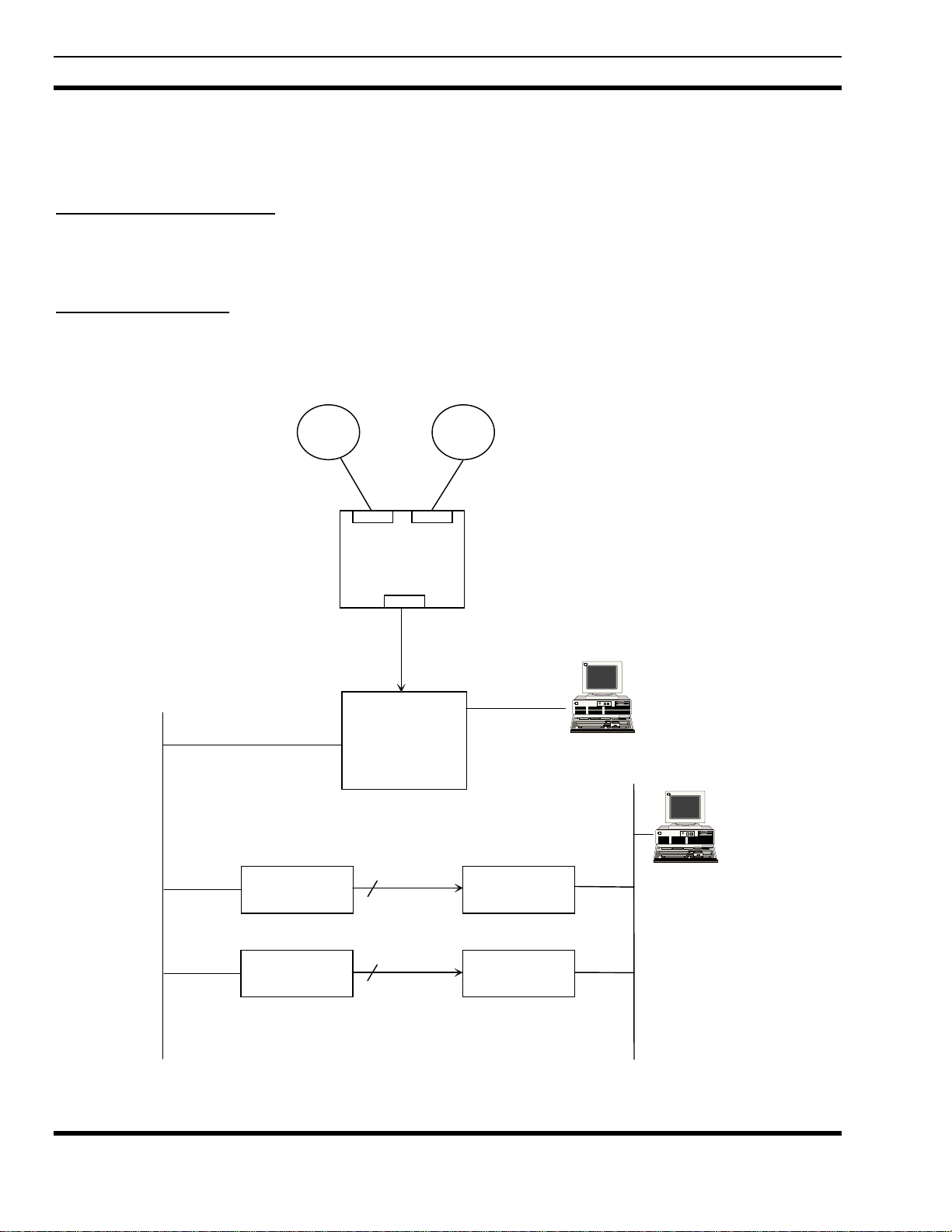
This section outlines the specifications that are unique to the CAL personality. Refer to Figure 4 for the CAL
architecture.
3.3.1. System Manager Interface
The CAL interfaces to the System Manager's DECServer(s) via one or two terminal servers capable of supporting up to
32 independent asynchronous RS-232 serial connections. The ports on the CAL's terminal servers are connected to the ports
on the System Manager's DECServers via RS-232 cables.
3.3.2. Protocol Supported
The CAL is capable of communicating with the System Manager using the System Manager-to-Site Controller (SM-SC)
and Site Controller-to-System Manager (SC-SM) protocol defined in EDACS Protocol Specification, System Manager/Site
Controller Version 1.1.
TCP/IP
LAN
RF
System
MIM
MIM
Area
IMC
CAM
High-Speed H DLC
Link (RS-422)
Centralized
Activity
Logger
(C A L )
RF
System
RS-232
CAL C onsole T erm inal
16
Em ulex
Te rmina l S e rv e rs
Emulex
Te rmina l S e rv e rs
DEC
16 RS-232
16 R S-2 32
Term inal Servers
DEC
T erm inal Serv ers
Figure 4 - CAL Architecture
System
Ma nager
DECNet
LAN
Page 17

LBI-38965
3.3.3. CAL Operation Overview
As new RARs enter the system, they are dispatched to an appropriate site handler which reformats and queues the data.
When the number of activity records queued exceeds a threshold value obtained from the System Manager at startup, a
download request is sent to the System Manager. At any point, the System Manager may log in to the site obj ect and request
it to purge its queue of activity messages, start/stop download of activity messages, or start/stop the transmission of
monitoring messages.
3.3.4. Additional Product Features
Network File System
The BCU/CAL can be licensed to function as a network File Server (NFS). This feature allows the BCU/CAL system disk to
be mounted by client hosts, such as a billing mainframe computer. The NFS feature is provided at no charge for units
licensed for BCU operation. It may be purchased as an additional feature for the CAL.
17
Page 18
LBI-38965
4. INSTALLATION
4.1. HARDWARE INSTALLATION
CAUTION
Turn off the power before removing or installing VMEbus boards. Removing or reinstalling the boards while the po wer is on
will damage the boards.
This section describes the physical installation of the BCU/CAL. Other configuration is performed during manufacture,
and the information necessary is provided in Appendix B.
Follow these steps to connect a BCU/CAL to an IMC for the first time (except where indicated otherwise, these steps
apply to all configurations; BCU only, CAL only, or BCU and CAL):
Using the LAPB cable provided, connect the BCU/CAL's CAM control port 0, a female DB-25 connector located on the
rear of the BCU enclosure, to the lower connector on the IMC backplane which corresponds to the slot in which the CAM
resides. The cable is keyed so that it fits properly only when it is correctly oriented.
BCU/CAL Equipment Rack
852327G1
BCU/CAL
CAM Control
Port 0
Data Concentrator at
BCU/CAL Equipment Rack
Next, connect the console terminal to the female DB-25 connector labeled "SERIAL PORT 1/CONSOLE" on the
TVME-712/M transition module located in the rear of the BCU/CAL enclosure. (For reference, the BCU/CAL is delivered
preconfigured from the factory in a 19-inch rack.) Connect the other end of this cable to the console terminal's "host" port, or
equivalent. If a PC is used as the console terminal, then a DB-9 adapter may be needed. In either case, the serial cable for the
console is wired straight-through.
Configure the console terminal for the communications parameters below.
J1
J14 J9
19D903880P120-129
Figure 5 - BCU/CAL to IMC
903531P1
Audio Concentrator
at IMC
IMC Equipment Rack
19D903628P71
P2 P1
J1
CAM Control
This will be plugged into
PA2XX on the backplane
and will correspond with
the slot in which the CAM
control card is located.
P72
P73
18
• 9600 Baud
• No Parity
• 8 Data Bits
• 1 Stop Bit
Page 19

LBI-38965
If the BCU/CAL is being connected to a network, plug a MAU (either coaxial or twisted pair) into the 15-pin female
connector labeled "ETHERNET" on the TVME-712/M transition module on the rear of the BCU/CAL enclosure and attach
the MAU to the network. If the BCU/CAL is being connected to a 10BASE-15 (Thick Ethernet) network, no MAU is
required. Attach the transceiver cable directly to the 15-pin connector on the transition module.
If CAL is to be enabled for this installation, then connect the Emulex P2516 terminal server(s) to the same network
segment to which the BCU/CAL is connected and switch on the power. Be sure to wait 5 minutes after applying power to the
P2516 before continuing on to the next step. Even though it is a separ ate unit, the terminal server is an integral part of the
CAL. The terminal server must be situated near the VAX System Manger's terminal server (DECServer). The ports on the
P2516 connect to the ports on the DECServer with RS-232 cables. The port connections will be different for each
installation, depending on which sites will be monitored by CAL.
Turn on all power switches and wait for approximately 2 minutes. The following indications signify that the BCU/CAL
is functioning properly:
• The red LEDs on the BCU/CAL are not illuminated.
• The amber "STATUS" LED on the TVME-147 is lit dimly or is flashing.
• The green "RUN" LED on the fv5310 is illuminated.
• The console terminal displays the message
If any of these conditions are not met, then double-check the connections and try to restart the BCU/CAL by switching
the power off, waiting 15 seconds, and switching on the power again. If normal operation is not achieved, then leave the
power switched on and the network connected. It may be possible to diagnose the BCU/CAL remotely over the network.
Login:
The personality of the BCU/CAL unit is set during manufacture, but can be changed by using the product utility, which
can be run from the BCU/CAL command line after logging in. For details on this utility, see the User Interface Manual (LBI-
38967).
For BCU/CAL operation via the console terminal, refer to the User Interface Manual (LBI-38967).
4.2. SOFTWARE INSTALLATION
The following section describes the software distribution, installation, and configuration of the BCU/CAL application(s).
4.2.1. Distribution Media
The BCU/CAL software is distributed on four 1.44Mb MS-DOS compatible floppy diskettes. The first three disks
contain Ericsson GE executable code, supplied in ASCII S-Record format. The head (first few lines) of the files on these
disks identifies the software revision of the distribution.
The fourth disk (Installation Disk 4) contains template ASCII configuration files which are intended to be modified by
the end user.
The table below summarizes the contents of the distribution disks.
Table 1 - BCU/CAL Installation Diskettes
Installation
Diskette
1 LOADER.SX - “Bootstrap” loader for the BCU/CAL application.
2 BC_A.SX - First segment of the BCU/CAL executable image.
3 BC_B.SX - Second segment of the BCU/CAL executable image.
4 Product configuration files to be modified by the BCU/CAL end user.
Contents
19
Page 20

LBI-38965
The following table summarizes the configuration files contained on Installation Diskette 4. These files are provided in
template form, and should be modified to suit customer-specific requirements. The files are in MS-DOS format, and may be
edited with any ASCII text editor.
Table 2 - BCU/CAL Configuration Diskette
File Name Usage
IP.DAT Defines the IP address, subnet mask, and host name of the BCU/CAL.
ROUTES.DAT Defines network routing paths between the BCU/CAL and other hosts on the customer’s
network. Syntax is similar to the UNIX /etc/gateways file.
EXPORTS.DAT Defines the BCU/CAL NFS export list for units which have been purchased with the NFS file
server software feature. File contents specify NFS client IP address(es) and the BCU/CAL
directory(s) they are privileged to mount. Syntax is similar to the UNIX/etc/exports file.
CAL.DAT Defines the site interfaces from CAL to the EDACS System Manager. Contents of this file
are directly related to configuration parameters which must be set on the Emulex Terminal
Server(s).
4.2.1.1. User Configuration Files
This section discusses the contents of the user configuration files contained on Installation Diskette 4. These files should
be modified according to customer requirements. When changes are made to the file contents, the BCU/CAL should be
rebooted with the diskette installed in the floppy drive.
4.2.1.1.1. IP.DAT Configuration File
The IP.DAT configuration file is provided in template form on Installation Diskette 4. This file is common to both the
BCU and CAL feature licenses. It defines the unit's Internet parameters on the end user's local or wide area network. The
following three lines show the default contents of the IP.DAT file. The values shown in bold print should be modified by the
end user. Only “space” characters should be used between the parameter keywords and the end user assigned values. Any
errors detected in the file will be displayed on the local console during system boot.
#######################################################################
#######################################################################
IP_ADDRESS
HOST_NAME
SUBNET_MASK
Parameter Meaning
IP_ADDRESS IP address of the BCU/CAL, in Internet dotted-decimal notation.
HOST_NAME Host name of the BCU/CAL, up to 32 characters long.
SUBNET_MASK IP subnet mask for the BCU/CAL. Specified as 8 hexadecimal digits, in upper case.
4.2.1.1.2. ROUTES.DAT Configuration File
The ROUTES.DAT configuration file specifies network routing paths to be established at system boot. Typically, this
file will only be required if the BCU/CAL is connected to a wide area network, where routers exist between the unit and other
customer host facilities. The template file contains a few example routes, which are commented out (i.e., preceded with a #
character). If no network routing is required, this file may be omitted, or left unaltered.
147.117.37.226
bcu01
FFFFF000
Table 3 - IP.DAT File Parameters
A log file (1.2/log/routes.log) is generated on each system boot. This file contains a summary of successful routing
additions, as well as any errors detected during processing of the ROUTES.DAT file.
20
Page 21

LBI-38965
Network routes are specified in the following form:
type destination_ip gateway gateway_ip
Table 4 - ROUTES.DAT File Parameters
Parameter Meaning
type
destination_ip IP address of the destination host or network, in Internet dotted-decimal notation.
gateway Keyword indicating that the next field is that of the gateway node.
gateway_ip IP address of the gateway to be used to communicate with the host address specified by
Parameter specification is not case-sensitive, and is parsed (i.e., net is equivalent to network). White space and/or tabs
may separate the parameters. Trailing comments (#) are allowed.
The following are examples of routing entries in the file ROUTES.DAT. In this example, packets destined for host
147.117.1.2 will be routed to gateway 147.117.37.245 for forwarding. All packets destined for hosts on network 147.200.0.0
will be routed to gateway 147.117.32.2 for forwarding. Similarly, destinations on network 147.117.100. will be routed
through 147.117.32.3.
host 147.117.1.2 gateway 147.117.37.245 # Example of a host route
network 147.200.0.0 gateway 147.117.32.2 # Example of a network route
net 147.100.0.0 gate 147.117.32.3 # Example of `parsing
Keyword for the type of route being added, either host or network.
destination_ip.
Configuration Tips
Network routes should be entered in a logical order. That is, if there are multiple gateways between the BCU/CAL and a
destination, the most direct route(s) should be specified first.
Network routes may be manually added and deleted using the route command discussed in the User Interface Manual
(LBI-38967). If you are unsure of proper routing, use the route command to experimentally determine the proper, or most
efficient, parameters and then add these to the ROUTES.DAT file.
Proper routing is intimately related to the IP address and subnet mask specified in the IP.DAT configuration file. Keep
these parameters in mind when adjusting ROUTES.DAT contents.
4.2.1.1.3. EXPORTS.DAT Configuration File
The EXPORTS.DAT file only applies to BCU/CAL units which have been purchased with the NFS Server software
feature. The NFS feature is always provided with the BCU. It is an option for the CAL feature. BCU users may disable the
NFS by using the “product” command discussed in LBI-38967.
EXPORTS.DAT defines which network clients are privileged to mount the BCU/CAL system disk. Example exports
provided on the template disk are commented out (i.e., preceded with a # character), and thus have no effect when the file is
processed.
A log file (1.2/log/nfs.log) is generated on each system boot. The log summarizes the processing of this file, indicating
what has been exported, who received the export, and any errors encountered in processing the EXPORTS.DAT file.
21
Page 22

LBI-38965
Export entries are specified in the following form:
directory client_ip
Table 5 - EXPORTS.DAT File Parameters
Parameter Meaning
directory Directory structure(s) to be exported. Must be a fully specified, valid directo ry on the B CU/CAL
system disk (volume 1.2). Note that directories are case-sensitive.
Specifying the BCU/CAL root directory (1.2/) indicates that the entire volume may be mounted
by the host specified by client_ip.
client_ip
The examples below show several valid export entries in the EXPORTS.DAT file:
#######################################################################
# In the following example, hosts `fallwell and `hagee may NFS mount
# the entire BCU/CAL system disk (volume 1.2).
# Host `robertson may only mount the BCU/CAL cdr directory.
# Any host may mount the log directory.
#######################################################################
Internet address of the NFS client permitted to mount directory, specified in dotted-decimal
notation. If no address is specified, it indicates that any client may mount the directory.
1.2/ 147.117.37.245 # host name - fallwell
1.2/ 147.117.37.248 # host name - hagee
1.2/cdr 147.117.37.249 # host name - robertson
1.2/log # any client may mount
4.2.1.1.4. CAL.DAT Configuration File
The CAL.DAT is a mandatory file for execution of the CAL software feature. It defines the interface parameters between
the BCU/CAL and the System Manager. The template file defines 32 example sites, which are commented out (i.e., preceded
with a # character) and thus have no effect when the file is processed. Entries must be provided for each site interface the
CAL will be supporting. The information contained in the CAL.DAT file must also be used to properly configure the Emulex
Terminal Server(s). Terminal server configuration is discussed in detail in a separate section of this document.
EDACS System Manager site entries are specified in the following form:
SITE.ss.PASSWD system_manager_password
SITE.ss.IP terminal_server_ip
SITE.ss.PORT tcp_port_number
where ss designates the associated site number, ranging from 01 to 32 (inclusive). The site number in CAL should
correspond to the site number of the System Manager port to which it will be connected.
A log file (1.2/log/cal_ini.log) is generated on each system boot. This log summarizes the processing of this file,
indicating which sites are supported, the values assigned as PASSWD, IP, and PORT for each site, and any errors
encountered in processing CAL.DAT.
22
Page 23

LBI-38965
Table 6 - CAL.DAT File Parameters
Parameter Meaning
SITE.ss.PASSWD
SITE.ss.IP
SITE.ss.PORT
The following example shows how sites 1 and 2 might be defined in the CAL.DAT file.
#######################################################################
#######################################################################
SITE.01.PASSWD SITE01 # System Manager Password for the site
SITE.01.IP 147.117.37.10 # IP address of the terminal server
SITE.01.PORT 5001 # TCP port number
SITE.02.PASSWD SITE02
SITE.02.IP 147.117.37.10
SITE.02.PORT 5002
Specifies the System Manager password to be used for logins to/from this site.
system_manager_password must match the associated value programmed on the System
Manager for the site specified by ss.
Defines the Internet IP address, in dotted-decimal notation, of the Emulex Terminal server
for the site specified by ss. Note that the address terminal_server_ip should be chosen to be
on a directly connected network with the BCU/CAL IP address (as specified in IP.DAT).
Defines the TCP/IP port number used to communicate between the BCU/CAL and the
associated port on the terminal server. Note that each terminal server port is associated with
the site number specified by ss. The value tcp_port_number must be unique for every site
defined.
Configuration Tips
The TCP port number selection can be of significance if the BCU/CAL is attached to a large or TCP protocol intensive
network. If you are unsure of TCP port usage on your network, consult you network administrator prio r to assigning these
values. In general, beginning TCP port definition at 5000 is safe for most applications. A convenient rule of thumb is to start
at 5000, with the lower digits of the port reflecting the associated site number. For example, use TCP port number 5010 for
site 10.
The parameters defined in CAL.DAT must be known when the Emulex terminal servers are to be configured. Have a
hard copy of this file available when you are ready to set up the terminal servers.
The System Manager must be properly configured to recognize the sites that the BCU/CAL is simulating. Be sure that
these sites have been defined and the passwords are correct prior to connection establishment attempts between the System
Manager and the BCU/CAL.
23
Page 24

LBI-38965
4.2.2. Initial Installation
The following section discusses software installation on a new BCU/CAL. An example of the expected terminal display
during this sequence is also provided. This example is annotated with comments indicating user activity/procedures during
the installation, as well as general information regarding the process.
PREREQUISITES
1. Verify that the BCU/CAL unit does not have power currently applied.
2. Verify that the BCU/CAL is correctly connected to a VT100-compatible terminal (user console), the IMC CAM, and
the local area network (LAN) (if applicable).
3. Verify that the user console is configured as follows:
a. 9600 baud, 1 start bit, 1 stop bit, no parity.
b. VT100 personality. Terminal is DTE.
c. No translation of CR to CR/LF.
d. Local echo off. Tab stop at 8 characters.
e. DCE/DTE handshaking off.
f. XON/XOFF flow control is optional. The BCU/CAL does support flow control.
4. Edit the user configuration files contained on Installation Diskette 4.
a. Edit the text file, IP.DAT, to define the unit’s Internet parameters on the local network. If the unit will not have
a network connection, the file IP.DAT may be left unmodified from that supplied with the release distribution.
b. If initial routing entries are desired, edit the file ROUTES.DAT.
c. If the NFS feature is purchased, edit EXP ORTS.DAT. It is a template file for configuring NFS clients of the
BCU/CAL. Client entries are specified as a BCU/CAL system disk directory, followed by the IP address of the
client permitted to mo unt it. A log file (1.2/log/nfs.log) is generated on each system boot. The log summarizes
processing of this file, indicating what has been exported, who received the export, and any errors encountered
in this file. This file is processed during the application loading (boot) phase only. Modifications made after the
unit is up and running will take effect during the next system boot.
d. If the BCU/CAL has been purchased with the CAL software feature, the file CAL.DAT on Installation Diskette
4 must be modified. This modification should define each site interface to the System Manager for which the
CAL feature is to provide service. If the unit is only licensed for the BCU feature, the file CAL.DAT may be
left unmodified from that supplied with the release distribution.
e. Reboot the BCU/CAL.
24
Page 25

INSTALLATION
LBI-38965
1. Insert
2. Apply unit power, and observe the user console. The remainder of the installation is provided by way of example.
drive has been replaced) output similar to the following will be observed. If this message is displayed, the operator
should answer “yes <RET>” or simply “<RET>” when prompted.
The hard disk drive could not be mounted.
Do you wish to perform a high level format [Y/N]? <RET>
Beginning high level format...
High level format successfully completed.
<OS> Beginning bootstrap loader: DATE: May 4, 1994 TIME: 1:46:36 pm
<OS> Floppy disk has been mounted.
<OS> Scanning floppy disk for LOADER.SX...
<OS> Copying LOADER.SX to the hard disk....*
<OS> Copy complete. 299029 bytes copied.
<OS> Floppy disk has been unmounted.
<OS> Scanning hard disk for LOADER.SX...
<OS> Loading file LOADER.SX from the hard disk... *
<OS> Load complete. 97762 bytes loaded.
<OS> Hard disk has been unmounted.
<OS> Transferring program control to LOADER module...
<LOADER> Installing BCU/CAL: DATE: May 4, 1994 TIME: 1:48:00 pm
Installation Diskette 1
Actual observed output may be slightly different.
If the BCU/CAL hard disk drive has never been formatted (i.e., system integrator installation or the field unit's hard
into the BCU/CAL floppy disk drive.
<LOADER> Floppy disk has been mounted.
Scanning floppy disk for BCU/CAL installation files...
<LOADER> Floppy disk has been unmounted.
<LOADER> USER ATTENTION REQUIRED.
Remove the current installation floppy diskette.
Insert the next installation disk (if any).
Strike <RETURN> to continue.
USER ACTION: Remove Installation Diskette 1. Insert Installation Diskette 2. Press the Enter key.
<LOADER> Floppy disk has been mounted.
Scanning floppy disk for BCU/CAL installation files...
Copying BC_A.SX to 01.02/loads/BC_A.SX... * Done! 1200330 bytes copied.
<LOADER> Floppy disk has been unmounted.
<LOADER> USER ATTENTION REQUIRED.
Remove the current installation floppy diskette.
Insert the next installation disk (if any).
Strike <RETURN> to continue.
25
Page 26

LBI-38965
USER ACTION: Remove Installation Diskette 2. Insert Installation Diskette 3. Press the Enter key.
<LOADER> Floppy disk has been mounted.
Scanning floppy disk for BCU/CAL installation files...
Copying BC_B.SX to 01.02/loads/BC_B.SX... * Done! 169977 bytes copied.
<LOADER> Floppy disk has been unmounted.
<LOADER> USER ATTENTION REQUIRED.
Remove the current installation floppy diskette.
Insert the next installation disk (if any).
Strike <RETURN> to continue.
USER ACTION: Remove Installation Diskette 3. Insert Installation Diskette 4. Press the Enter key.
<LOADER> Floppy disk has been mounted.
Scanning floppy disk for BCU/CAL installation files...
Copying IP.DAT to 01.02/cnfg/IP.DAT... Done! 915 bytes copied.
Copying ROUTES.DAT to 01.02/cnfg/ROUTES.DAT... Done! 2237 bytes copied.
Copying EXPORTS.DAT to 01.02/cnfg/EXPORTS.DAT... Done! 1736 bytes copied.
Copying CAL.DAT to 01.02/cnfg/CAL.DAT... Done! 4427 bytes copied.
<LOADER> Floppy disk has been unmounted.
<LOADER> USER ATTENTION REQUIRED.
Remove the current installation floppy diskette.
Insert the next installation disk (if any).
Strike <RETURN> to continue.
USER ACTION: Remove Installation Diskette 4. Press the Enter key.
<LOADER> Processing file 01.02/cnfg/IP.DAT.
Setting IP address: 147.117.37.226 (0x937525E2)
Assigning host name: bcu01
Setting subnet mask: 0xFFFFF000
<LOADER> Loading file 01.02/loads/BC_A.SX from the hard disk...*
<LOADER> First load complete. 393126 bytes loaded.
<LOADER> Loading file 01.02/loads/BC_B.SX from the hard disk... *
<LOADER> Second load complete. 55692 bytes loaded.
<LOADER> Application load complete. 448818 bytes loaded.
<LOADER> Hard disk has been unmounted.
<LOADER> Transferring program control to BCU/CAL...
<BCU/CAL> System startup: Wed May 4 13:54:47 1994
<BCU/CAL> Beginning boot of fv5310 WanServer board...
<BCU/CAL> WanServer boot complete.
<BCU/CAL> Initializing memory and global objects...
<BCU/CAL> Beginning application installation...
<BCU/CAL> Checking system directories.
<BCU/CAL> Created default LOG directory path: 01.02/log
<BCU/CAL> Created default CDR directory path: 01.02/cdr
<BCU/CAL> Created default RAR directory path: 01.02/rar
<BCU/CAL> Checking system configuration files.
<BCU/CAL> Creating default system file: 01.02/cnfg/SYSTEM.BIN...
<BCU/CAL> Creating default unit parameters file: 01.02/cnfg/UNIT.BIN...
<BCU/CAL> Creating default group parameters file: 01.02/cnfg/GROUP.BIN...
<BCU/CAL> Checking product feature license.
<BCU/CAL> Application installation complete.
26
Page 27

LBI-38965
**************************************************************
* Welcome to the EDACS BCU/CAL. *
* *
* Copyright (C) Ericsson GE Mobile Communications *
* Mountain View Road *
* Lynchburg, Virginia 24502 *
* 1993,1994 *
**************************************************************
System boot complete: Wed May 4 13:55:09 1994
Login:
USER INFORMATION
The Welcome banner and Login prompt indicate a successful software installation and system boot. At this point, the
operator should log into the unit under the "root" account to perform some first-time configuration operations.
4.2.2.1. First-Time Configuration
The following section describes the minimal set of system initializations that a user must perform to set up a BCU/CAL.
When the BCU/CAL software is first installed, three user accounts are initialized. Each account has a varying level of
system access security. The following table defines the initial accounts and their passwords, arranged in decreasing levels of
access. The login name and password are case-sensitive. These passwords can be changed from their default values, and new
accounts installed, using the passwd command. Any new accounts added will have the same level of access as the "user"
account.
Table 7 - Default System Accounts
Login Password Access Level
root root Anything. This account is the “super-user.”
admin admin Can access any BCS commands for system configuration.
user user Most restricted, particularly for the BCS commands.
Log onto the BCU/CAL under the "root" account. The console display will be similar to the following:
Login: root
Password:
Copyright (c) Integrated Systems, Inc., 1992.
Welcome to pSOSystem...
pSH+>
27
Page 28

LBI-38965
USER INFORMATION: Enter “ls” to observe the root level directory files and subdirectories which were created
during the software installation process.
pSH+> ls
BITMAP.SYS backup etc mnt var
FLIST.SYS bin export rar
LOADER.SX cdr loads tmp
activity cnfg log usr
USER INFORMATION: The following example shows the configuration files for the unit. The .BIN files were
created during the software installation process.
pSH+> cd cnfg
pSH+> ls -als
total 41
2 -rwxrwxrwx 1 root 622 Feb 01 1994 10:45 CAL.DAT
2 -rwxrwxrwx 1 root 892 Feb 01 1994 10:45 IP.DAT
2 -rwxrwxrwx 1 root 568 Feb 01 1994 10:47 SYSTEM.BIN
1 -rwxrwxrwx 1 root 131072 Feb 01 1994 10:47 UNIT.BIN
33 -rwxrwxrwx 1 root 16384 Feb 01 1994 10:47 GROUP.BIN
USER ACTION: Two system parameters may need to be set. If the BCU/CAL is operating in a MultiNode/StarGate configuration, the IMC NIM slot number needs to be defined. If the BCU/CAL service area
(IMC) has a Jessica interconnect system installed, the IMC PIM slot number needs to be defined. These
parameters must be set appropriately for the BCU to correctly provide billing for calls involving these “sites” (i.e.,
StarGate or Jessica). They are required by the CAL to simulate secondary drops from the site(s) it is providing
service for. If the parameter (NIM or PIM slot) does not apply, it should be set to zero (default value).
These parameters are defined using the BCU/CAL Configuration Service (BCS) program. BCS is discussed in detail in
LBI-38967. The following example is provided for reference to get the BCU set up and running as quickly as possible.
PREREQUISITE
1. Obtain the IMC slot number of the NIM and PIM modules, if any.
2. If not already logged into the BCU/CAL, log in under the "root" account as previously discussed. Enter the
following commands at the indicated prompts.
USER INFORMATION: Entering "bcs" invokes the BCS program.
pSH+> bcs
Welcome to the BCU-CAL Configuration Service (BCS)
System Administrator privilege acknowledged.
USER INFORMATION: Entering "show system" displays the default system parameters that were initialized
during the initial software installation.
BCS> show system
Default unit pseudo hangtime = 10
Default group pseudo hangtime = 10
Default group billing mode = Bill callee
Data call pseudo hangtime = 10
Data call billing = On
Phone digits mandatory = Off
CDR maximum file records = 1024
CDR sequence wrapping = On
28
Page 29

LBI-38965
Offload time = 00:00:00
Tape logging = Off
CDR archive(s) lifetime = 7
IMC time synchronization = Off
RAR activity logging = Off
RAR maximum file records = 10000
System ID = 0
Node ID = 0
NIM slot = 0
PIM slot = 0
USER ACTION: To define the IMC NIM slot, execute the following command. This example assumes that the
NIM occupies slot 32. The actual value should reflect the end user's IMC configuration. If the IMC does not
have a NIM, disregard this command.
BCS> set system /nim = 32
USER ACTION: To define the IMC PIM slot (for Jessica), execute the following command. This example
assumes that the PIM occupies slot 16. The actual value should reflect the end user's IMC configuration. If the
IMC does not have a PIM, skip this command.
BCS> set system /pim = 16
USER ACTION: If either of the previous commands were executed, you can verify them by entering the following
command. The previous two steps may be repeated in case the values were incorrectly entered by the operator.
BCS> show system /nim /pim
NIM slot = 32
PIM slot = 16
USER ACTION: Exit BCS, which returns the operator the pSH+> prompt.
BCS> exit
pSH+>
4.2.2.2. System Disk Booting
After software has been installed on the BCU/CAL system disk, the BCU/CAL will use these files for any subsequent
(re)boot. The following example shows the typical console output observed when the BCU/CAL boots from its hard disk.
No user action is required for this process. The BCU/CAL will immediately begin normal application processing when the
boot cycle is complete.
<OS> Beginning bootstrap loader: DATE: May 4, 1994 TIME: 1:56:23 pm
<OS> Scanning hard disk for LOADER.SX...
<OS> Loading file LOADER.SX from the hard disk... *
<OS> Load complete. 97762 bytes loaded.
<OS> Hard disk has been unmounted.
<OS> Transferring program control to LOADER module...
<LOADER> Installing BCU/CAL: DATE: May 4, 1994 TIME: 1:56:58 pm
<LOADER> Processing file 01.02/cnfg/IP.DAT.
Setting IP address: 147.117.37.226 (0x937525E2)
Assigning host name: bcu01
Setting subnet mask: 0xFFFFF000
29
Page 30

LBI-38965
<LOADER> Loading file 01.02/loads/BC_A.SX from the hard disk... *
<LOADER> First load complete. 393126 bytes loaded.
<LOADER> Loading file 01.02/loads/BC_B.SX from the hard disk... *
<LOADER> Second load complete. 55692 bytes loaded.
<LOADER> Application load complete. 448818 bytes loaded.
<LOADER> Hard disk has been unmounted.
<LOADER> Transferring program control to BCU/CAL...
<BCU/CAL> System startup: Wed May 4 13:58:32 1994
<BCU/CAL> Beginning boot of fv5310 WanServer board...
<BCU/CAL> WanServer boot complete.
<BCU/CAL> Initializing memory and global objects...
<BCU/CAL> Beginning application installation...
<BCU/CAL> Checking system directories.
<BCU/CAL> Checking system configuration files.
<BCU/CAL> Checking product feature license.
<BCU/CAL> Application installation complete.
**************************************************************
* Welcome to the EDACS BCU/CAL. *
* *
* Copyright (C) Ericsson GE Mobile Communications *
* Mountain View Road *
* Lynchburg, Virginia 24502 *
* 1993,1994 *
**************************************************************
System boot complete: Wed May 4 13:58:50
Login:
4.2.2.3. Proper System Shutdown
The BCU/CAL must be shut down in an orderly fashion prior to a system reboot. This procedure essentially disconnects
the link to the IMC CAM, gracefully closes any open files (especially significant for the BCU), and secures the hard drive file
system. The proper way to shut down the BCU/CAL can be executed from either the "root" or "admin" accounts. This
procedure is shown by way of example.
USER INFORMATION: Invoke the BCS program.
pSH+> bcs
Welcome to the BCU-CAL Configuration Service (BCS)
System Administrator privilege acknowledged.
USER INFORMATION: The BCS "halt" command performs the proper shutdown procedure.
BCS> halt
USER INFORMATION: Wait at least 2 minutes from issuing the "halt" command, then exit BCS.
BCS> exit
pSH+>
At this point, the BCU/CAL may be powered-down, or rebooted, without concern for disk data integrity. Under extreme
(i.e., panic) circumstances, the "root" user can force an immediate reboot by entering "reboot -h" at the pSH+> prompt, either
at the user console or via a telnet connection.
30
Page 31

LBI-38965
4.2.3. Software Upgrades
Software upgrades are similar to the initial installation procedure discussed above. Each time the BCU/CAL boots, it
will check to determine whether a floppy diskette is installed. If a diskette is present, it will be scanned to check whether any
BCU/CAL installation files are present. If applicable files are detected, they will be copied to the appropriate system disk
directory. As in the initial installation procedure, the operator will be prompted to remove the current diskette and insert the
next one.
This method also applies to customer modifications to the contents of Installation Diskette 4. Specifically, if (new)
changes are made to either the IP.DAT or CAL.DAT files, the BCU/CAL should be rebooted with the modified diskette
inserted in the floppy drive.
Note that previous software loads and user configuration files are not destroyed when an upgrade or configuration change
is installed. The BCU/CAL archives up to 3 of the last installations in the "1.2/backup " directo ry. These can be retrieved b y
the operator in the event of problems with a new software installation, or errors in the end user modified configuration files.
4.3. CAL TERMINAL SERVER CONFIGURATION
The CAL feature of the BCU/CAL supports up to 2 Emulex P2516 Terminal servers. Each terminal server provides 16
serial ports. Of these, 15 are readily accessible for System Manager site controller interfaces, with one port (port 1) being
used for initial terminal server configuration.
Temporarily disconnect the Ethernet LAN connection from the terminal server. Connect a “dumb” VT100 compatible
terminal to port 1 of the terminal server to be configured. This corresponds to por t 1 on the BCU/CAL distribution panel for
the first terminal server and port 17 for the second terminal server. The terminal should be configured for 9600 baud, 1 start
bit, 1 stop bit, and no parity.
Log in to the first terminal server under the privileged account.
If you are greeted with a # prompt, first execute the following command:
# access
If the server requests a password enter
Server> su
Password> system
system is the default privileged account password. This can be changed later.
Set the terminal type used to configure the server.
Server>> change port 1 type VT100
Define the IP address and subnet mask of the terminal server. The IP address, terminal_server_ip, must reflect the
associated address defined in the CAL.DAT file. The subnet mask, subnet_mask, should be the same as defined for the
BCU/CAL in the IP.DAT configuration file.
Server>> set server ip
Server>> set server subnet mask
<CTRL-Z>.
terminal_server_ip
subnet_mask
31
Page 32

LBI-38965
For each site defined in the CAL.DAT file, configure the associated port on the terminal server as follows:
Server>> change port
Server>> change port
Server>> change port
Server>> change port
Server>> change service PORT_<
Server>> change port
Server>> change port
TCP port_no is the value defined in CAL.DAT for a particular site.
EXAMPLE:
Assume that the file CAL.DAT has the following two site entries: System Manger site 2 is connected to port 3 on the
distribution panel, and System Manager site 10 is connected to port 6 on the distribution panel.
SITE.02.PASSWD SITE02
SITE.02.IP 147.117.37.10 #Terminal server IP address
SITE.02.PORT 5002 #TCP port_no used for site 2
SITE.10.PASSWD SITE10
SITE.10.IP 147.117.37.10
SITE.10.PORT 5010 #TCP port_no used for site 10
Inserting the information below would configure the terminal server for the values shown above.
Server>> change port 3 access remote
Server>> change port 3 type softcopy
Server>> change port 3 autobaud disabled
Server>> change port 3 speed 19200
Server>> change service PORT_3 5002 port 3 telnet disabled
Server>> change port 3 queuing disabled
Server>> change port 3 flow control disabled
port_no
port_no
port_no
port_no
port_no
port_no
access remote
type softcopy
autobaud disabled
speed 19200
port_no
queuing disabled
flow control disabled
> <TCP
port_no
> port
port_no
telnet disabled
Server>> change port 6 access remote
Server>> change port 6 type softcopy
Server>> change port 6 autobaud disabled
Server>> change port 6 speed 19200
Server>> change service PORT_6 5010 port 6 telnet disabled
Server>> change port 6 queuing disabled
Server>> change port 6 flow control disabled
After completing the configuration, reconnect the Ethernet LAN connection to the terminal server. If a second terminal
server is installed, repeat the procedure above.
32
Page 33

LBI-38965
Configuration Tips
If all 16 ports of a terminal server are needed for System Manager interface, first configure 15 of them using a “dumb”
terminal connected to port 1. Port 1 (configuration port) may then be re-assigned to a remote port, accessible via a telnet
connection. Telnet into the terminal server on the OVERRIDE port number, and reconfigure port 1 as required. Refer to the
Emulex Terminal Server user’s manual for additional information on server configuration via a telnet connection.
The up arrow on a VT100 can be used to recall commands to the terminal server, allowing the user to reissue the same
command to each port on the server by only changing port_no.
NOTE
The push button switch (marked default) on the front of the Emulex P2516 terminal server will erase all configuration
information in the terminal server and return it to the factory default state. Do not use this switch to reset the terminal server.
Cycle power or issue the “Initialize server” command from the server configuration port to restart the terminal server.
Ericsson GE Mobile Communications Inc.
Mountain View Road • Lynchburg Virginia 24502
Printed in U.S.A.
33
Page 34

Page 35

LBI-38965
APPENDIX A
EDACS BILLING (CDR) FORMAT
A-1
Page 36

LBI-38965
This appendix defines the EDACS call detail record (CDR) format for the collection of system resource usage data in a
multisite trunked radio system. The document is intended for use primarily by air time billing software developers who use
this record format as input, as well as for developers of equipment and software to collect and archive call detail data from
EDACS.
1. OVERVIEW
The EDACS CDR is designed to record call activity on an EDACS multisite trunked radio system. The records are
intended primarily for billing purposes. The EDACS CDR format balances efficient storage with comprehensive resource
utilization data.
2. BILLING BY CONVERSATION
EDACS uses transmission trunking to allocate RF channels. Unlike a landline telephone conversation, where a single
circuit is established at the beginning of the call and disconnected at the end, EDACS establishes a new "circuit" (assigns an
RF channel) each time a conversation participant presses the PTT switch on a radio, and disconnects (drops the channel) as
soon as the PTT switch is released. Thus, a single conversation may result in several RF channel assignments. Rather than
designate each of these brief transmissions as a call requiring its own CDR, the EDACS CDR format permits all of the
transmissions making up a single conversation to be recorded in a single CDR. The CDR records the elapsed time of the
conversation, the actual accumulated air time (time that an RF channel was in use) and the number of transmissions involved.
A list of the channels used in the call is also part of the record.
3. BILLING FOR MULTIPLE SITES
EDACS allows calls which originate on one radio site and use RF channels on one or more additional sites. The EDACS
CDR format accommodates these calls by recording the site number and a list of the RF channels used for each site
participating in the call. In addition , the accumulated air time field in the CDR contains the total air time used on all sites. In
this case, the accumulated air time value will usually be greater than the elapsed time.
4. RECORD ENCODING
An EDACS CDR is an ASCII text record terminated by a linefeed character (LF, decimal 10). The record consists of
fixed length fields. The total number of fields in the record is variable, depending on whether the call involved multiple sites
or was a radio-originated telephone interconnect call.
Most of the fields are numeric data and are specified as either Decimal or Hex format. Decimal format fields are radix10 integers encoded using the ASCII characters fr om decimal 48 (“0”) through decimal 57 (“9”). Hex field s are radix-16
integers encoded using the ASCII character s from decimal 48 (“0”) through de cimal 57 (“9”) and decimal 65 ( “A”) through
decimal 70 (“F”). Two additional formats are used. The radix-64 format is used to provide a sequence number for each
record. The last format used is the dialed digits format. This format is used to record a telephone number dialed by the
originator of a mobile-to-land telephone interconnect call. The standard digits on a telephone DTMF keypad are encoded
using the ASCII characters decimal 35 (“#”), decimal 42 (“*”), and decimal 48 (“0”) through decimal 57 (“9”).
The following table defines the ASCII characters used in the CDR radix-64 sequence number field, and their associated
decimal values.
CDR Radix-64 Digit Decimal Equivalent
0123456789 0 to 9
ABCDEFGHIJ 10 to 19
KLMNOPQRST 20 to 29
UVWXYZabcd 30 to 39
efghijklmn 40 to 49
opqrstuvwx 50 to 59
yz#$ 60 to 63
A-2
Page 37

LBI-38965
5. RECORD LAYOUT
5.1. SINGLE-SITE CALLS
The following diagram shows the layout of the fields in a basic CDR for a single-site call. The top row shows the field
name and number, the middle row shows the subfield name and letter, if applicable, and the b otto m row shows the byte offset
within the record.
1. Record
6. Call
24 25 26 27 28 29 30 31 32 33 34 35 36 37 38 39 40 41 42 43 44 45
9. Elapsed Time 10. Accumulated Air Time 11. No. of Channel
46 47 48 49 50 51 52 53 54 55 56 57 58 59 60 61 62 63 64 65 66 67 68 69
2. Node ID No. 3. Record ID No. 4. Start Date 5. Start Time
Type
a. System b. Node a. Year b. Month c. Day a. Hour b. Minute c. Second
01234567891011121314151617181920212223
7. Caller ID No. 8. Callee ID No.
Type
Assignments
12. No. of
13. Site of Origin
Sites
a. No. b. Channel Map
Figure A.1 - Call Detail Record, Single-Site Call
5.2. MULTIPLE-SITE CALLS
A CDR may have 0 to n additional fields added beginning at byte offset 70, where n = No. of Sites - 1. The format of the
additional fields is identical to the Site of Origin field (field 13) and is shown in the diagram below. The offset, x, of the first
byte in each additional field is calculated as x = 62 + (8n).
13 +n. Additional Site n
a. No. b. Channel Map
x x+1 x+2 x+3 x+4 x+5 x+6 x+7
Figure A.2 - Call Detail Record, Additional Site Field
5.3. MOBILE-TO-LAND TELEPHONE INTERCONNECT CALLS
A CDR for a mobile-to-land telephone interconnect call will have an additional field beginning at byte offset 70. This
field contains the digits dialed by the caller. A mobile-to-land call never involves multiple sites, so the PSTN Telephone
Number field is never combined with the Additional Site fields described in the preceding section.
14. PSTN Telephone No.
70 71 72 73 74 75 76 77 78 79 80 81 82 83 84 85 86 87 88 89 90 91
Figure A.3 - Call Detail Record, PSTN Telephone Number Field
101
..
A-3
Page 38

LBI-38965
5.4. CALCULATING THE NUMBER OF BYTES IN A CDR
Note that the final linefeed character which terminates the record is not shown in these diagrams. T he actual number of
bytes in a CDR is calculated by adding 2 to the offset of the final byte. For example, a group call invo lving 4 sites co ntains 3
additional site fields, beginning at offset 70 and ending at offset 93 (from the formulae above). The actual length of the
record, including the linefeed character, is thus 95 bytes.
5.5. CDR FIELD DESCRIPTIONS
Table A.1 contains detailed descriptions of each of the CDR fields.
Table A.1 - Call Detail Record Field Descriptions
No. Name Size Format Range/Values Description
1. Record Type 2 Hex 00 - FF Defines the type of record.
2.
3. Record ID No. 4 Radix-64 Unique identifier for the Call Detail Record.
4.
5.
6. Call Type 2 Hex 00 - FF (See
7. Caller ID No. 10 Decimal 0000000000 -
8. Callee ID No. 10 Decimal 0000000000 -
9. Elapsed Time 4 Hex 0000 - FFFF The duration of the call in seconds
10. Accumulated Air
11. No. of Channel
12. Number of Sites 2 Decimal 01 - 32 The number of sites on the local node which participated in this call.
13.
13+n
14. PSTN Telephone
a.
b.
a.
b.
c.
a.
b.
c.
a.
b.
Node ID No.
System
Node
Start Date
Year
Month
Day
Start Time
Hour
Minute
Second
Time
Assignments
Site of Origin /
Additional Site n
Site Number
Channel Map
No.
4
2
Hex
2
Hex
8
4
Decimal
2
Decimal
2
6
5 Hex 00000 - FFFFF The number of seconds of actual air time used on all sites on the
5 Hex 00000 - FFFFF The number of times a channel assignment occurred on a site within
8
32 Dialed Digits Occurs in Record Type 01 only. Contains up to 32 digits dialed by
Decimal
2
Decimal
2
Decimal
2
Decimal
2
6
Decimal
Hex
00 - FF
00 - FF
1970-2038
01 - 12
01 - 31
00 - 23
00 - 59
00 - 59
Table A.2)
9999999999
9999999999
01 - 32
000000 - FFFFFF
00 = Mobile to Mobile
01 = Mobile to Land Interconnect
02 = Illegal
03 = Land to Mobile Interconnect
04 = Data
05- FF = Reserved
Unique identification number for the EDACS node where the call
activity in this CDR occurred. User configurable.
System ID Number (Multiple nodes)
Node ID Number (Multiple sites)
The date when the call was initiated.
The time of day when the call was initiated. Hours are in military
format.
The type of call as defined in Table A.2. Indicates whether call is
group or individual, whether to bill the caller or the callee, etc.
For Record Types 00 and 01, this field contains the Logical ID (LID)
of the caller. For Record Type 03, the field contains the
Interconnect Line number.
For Record Types 00 and 03, this field contains the Logical ID (LID)
of an individual callee, or the Group ID (GID) of a call group. (The
Call Type field indicates individual or group call.) For Record Type
01, the field contains the Interconnect Line number.
local node for this call. Does not include air time on site 32 which is
a remote node.
the local node for this call.
Information on the site of Origin (field 13) and any additional sites
participating in the call.
Site number (site 32 represents a remote node).
A hexadecimal bitmap, where bit 0 = channel 1. A bit value of 1
indicates at least one channel assignment on the indicated
channel.
the caller. The digits are left justified and padded with ASCII SP
(decimal 32) on the right.
A-4
Page 39

LBI-38965
6. CALL TYPE DEFINITIONS
Table A.2 contains the typical values of the call type (CDR field 6). Note that many call types are invalid, and most call
types are valid only in conjunction with particular record types (CDR field 1). An “invalid call type” simply indicates that
these values are not generated with this version of BCU/CAL software. They may be used by other EDACS components,
such as ELI Local Interconnect.
In developing a billing system to process CDRs, the call type bit fields in Table A.3 should be used to identify a
particular call type.
Table A.2 - Call Types
Call Type Description Valid with
Hex Decimal Rec. Type
00 0 Individual, Clear Voice, Bill Caller 00, 01
01 1 Group, Clear Voice, Bill Caller 00
02 2 ICall II, Clear Voice, Bill Caller 00
03 3 **** Invalid Call Type ****
04 4 Individual, Digital Voice or Data, Bill Caller 00, 01, 04
05 5 Group, Digital Voice or Data, Bill Caller 00, 04
06 6 ICall II, Digital Voice, Bill Caller 00
07-08 7-8 **** Invalid Call Type ****
09 9 Group, Clear Voice, Emergency, Bill Caller 00
0A-0C 10-12 **** Invalid Call Type ****
0D 13 Group, Digital Voice or Data, Emergency, Bill Caller 00, 04
0E-10 14-16 **** Invalid Call Type ****
11 17 Group, Clear Voice, Bill Callee 00, 03
12-14 18-20 **** Invalid Call Type ****
15 21 Group, Digital Voice or Data, Bill Callee 00, 03, 04
16-18 22-24 **** Invalid Call Type ****
19 25 Group, Clear Voice, Emergency, Bill Callee 00, 03
1A-1C 26-28 **** Invalid Call Type ****
1D 29 Group, Digital Voice or Data, Emergency, Bill Callee 00, 03, 04
1E-1F 30-31 **** Invalid Call Type ****
20 32 Individual, Clear Voice, Special Call, Bill Caller 00, 01
21 33 Group, Clear Voice, Special Call, Bill Caller 00
22-23 34-35 **** Invalid Call Type ****
24 36 Individual, Digital Voice, Special Call, Bill Caller 00, 01
25 37 Group, Digital Voice, Special Call, Bill Caller 00
26-2F 38-47 **** Invalid Call Type ****
30 48 Individual, Clear Voice, Special Call, Bill Callee 00, 03
31 49 Group, Clear Voice, Special Call, Bill Callee 00, 03
32-33 50-51 **** Invalid Call Type ****
34 52 Individual, Digital Voice, Special Call, Bill Callee 00, 03
35 53 Group, Digital Voice, Special Call, Bill Callee 00, 03
36-38 54-56 **** Invalid Call Type ****
39 57 Group, Clear Voice, Emergency, Special Call, Bill Callee 00
3A-3C 58-60 **** Invalid Call Type ****
3D 61 Group, Digital Voice, Emergency, Special Call, Bill Callee 00
3E-40 62-64 **** Invalid Call Type ****
41 65 Group, Clear Voice, System All Call, TX Trunked 00
42-44 66-68 **** Invalid Call Type ****
A-5
Page 40

LBI-38965
Table A.2 - Call Types (Cont.)
Call Type Description Valid with
Hex Decimal Rec. Type
45 69 Group, Digital Voice, System All Call, TX Trunked 00
46-48 70-72 **** Invalid Call Type ****
49 73 Group, Clear Voice, Update, System All Call, TX Trunked 00
4A-4C 74-76 **** Invalid Call Type ****
4D 77 Group, Digital Voice, Update, System All Call, TX Trunked 00
4E-50 78-80 **** Invalid Call Type ****
51 81 Group, Clear Voice, System All Call, MSG Trunked 00
52-54 82-84 **** Invalid Call Type ****
55 85 Group, Digital Voice, System All Call, MSG Trunked 00
56-58 86-88 **** Invalid Call Type ****
59 89 Group, Clear Voice, Update, System All Call, MSG Trunked 00
5A-5C 90-92 **** Invalid Call Type ****
5D 93 Group, Digital Voice, Update, System All Call, MSG Trunked 00
5E-5F 94-95 **** Invalid Call Type ****
60 96 Individual, Clear Voice, Jessica, Bill Caller 01
61-63 97-99 **** Invalid Call Type ****
64 100 Individual, Digital Voice, Jessica, Bill Caller 01
65-6F 101-111 **** Invalid Call Type ****
70 112 Individual, Clear Voice, Jessica, Bill Callee 03
71 113 Group, Clear Voice, Jessica, Bill Callee 03
72-73 114-115 **** Invalid Call Type ****
74 116 Individual, Digital Voice, Jessica, Bill Callee 03
75 117 Group, Digital Voice, Jessica, Bill Callee 03
76-78 118-120 **** Invalid Call Type ****
79 121 Group, Clear Voice, Emergency, Jessica, Bill Callee 03
7A-7C 122-124 **** Invalid Call Type ****
7D 125 Group, Digital Voice, Emergency, Jessica, Bill Callee 03
7E-7F 126-127 **** Invalid Call Type ****
80 128 Individual, Clear Voice, Jessica Special Call, Bill Caller 01
81-83 129-131 **** Invalid Call Type ****
84 132 Individual, Digital Voice, Jessica Special Call, Bill Caller 01
85-8F 133-143 **** Invalid Call Type ****
90 144 Individual, Clear Voice, Jessica Special Call, Bill Callee 03
91-93 145-147 **** Invalid Call Type ****
94 148 Individual, Digital Voice, Jessica Special Call, Bill Callee 03
95-9F 149-159 **** Invalid Call Type ****
A0-FF 160-255 Reserved Types
A-6
Page 41

LBI-38965
Call Type Bit Fields
The call type values have been selected so that individual attributes of the call type may be associated with single- or
double-bit fields within the call type byte. (The call type byte is the 8-bit value represented by the ASCII encoded, 2-digit
hexadecimal number in the CDR call type field.) Table A.3 shows these bit fields and their meaning.
Table A.3 - Call Type Bit Field Definitions
Bit Position 7 6 5 4 3 2 1 0
0 0 0 Normal Call
0 0 1 Special Call
0 1 0 System All Call (*Modifies meaning of bits 3 and 4)
0 1 1 Jessica
1 0 0 Jessica Special Call
1 0 1 Reserved
1 1 0 Reserved
1 1 1 Reserved
0 Bill Caller (*TX Trunked)
1 Bill Callee (*MSG Trunked)
0 Normal
1 Emergency (*Update Call)
0 Clear Voice
1 Digital Voice or Data
0 0 Individual Call
0 1 Group Call
1 0 ICall II
1 1 Reserved
A-7
Page 42

LBI-38965
7. CDR FILE TOPICS
CDR files are located in the 1.2/cdr directory. All closed CDR files are named tdddhhmm.CDR, where
ddd = Day of the year the record was created (001 to 366).
hh = Hour of the day the record was created (00 to 23).
mm = Minute of the hour the record was created (00 to 59).
The maximum number of call records which will b e written to a single CDR file is controlled by the “bcs” utility. Refer
to LBI-38967 for further discussion of CDR file control parameters.
A log file (1.2/log/cdr.log) is maintained which contains information regarding when and why a CDR file has been
closed. The contents of this file can be useful in customer tuning and diagnostics of the CDR file generation process.
A file with a .CTM extension will exist in the 1.2/cdr directory when the BCU is actively generating CDRs. This is a
temporary file which will gro w to the user specified size, then be renamed as a .CDR file. Users should never attempt to
modify (edit, delete, etc.) the .CTM file.
If the BCU is logging CDR files to an optional DAT tape drive, files with a .CDP will be present in the 1.2 /cdr directo ry.
A .CDP is a backup copy of a CDR file which has successfully been archived to tape. The number of days that a .cdp will
remain on the disk is also controlled using the “bcs” command.
A-8
Page 43

LBI-38965
APPENDIX B
PHYSICAL CONFIGURATION DETAILS
B-1
Page 44

LBI-38965
This appendix contains information about jumper settings and cable pinouts for the BCU/CAL.
1. JUMPER SETTINGS
Jumper settings for the BCU/CAL components are shown on the pages listed below:
Figure Page
B.1 TVME 147SA1 Single-Board Computer.....................................................................B-3
B.2 TVME 712/M Transition Module................................................................................B-4
B.3 TVME 147P2 Adapter Board...................................................................................... B-4
B.4 fv5310 Main Board......................................................................................................B-5
B.5 fv5310 Mezzanine Card...............................................................................................B-6
B.6 Maxtor MXT-1240S Hard Disk................................................................................... B-7
B.7 Teac FD235HS-711 Floppy Disk ................................................................................B-8
B.8 Archive/Maynard 4324NP DAT..................................................................................B-8
B-2
Page 45

P1 P2
J7
Serial Port 4
J5
Factory
System Controller
J3
Set
LBI-38965
J8 J9
2 * AM27C040
J1 J2
J6
Factory
Set
U22 U30
Figure B.1 - TVME 147SA1 Single-Board Computer
B-3
Page 46

LBI-38965
Terminators Removed
Figure B.2 - TVME 712/M Transition Module
B-4
(Terminators Installed)
Figure B.3 - TVME 147P2 Adapter Board
Page 47

LBI-38965
Figure B.4 - fv5310 Main Board
B-5
Page 48

LBI-38965
PORT 0: DTE WITH DCE PROVIDING RX AND TX CLOCKS
*IMC/CAM INTERFACE
B-6
Figure B.5 - fv5310 Mezzanine Card
Page 49

SCSI Connector
LBI-38965
RN2
(Terminators Removed)
J7
4
3
2
(Factory Set)
1
0
RN1
J5
J6
4
3
Motor
start on
power-up
Parity
2
1
SCSI
ID = 2
0
Figure B.6 - Maxtor MXT-1240S Hard Disk
B-7
Page 50

LBI-38965
SCSI ID = 1
Pwr
TEAC FD235HS-711
Factory Set Jumpers
ID2
ID1
ID0
RA2
RA1
SCSI Conn.
(Terminators
Removed)
PWR
Figure B.7 - Teac FD235HS-711 Floppy Disk
SCSI Connector
RD2
Reserved
RD1
JP4
(Terminators Removed)
JP6
Self-Test
DDS Pass-Through (Compression Off)
Parity On
SCSI Mode
(SCSI-1)
OFF
SW1
12345678
ON
SCSI ID = 3
B-8
Figure B.8 - Archive/Maynard 4324NP DAT
Page 51

2. CABLE PINOUTS
BCU/CAL Internal Wiring - VME P2 Backplane connector (of WANServer card) to DB-25 connectors on backplate
Table B.1 - WANServer Port 0
LBI-38965
VME P2
Connector
A-02 02 XMT-P Transmit Data
C-03 14 XMT-N
A-01 03 RCV-P Receive Data
C-01 16 RCV-N
C-02 15 TSET-P Transmit Clock
C-08 12 TSET-N
C-04 17 RSET-P Receive Clock
A-06 09 RSET-N
A-04 04 RTS-P Request To Send
A-08 19 RTS-N
A-03 05 CTS-P Clear To Send
A-05 13 CTS-N
C-06 06 DCEREADY-P DCE Ready
A-07 22 DCEREADY-N
C-05 20 DTEREADY-P DTE Ready
C-07 23 DTEREADY-N
VME P2
Connector
A-10 02 XMT-P Transmit Data
C-11 14 XMT-N
A-09 03 RCV-P Receive Data
C-09 16 RCV-N
C-10 15 TSET-P Transmit Clock
C-16 12 TSET-N
C-12 17 RSET-P Receive Clock
A-14 09 RSET-N
A-12 04 RTS-P Request To Send
A-16 19 RTS-N
A-11 05 CTS-P Clear To Send
A-13 13 CTS-N
C-14 06 DCEREADY-P DCE Ready
A-15 22 DCEREADY-N
C-13 20 DTEREADY-P DTE Ready
C-15 23 DTEREADY-N
DB-25F
Connector
Table B.2 - WANServer Port 1
DB-25F
Connector
Signal Name Function
Signal Name Function
B-9
Page 52

LBI-38965
Table B.3 - WANServer Port 2
VME P2
Connector
A-18 02 XMT-P Transmit Data
C-19 14 XMT-N
A-17 03 RCV-P Receive Data
C-17 16 RCV-N
C-18 15 TSET-P Transmit Clock
C-24 12 TSET-N
C-20 17 RSET-P Receive Clock
A-22 09 RSET-N
A-20 04 RTS-P Request To Send
A-24 19 RTS-N
A-19 05 CTS-P Clear To Send
A-21 13 CTS-N
C-22 06 DCEREADY-P DCE Ready
A-23 22 DCEREADY-N
C-21 20 DTEREADY-P DTE Ready
C-23 23 DTEREADY-N
VME P2
Connector
A-26 02 XMT-P Transmit Data
C-27 14 XMT-N
A-25 03 RCV-P Receive Data
C-25 16 RCV-N
C-26 15 TSET-P Transmit Clock
C-32 12 TSET-N
C-28 17 RSET-P Receive Clock
A-30 09 RSET-N
A-28 04 RTS-P Request To Send
A-32 19 RTS-N
A-27 05 CTS-P Clear To Send
A-29 13 CTS-N
C-30 06 DCEREADY-P DCE Ready
A-31 22 DCEREADY-N
C-29 20 DTEREADY-P DTE Ready
C-31 23 DTEREADY-N
DB-25F
Connector
Table B.4 - WANServer Port 3
DB-25F
Connector
Signal Name Function
Signal Name Function
B-10
Page 53

Table B.5 - BCU/CAL HDLC Loopback Cable Specification
LBI-38965
DB-25M Connector
M/W BCU/CAL Port 1
02 03 XMT-P Transmit Data
14 16 XMT-N
03 02 RCV-P Receive Data
16 14 RCV-N
15 15 TSET-P Transmit Clock
12 12 TSET-N
17 17 RSET-P Receive Clock
09 09 RSET-N
04 05 RTS-P Request To Send
19 13 RTS-N
05 04 CTS-P Clear To Send
13 19 CTS-N
06 20 DCEREADY-P DCE Ready
22 23 DCEREADY-N
20 06 DTEREADY-P DTE Ready
23 22 DTEREADY-N
DB-25M Connector
M/W BCU/CAL Port 0
Signal Name Function
B-11
Page 54

LBI-38965
FROM (ITEM 1)
RJ12-1
RJ12-2
RJ12-3
RJ12-3
RJ12-4
RJ12-5
DB2 5-6
DB2 5-4
TO (ITEM 2)
D B25-6
D B25-3
D B25-7
D B25-7
D B25-2
D B25-20
D B25-8
D B25-5
WIRING TABLE
SIGNAL
DTR
TXD
G ND
G ND
RXD
DSR
DCD
RTS/CT S
TBD
WIRE
IT E M 5
IT E M 5
IT E M 5
IT E M 5
IT E M 5
IT E M 5
IT E M 4
IT E M 4
WIRE COLOR
WHITE
BLACK
RED
GR EEN
YELLO W
BLUE
W HITE
W HITE
2
9X
3
PIN 1
5
1
NOTES:
1. FABRICATE CABLE TO LENGTH
INDICATED. NOTE CONNECTOR
ORIENTATION CAREFULLY.
Figure B.9 - CAL Terminal Server to Distribution Panel Cable
.75
PIN 1
PIN 13
G1
PIN 14
PIN 25
B-12
Page 55

4203 8 40 G 1
TER M INA L SE R V ER 1
LBI-38965
A14 INMAC H106 0-1
A14 INMAC H106 0-1
ETHE RNET IN
1
J33
ETHERNET OUT
1
J34
J1
J4J5J6 J7
J2 J3
A12 2203810G1
A12 220381 0G 1
A1 2 2 2 0 3 8 1 0G 1
A12 22 03 81 0G1
A12 2203810G1
3
1
T
R
O
P
8
7
1
1
T
T
R
R
O
O
P
P
A12 2203810G1
A12 2203810G1
4
T
T
R
R
O
O
P
P
PORT 2
9
1
T
R
O
P
A12 2203810G1
PORT 5
1
0
2
2
T
T
R
R
O
O
P
P
A12 2203810G1
A12 2203810G1
A1 2 22 03 81 0G1
A12 2203810G1
POR T 6
2
2
T
R
O
P
A12 2203810G1
A12 2203 810G 1
PORT 7
3
2
T
R
O
P
A12 2203810G1
A 12 2 203 8 1 0G 1
J9
J10
J8
A12 2203810G1
PORT 8
PORT 9
5
2
T
R
O
P
PORT 24
A12 2203810G1
J15
J11
A12 2203810G1
0
1
T
R
O
P
6
2
T
R
O
P
A12 2203810G1
J16
J13
J12
J14
A12 2203810G 1
A12 2203810G1
1
1
T
R
O
P
PORT 27
A1 2 2 20 38 1 0G 1
A1 2 2 20 38 1 0G 1
A12 2203810G1
A12 2203810G1
2
3
1
1
T
T
R
R
O
O
P
8
2
T
R
O
P
PORT 14
P
0
9
3
2
T
T
R
R
O
O
P
P
A12 2203810G1A12 2203810G1A12 2203810G1A12 2203810G1A12 2203810G1
A12 2203810G1A12 2203810G1
A12 2203810G1
A12 2203810G 1
6
5
1
1
T
T
R
R
O
O
P
P
2
1
3
3
T
T
R
R
O
O
P
P
A12 2 20 381 0G 1
A1 2 2 20 38 1 0G 1
TO
TRANSCEIVER
NOTES:
A14 INMAC H1060-1
A14 INMAC H1060-1
1
A14 INMAC H1060-1
J1
J2J3J4
J6
J7
J5
4203840 G1
TER M INA L SE RV ER 2
J8
J9
J10J11
J15
J16
J12
J14
J13
ETHERNET TH IN W IRE COAX CO NNECTOR FOR NETW O RK CONNECTION
Figure B.10 - CAL 32-Port Configuration
B-13
Page 56

LBI-38965
EG E P T . N O . 19C852 327 G 1
CON TRO L INTER FAC E B O A RD
J14
TO T ERM INAL SERVER 1
J15
J1
J3
J5
TRANS CEIVER
J2
J4
J6
A6 2203710G1A6P2
BCU/CAL REAR PANEL
I/O PANEL / TRANSITION MODULE
A6P1
J1 PORT 0
DB25 F
J2 PORT 1
DB25F
J3 PORT 2
DB25 F
SERIAL PORT 3
SERIAL PORT 4
PORT 1/CONSOLE
A7P1
SER IAL PO R T 2
Computer
Terminal
J4 PORT 3
DB25F
SC SI INTER F ACE
A7 IN M A C H3 5 3- 2
A7P2
ETHERN ET
ASCII Keyboard
B-14
Figure B.11 - BCU/CAL Rear Panel I/O
P
R
I
N
T
E
R
Page 57

LBI-38965
APPENDIX C
FAULT TOLERANCE
C-1
Page 58

LBI-38965
Figure C.1 shows the architecture for a fault tolerant EDACS billing system.
RF
System
Console
Primary
Downlink
Backup
Downlink
Terminal
MIM
(Primary)
MIM
(Backup)
C
A
M
BCU
C
AREA
IMC
A
M
BCU
Console
Terminal
To StarGate
Figure C.1 - EDACS Billing Fault Tolerant Architecture
Redundant MIM processors are added to each RF System interface within the IMC. A duplicate CAM is added, which
connects to the redundant BCU/CAL and tape drive.
REDUNDANT OPERATION
The primary and redundant MIM processors operate in a hot standby configuration, i.e., once primary unit failure is
detected, the backup becomes the active processor with minimal disruption to calls in progress. The redundant CAM,
BCU/CAL and tape drive are operated as on-line mirror duplicates. This eliminates any changeover operation; in the event of
failure of one BCU/CAL, or its associated components; the remaining unit continues to operate and process call activity.
C-2
 Loading...