

Page 1

Working Instruction, Mechanical
3/000 21-1/FEA 209 544/134 E
Company Internal
© Sony Ericsson Mobile Communications AB
Working Instruction, Mechanical
Applicable for K810 and K818
CONTENTS
1 Introduction .............................................................................. 3
1.1 K810 ........................................................................................3
1.2 Equipment.................................................................................4
1.3 General cautions ...................................................................... 5
1.4 Discharge Camera Flash before Disassembly ...................... 5
2 Disassembly ............................................................................. 6
2.1 Overview ...................................................................................7
2.1.1 Battery Lid Assembly & Battery.............................................8
2.1.2 MS Cover ............................................................................ 10
2.1.3 Antenna Cover Assembly....................................................11
2.1.4 Front Unit ............................................................................13
2.1.5 Antenna/Speaker Box Assembly......................................... 14
2.1.6 Function Keyboard Assembly.............................................. 15
2.1.7 Key Foil Complete/LCD release .......................................... 16
2.1.8 LCD ..................................................................................... 18
2.1.9 Key Foil Complete ............................................................... 19
2.1.10 PCB & Shield Can Lid, Camera Assy..................................20
3 Replacements......................................................................... 22
3.1 Battery Lid Assembly.............................................................23
3.2 MS Cover.................................................................................23
3.3 Antenna Cover Assembly......................................................23
3.4 Antenna/Speaker Box Assembly ..........................................23
3.5 Function Keyboard Assy.......................................................23
3.6 Key Foil Complete .................................................................. 23
3.7 Shield Can Lid, Camera Assy................................................23
3.8 Frame Assembly..................................................................... 24
3.9 System Connector..................................................................25
3.10 Dust Gasket for System Connector...................................... 26
3.11 Insulation Label ...................................................................... 27
3.12 Camera ....................................................................................28
3.13 Vibrator.................................................................................... 29
3.14 Microphone Gasket ................................................................ 30
3.15 LCD, LCD Holder Assembly & ESD Protection sheet.........31
3.16 VGA Socket Gasket – K810 Only ..........................................33
3.17 VGA Camera Window – K810 Only.......................................34
3.18 VGA Camera – K810 Only......................................................35
3.19 Xenon Flash ............................................................................ 37
Page 2

Working Instruction, Mechanical
3/000 21-1/FEA 209 544/134 E
Company Internal
© Sony Ericsson Mobile Communications AB
2(69)
3.20 Numeric Keyboard .................................................................39
3.21 Camera Key............................................................................. 40
3.22 Ground Connectors ...............................................................41
3.23 Ear Speaker............................................................................. 42
3.24 Front Assy............................................................................... 43
3.25 Ear Speaker Gasket................................................................44
3.26 A/B Keys.................................................................................. 45
3.27 Loudspeaker Gasket .............................................................. 46
3.28 Music Player Key....................................................................47
3.29 Volume Key.............................................................................48
3.30 On/Off Key............................................................................... 49
3.31 Handstrap Plate ...................................................................... 50
3.32 Liquid Indicator ......................................................................51
3.33 KRH Label ...............................................................................52
3.34 Plug (External Antenna).........................................................53
3.35 Tape (holder capacitor)..........................................................54
4 Reassembly ............................................................................ 55
4.1 Overview .................................................................................56
4.1.1 PCB & Shield Can Lid, Camera Assy..................................57
4.1.2 Key Foil Complete ............................................................... 60
4.1.3 LCD ..................................................................................... 61
4.1.4 LCD/Key Foil Complete attachment .................................... 62
4.1.5 Function Keyboard Assy .....................................................63
4.1.6 Antenna/Speaker Box Assembly......................................... 64
4.1.7 Front Unit ............................................................................65
4.1.8 Antenna Cover Assembly....................................................66
4.1.9 MS Cover ............................................................................ 67
4.1.10 Battery & Battery Lid Assembly........................................... 68
5 Revision history ..................................................................... 69
Page 3
Working Instruction, Mechanical
3/000 21-1/FEA 209 544/134 E
Company Internal
© Sony Ericsson Mobile Communications AB
3(69)
1 Introduction
1.1 K810
Page 4
Working Instruction, Mechanical
3/000 21-1/FEA 209 544/134 E
Company Internal
© Sony Ericsson Mobile Communications AB
4(69)
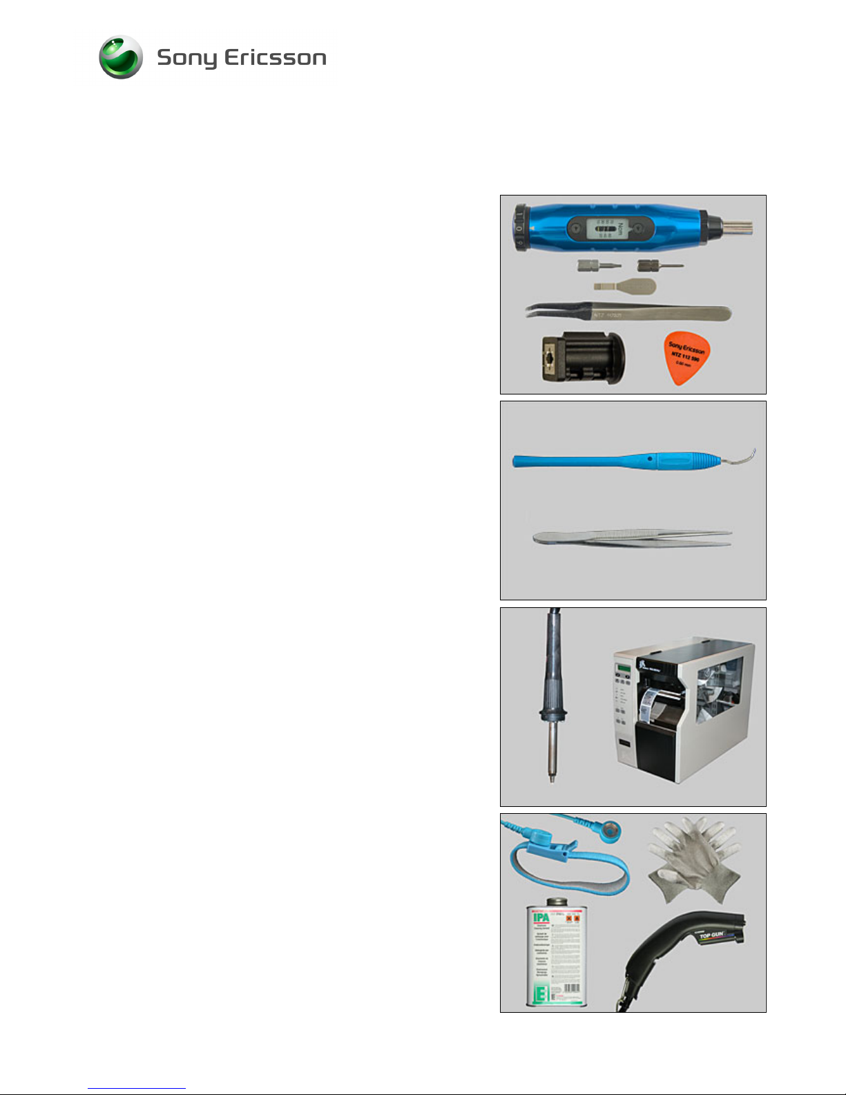
1.2 Equipment
SPECIAL TOOLS
• NTZ 122 459 Torque screwdriver (or equivalent)
• NTZ 122 288 Torx bit no. 6
• NTZ 112 1052 JCIS bit
• NTZ 112 302/2 Front opening tool
• NTZ 122 521 Flex film assembly tool
• LSY 901 55 VGA Camera Removal Tool
• NTZ 112 590 Guitar pick
STANDARD TOOLS
Standard tools have to be locally purchased
• Dentist hook
• ESD tweezers
LABEL EQUIPMENT
The following special equipment is required when replacing
or installing a new label:
• Hot air flow solder station
• Zebra printer connected to computer
OTHER EQUIPMENT
• ESD-wristband
• ESD-gloves
• Isopropyl alcohol
• Air blower
Page 5

Working Instruction, Mechanical
3/000 21-1/FEA 209 544/134 E
Company Internal
© Sony Ericsson Mobile Communications AB
5(69)
1.3 General cautions
The following cautions are considered to be generic for all phone models and will not be repeated in
the Disassembly, Replacements and Reassembly sections:
• T
URN OFF THE PHONE AND REMOVE THE SIM CARD AND THE MEMORY CARD BEFORE STARTING THE
DISASSEMBLY!
•
KEEP ALL CONTACT SURFACES CLEAN!
•
BE CAREFUL WHEN USING TOOLS LIKE THE DENTIST HOOK, TWEEZERS, OPENING TOOLS, GUITAR PICK
ETC. TO AVOID SCRATCHES OR DAMAGES TO THE EXTERIOR AND INTERIOR PARTS OF THE PHONE!
•
BE CAREFUL NOT TO DAMAGE ANY CONTACT SPRINGS!
•
REMEMBER TO REMOVE THE PROTECTION FOILS ON NEW PARTS SUCH AS THE LCD!
•
NEVER TOUCH THE DISPLAY GLASS!
•
USE AIR BLOW EQUIPMENT TO KEEP THE FRONT WINDOW AND DISPLAY MODULE DUST FREE!
1.4 Discharge Camera Flash before Disassembly
Before performing any disassembly, discharge the camera flash by performing the following steps.
1) Close the lens cover
2) Install a battery
3) Power the phone on and go to the Service Test Menu
4) Select the "Discharge Flash" option
5) Wait several seconds until the strobe light flashes
6) Power the phone down
If it is not possible to access the Service Test Menu, leave the unit without battery for 30
minutes and the camera flash will be discharged.
NOTE! The phone may still contain residual voltage that can discharge through
skin contact, but it is not enough to cause injury. This discharge may be avoided by wearing
rubber glover.
Page 6
Working Instruction, Mechanical
3/000 21-1/FEA 209 544/134 E
Company Internal
© Sony Ericsson Mobile Communications AB
6(69)
2 Disassembly
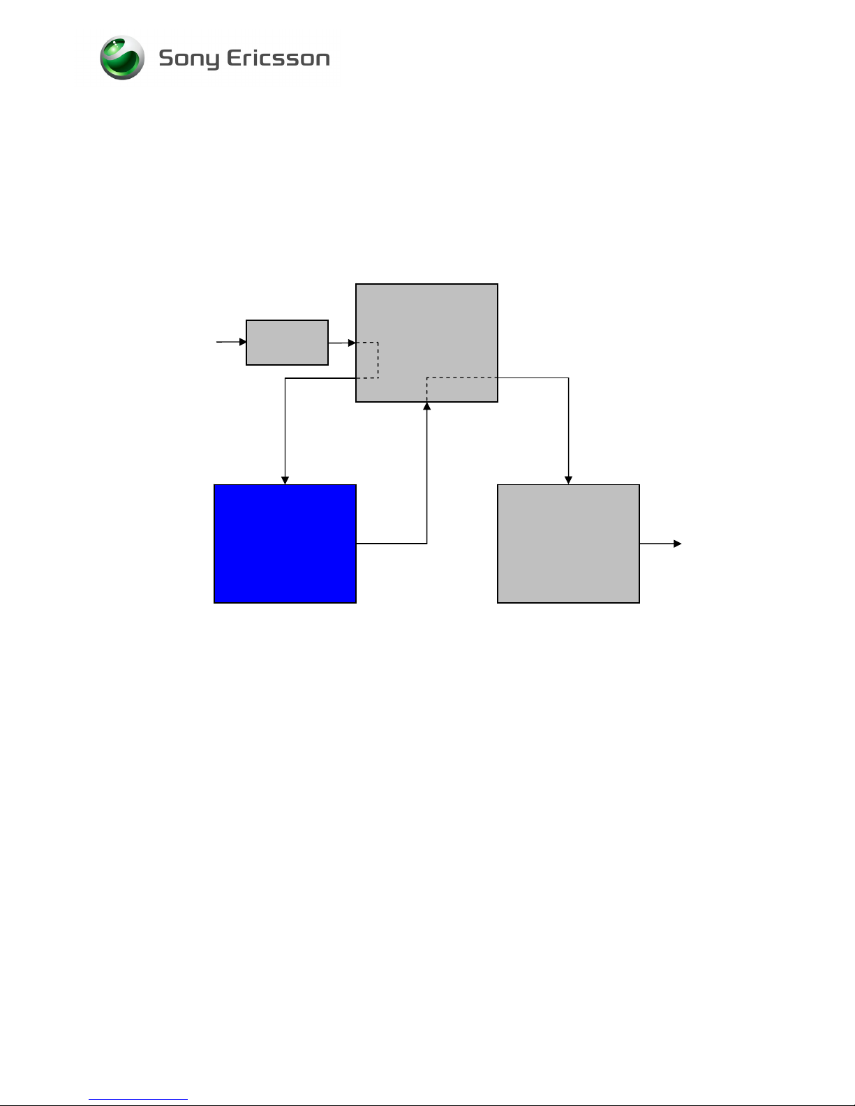
When you are going to replace a part being listed in Replacements, the instruction of that section
usually begins by directing you to this Disassembly section with a specification of the instructions you
have to carry out in order to disassemble the phone as far as needed before returning to
Replacements for the actual replacement.
Start
Done
REPLACEMENTS
DISASSEMBLY
REASSEMBLY
Contents
page
Page 7
Working Instruction, Mechanical
3/000 21-1/FEA 209 544/134 E
Company Internal
© Sony Ericsson Mobile Communications AB
7(69)
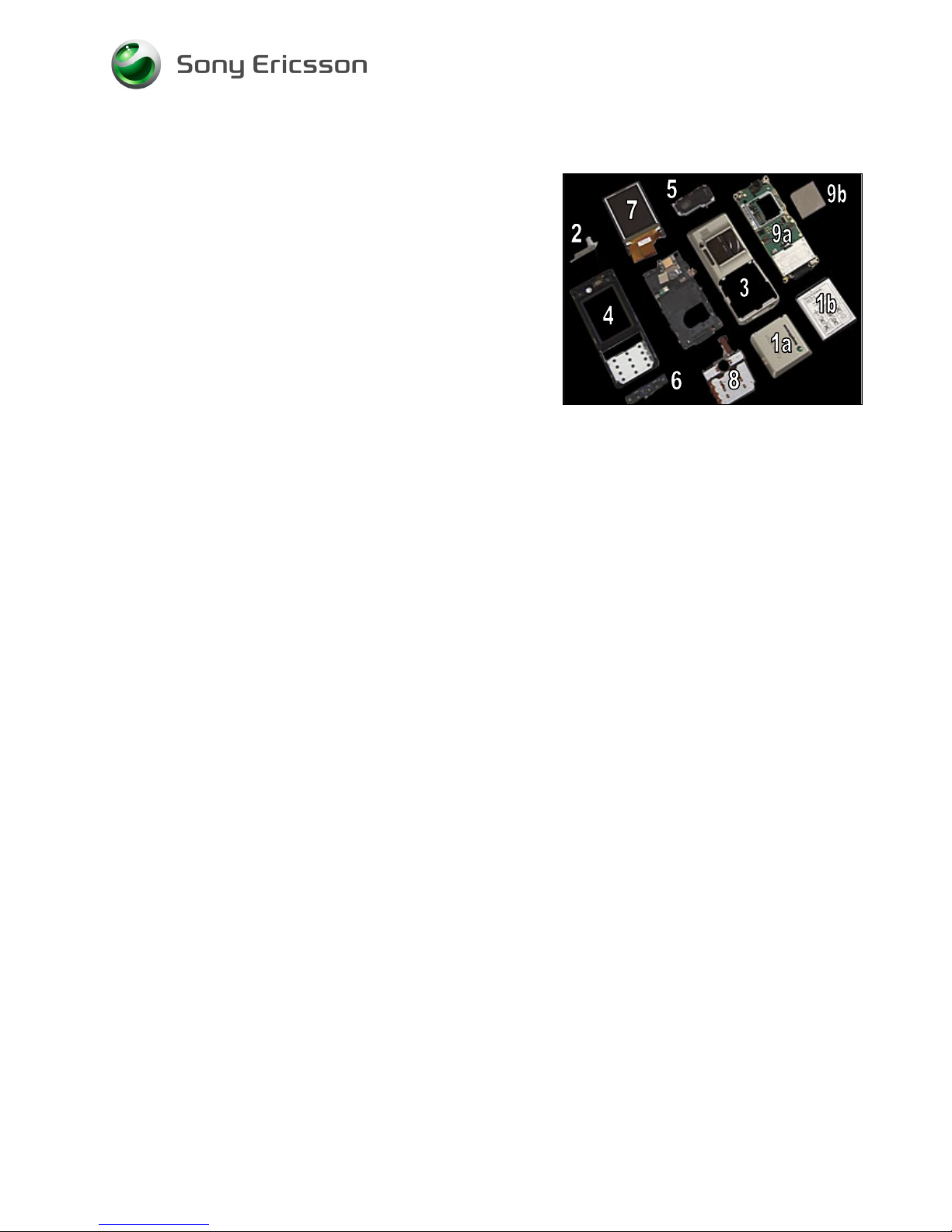
2.1 Overview
The disassembly is done in the following order:
1. Battery Lid Assembly (a) & Battery (b)
2. MS Cover
3. Antenna Cover Assembly
4. Front
5. Antenna/Speaker Box Assembly
6. Function Keyboard Assy
7. LCD
8. Key Foil Complete
9. PCB (a) & Shield Can Lid, Camera Assy (b)
Page 8
Working Instruction, Mechanical
3/000 21-1/FEA 209 544/134 E
Company Internal
© Sony Ericsson Mobile Communications AB
8(69)
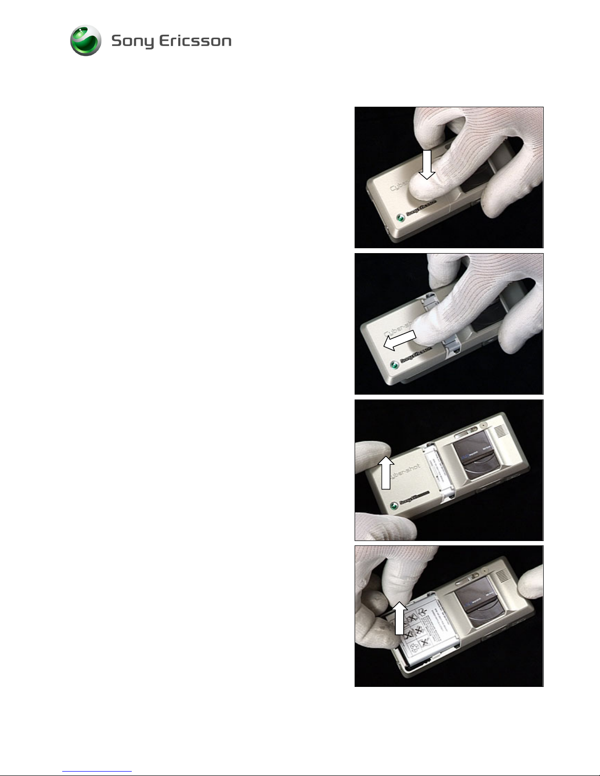
2.1.1 Battery Lid Assembly & Battery
Release the Battery Cover.
Slide the battery cover from the phone.
Remove the Battery Cover.
Grab the Battery and pull it up.
Page 9
Working Instruction, Mechanical
3/000 21-1/FEA 209 544/134 E
Company Internal
© Sony Ericsson Mobile Communications AB
9(69)
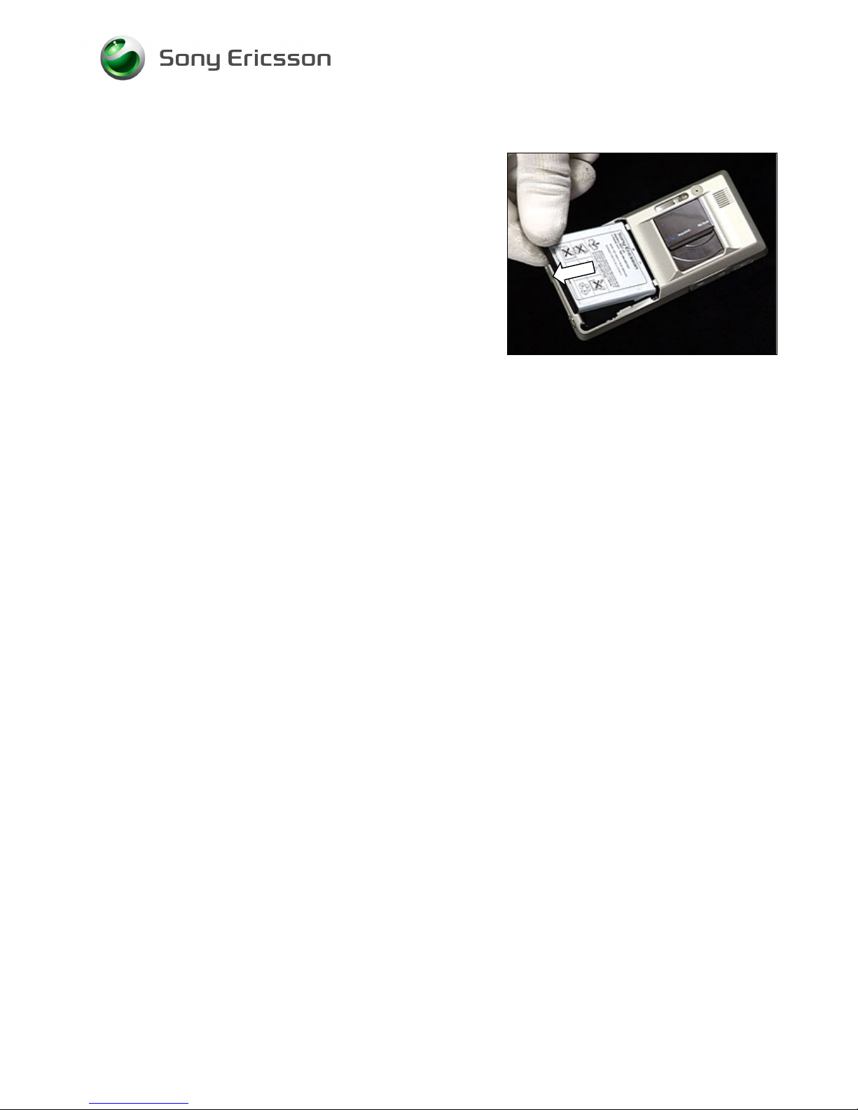
Battery Lid Assembly & Battery continued
Remove the Battery.
Page 10
Working Instruction, Mechanical
3/000 21-1/FEA 209 544/134 E
Company Internal
© Sony Ericsson Mobile Communications AB
10(69)
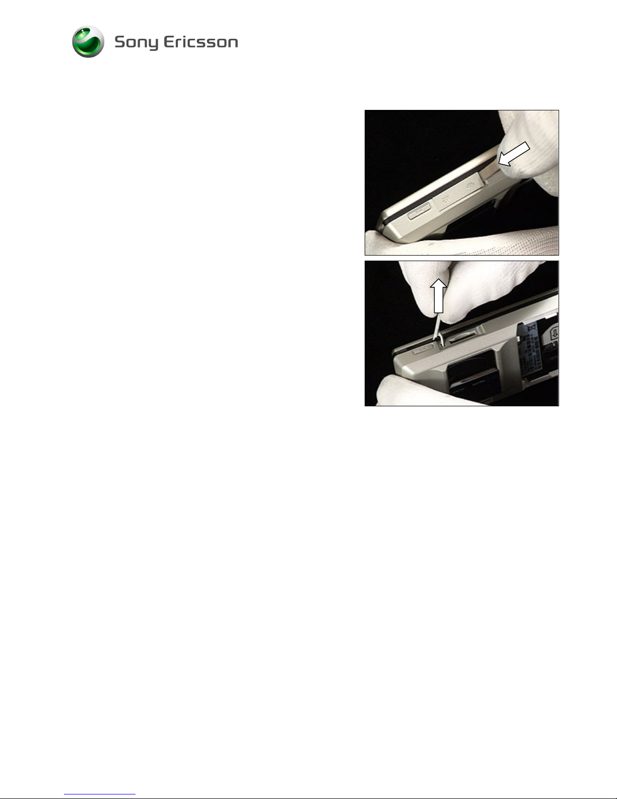
2.1.2 MS Cover
Use a front opening tool to open MS Cover
DO NOT FORGOTT TO REMOVE THE MEMORY CARD!
Remove the MS Cover by pulling out the tab that
connects the cover to the phone.
Page 11
Working Instruction, Mechanical
3/000 21-1/FEA 209 544/134 E
Company Internal
© Sony Ericsson Mobile Communications AB
11(69)
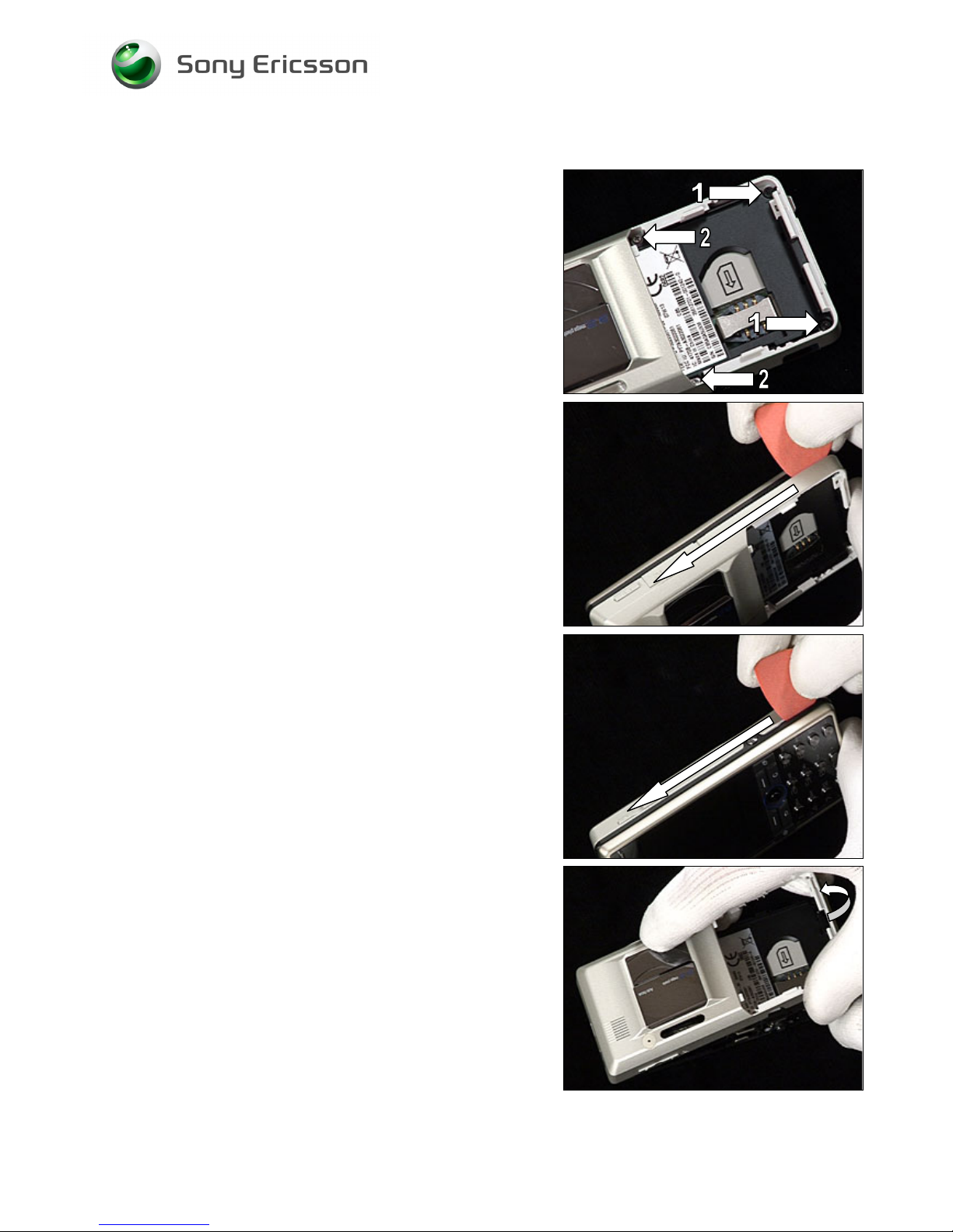
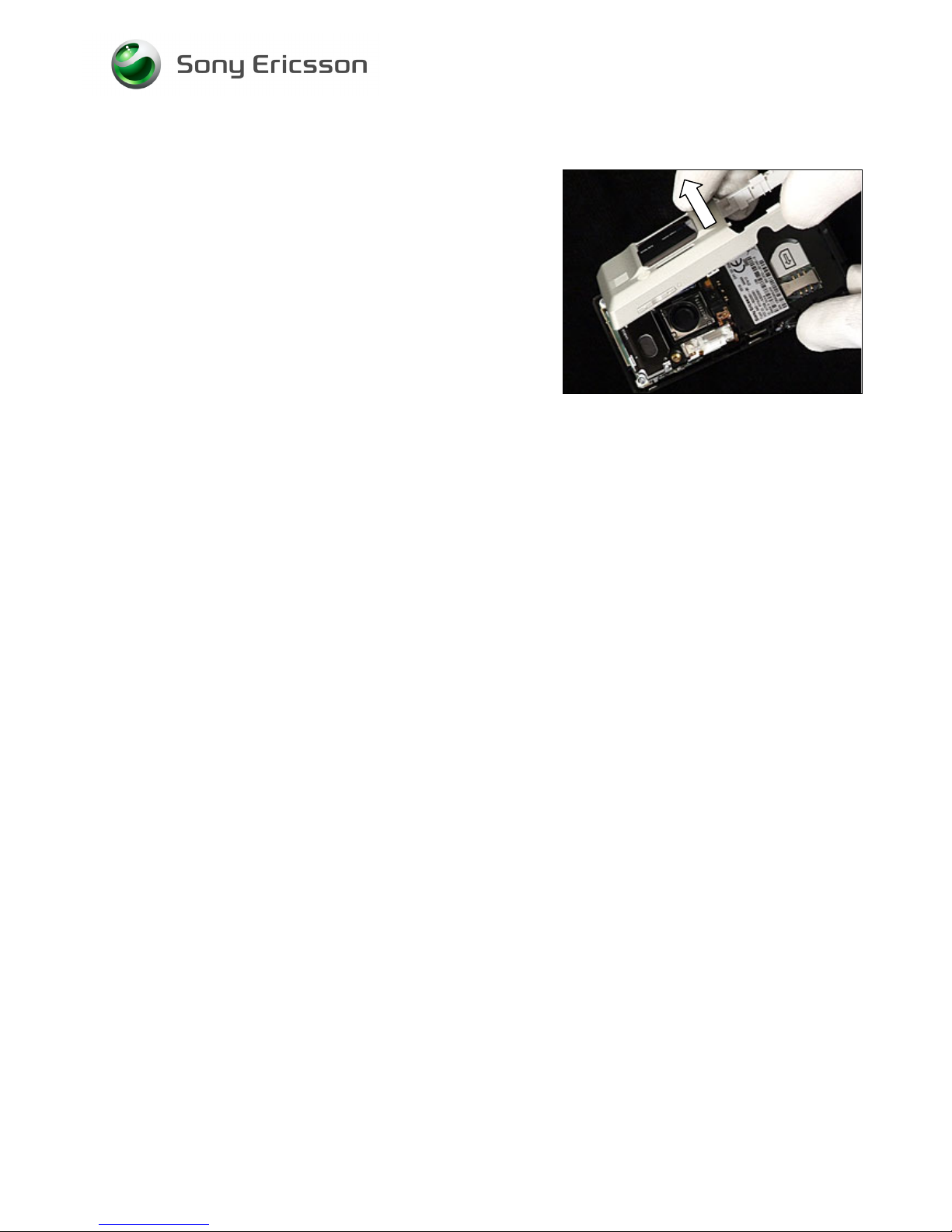
2.1.3 Antenna Cover Assembly
Use Torx bit no 6 to remove the two screws numbered 1.
Use JCIS to remove the two screws numbered 2.
Use a guitar pick and slide upwards and downwards to
release the Front from the Antenna Cover Assembly.
Start on the opposite side and do the same thing.
Use your fingers and wiggle the Antenna Cover Assembly
upwards to release it from the Front.
Page 12
Working Instruction, Mechanical
3/000 21-1/FEA 209 544/134 E
Company Internal
© Sony Ericsson Mobile Communications AB
12(69)
Antenna Cover Assembly continued
Remove the Antenna Cover Assembly.
Page 13
Working Instruction, Mechanical
3/000 21-1/FEA 209 544/134 E
Company Internal
© Sony Ericsson Mobile Communications AB
13(69)
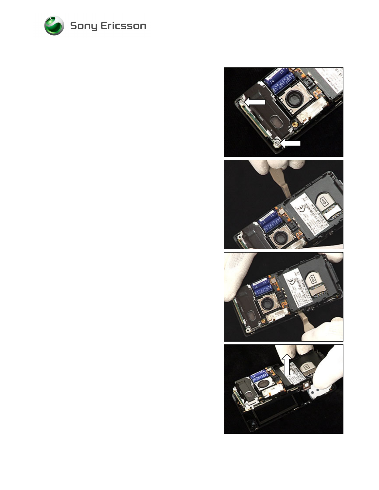
2.1.4 Front Unit
Use Torx bit no 6 to remove the two screws.
Use the front opening tool to bend and make the Front to
start to become loose.
Start on the opposite side and do the same thing.
Gently remove the Core Unit from the Front.
Page 14
Working Instruction, Mechanical
3/000 21-1/FEA 209 544/134 E
Company Internal
© Sony Ericsson Mobile Communications AB
14(69)
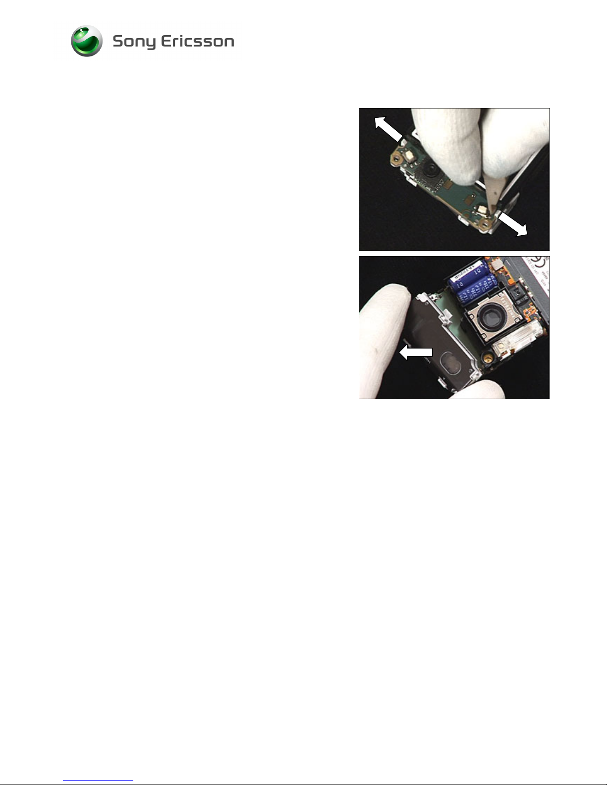
2.1.5 Antenna/Speaker Box Assembly
Use the front opening tool to release the two latches
indicated from the edge of the PBA.
Remove the Antenna/Speaker Box Assembly
Page 15
Working Instruction, Mechanical
3/000 21-1/FEA 209 544/134 E
Company Internal
© Sony Ericsson Mobile Communications AB
15(69)
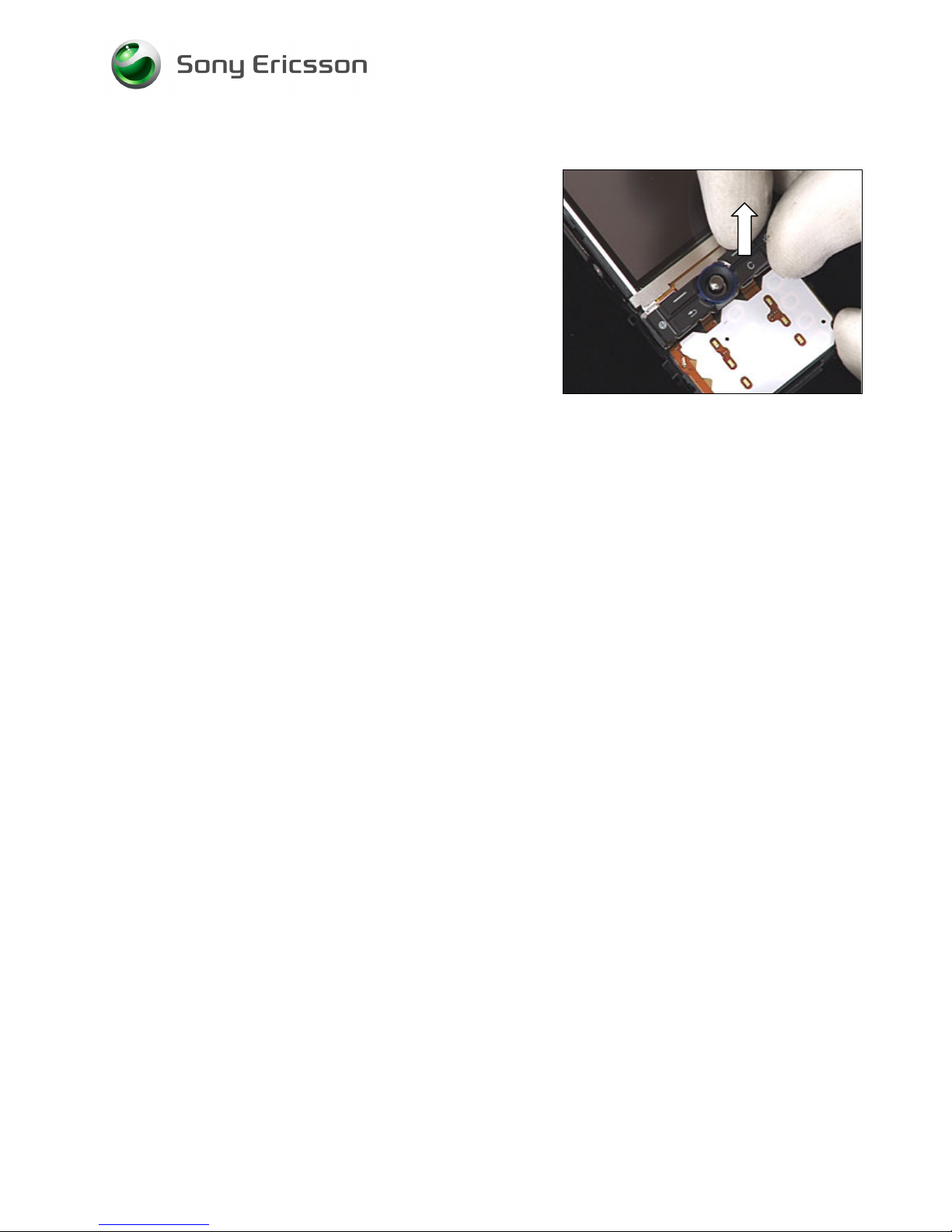
2.1.6 Function Keyboard Assembly
Remove the Function Keyboard Assembly with your fingers.
Page 16
Working Instruction, Mechanical
3/000 21-1/FEA 209 544/134 E
Company Internal
© Sony Ericsson Mobile Communications AB
16(69)
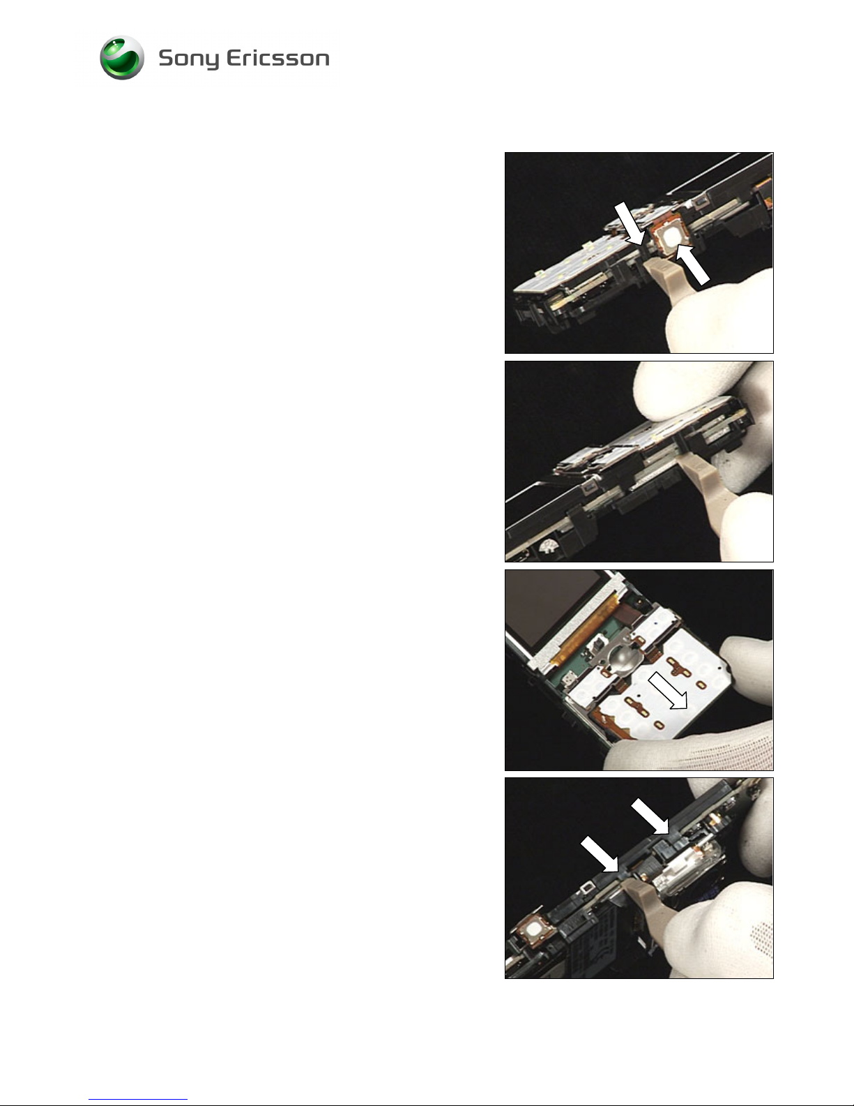
2.1.7 Key Foil Complete/LCD release
Use the front opening tool to release the two latches
indicated.
Do the same thing on the opposite side.
Position the Key Foil Complete over the system connector.
Be careful not to pull on the Key Foil flex film.
Use the front opening tool to release the two latches
indicated on the LCD holder.
Page 17
Working Instruction, Mechanical
3/000 21-1/FEA 209 544/134 E
Company Internal
© Sony Ericsson Mobile Communications AB
17(69)
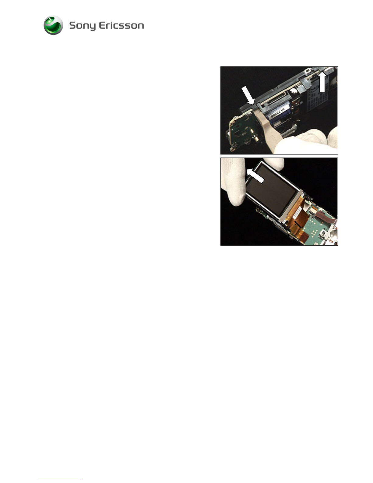
Key Foil & LCD release continued
Do the same thing on the opposite side.
Position the LCD over the end of the phone.
Be careful not to pull on the LCD flex film.
Page 18
Working Instruction, Mechanical
3/000 21-1/FEA 209 544/134 E
Company Internal
© Sony Ericsson Mobile Communications AB
18(69)
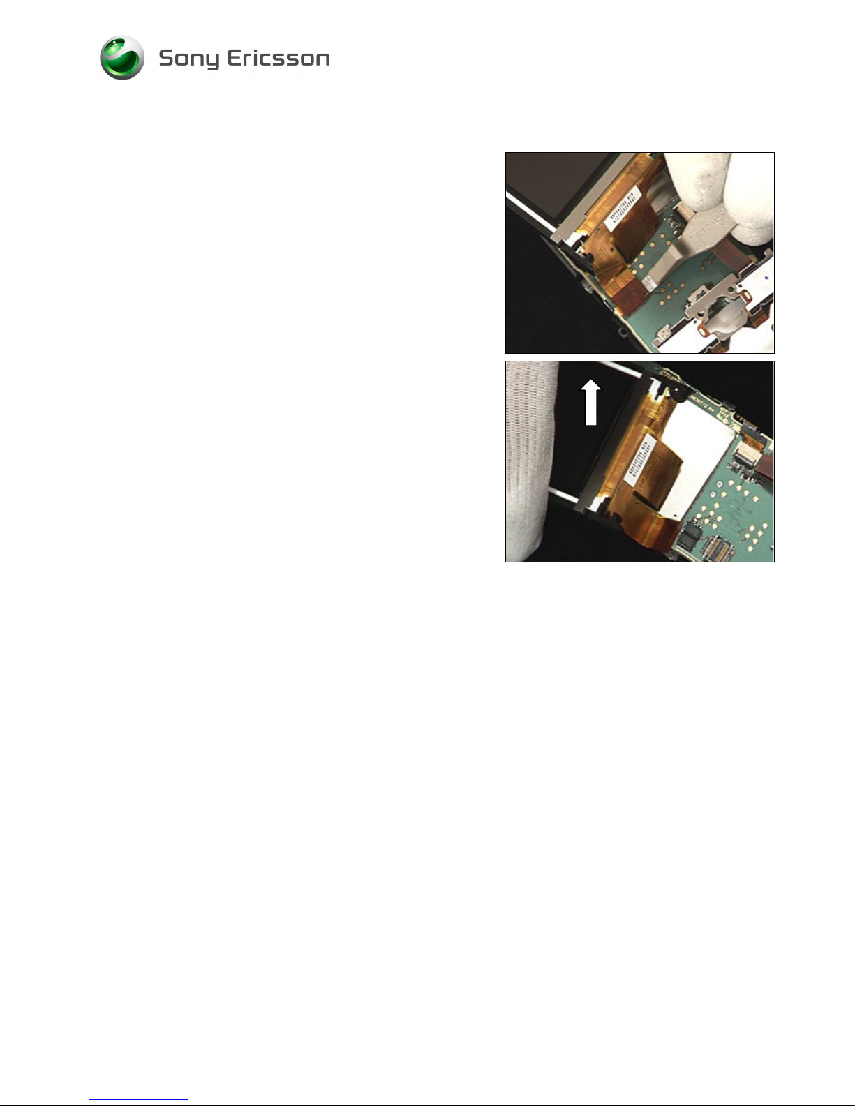
2.1.8 LCD
Use a front opening tool and pull it upwards to disconnect
the LCD from the BtB connector.
Remove the LCD from the PBA.
Page 19
Working Instruction, Mechanical
3/000 21-1/FEA 209 544/134 E
Company Internal
© Sony Ericsson Mobile Communications AB
19(69)
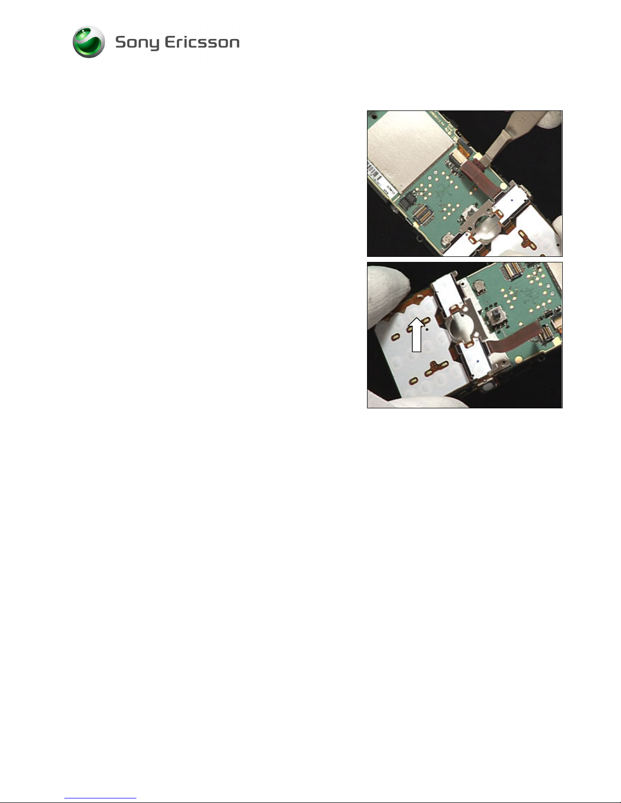
2.1.9 Key Foil Complete
Use a front opening tool and pull it upwards to disconnect
the Key Foil Complete from the BtB connector.
Remove the Key Foil Complete from the PBA.
Page 20
Working Instruction, Mechanical
3/000 21-1/FEA 209 544/134 E
Company Internal
© Sony Ericsson Mobile Communications AB
20(69)
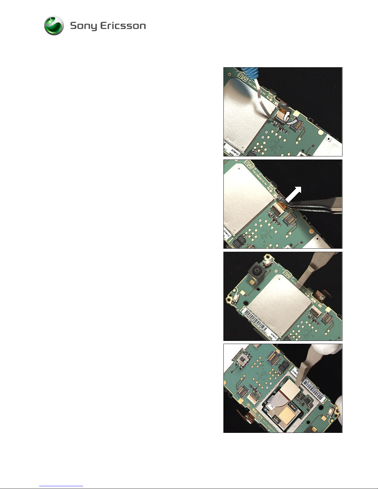
2.1.10 PCB & Shield Can Lid, Camera Assy
Rotate the black retaining bar of the connector toward
the flex film.
Use a flex film assembly tool and pull the flex film from the
connector.
Use the front opening tool to remove the Shield Can,
Camera Assembly.
Be VERY careful when removing the Camera
BtB connector or it might brake!
Use a front opening tool to disconnect the Camera from the
BtB connector.
Page 21
Working Instruction, Mechanical
3/000 21-1/FEA 209 544/134 E
Company Internal
© Sony Ericsson Mobile Communications AB
21(69)
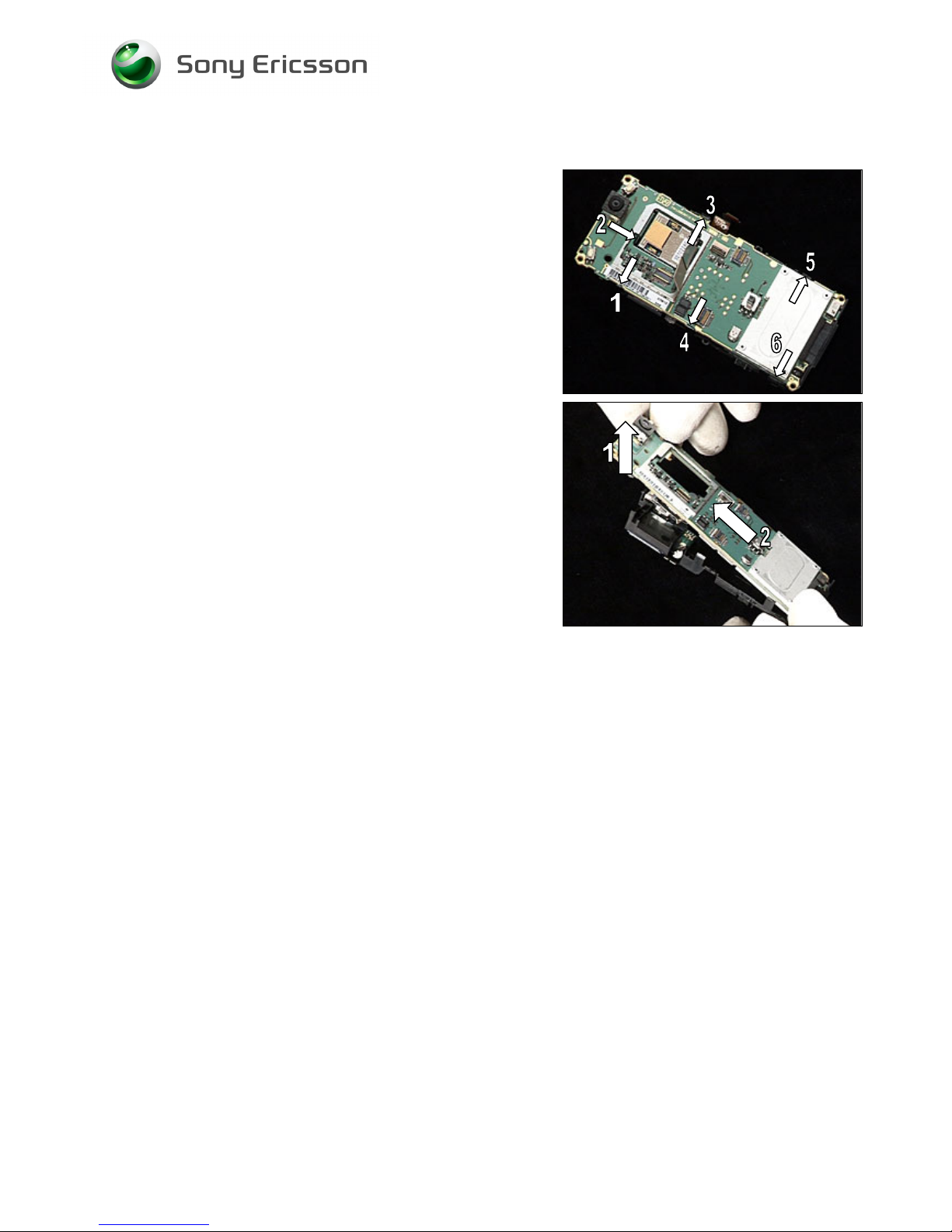
PCB with Shield Can Lid, Camera Assy continued
Use a front opening tool to release the six latches in the
order shown from the edge of the PBA.
First lift up the PBA.
Second pull the PBA out of the Frame assy.
Page 22
Working Instruction, Mechanical
3/000 21-1/FEA 209 544/134 E
Company Internal
© Sony Ericsson Mobile Communications AB
22(69)
3 Replacements
Search for the part to be replaced on the Contents page and go to that instruction to be found in this
Replacements section.
The instruction usually begins by directing you to the Disassembly section with a specification of the
instructions you have to carry out in order to disassemble the phone as far as needed before the
actual replacement.
Go back to this Replacements section and carry out the instruction.
The instruction usually ends by directing you to the Reassembly section with a specification of the
instructions you have to carry out in order to reassemble the phone.
Start
Done
REPLACEMENTS
DISASSEMBLY REASSEMBLY
Contents
page
Page 23

Working Instruction, Mechanical
3/000 21-1/FEA 209 544/134 E
Company Internal
© Sony Ericsson Mobile Communications AB
23(69)
3.1 Battery Lid Assembly
Follow the 2.1.1 Disassembly instructions!
Prepare the new Battery Lid Assembly.
Follow the 4.1.10 Reassembly instructions!
3.2 MS Cover
Follow the 2.1.2 Disassembly instructions!
Prepare the new MS Cover.
Follow the 4.1.9 Reassembly instructions!
3.3 Antenna Cover Assembly
Follow the 2.1.1 – 2.1.3 Disassembly instructions!
Prepare the new Antenna Cover Assembly.
Follow the 4.1.8 – 4.1.10 Reassembly instructions!
3.4 Antenna/Speaker Box Assembly
Follow the 2.1.1 – 2.1.5 Disassembly instructions!
Prepare the new Antenna/Speaker Box Assembly.
Follow the 4.1.6 – 4.1.10 Reassembly instructions!
3.5 Function Keyboard Assy
Follow the 2.1.1 – 2.1.6 Disassembly instructions!
Prepare the new Function Keyboard Assy.
Follow the 4.1.5 – 4.1.10 Reassembly instructions!
3.6 Key Foil Complete
Follow the 2.1.1 – 2.1.9 Disassembly instructions!
Prepare the new Key Foil Complete.
Follow the 4.1.2 – 4.1.10 Reassembly instructions!
3.7 Shield Can Lid, Camera Assy
Follow the 2.1.1 – 2.1.10 Disassembly instructions!
Prepare the new Shield Can Lid, Camera Assy.
Follow the 4.1.1 – 4.1.10 Reassembly instructions!
Page 24

Working Instruction, Mechanical
3/000 21-1/FEA 209 544/134 E
Company Internal
© Sony Ericsson Mobile Communications AB
24(69)
3.8 Frame Assembly
Follow the 2.1.1 – 2.1.10 Disassembly instructions!
Remove the Camera as described in 3.12
Remove the Vibrator as described in 3.13
Remove the Xenon Flash as described in 3.19
Prepare the new Frame Assembly.
Install the old Camera as described in 3.12
Install the old Vibrator as described in 3.13
Install the old Xenon Flash as described in 3.19
Install a new KRH Label as described in 3.33
Follow the 4.1.1 – 4.1.10 Reassembly instructions!
Page 25
Working Instruction, Mechanical
3/000 21-1/FEA 209 544/134 E
Company Internal
© Sony Ericsson Mobile Communications AB
25(69)
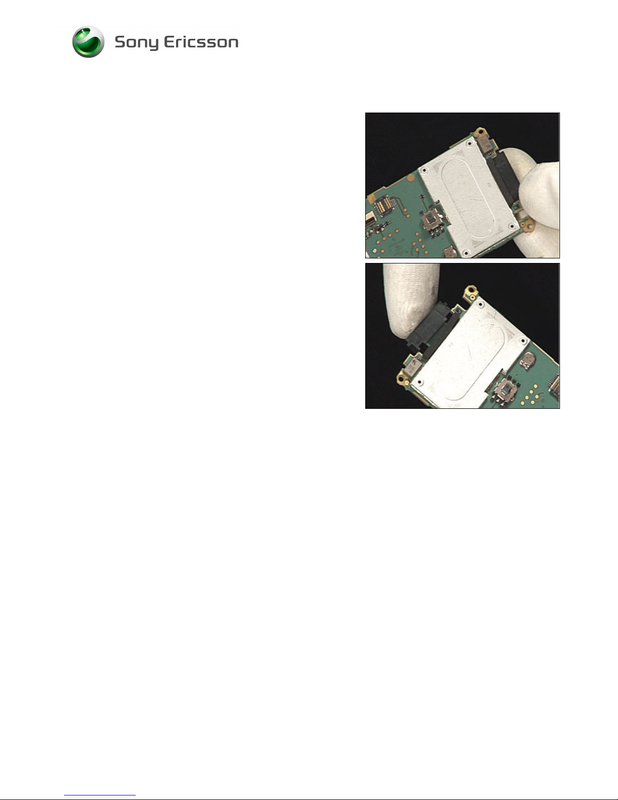
3.9 System Connector
REMOVAL
Follow the 2.1.1 – 2.1.10 Disassembly instructions!
Use your fingers to remove the System Connector.
INSTALLATION
Use your fingers to position the System Connector.
Follow the 4.1.1 – 4.1.10 Reassembly instructions!
Page 26
Working Instruction, Mechanical
3/000 21-1/FEA 209 544/134 E
Company Internal
© Sony Ericsson Mobile Communications AB
26(69)
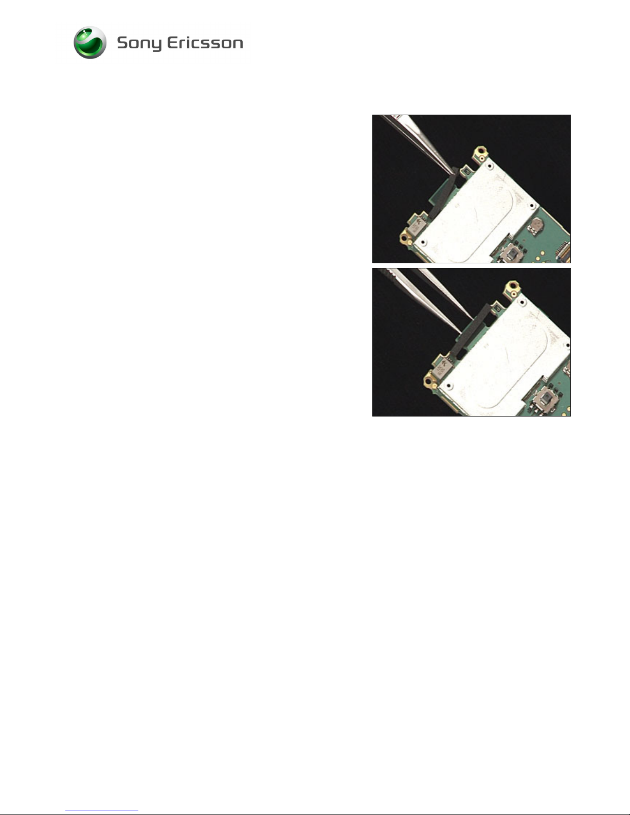
3.10 Dust Gasket for System Connector
REMOVAL
Follow the 2.1.1 – 2.1.10 Disassembly instructions!
Follow the 3.8 Removal instructions!
Use tweezers to remove the Dust Gasket, System
Connector.
INSTALLATION
Use tweezers to position the Dust Gasket, System
Connector.
Follow the 3.8 Installation instructions!
Follow the 4.1.1 – 4.1.10 Reassembly instructions!
Page 27
Working Instruction, Mechanical
3/000 21-1/FEA 209 544/134 E
Company Internal
© Sony Ericsson Mobile Communications AB
27(69)
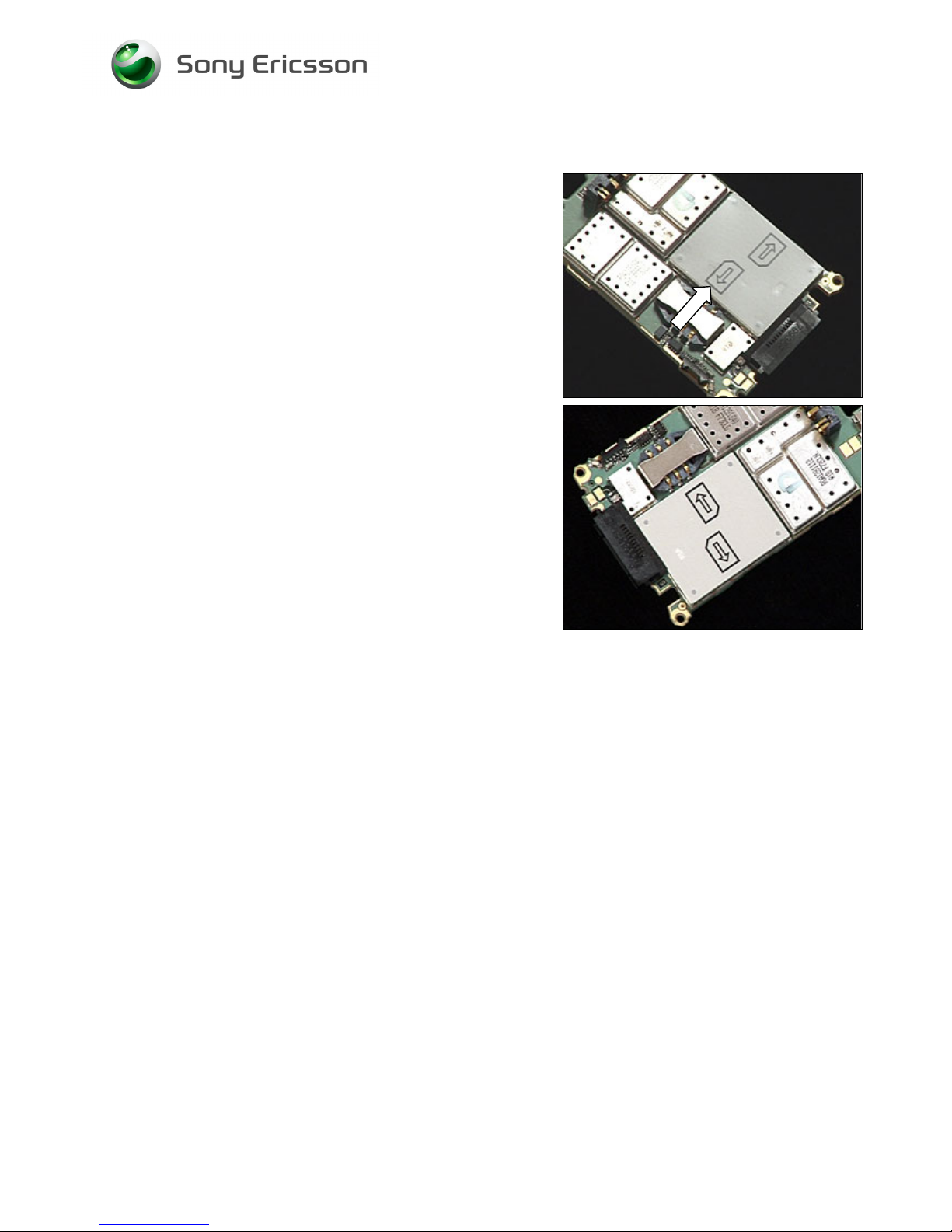
3.11 Insulation Label
REMOVAL
Follow the 2.1.1 – 2.1.10 Disassembly instructions!
Use tweezers to remove the Insulation label.
INSTALLATION
Use tweezers to position the Insulation label.
Follow the 4.1.1 – 4.1.10 Reassembly instructions!
Page 28
Working Instruction, Mechanical
3/000 21-1/FEA 209 544/134 E
Company Internal
© Sony Ericsson Mobile Communications AB
28(69)
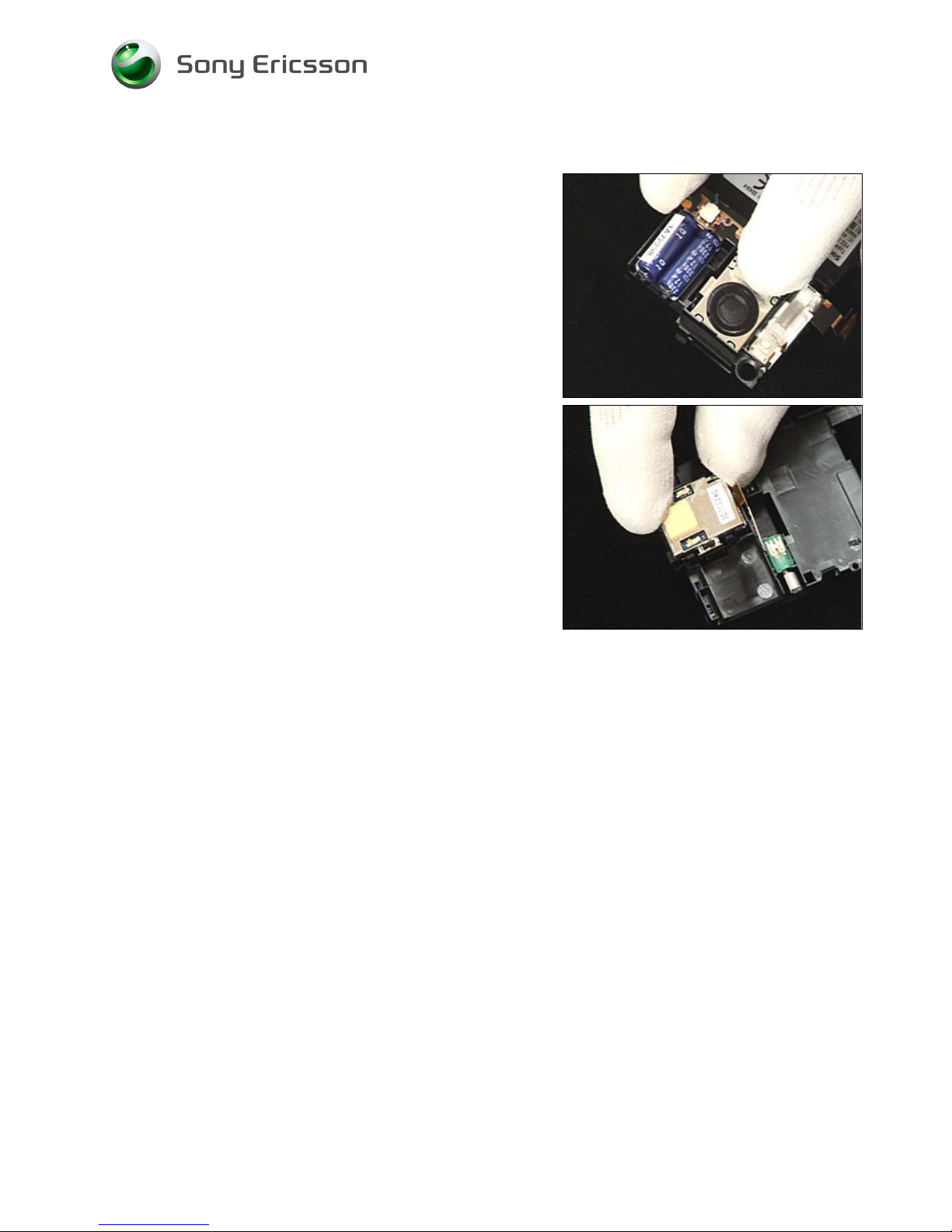
3.12 Camera
REMOVAL
Follow the 2.1.1 – 2.1.10 Disassembly instructions!
Push on the lens side of the camera so that the Camera
falls out of its cavity in the Frame assy.
INSTALLATION
Use your fingers to position the Camera.
Follow the 4.1.1 – 4.1.10 Reassembly instructions!
Page 29
Working Instruction, Mechanical
3/000 21-1/FEA 209 544/134 E
Company Internal
© Sony Ericsson Mobile Communications AB
29(69)
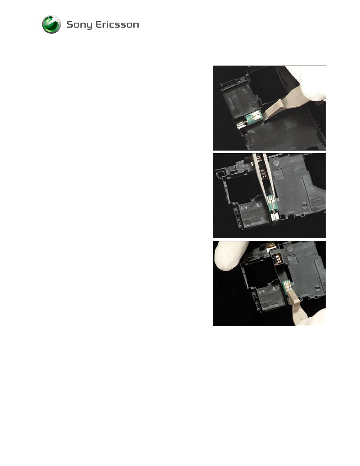
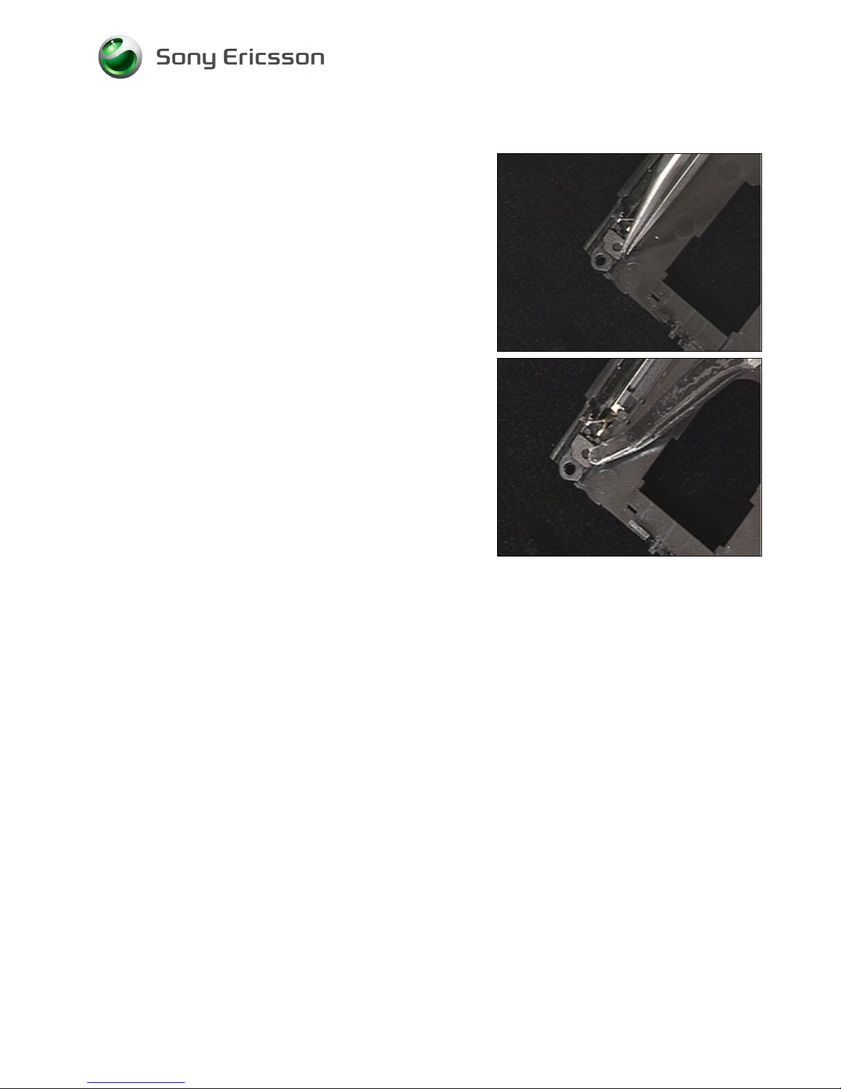
3.13 Vibrator
REMOVAL
Follow the 2.1.1 – 2.1.10 Disassembly instructions!
Use a front opening tool to lift up the Vibrator.
Use tweezers to remove the Vibrator
INSTALLATION
DO NOT TOUCH THE VIBRATOR SPRINGS!
Use a front opening tool to press the Vibrator into its cavity.
Follow the 4.1.1 – 4.1.10 Reassembly instructions!
Page 30
Working Instruction, Mechanical
3/000 21-1/FEA 209 544/134 E
Company Internal
© Sony Ericsson Mobile Communications AB
30(69)
3.14 Microphone Gasket
REMOVAL
Follow the 2.1.1 – 2.1.10 Disassembly instructions!
Use tweezers to remove the Microphone Gasket.
INSTALLATION
Use tweezers to position the Microphone Gasket.
Follow the 4.1.1 – 4.1.10 Reassembly instructions!
Page 31
Working Instruction, Mechanical
3/000 21-1/FEA 209 544/134 E
Company Internal
© Sony Ericsson Mobile Communications AB
31(69)
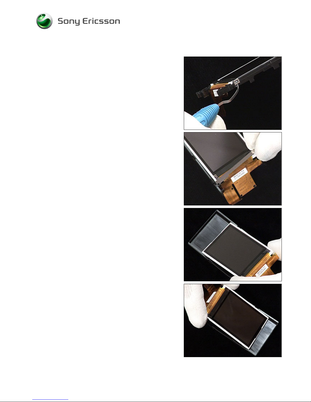
3.15 LCD, LCD Holder Assembly & ESD Protection sheet
REMOVAL
Follow the 2.1.1 – 2.1.8 Disassembly instructions!
Use a dentist hook to unhook the ESD protection sheet.
Use your fingers to remove the ESD protection sheet.
Use your fingers to remove the LCD from the LCD holder
assembly.
INSTALLATION
Use your fingers to position the LCD in the LCD holder
assembly
Page 32
Working Instruction, Mechanical
3/000 21-1/FEA 209 544/134 E
Company Internal
© Sony Ericsson Mobile Communications AB
32(69)
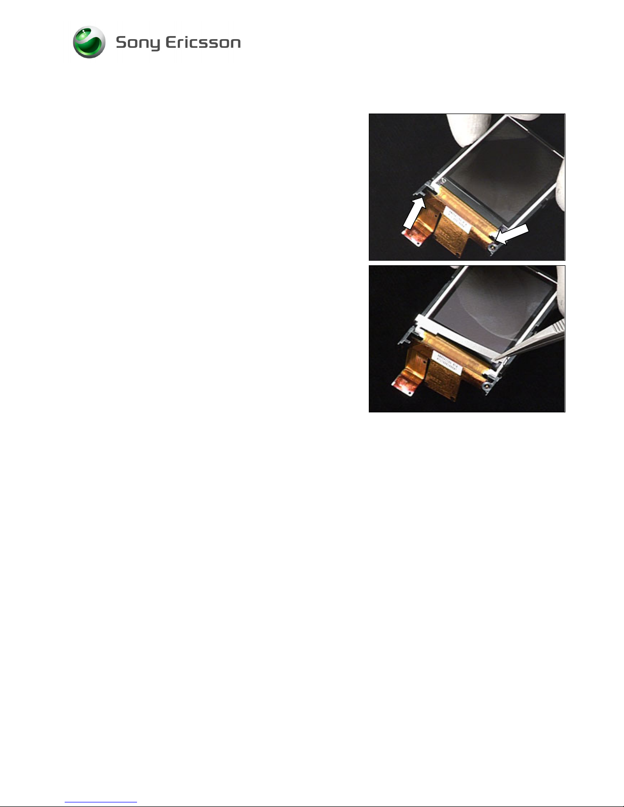
LCD, LCD Holder & ESD Protection sheet continued
Position the LCD flex film behind the two portions of the
LCD holder as shown.
Use tweezers to position the ESD Protection sheet.
Follow the 4.1.3 – 4.1.10 Reassembly instructions!
Page 33
Working Instruction, Mechanical
3/000 21-1/FEA 209 544/134 E
Company Internal
© Sony Ericsson Mobile Communications AB
33(69)
3.16 VGA Socket Gasket – K810 Only
REMOVAL
Follow the 2.1.1 – 2.1.8 Disassembly instructions!
Use tweezers to remove the VGA Socket Gasket
INSTALLATION
Use tweezers to position the VGA Socket Gasket.
Follow the 4.1.3 – 4.1.10 Reassembly instructions!
Page 34
Working Instruction, Mechanical
3/000 21-1/FEA 209 544/134 E
Company Internal
© Sony Ericsson Mobile Communications AB
34(69)
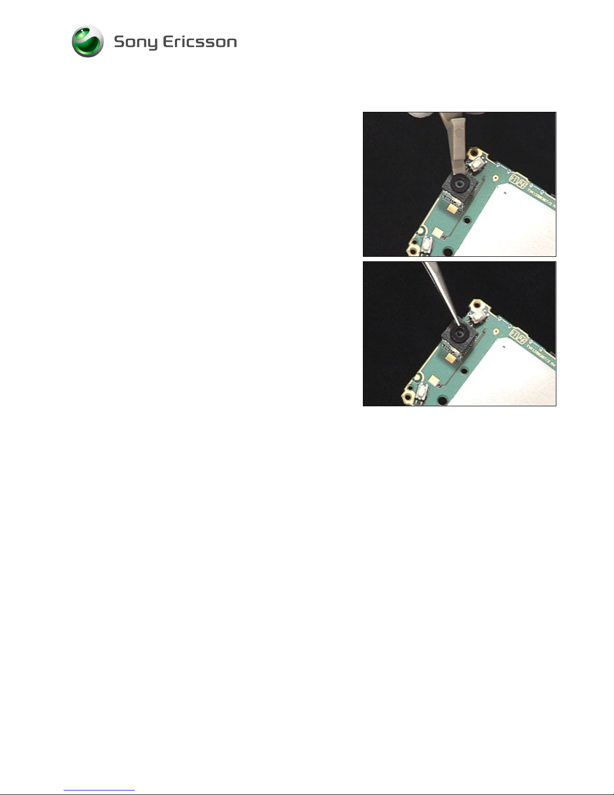
3.17 VGA Camera Window – K810 Only
REMOVAL
Follow the 2.1.1 – 2.1.8 Disassembly instructions!
Use a front opening tool to remove the VGA Camera
Window.
INSTALLATION
Use tweezers to position the VGA Camera Window
Follow the 4.1.3 – 4.1.10 Reassembly instructions!
Page 35
Working Instruction, Mechanical
3/000 21-1/FEA 209 544/134 E
Company Internal
© Sony Ericsson Mobile Communications AB
35(69)
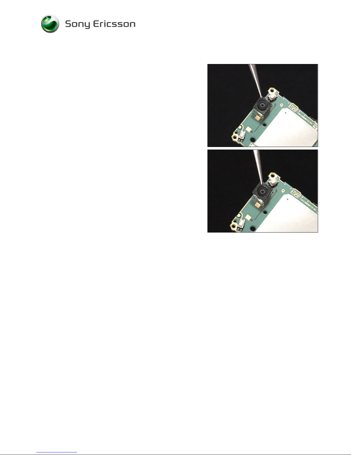
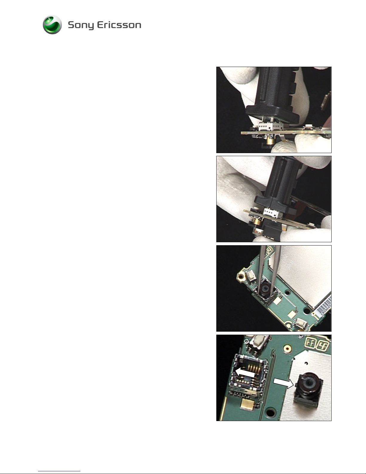
3.18 VGA Camera – K810 Only
REMOVAL
Follow the 2.1.1 – 2.1.8 Disassembly instructions!
Follow the 3.16 – 3.17 Removal instructions!
Use VGA camera removal tool to remove VGA Camera.
Push the VGA camera tool to bottom and wiggle the tool
side to side before lifting the tool up.
Use tweezers to remove the VGA camera
INSTALLATION
Notice the small slot in the socket and the small slot in the
VGA camera.
Page 36
Working Instruction, Mechanical
3/000 21-1/FEA 209 544/134 E
Company Internal
© Sony Ericsson Mobile Communications AB
36(69)
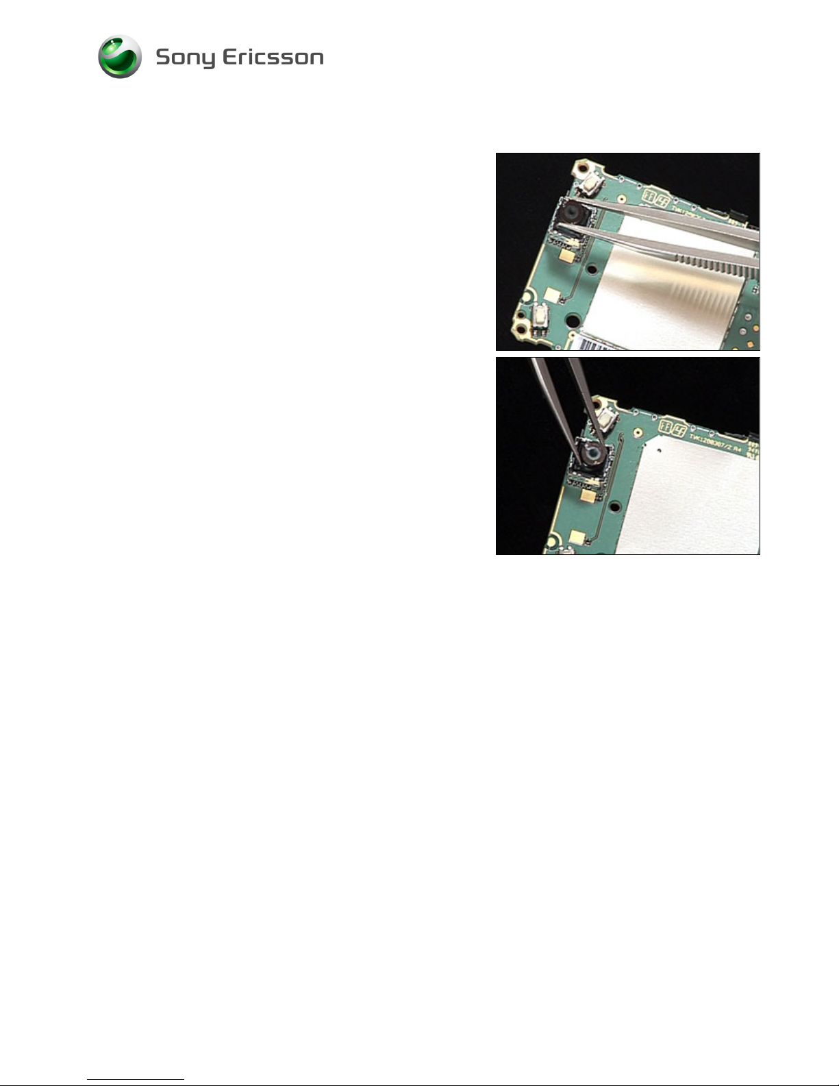
VGA Camera continued
Use tweezers to position the VGA camera
Press gently on the top of the VGA camera until it
snaps into place.
Follow the 3.17 – 3.16 Removal instructions!
Follow the 4.1.3 – 4.1.10 Reassembly instructions!
Page 37
Working Instruction, Mechanical
3/000 21-1/FEA 209 544/134 E
Company Internal
© Sony Ericsson Mobile Communications AB
37(69)
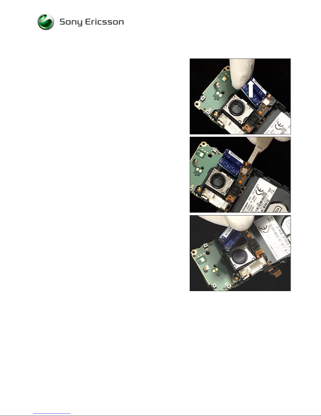
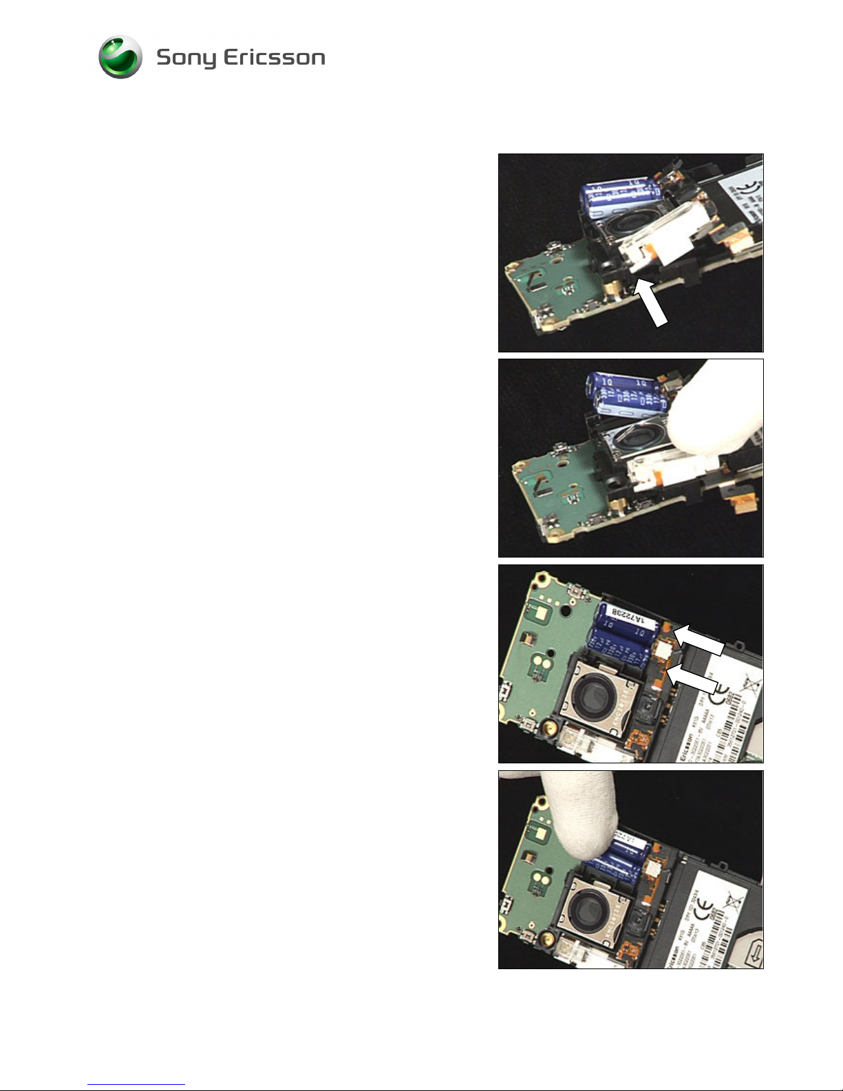
3.19 Xenon Flash
REMOVAL
Follow the 2.1.1 – 2.1.5 Disassembly instructions!
Use your finger to lift the end of both capacitors out of their
cavity.
Use a front opening tool to detach the Xenon flash flex film
from the Frame assembly.
Use your fingers to remove the Xenon flash.
Page 38
Working Instruction, Mechanical
3/000 21-1/FEA 209 544/134 E
Company Internal
© Sony Ericsson Mobile Communications AB
38(69)
Xenon Flash continued
INSTALLATION
Obtain a new Xenon flash and orient it to its cavity in the
Frame assy.
Verify that the Xenon flash goes under the placement peg.
Place the Xenon flash to the frame so that it fits the two
guiding pins.
Use your fingers to snap the capacitors in their cavity in the
frame assy.
Follow the 4.1.6 – 4.1.10 Reassembly instructions!
Page 39
Working Instruction, Mechanical
3/000 21-1/FEA 209 544/134 E
Company Internal
© Sony Ericsson Mobile Communications AB
39(69)
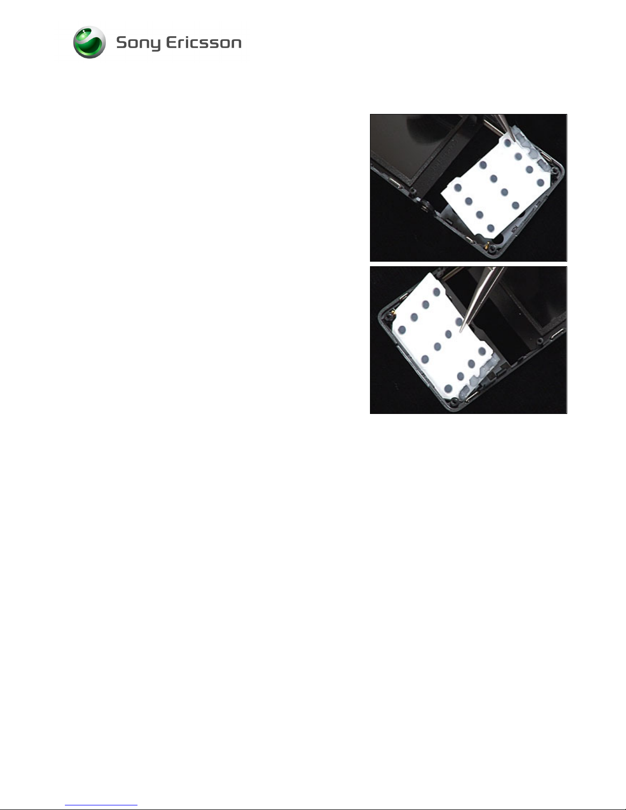
3.20 Numeric Keyboard
REMOVAL
Follow the 2.1.1 – 2.1.4 Disassembly instructions!
Use tweezers to remove the Numeric keyboard.
INSTALLATION
Use tweezers to position the Numeric keyboard.
Follow the 4.1.7 – 4.1.10 Reassembly instructions!
Page 40
Working Instruction, Mechanical
3/000 21-1/FEA 209 544/134 E
Company Internal
© Sony Ericsson Mobile Communications AB
40(69)
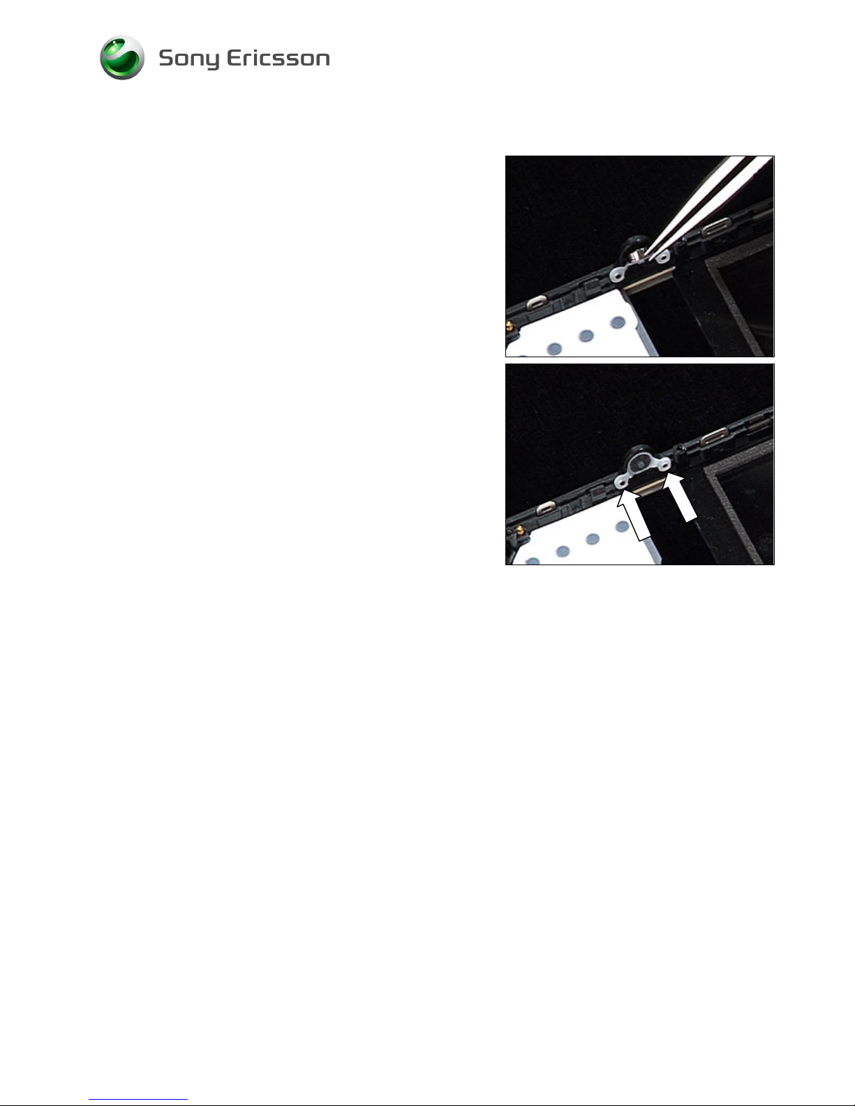
3.21 Camera Key
REMOVAL
Follow the 2.1.1 – 2.1.4 Disassembly instructions!
Use tweezers to remove the Camera key.
INSTALL
Use tweezers to position the Camera key. Use the two
guiding pins.
Follow the 4.1.7 – 4.1.10 Reassembly instructions!
Page 41
Working Instruction, Mechanical
3/000 21-1/FEA 209 544/134 E
Company Internal
© Sony Ericsson Mobile Communications AB
41(69)
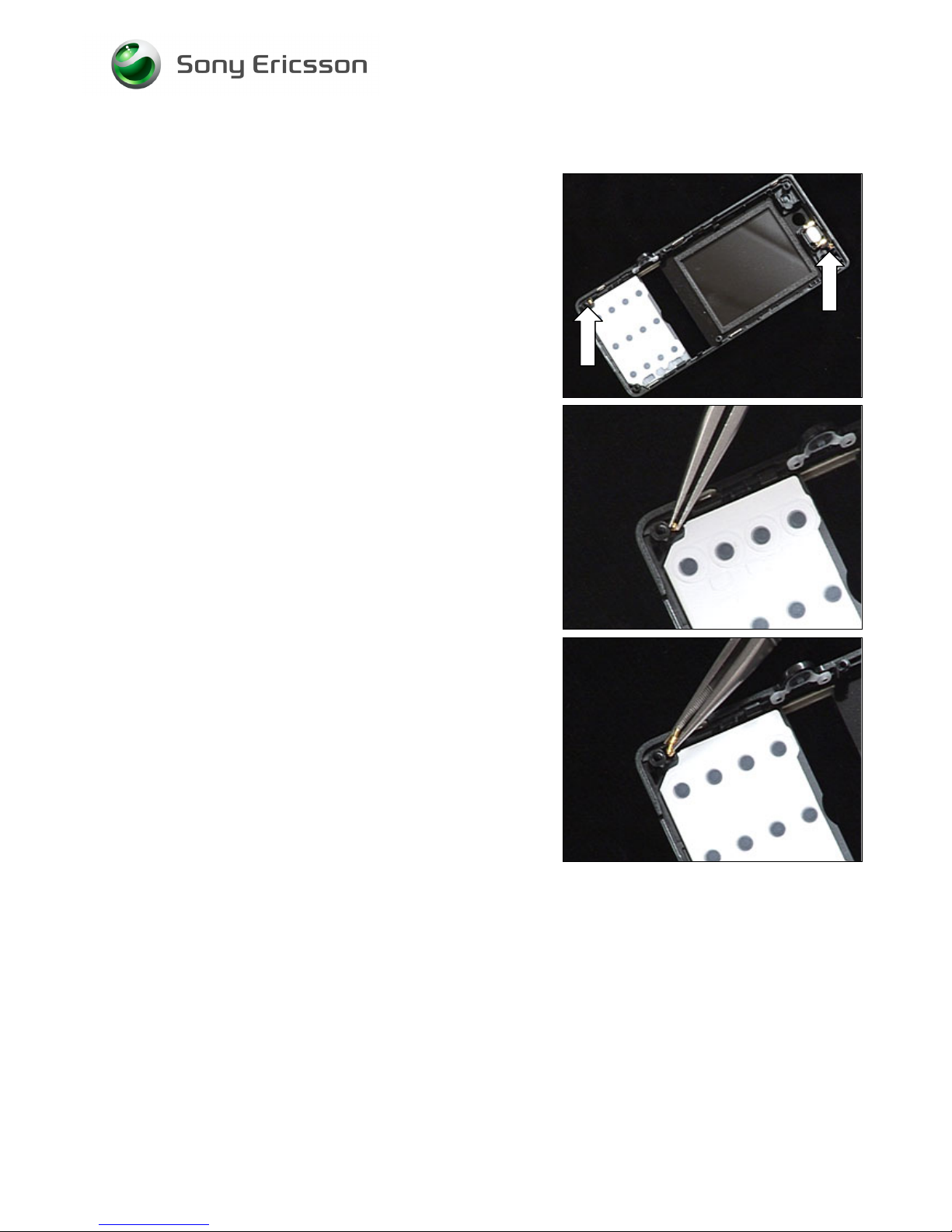
3.22 Ground Connectors
REMOVAL
Follow the 2.1.1 – 2.1.4 Disassembly instructions!
There is two Ground Connectors.
Use tweezers to remove the Ground connector
INSTALLATION
Use tweezers to position the Ground connector
Follow the 4.1.7 – 4.1.10 Reassembly instructions!
Page 42
Working Instruction, Mechanical
3/000 21-1/FEA 209 544/134 E
Company Internal
© Sony Ericsson Mobile Communications AB
42(69)
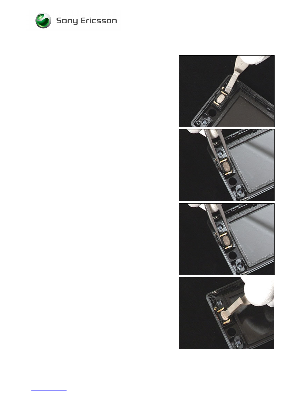
3.23 Ear Speaker
REMOVAL
Follow the 2.1.1 – 2.1.4 Disassembly instructions!
Use a front opening tool to release the Ear speaker.
Use tweezers to remove the Ear speaker.
INSTALLATION
Use tweezers to position the Ear speaker.
DO NOT TOUCH THE EAR SPEAKER SPRINGS!
Use a front opening tool to press the Ear speaker into its
cavity.
Follow the 4.1.7 – 4.1.10 Reassembly instructions!
Page 43
Working Instruction, Mechanical
3/000 21-1/FEA 209 544/134 E
Company Internal
© Sony Ericsson Mobile Communications AB
43(69)
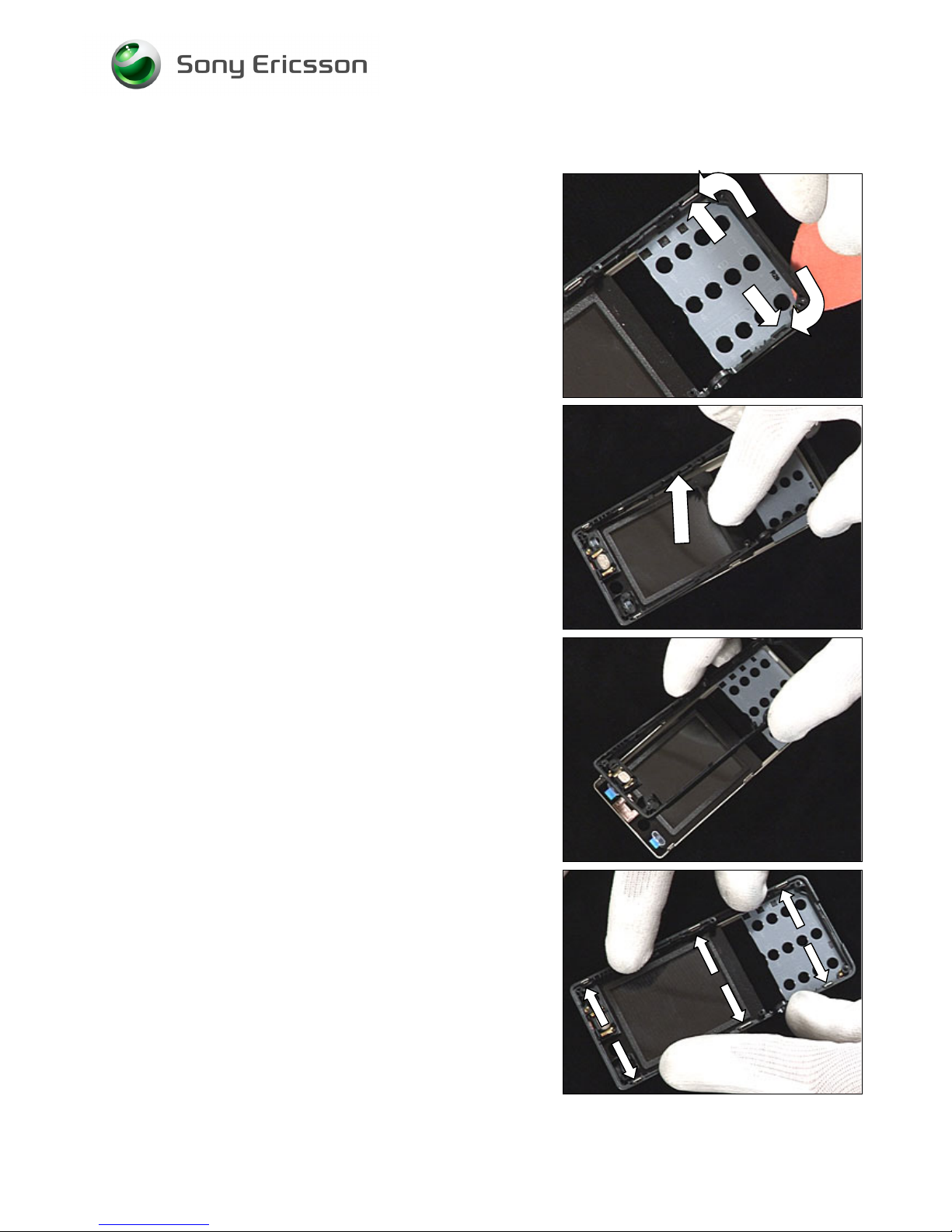
3.24 Front Assy
REMOVAL
Follow the 2.1.1 – 2.1.4 Disassembly instructions!
Use a Guitar pick to unsnap the two first hooks.
Use your fingers and pull the Front assy upwards to release
it from the Front complete.
INSTALLATION
Put the Front assy over the Front complete.
Press down the Front assy with your fingers so that the six
hooks snaps.
Follow the 4.1.7 – 4.1.10 Reassembly instructions!
Page 44
Working Instruction, Mechanical
3/000 21-1/FEA 209 544/134 E
Company Internal
© Sony Ericsson Mobile Communications AB
44(69)
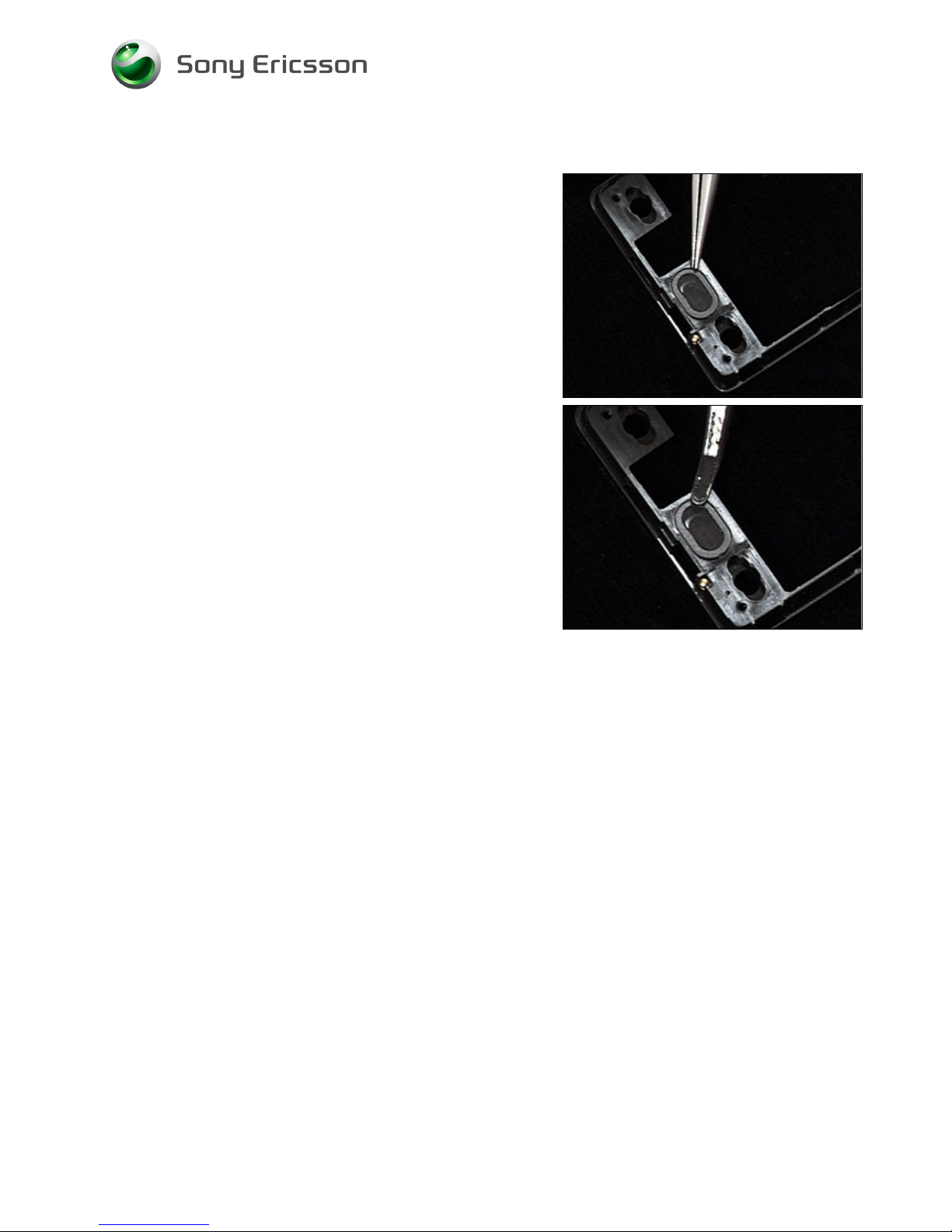
3.25 Ear Speaker Gasket
REMOVAL
Follow the 2.1.1 – 2.1.4 Disassembly instructions!
Follow the 3.24 Removal instructions!
Use tweezers to remove the Ear speaker gasket.
INSTALLATION
Use tweezers to position the Ear speaker gasket.
Follow the 3.24 Installation instructions!
Follow the 4.1.7 – 4.1.10 Reassembly instructions!
Page 45
Working Instruction, Mechanical
3/000 21-1/FEA 209 544/134 E
Company Internal
© Sony Ericsson Mobile Communications AB
45(69)
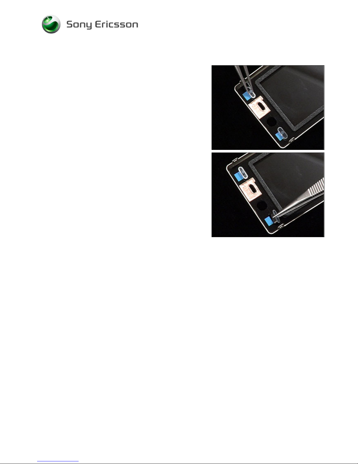
3.26 A/B Keys
REMOVAL
Follow the 2.1.1 – 2.1.4 Disassembly instructions!
Follow the 3.24 Removal instructions!
Use tweezers to remove the A/B keys.
INSTALLATION
Use tweezers to position the A/B keys.
Follow the 3.24 Installation instructions!
Follow the 4.1.7 – 4.1.10 Reassembly instructions!
Page 46
Working Instruction, Mechanical
3/000 21-1/FEA 209 544/134 E
Company Internal
© Sony Ericsson Mobile Communications AB
46(69)
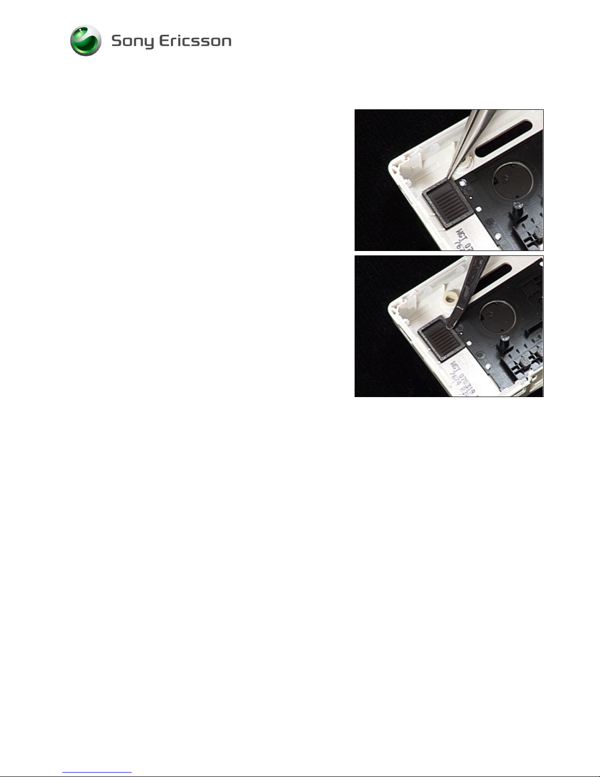
3.27 Loudspeaker Gasket
REMOVAL
Follow the 2.1.1 – 2.1.3 Disassembly instructions!
Use tweezers to remove the Loudspeaker gasket.
INSTALLATION
Use tweezers to position the Loudspeaker gasket.
Follow the 4.1.8 – 4.1.10 Reassembly instructions!
Page 47
Working Instruction, Mechanical
3/000 21-1/FEA 209 544/134 E
Company Internal
© Sony Ericsson Mobile Communications AB
47(69)
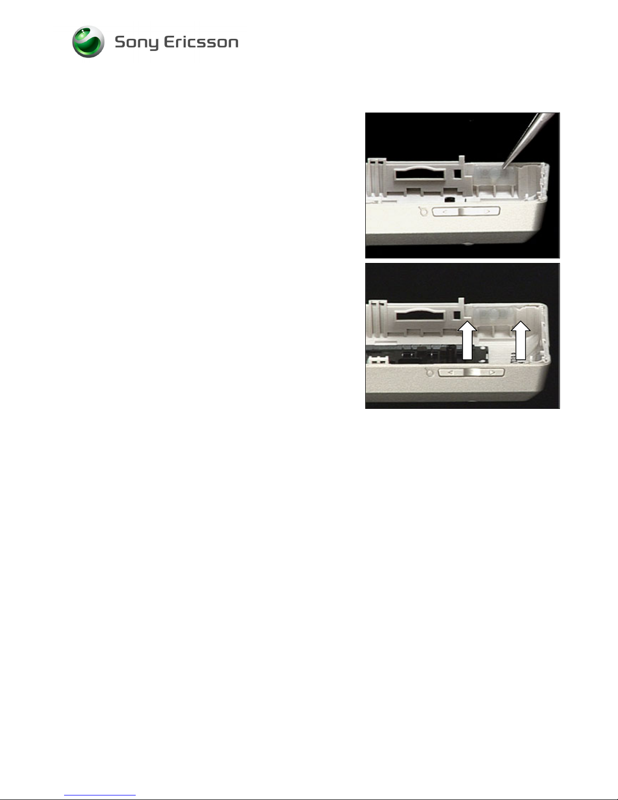
3.28 Music Player Key
REMOVAL
Follow the 2.1.1 – 2.1.3 Disassembly instructions!
Use tweezers to remove the Music play key.
INSTALLATION
Use tweezers to position the Music player key. Use the two
guiding.
Follow the 4.1.8 – 4.1.10 Reassembly instructions!
Page 48
Working Instruction, Mechanical
3/000 21-1/FEA 209 544/134 E
Company Internal
© Sony Ericsson Mobile Communications AB
48(69)
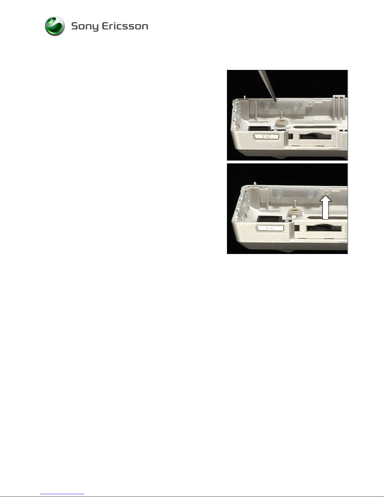
3.29 Volume Key
REMOVAL
Follow the 2.1.1 – 2.1.3 Disassembly instructions!
Use tweezers to remove the Volume key.
INSTALLATION
Use tweezers to position the Volume key. Use the guiding
pin.
Follow the 4.1.8 – 4.1.10 Reassembly instructions!
Page 49
Working Instruction, Mechanical
3/000 21-1/FEA 209 544/134 E
Company Internal
© Sony Ericsson Mobile Communications AB
49(69)
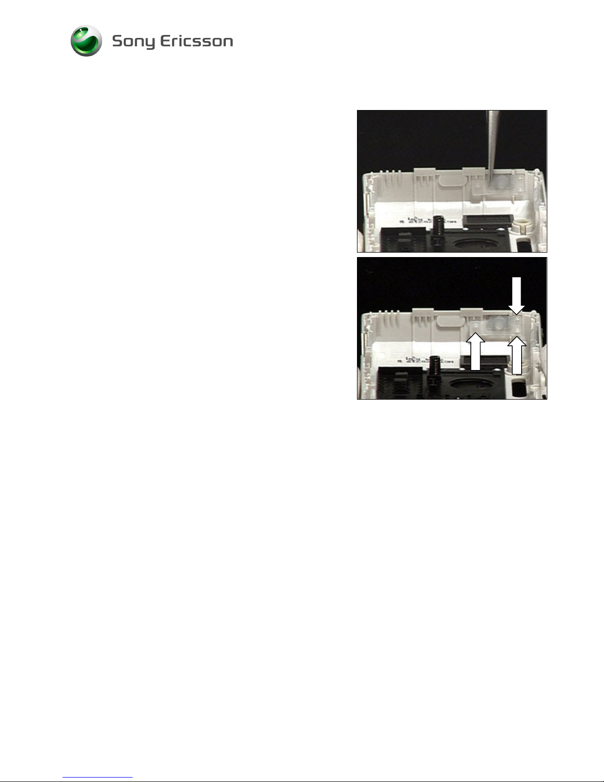
3.30 On/Off Key
REMOVAL
Follow the 2.1.1 – 2.1.3 Disassembly instructions!
Use tweezers to remove the On/Off key.
INSTALLATION
Use tweezers to position the On/Off key. Use the three
guiding pins.
Follow the 4.1.8 – 4.1.10 Reassembly instructions!
Page 50
Working Instruction, Mechanical
3/000 21-1/FEA 209 544/134 E
Company Internal
© Sony Ericsson Mobile Communications AB
50(69)
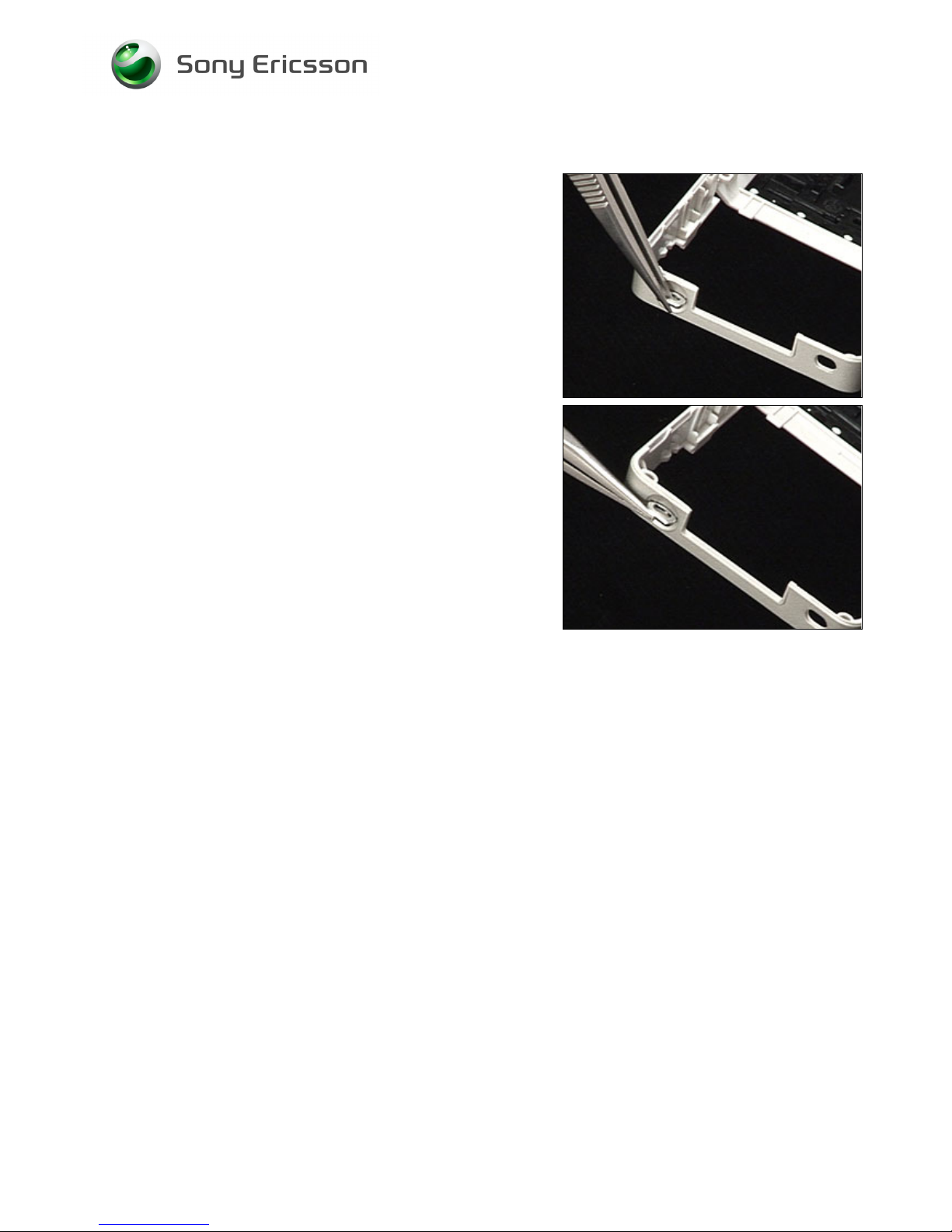
3.31 Handstrap Plate
REMOVAL
Follow the 2.1.1 – 2.1.3 Disassembly instructions!
Use tweezers to remove the Handstrap plate.
INSTALLATION
Use tweezers to position the Handstrap plate.
Follow the 4.1.8 – 4.1.10 Reassembly instructions!
Page 51
Working Instruction, Mechanical
3/000 21-1/FEA 209 544/134 E
Company Internal
© Sony Ericsson Mobile Communications AB
51(69)
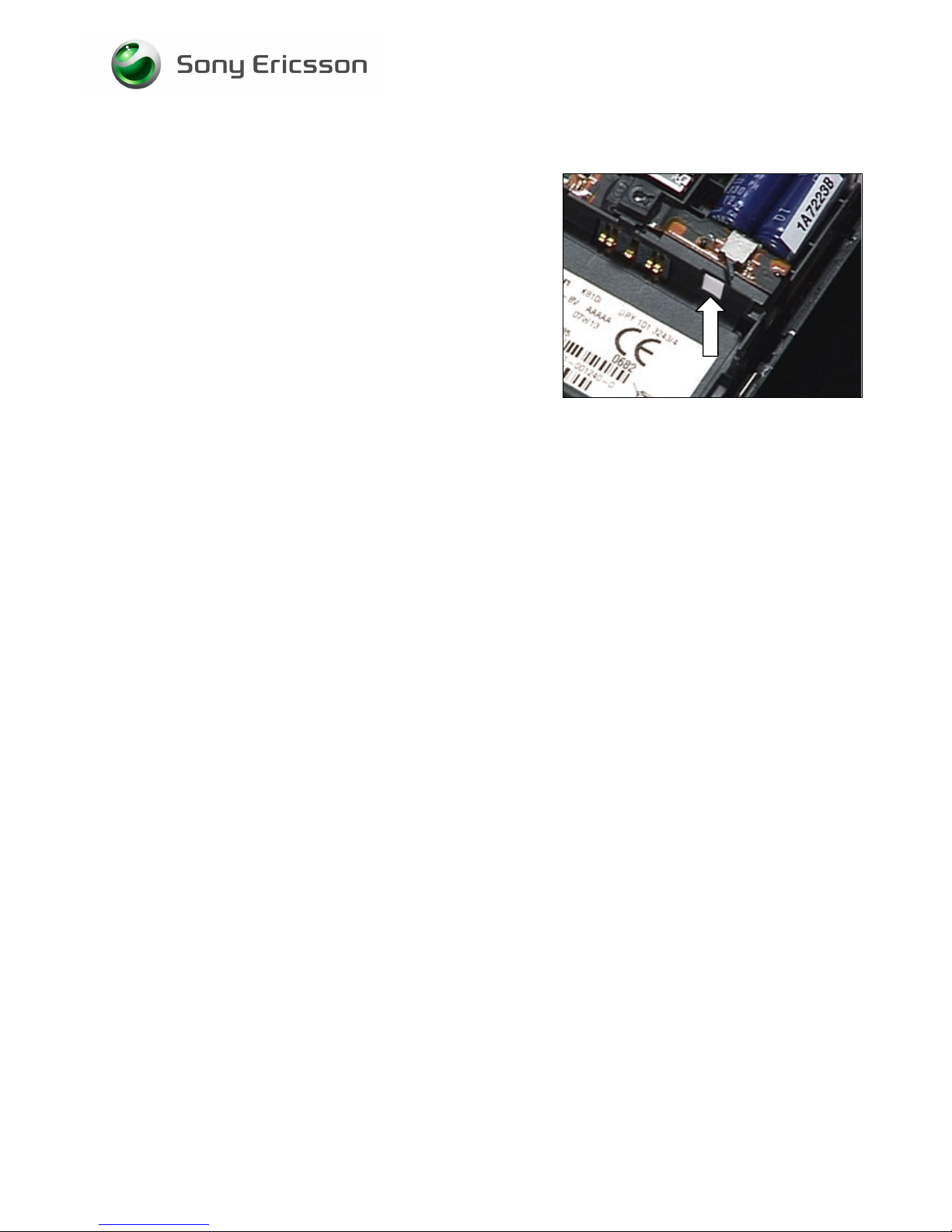
3.32 Liquid Indicator
INSPECTION
There is one Liquid Indicators located at the position of the
arrow
To get access to and to inspect the indicators:
Follow 2.1.1 – 2.1.3 Disassembly instructions!
REMOVAL
Remove the activated Liquid Intrusion Indicator with the
dentist hook and the tweezers.
INSTALLATION
Attach the new liquid intrusion indicator with the tweezers
and the dentist hook.
Follow the 4.1.8 – 4.1.10 Reassembly instructions!
Page 52
Working Instruction, Mechanical
3/000 21-1/FEA 209 544/134 E
Company Internal
© Sony Ericsson Mobile Communications AB
52(69)
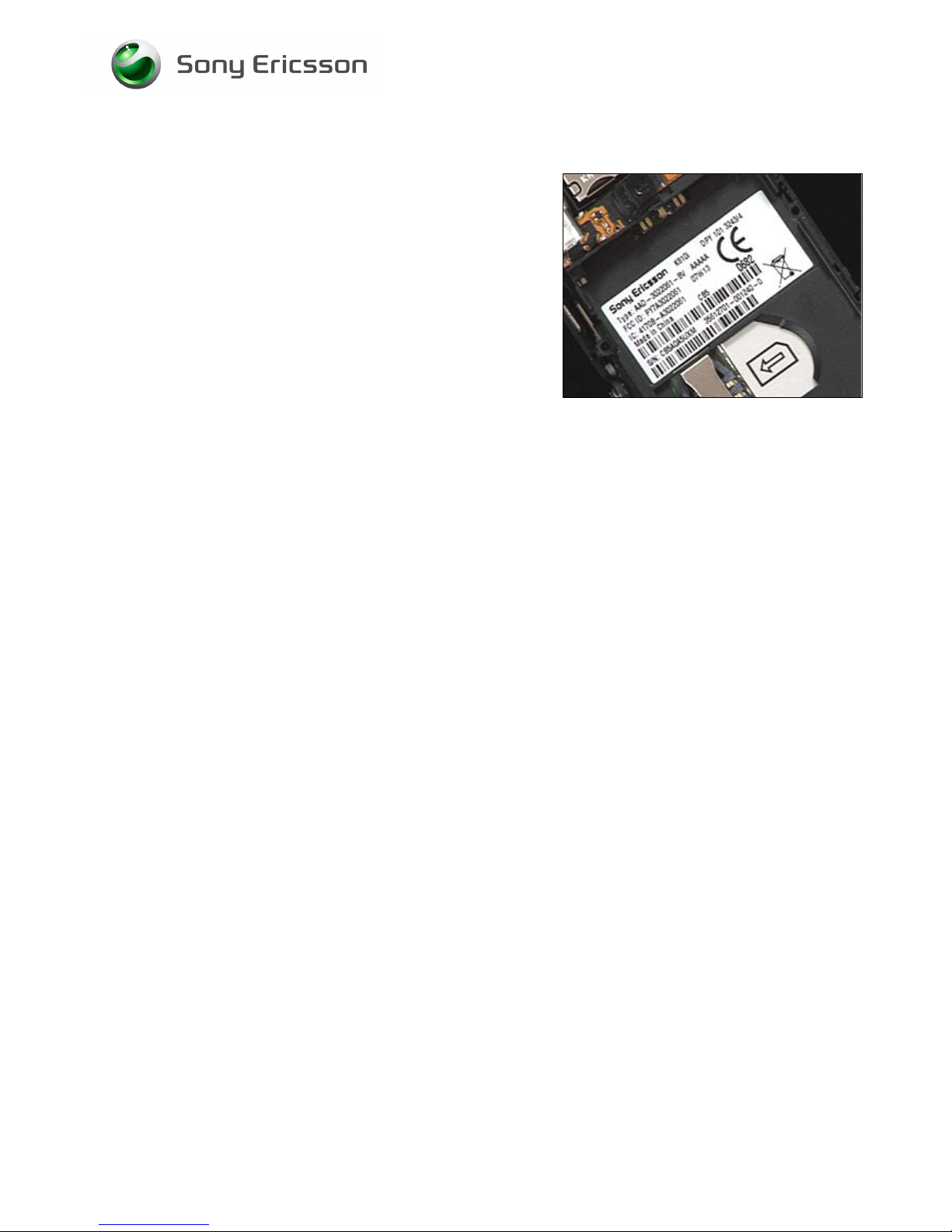
3.33 KRH Label
Follow the 2.1.1 – 2.1.3 Disassembly instructions!
• Read the old label and/or write the information into the
“Label make” program before removal
• Note the position of the label before removal
• Heat up the label by using hot air, if needed
• Carefully remove the label without causing scratches
• If there still are residues, clean the surface with isopropyl
alcohol
• Check that the proper label format is loaded in the Zebra
printer
• Write a new label by using the program “Label make”
and check that the printing is OK
• Take the new label and place it onto the frame as in the
adjacent picture
O
NE LABEL ONLY IS ALLOWED!
Follow the 4.1.8 – 4.1.10 Reassembly instructions!
Page 53
Working Instruction, Mechanical
3/000 21-1/FEA 209 544/134 E
Company Internal
© Sony Ericsson Mobile Communications AB
53(69)
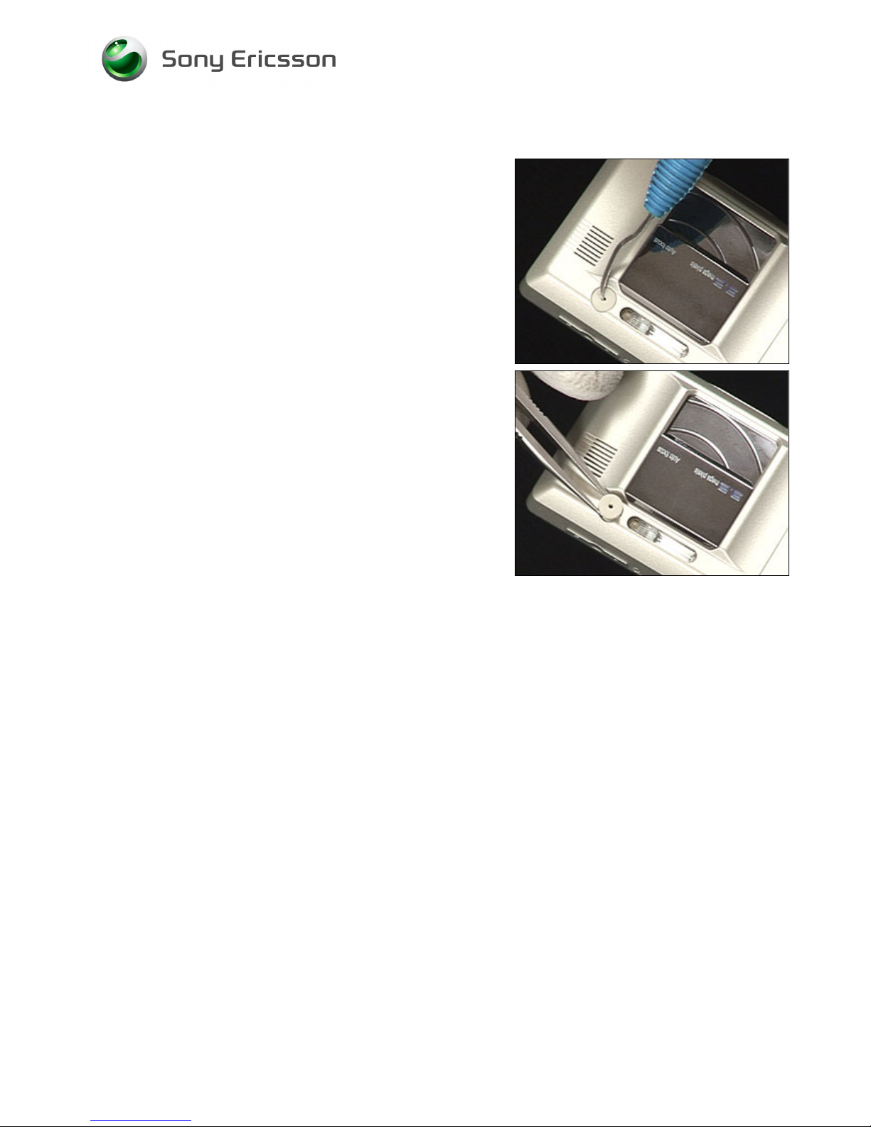
3.34 Plug (External Antenna)
REMOVAL
Use a dentist hook to remove the Plug (External antenna).
INSTALLATION
Use tweezers to position the Plug (External antenna).
Page 54
Working Instruction, Mechanical
3/000 21-1/FEA 209 544/134 E
Company Internal
© Sony Ericsson Mobile Communications AB
54(69)
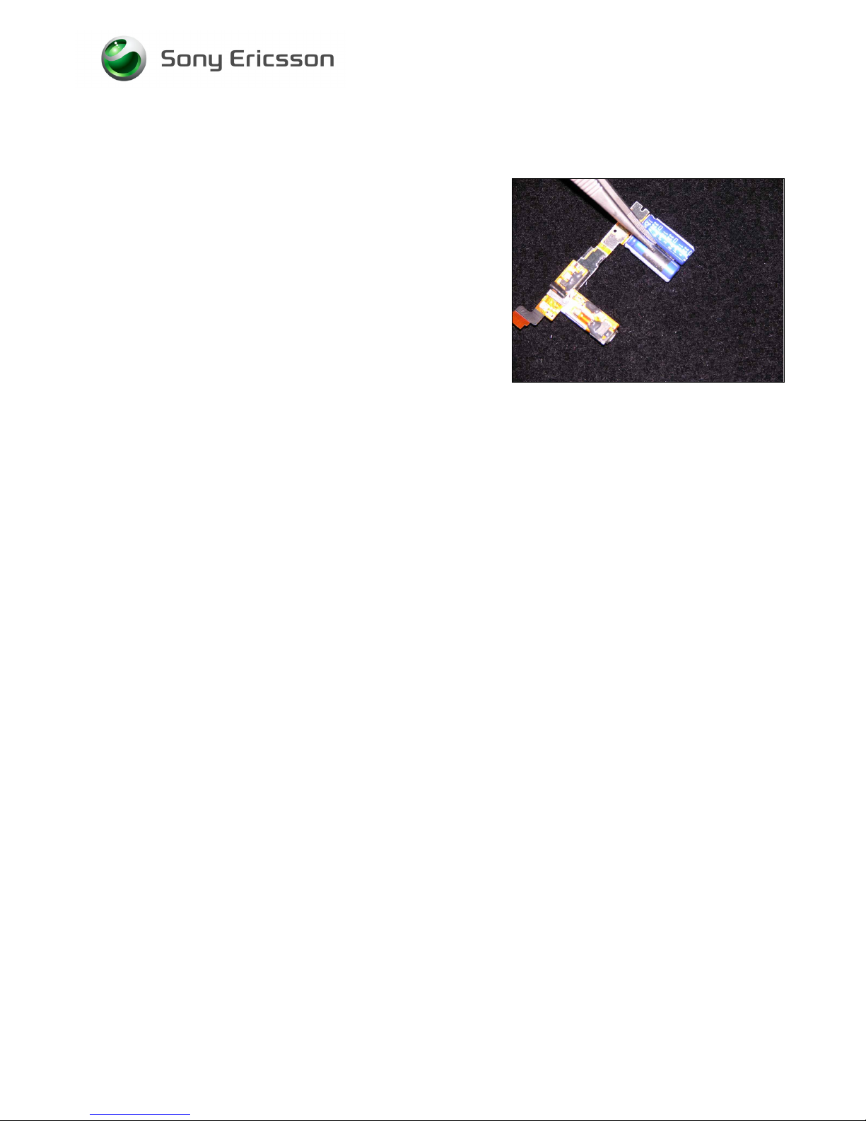
3.35 Tape (holder capacitor)
REMOVAL
Use a tweezers to remove the Tape (holder capacitor.
INSTALLATION
Use a tweezers to position the Tape (holder capacitor.
Page 55
Working Instruction, Mechanical
3/000 21-1/FEA 209 544/134 E
Company Internal
© Sony Ericsson Mobile Communications AB
55(69)
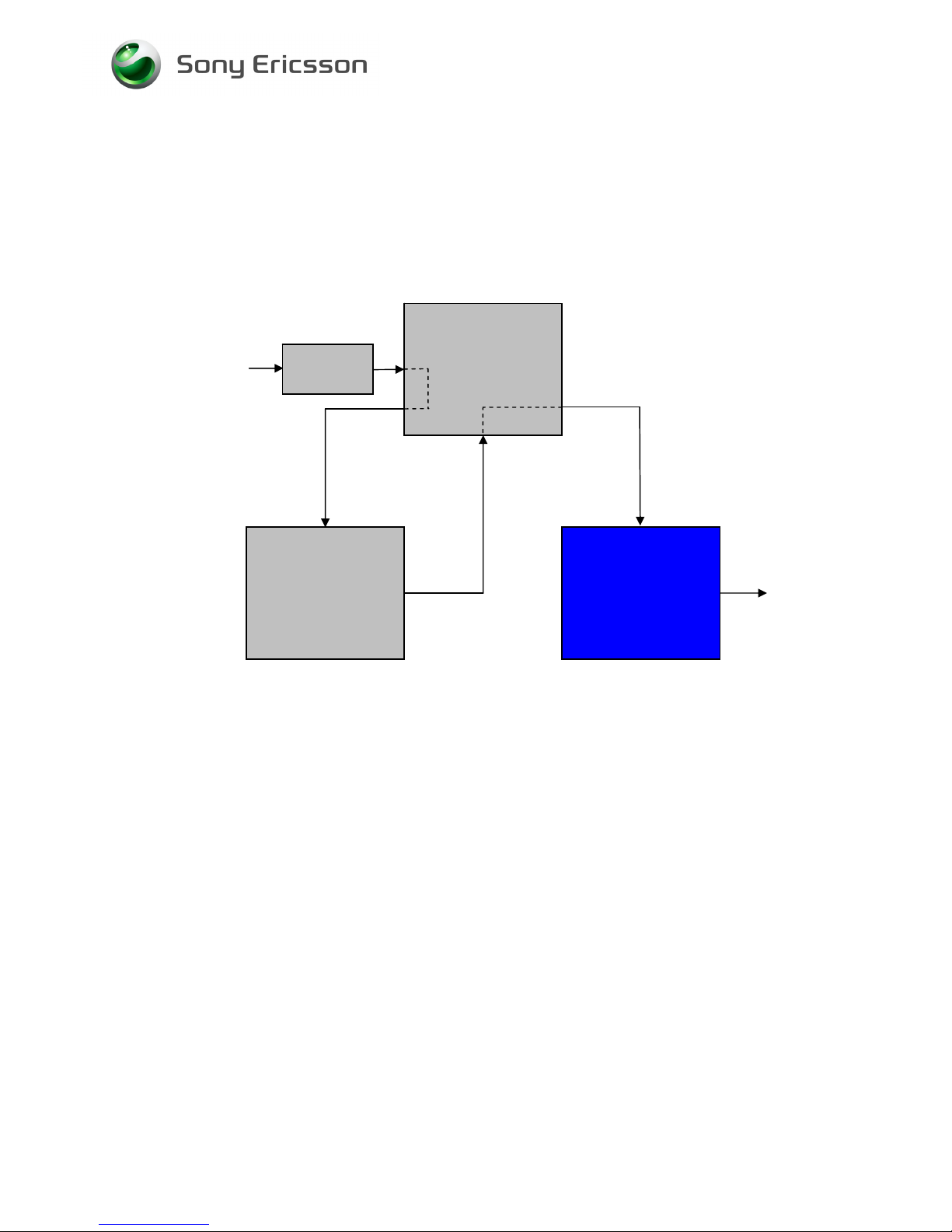
4 Reassembly
After replacing a part being listed in Replacements, the instruction of that section usually ends by
directing you to this Reassembly section with a specification of the instructions you have to carry out
in order to reassemble the phone.
Start
Done
REPLACEMENTS
DISASSEMBLY
REASSEMBLY
Contents
page
Page 56
Working Instruction, Mechanical
3/000 21-1/FEA 209 544/134 E
Company Internal
© Sony Ericsson Mobile Communications AB
56(69)
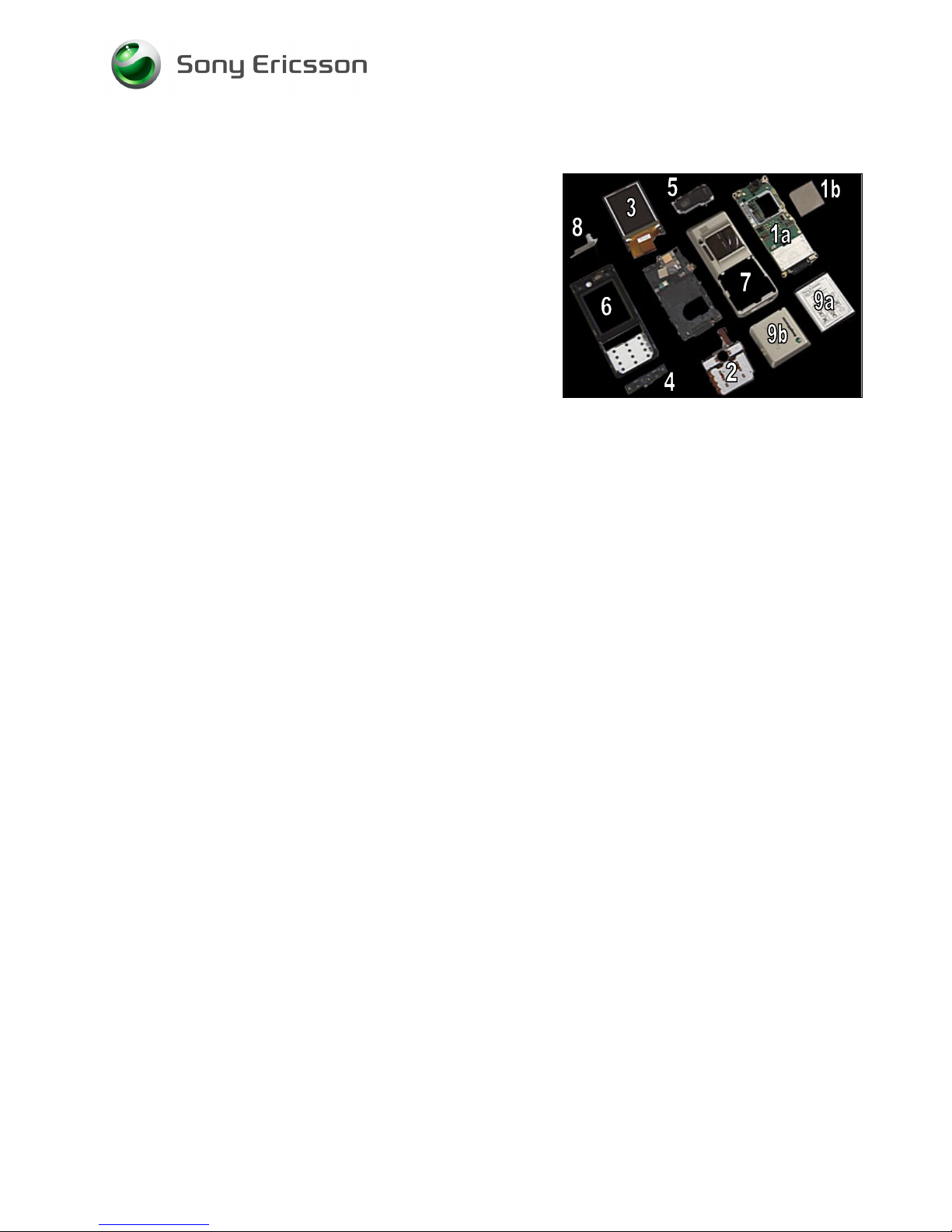
4.1 Overview
The reassembly is done in the following order:
1. PCB (a) & Shield Can Lid, Camera Assy (b)
2. Key Foil Complete
3. LCD
4. Function Keyboard Assy
5. Antenna/Speaker Box Assembly
6. Front
7. Antenna Cover Assembly
8. MS Cover
9. Batter
y (a)
& Battery Lid Assembly (b
)
Page 57
Working Instruction, Mechanical
3/000 21-1/FEA 209 544/134 E
Company Internal
© Sony Ericsson Mobile Communications AB
57(69)
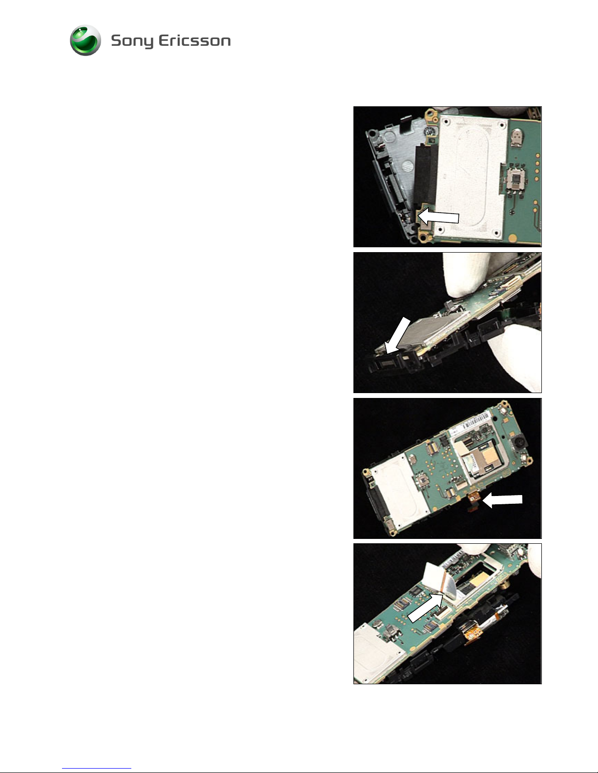
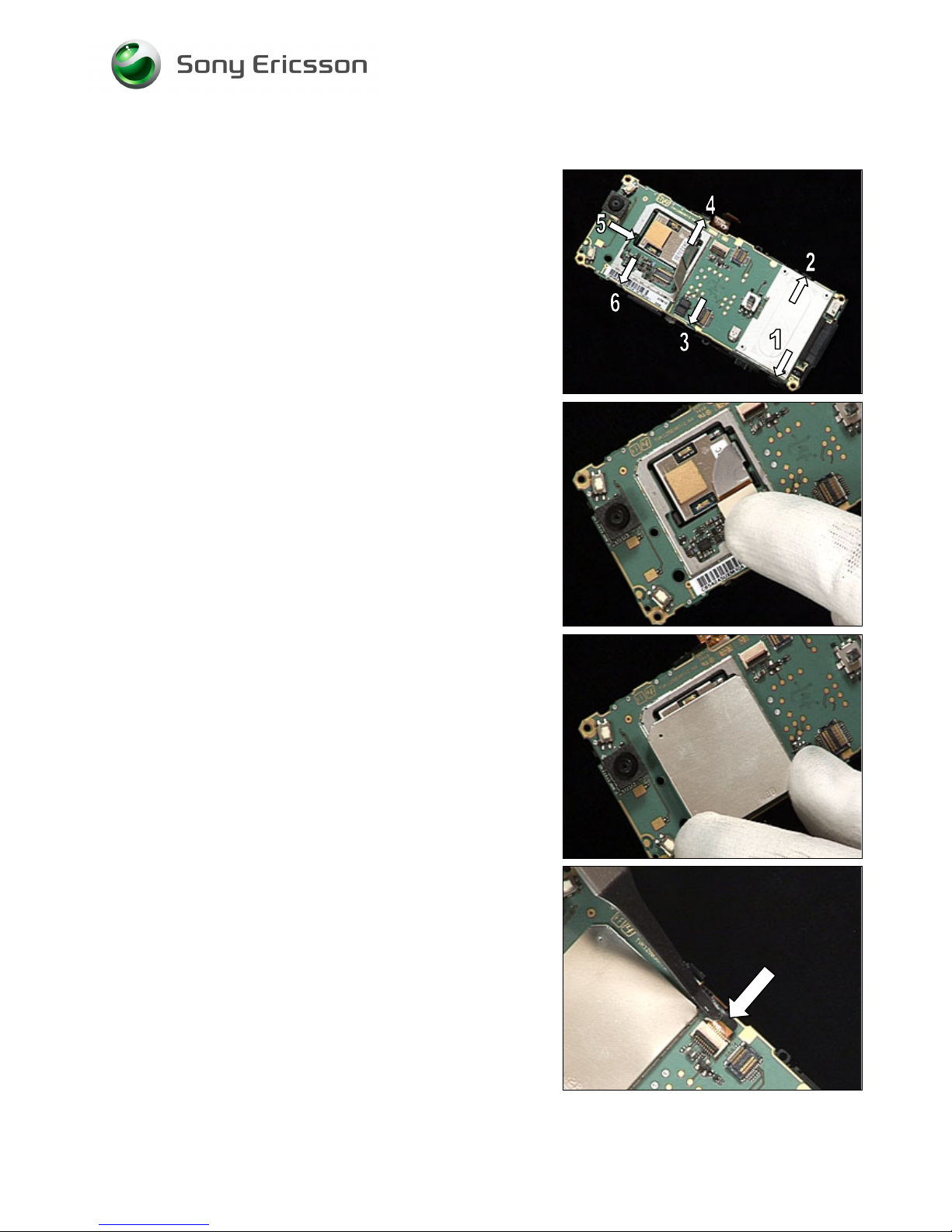
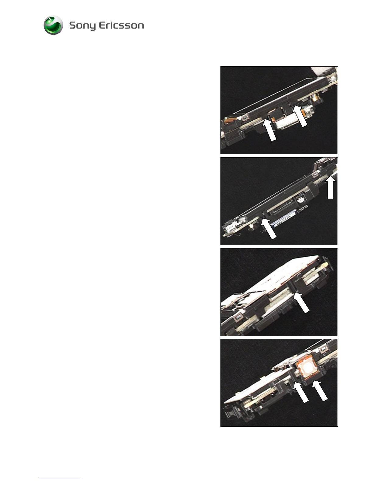
4.1.1 PCB & Shield Can Lid, Camera Assy
MAKE SURE THE BLUETOOTH ANTENNA´S CONTACT FINGERS
ARE UNDER THE PBA!
Place the indicated tab portion of the PBA into the slot on
the Frame assy.
Rotate the PBA so that the system connector is put into the
Frame assy.
SECURE ONCE AGAIN SO THAT THE BLUETOOTH ANTENNA´S
CONTACT FINGERS ARE UNDER THE PBA!
Make sure that the Xenon flash flex film is between the
Frame assy and the PBA.
Put out the Camera flex film through the large hole.
Page 58
Working Instruction, Mechanical
3/000 21-1/FEA 209 544/134 E
Company Internal
© Sony Ericsson Mobile Communications AB
58(69)
PCB & Shield Can Lid, Camera Assy continued
Snap the six latches in the order shown from the edge of
the PBA.
Plug the Camera connector to the connector on the PBA.
Use your fingers to install a new Shield can lid, camera
assy.
Use a flex film assembly tool and pull the flex film into the
connector.
Page 59
Working Instruction, Mechanical
3/000 21-1/FEA 209 544/134 E
Company Internal
© Sony Ericsson Mobile Communications AB
59(69)
PCB & Shield Can Lid, Camera Assy continued
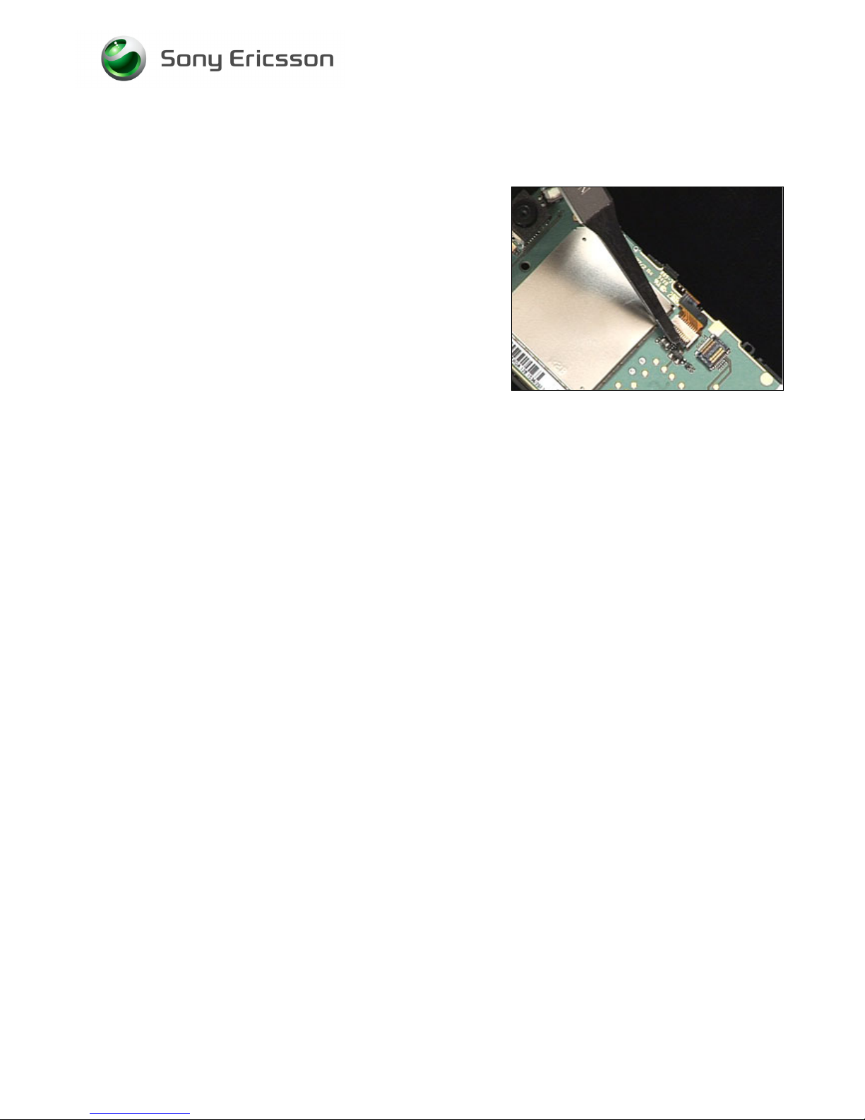
Rotate the black retaining bar of the connector away from
the flex film.
Page 60
Working Instruction, Mechanical
3/000 21-1/FEA 209 544/134 E
Company Internal
© Sony Ericsson Mobile Communications AB
60(69)
4.1.2 Key Foil Complete
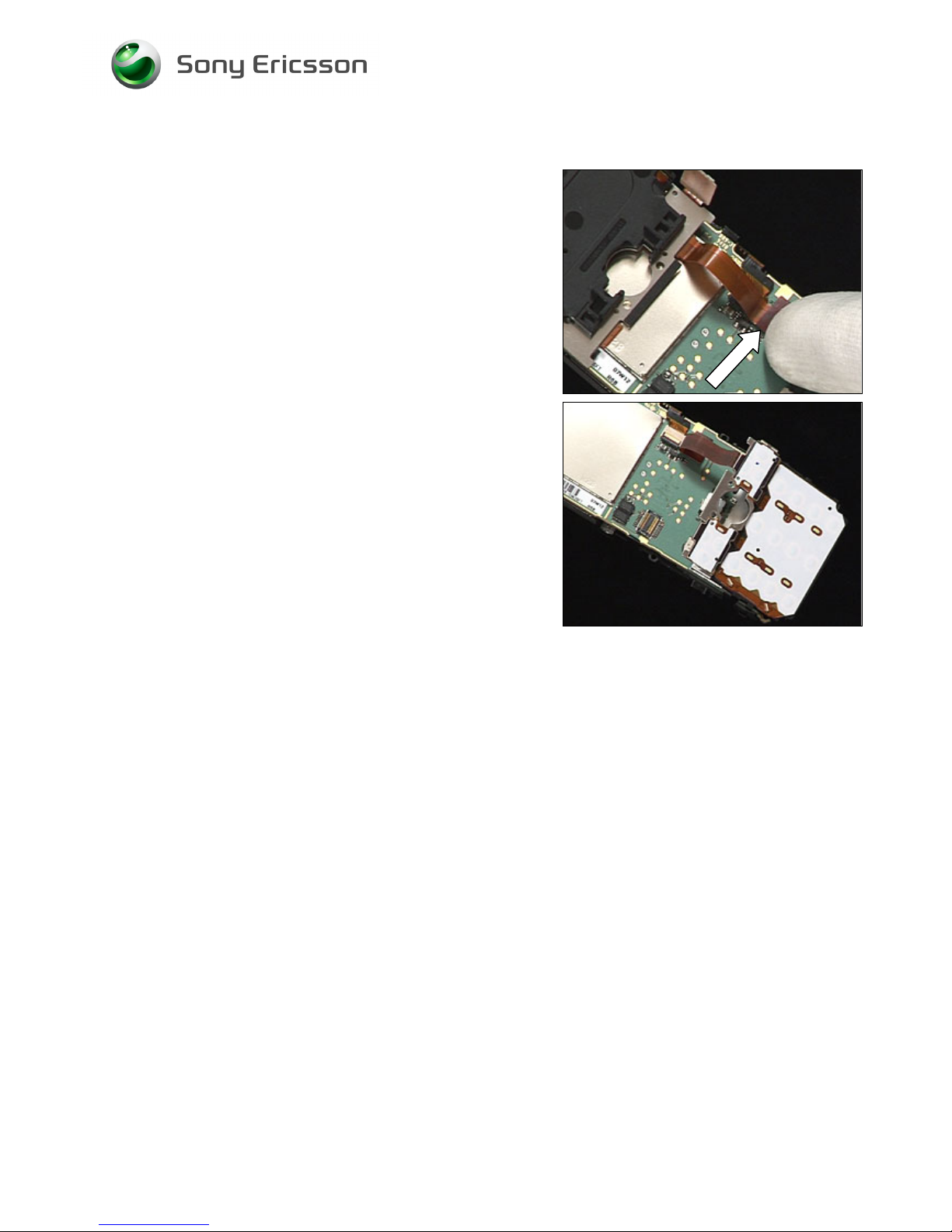
Lay the Key foil complete upside down over the Shield can
lid, camera assy. Plug the Key foil complete flex film to the
BtB connector on the PBA with your fingers.
Rotate the Key foil complete and position it over the system
connector.
Page 61
Working Instruction, Mechanical
3/000 21-1/FEA 209 544/134 E
Company Internal
© Sony Ericsson Mobile Communications AB
61(69)
4.1.3 LCD
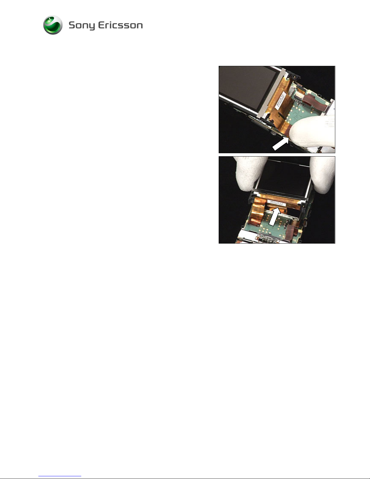
Plug the LCD flex film into the BtB connector on the PBA
with your fingers.
Rotate the LCD down onto the PBA so that the LCD flex
film folds underneath the LCD.
Page 62
Working Instruction, Mechanical
3/000 21-1/FEA 209 544/134 E
Company Internal
© Sony Ericsson Mobile Communications AB
62(69)
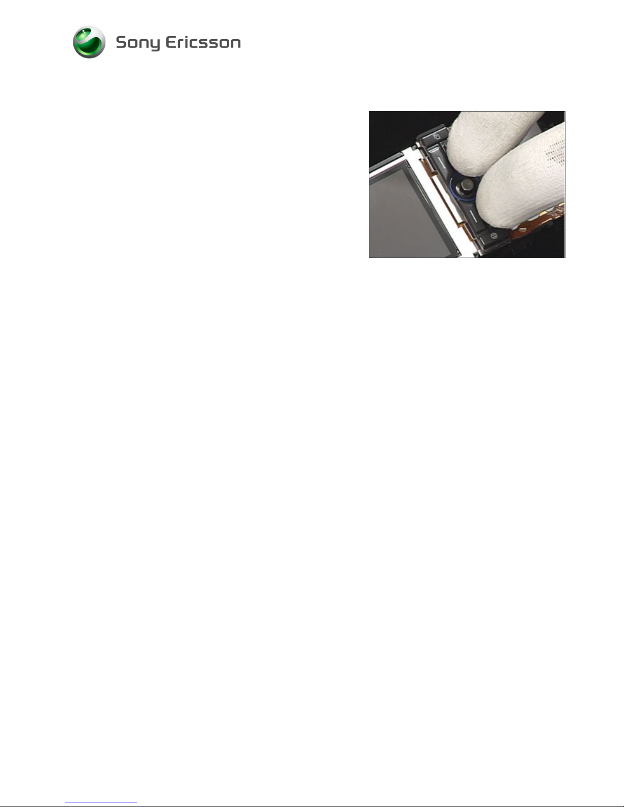
4.1.4 LCD/Key Foil Complete attachment
Snap the two latches of the LCD holder.
Do the same thing on the opposite side.
Snap the latch of the Key foil complete.
Do the same thing on the other side and slide the camera
switch into its slot in the Frame assy.
Page 63
Working Instruction, Mechanical
3/000 21-1/FEA 209 544/134 E
Company Internal
© Sony Ericsson Mobile Communications AB
63(69)
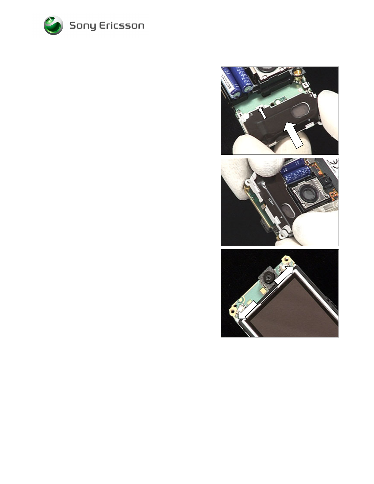
4.1.5 Function Keyboard Assy
Use your fingers to position the Function keyboard assy.
Page 64
Working Instruction, Mechanical
3/000 21-1/FEA 209 544/134 E
Company Internal
© Sony Ericsson Mobile Communications AB
64(69)
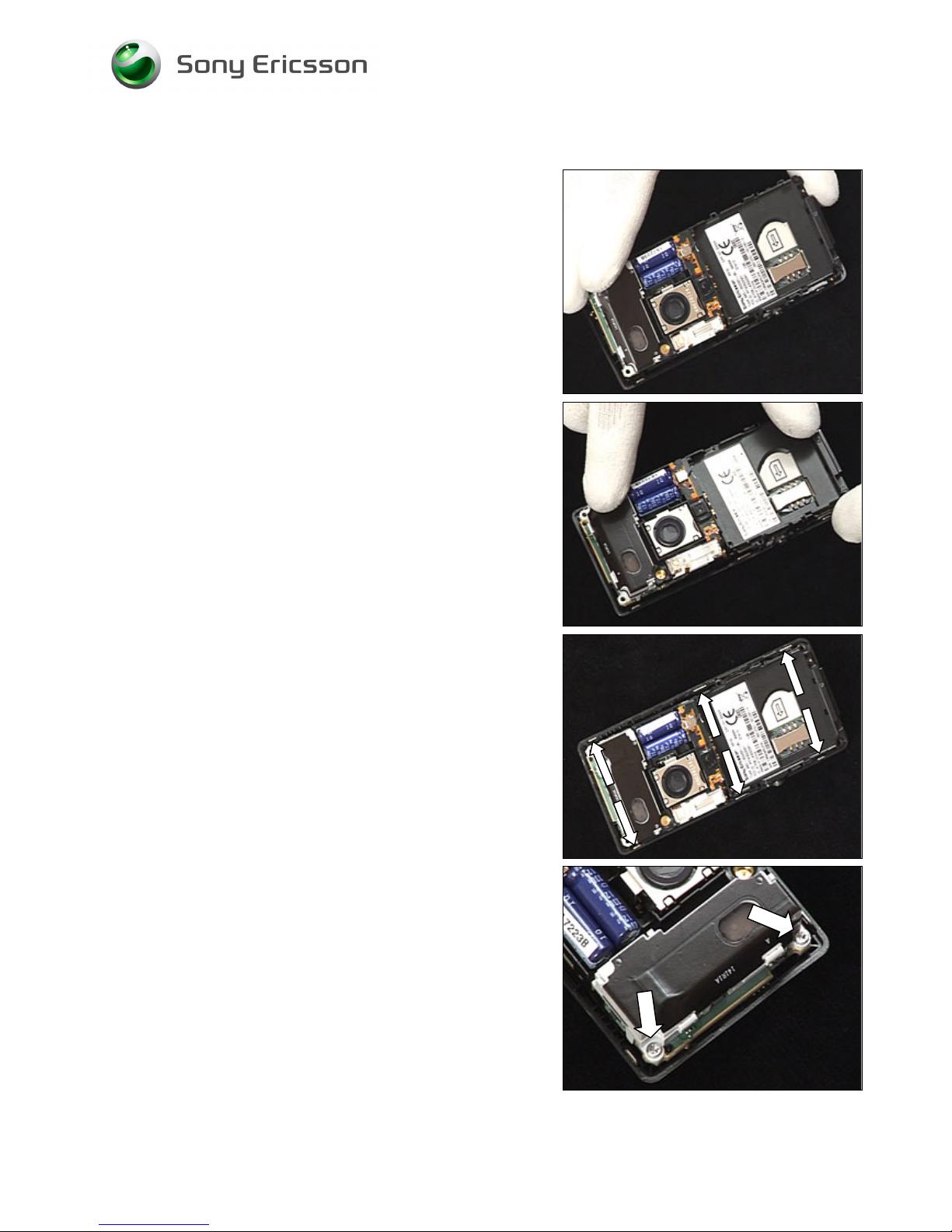
4.1.6 Antenna/Speaker Box Assembly
Insert the tab portion of the Antenna/Speaker box assembly
in the slot under the capacitors.
Use your fingers to position the Antenna/Speaker box
assembly and snap it on the PBA.
Visually inspect so that the hooks has snapped!
Page 65
Working Instruction, Mechanical
3/000 21-1/FEA 209 544/134 E
Company Internal
© Sony Ericsson Mobile Communications AB
65(69)
4.1.7 Front Unit
Insert the camera key side of the Core unit in the Front
complete.
Rotate opposite side of the Core unit into the Front
complete.
Snap the Core unit and the Front complete together with
your fingers.
Install the two silver screws using torque screwdriver at 22
Ncm with a T6 bit.
Page 66
Working Instruction, Mechanical
3/000 21-1/FEA 209 544/134 E
Company Internal
© Sony Ericsson Mobile Communications AB
66(69)
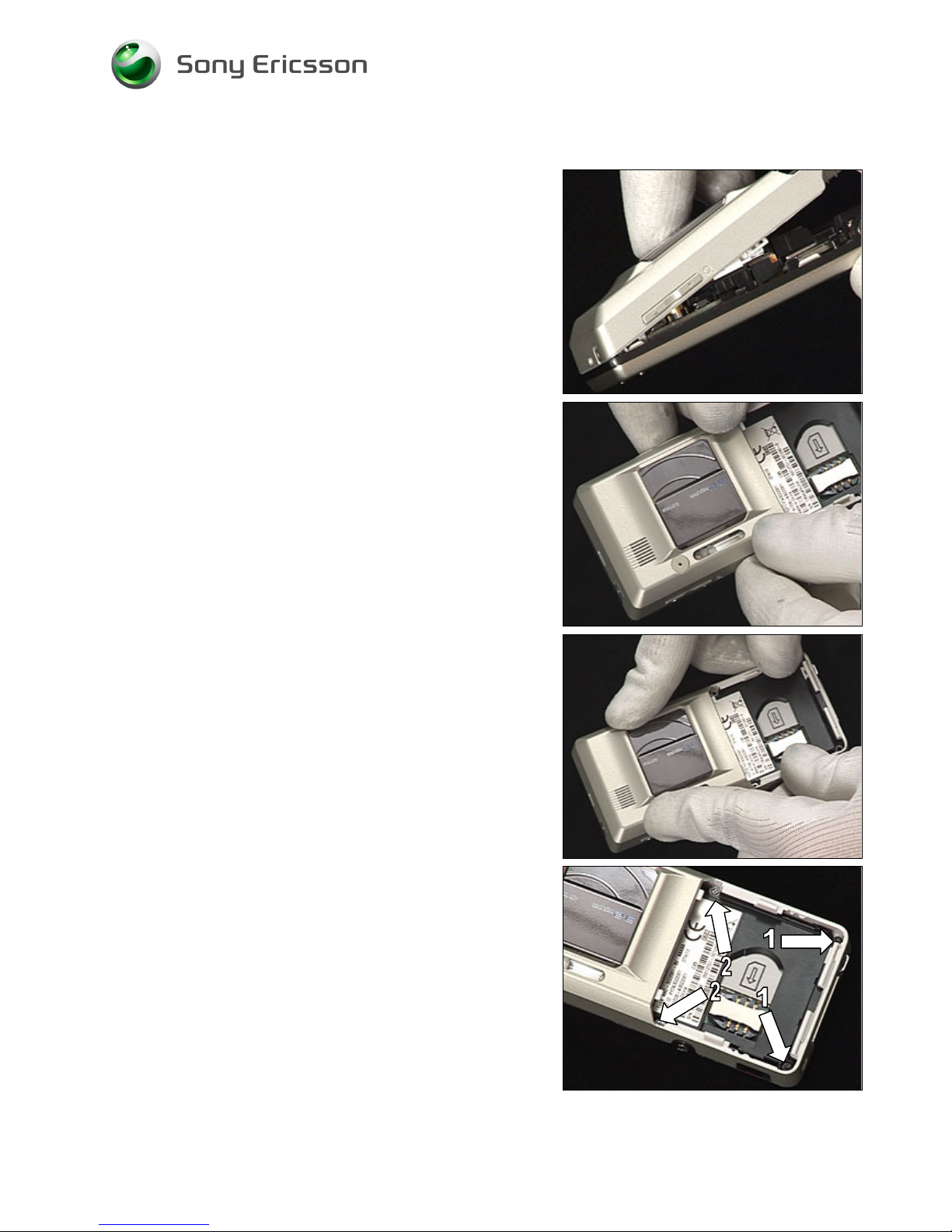
4.1.8 Antenna Cover Assembly
Use your fingers to position the top of the Antenna cover
assembly on the Front unit.
Rotate the Antenna cover assembly down onto the phone.
Use your fingers to snap the phone together.
Install the two black screws (numbered 1) with torque
screwdriver at 22 Ncm with a T6 bit.
Install two screws (numbered 2) with torque screwdriver at
10 Ncm with a JCIS.
Page 67
Working Instruction, Mechanical
3/000 21-1/FEA 209 544/134 E
Company Internal
© Sony Ericsson Mobile Communications AB
67(69)
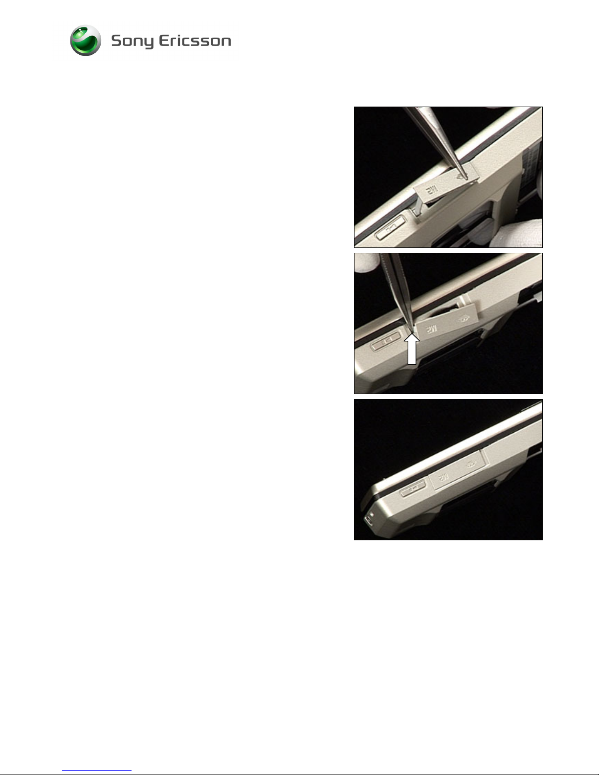
4.1.9 MS Cover
Use tweezers to position the MS cover.
Use tweezers to press the tab portion of the MS cover into
the small hole in the memory stick cavity.
Use your fingers to snap the MS cover into the memory
stick cavity.
Page 68
Working Instruction, Mechanical
3/000 21-1/FEA 209 544/134 E
Company Internal
© Sony Ericsson Mobile Communications AB
68(69)
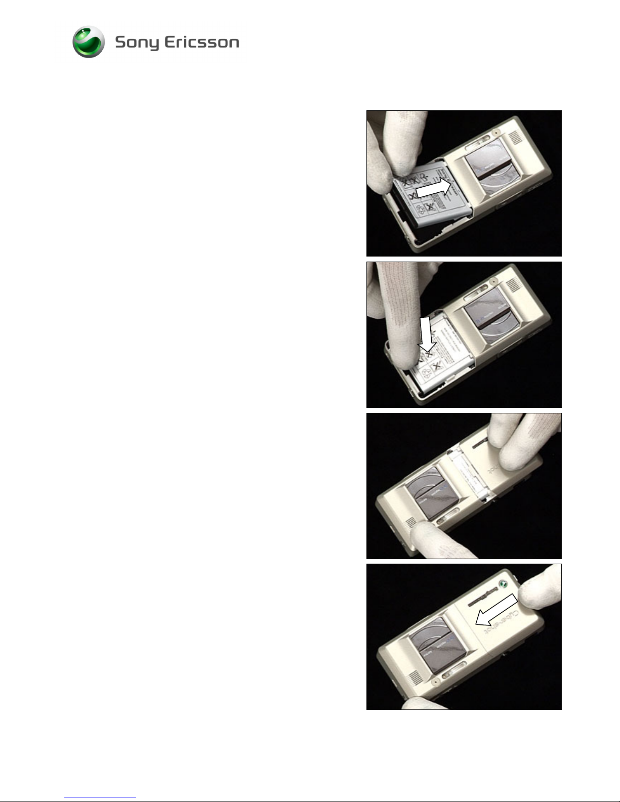
4.1.10 Battery & Battery Lid Assembly
Insert the contact end of the battery into the cavity.
Press the battery down in the cavity.
Position the battery cover as shown.
Slide the battery cover into place. Make sure it snaps into
place.
Page 69

Working Instruction, Mechanical
3/000 21-1/FEA 209 544/134 E
Company Internal
© Sony Ericsson Mobile Communications AB
69(69)
5 Revision history
Rev. Date Changes / Comments
A 2007-04-20 Initial release
B 2007-05-10 Added some information in Chapter 2.1.7
C 2007-05-15 Due to system problem. No changes made on content
D 2007-05-21 Added Tape (holder capacitor)
E 2007-06-19 Added support for K818
 Loading...