

Page 1

Working Instruction, Mechanical
Working Instruction, Mechanical
Applicable for K610i, K610m, and V630i
CONTENTS
1 Introduction ..............................................................................3
1.1 Equipment.................................................................................4
1.2 General cautions......................................................................5
2 Disassembly.............................................................................6
2.1 Overview ...................................................................................6
2.1.1 Sub Assembly Lid (Battery) & Battery...................................7
2.1.2 Cover (Rear) .........................................................................8
2.1.3 Sub Assembly Case (Front)..................................................9
2.1.4 Key (Main)...........................................................................11
2.1.5 Sub Assembly Case (Rear).................................................12
3 Replacements.........................................................................13
3.1 Sub Assembly Lid (Battery) ..................................................14
3.2 Cover (Rear)............................................................................14
3.3 Sub Assembly Case (Front) ..................................................14
3.4 Key (Main) ...............................................................................14
3.5 Cap (RF) ..................................................................................15
3.6 Co-Branding Label.................................................................16
3.7 M2 Cover (MS) ........................................................................17
3.8 Plate (LCD)..............................................................................18
3.9 TFT LCD Module 176 x 220....................................................20
3.10 Key Flex Module.....................................................................22
3.11 Frame (PWB)...........................................................................25
3.12 Receiver ..................................................................................27
3.13 Cushion (Frame).....................................................................28
3.14 Water Indicator.......................................................................29
3.15 Key (Power).............................................................................30
3.16 Key (Volume) ..........................................................................31
3.17 Key (Music).............................................................................32
3.18 Key (Cam)................................................................................33
3.19 Vibrator....................................................................................34
3.20 Loudspeaker...........................................................................35
3.21 Cushion (Speaker)..................................................................36
3.22 Sub Assembly Case (Rear)....................................................37
3.23 System Connector..................................................................38
3.24 Main Antenna..........................................................................39
3.25 Camera Shield ........................................................................41
3.26 Camera, 2M Pixel....................................................................43
3.27 Label........................................................................................45
3/000 21-1/FEA 209 544/109 B
©
Sony Ericsson Mobile Communications AB
Approved according to 1/109 41-FCP 119 00
06
Page 2

Working Instruction, Mechanical
4 Reassembly............................................................................46
4.1 Overview .................................................................................46
4.1.1 Sub Assembly Case (Rear).................................................47
4.1.2 Key (Main)...........................................................................48
4.1.3 Sub Assembly Case (Front)................................................49
4.1.4 Cover (Rear) .......................................................................50
4.1.5 Battery & Sub Assembly Lid (Battery).................................52
5 Revision history.....................................................................53
3/000 21-1/FEA 209 544/109 B
©
Sony Ericsson Mobile Communications AB
2(53)
Page 3
Working Instruction, Mechanical
1 Introduction
K610
V630i
3/000 21-1/FEA 209 544/109 B
©
Sony Ericsson Mobile Communications AB
3(53)
Page 4

Working Instruction, Mechanical
1.1 Equipment
SPECIAL TOOLS
• NTZ 112 459 Torque screwdriver (or equivalent)
• NTZ 112 288 Torx bit no. 6
• NTZ 112 1052 JCIS bit
• NTZ 112 1067 Mega camera removal tool
• NTZ 112 521 Flex film assembly tool
• NTZ 112 302/2 Front opening tool
STANDARD TOOLS
• Dentist hook
• Blunt pair of tweezers
• Guitar pick
ESD EQUIPMENT
Protect the phone from ESD damages whenever it has
been opened by using:
• ESD-wristband
• ESD-gloves
LABEL EQUIPMENT
The following special equipment is required when replacing
or installing a new label:
• Hot air flow solder station
• Zebra printer connected to computer
3/000 21-1/FEA 209 544/109 B
©
Sony Ericsson Mobile Communications AB
4(53)
Page 5
Working Instruction, Mechanical
1.2 General cautions
The following cautions are considered to be generic for all phone models and will not be repeated in
the Disassembly, Replacements and Reassembly sections:
•
KEEP ALL CONTACT SURFACES CLEAN
•
BE CAREFUL WHEN USING TOOLS LIKE THE DENTIST HOOK, TWEEZERS, OPENING TOOLS, GUITAR PICK
ETC. TO AVOID SCRATCHES OR DAMAGES TO THE EXTERIOR AND INTERIOR PARTS OF THE PHONE
BE CAREFUL NOT TO DAMAGE ANY CONTACT SPRINGS
•
•
NEVER TOUCH THE DISPLAY GLASS
•
USE AIR BLOW EQUIPMENT TO KEEP THE DISPLAY MODULE DUST FREE
!
!
!
!
!
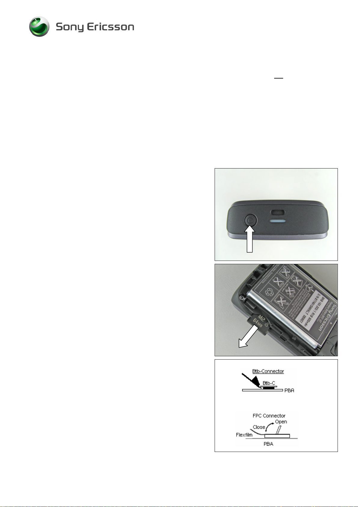
Press the On/Off button to turn off the phone.
Check that the memory stick has been removed.
How to open a board-to-board connector with the front
opening tool.
How to open and close a FPC connector (often done with a
dentist hook).
3/000 21-1/FEA 209 544/109 B
©
Sony Ericsson Mobile Communications AB
5(53)
Page 6

Working Instruction, Mechanical
2 Disassembly
When you are going to replace a part being listed in Replacements, the instruction of that section
usually begins by directing you to this Disassembly section with a specification of the instructions you
have to carry out in order to disassemble the phone as far as needed before returning to
Replacements for the actual replacement.
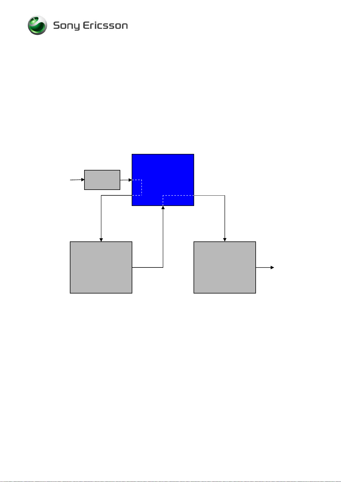
REPLACEMENTS
Start
Contents
page
DISASSEMBLY
2.1 Overview
REASSEMBLY
Done
The disassembly is done in the following sequence:
1. Sub Assembly Lid (Battery) (a) & Battery (b)
2. Cover (Rear)
3. Sub Assembly Case (Front)
4. Key (Main)
5. Sub Assembly Case (Rear)
3/000 21-1/FEA 209 544/109 B
©
Sony Ericsson Mobile Communications AB
6(53)
Page 7
Working Instruction, Mechanical
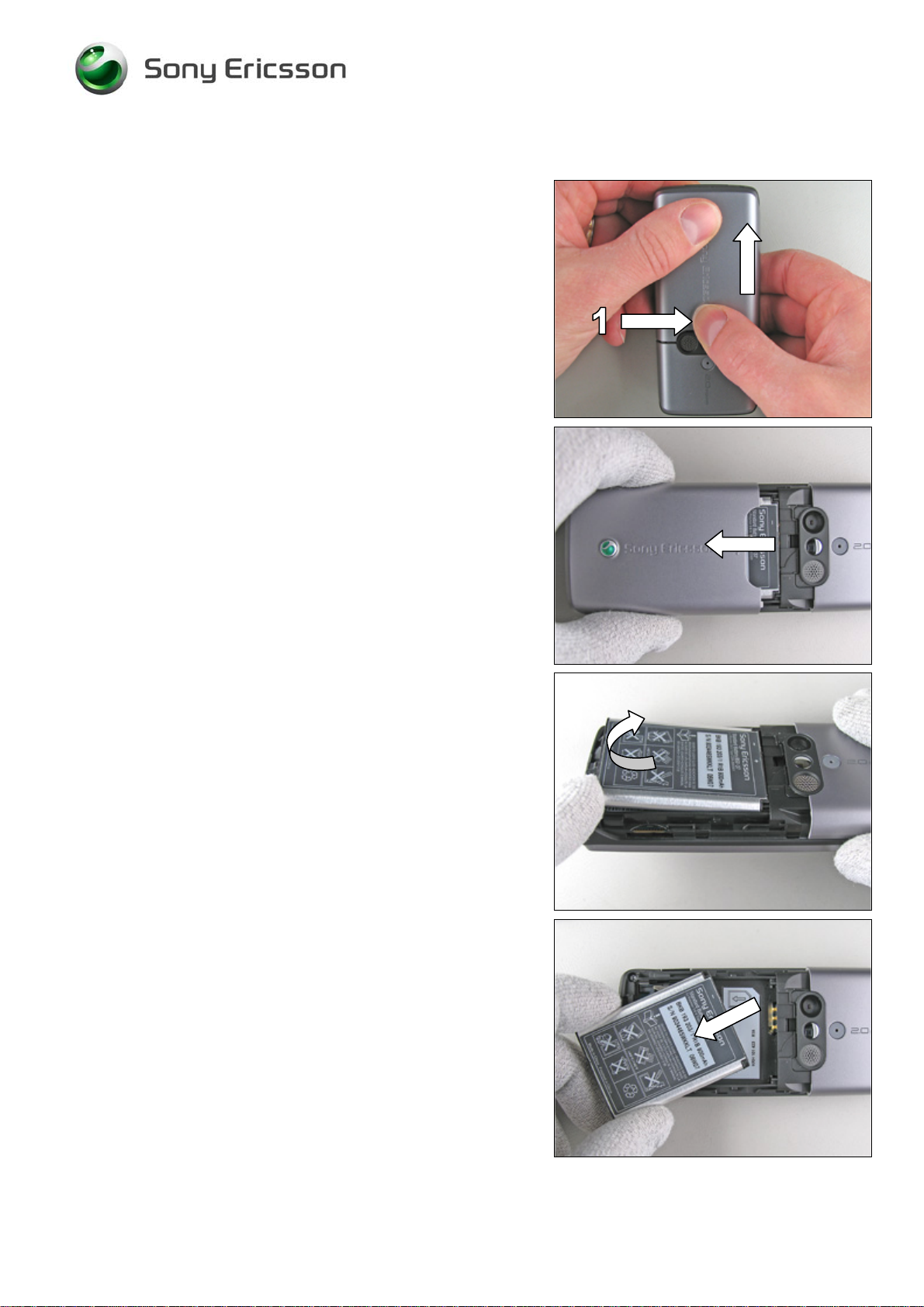
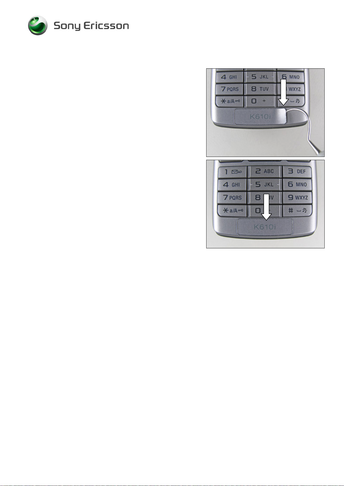
2.1.1 Sub Assembly Lid (Battery) & Battery
Press (quite hard) on the battery lid until you get a gap –
use your thumb at the arrow (1).
Slide down the lid from its mounted position towards the
bottom of the phone and remove it.
Lift the battery straight up at the bottom to release it.
If not released, turning the phone around at the same time
will make it become released.
Remove the battery from the phone.
3/000 21-1/FEA 209 544/109 B
©
Sony Ericsson Mobile Communications AB
7(53)
Page 8
Working Instruction, Mechanical
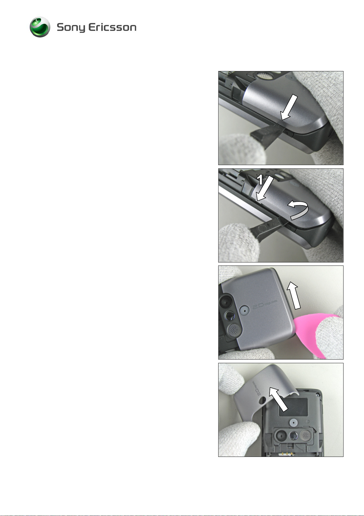
2.1.2 Cover (Rear)
Carefully insert the front opening tool where the music key
is located.
B
E VERY CAREFUL WITH THE SMALL PLASTIC LOCKS INSIDE
(1) –
THE COVER
THEY MIGHT EASILY BREAK
!
Gently bend with the front opening tool until the rear cover
starts to become loose from the rear case.
S
OMETIMES THE REAR COVER “POPS” AWAY FROM THE
PHONE WHEN DISASSEMBLED
!
Move the guitar pick along the gap (start at the corner) until
the rear cover is loose.
Remove the rear cover.
3/000 21-1/FEA 209 544/109 B
©
Sony Ericsson Mobile Communications AB
8(53)
Page 9
Working Instruction, Mechanical
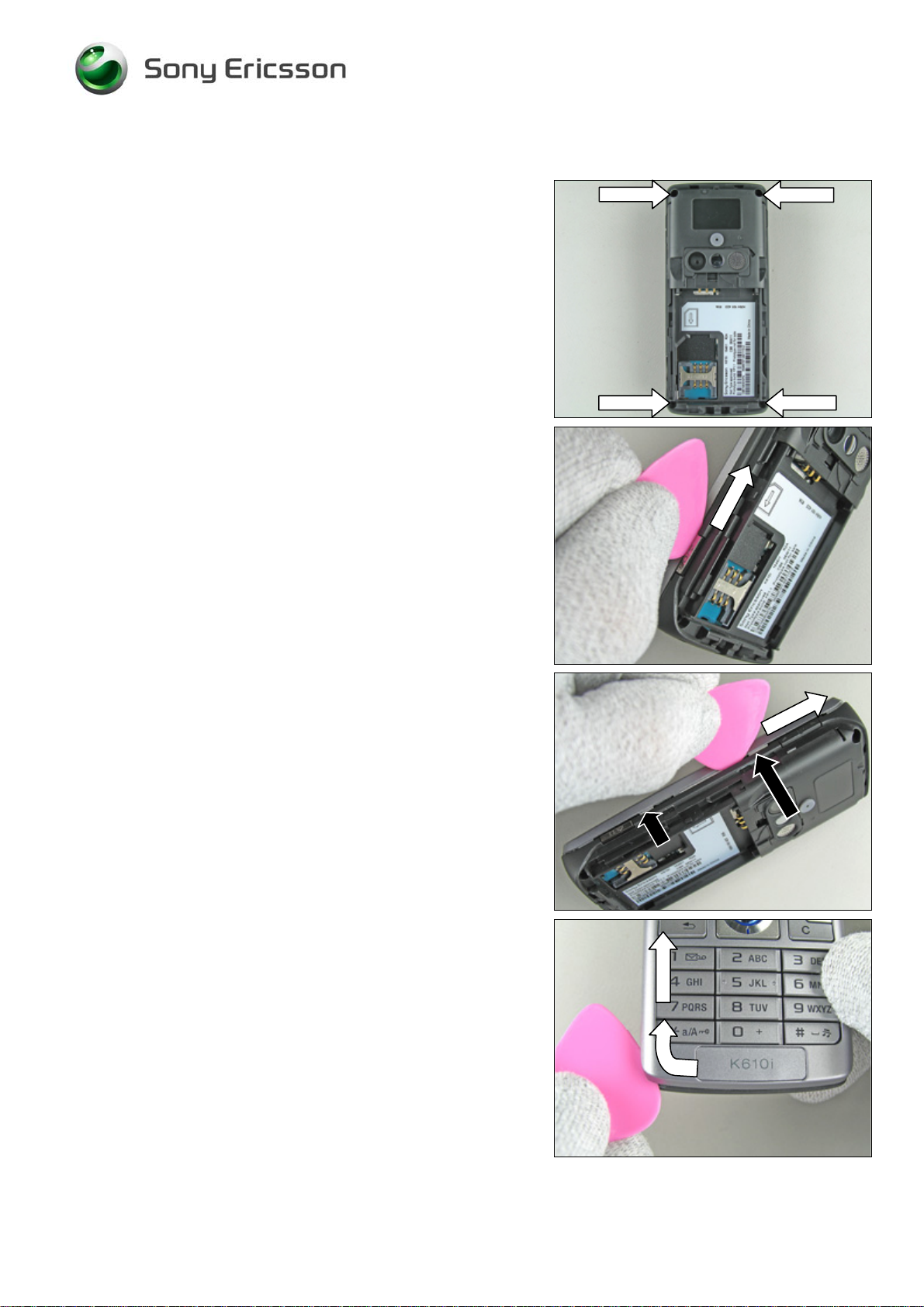
2.1.3 Sub Assembly Case (Front)
Remove the four inside screws from the rear case by using
torx bit no. 6.
R
EPLACE THE SCREWS IF THEY ARE DAMAGED, OTHERWISE
THEY CAN BE REUSED
!
Gently but firmly move the guitar pick along the gap,
starting at the camera key.
Continue forward with the guitar pick until the front case is
loose on this side.
The snap hooks to be released are located as indicated by
the black arrows.
Continue up and around the corner and forward on to the
opposite side, starting at the system connector, and repeat
the two steps above.
3/000 21-1/FEA 209 544/109 B
©
Sony Ericsson Mobile Communications AB
9(53)
Page 10

Working Instruction, Mechanical
Sub Assembly Case (Front) continued
DON’
T BEND THE FRONT CASE TOO MUCH SINCE IT CAN CAUSE
SERIOUS DAMAGE TO THE FRONT
Gently wiggle the front case slightly side to side to make the
entire front become loose.
!
Gently lift up the front case and remove it.
Front case removed.
3/000 21-1/FEA 209 544/109 B
©
Sony Ericsson Mobile Communications AB
10(53)
Page 11
Working Instruction, Mechanical
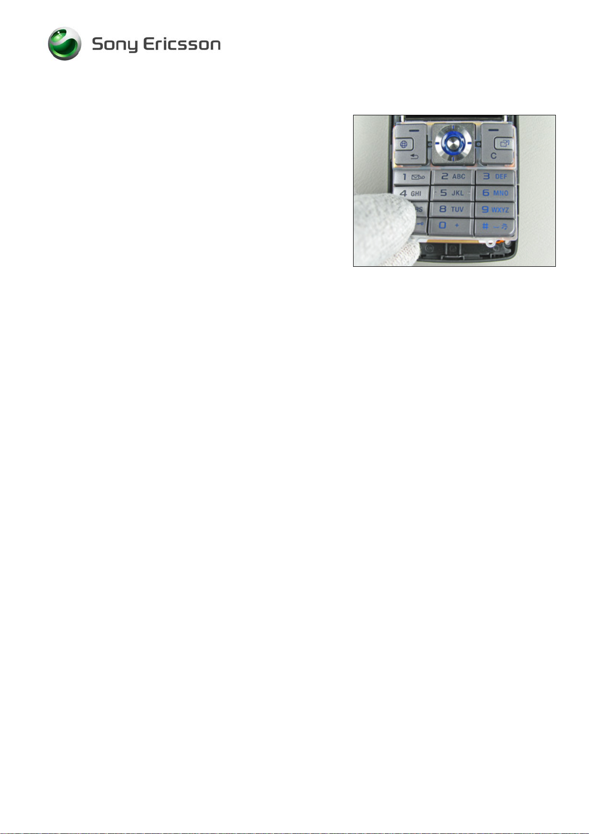
2.1.4 Key (Main)
Remove the main key by hand.
Sometimes the main key stays in the front, sometimes it
falls out.
3/000 21-1/FEA 209 544/109 B
©
Sony Ericsson Mobile Communications AB
11(53)
Page 12
Working Instruction, Mechanical
2.1.5 Sub Assembly Case (Rear)
Gently bend with the front opening tool at the centre of the
top under the frame/PBA unit until it is released from the
rear case.
Remove the frame/PBA unit completely from the rear case.
Rear case removed.
3/000 21-1/FEA 209 544/109 B
©
Sony Ericsson Mobile Communications AB
12(53)
Page 13
Working Instruction, Mechanical
3 Replacements
Search for the part to be replaced on the Contents page and go to that instruction to be found in this
Replacements section.
The instruction usually begins by directing you to the Disassembly section with a specification of the
instructions you have to carry out in order to disassemble the phone as far as needed before the
actual replacement.
Go back to this Replacements section and carry out the instruction.
The instruction usually ends by directing you to the Reassembly section with a specification of the
instructions you have to carry out in order to reassemble the phone.
REPLACEMENTS
Start
Contents
page
DISASSEMBLY REASSEMBLY
Done
3/000 21-1/FEA 209 544/109 B
©
Sony Ericsson Mobile Communications AB
13(53)
Page 14

Working Instruction, Mechanical
3.1 Sub Assembly Lid (Battery)
Follow the 2.1.1 Disassembly instructions!
Prepare the new battery lid.
Follow the 4.1.5 Reassembly instructions!
3.2 Cover (Rear)
Follow the 2.1.1 - 2.1.2 Disassembly instructions!
Prepare the new rear cover.
Follow the 4.1.4 - 4.1.5 Reassembly instructions!
3.3 Sub Assembly Case (Front)
Follow the 2.1.1 - 2.1.3 Disassembly instructions!
Prepare the new front case.
Follow the 4.1.3 - 4.1.5 Reassembly instructions!
3.4 Key (Main)
Follow the 2.1.1 - 2.1.4 Disassembly instructions!
Prepare the new main key.
Follow the 4.1.2 – 4.1.5 Reassembly instructions!
3/000 21-1/FEA 209 544/109 B
©
Sony Ericsson Mobile Communications AB
14(53)
Page 15
Working Instruction, Mechanical
3.5 Cap (RF)
REMOVAL
Remove the RF cap with a dentist hook.
INSTALLATION
Insert a new RF cap with your fingers.
3/000 21-1/FEA 209 544/109 B
©
Sony Ericsson Mobile Communications AB
15(53)
Page 16
Working Instruction, Mechanical
3.6 Co-Branding Label
REMOVAL
Gently remove the co-branding label with a dentist hook.
INSTALLATION
Attach a new co-branding label with the tweezers or by
hand.
Keep the pressure on for a few seconds to secure a good
attachment.
3/000 21-1/FEA 209 544/109 B
©
Sony Ericsson Mobile Communications AB
16(53)
Page 17

Working Instruction, Mechanical
3.7 M2 Cover (MS)
T
HIS INSTRUCTION IS VALID FOR
REMOVAL
Remove the M2 cover with your fingers.
K618
ONLY
!
INSTALLATION
Mount a new M2 cover with your fingers.
Correctly mounted M2 cover.
3/000 21-1/FEA 209 544/109 B
©
Sony Ericsson Mobile Communications AB
17(53)
Page 18

Working Instruction, Mechanical
3.8 Plate (LCD)
REMOVAL
Follow the 2.1.1 – 2.1.4 Disassembly instructions!
Gently turn back the upper part of the key flex module by
using your fingers or the front opening tool.
B
E CAREFUL WITH THE DENTIST HOOK
!
Start to remove the LCD plate with a dentist hook.
Remove the LCD plate from the phone.
INSTALLATION
Put the LCD plate in its proper position.
3/000 21-1/FEA 209 544/109 B
©
Sony Ericsson Mobile Communications AB
18(53)
Page 19

Working Instruction, Mechanical
Plate (LCD) continued
Press on the plate with your fingers to secure it to the
phone.
Start by pushing the key flex module under the two hooks
(by the arrows), and then press it down against the LCD
plate.
Properly mounted LCD plate and key flex module.
Follow the 4.1.2 – 4.1.5 Reassembly instructions!
3/000 21-1/FEA 209 544/109 B
©
Sony Ericsson Mobile Communications AB
19(53)
Page 20

Working Instruction, Mechanical
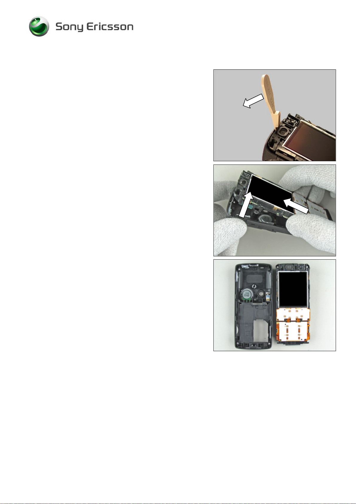
3.9 TFT LCD Module 176 x 220
REMOVAL
Follow the 2.1.1 – 2.1.4 Disassembly instructions!
Follow the 3.8 Removal instructions!
Put the front opening tool into the cavity on the right hand
side of the TFT LCD module and gently bend until it starts
to become loose.
Turn the TFT LCD module upwards.
B
E CAREFUL WITH THE LCD FLEX FILM!
Gently bend with the front opening tool under the TFT LCD
module’s board-to-board connector like the picture shows
until the connector becomes loose from the main PBA.
TFT LCD module 176 x 220 removed.
3/000 21-1/FEA 209 544/109 B
©
Sony Ericsson Mobile Communications AB
20(53)
Page 21

Working Instruction, Mechanical
TFT LCD Module 176 x 220 continued
INSTALLATION
Start like this before installing the new TFT LCD module.
Connect the TFT LCD module’s board-to-board connector
to the main PBA by using your fingers (1).
Then move the LCD into position on the frame (2).
Gently turn the TFT LCD module against the frame until it is
in the correct position.
TFT LCD module correctly mounted into the phone.
D
O NOT TOUCH THE LCD GLASS SURFACE
B
LOW AWAY DUST WITH AN IONIZED AIR GUN OR BLOWER
.
Follow the 3.8 Installation instructions!
Follow the 4.1.2 – 4.1.5 Reassembly instructions!
3/000 21-1/FEA 209 544/109 B
©
Sony Ericsson Mobile Communications AB
.
21(53)
Page 22

Working Instruction, Mechanical
3.10 Key Flex Module
REMOVAL
Follow the 2.1.1 – 2.1.5 Disassembly instructions!
This is the key flex module.
Release the camera buttons flex film with a dentist hook.
Gently bend with the front opening tool under the key flex
module’s board-to-board connector like the picture shows
until the connector become loose from the main PBA.
Use the front opening tool to bend under the key flex
module until it becomes loose.
3/000 21-1/FEA 209 544/109 B
©
Sony Ericsson Mobile Communications AB
22(53)
Page 23

Working Instruction, Mechanical
Key Flex Module continued
Remove the key flex module with your fingers.
INSTALLATION
Place the new key flex module by hand.
Connect the key flex module’s board-to-board connector to
the main PBA by using your fingers.
Fold down the camera flex over the two guide pins on the
frame.
3/000 21-1/FEA 209 544/109 B
©
Sony Ericsson Mobile Communications AB
23(53)
Page 24

Working Instruction, Mechanical
Key Flex Module continued
Gently push the key flex module’s upper half under the two
hooks on the frame.
Follow the 4.1.1 – 4.1.5 Reassembly instructions!
3/000 21-1/FEA 209 544/109 B
©
Sony Ericsson Mobile Communications AB
24(53)
Page 25

Working Instruction, Mechanical
3.11 Frame (PWB)
REMOVAL
Follow the 2.1.1 – 2.1.5 Disassembly instructions!
BE VERY CAREFUL WITH THE MAIN PBA
Use the front opening tool to bend under the main PBA until
it becomes loose.
!
Continue to work your way around the main PBA...
…with the front opening tool.
Remove the main PBA by hand.
3/000 21-1/FEA 209 544/109 B
©
Sony Ericsson Mobile Communications AB
25(53)
Page 26

Working Instruction, Mechanical
Frame (PWB) continued
INSTALLATION
Start like this!
Place the main PBA over the frame.
Snap the main PBA in place onto the frame.
Make sure that the main PBA is properly mounted onto the
frame.
Follow the 4.1.1 – 4.1.5 Reassembly instructions!
3/000 21-1/FEA 209 544/109 B
©
Sony Ericsson Mobile Communications AB
26(53)
Page 27

Working Instruction, Mechanical
3.12 Receiver
REMOVAL
Follow the 2.1.1 – 2.1.5 Disassembly instructions!
Follow the 3.11 Removal instructions!
Raise the receiver out of its cavity with a dentist hook …
… and remove it with the tweezers.
INSTALLATION
D
O NOT TOUCH OR BEND THE CONTACT SPRINGS
Position the receiver and press gently on each side with the
tweezers.
Check that the contact springs are in good condition and
that they are not deformed.
Follow the 3.11 Installation instructions!
Follow the 4.1.1 – 4.1.5 Reassembly instructions!
!
3/000 21-1/FEA 209 544/109 B
©
Sony Ericsson Mobile Communications AB
27(53)
Page 28

Working Instruction, Mechanical
3.13 Cushion (Frame)
REMOVAL
Follow the 2.1.1 – 2.1.5 Disassembly instructions!
Follow the 3.11 Removal instructions!
This picture just points out the position of the cushion on the
frame (under the key flex module).
Remove the cushion with a dentist hook.
INSTALLATION
Attach a new cushion with the tweezers.
Follow the 3.11 Installation instructions!
Follow the 4.1.1 – 4.1.5 Reassembly instructions!
3/000 21-1/FEA 209 544/109 B
©
Sony Ericsson Mobile Communications AB
28(53)
Page 29

Working Instruction, Mechanical
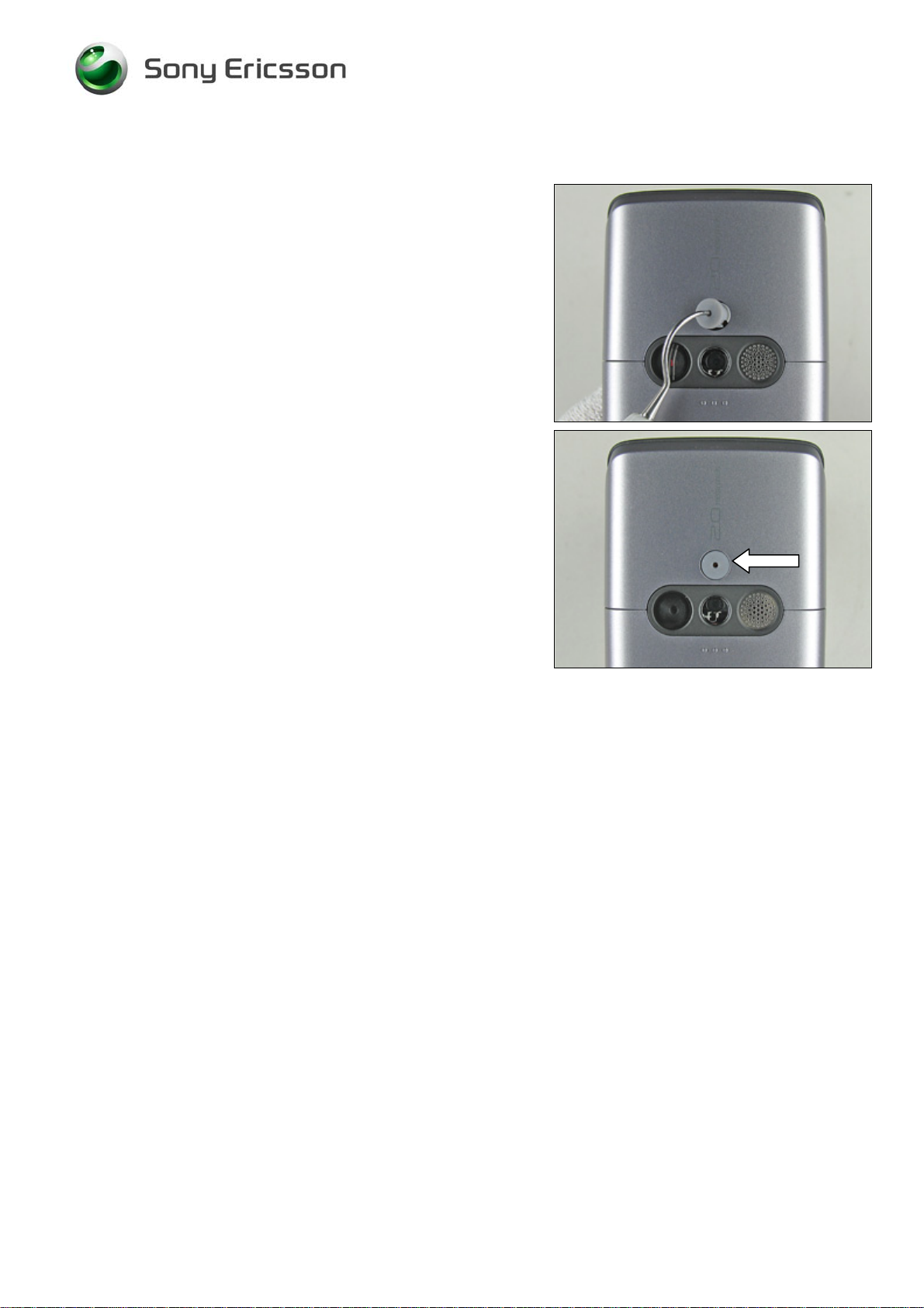
3.14 Water Indicator
REMOVAL
Follow the 2.1.1 – 2.1.5 Disassembly instructions!
Remove the water indicator with a dentist hook.
INSTALLATION
Attach a new water indicator with the tweezers.
Close up picture on a properly mounted water indicator.
Follow the 4.1.1 – 4.1.5 Reassembly instructions!
INSPECTION
Check for water damage on the water indicator with the
battery lid and battery removed!
3/000 21-1/FEA 209 544/109 B
©
Sony Ericsson Mobile Communications AB
29(53)
Page 30

Working Instruction, Mechanical
3.15 Key (Power)
REMOVAL
Follow the 2.1.1 – 2.1.5 Disassembly instructions!
Remove the power key with the tweezers.
INSTALLATION
Mount a new power key into the rear case with the
tweezers.
Follow the 4.1.1 – 4.1.5 Reassembly instructions!
3/000 21-1/FEA 209 544/109 B
©
Sony Ericsson Mobile Communications AB
30(53)
Page 31

Working Instruction, Mechanical
3.16 Key (Volume)
REMOVAL
Follow the 2.1.1 – 2.1.5 Disassembly instructions!
Remove the volume key with the tweezers.
INSTALLATION
Mount a new volume key into the frame with the tweezers.
Follow the 4.1.1 – 4.1.5 Reassembly instructions!
3/000 21-1/FEA 209 544/109 B
©
Sony Ericsson Mobile Communications AB
31(53)
Page 32

Working Instruction, Mechanical
3.17 Key (Music)
REMOVAL
Follow the 2.1.1 – 2.1.5 Disassembly instructions!
Remove the music key with the tweezers.
INSTALLATION
Mount a new music key into the frame with the tweezers.
Follow the 4.1.1 – 4.1.5 Reassembly instructions!
3/000 21-1/FEA 209 544/109 B
©
Sony Ericsson Mobile Communications AB
32(53)
Page 33

Working Instruction, Mechanical
3.18 Key (Cam)
REMOVAL
Follow the 2.1.1 – 2.1.5 Disassembly instructions!
Remove the cam key with the tweezers.
INSTALLATION
Mount a new cam key into the frame with the tweezers.
Check that the cam key is mounted in the right position.
Follow the 4.1.1 – 4.1.5 Reassembly instructions!
3/000 21-1/FEA 209 544/109 B
©
Sony Ericsson Mobile Communications AB
33(53)
Page 34

Working Instruction, Mechanical
3.19 Vibrator
REMOVAL
Follow the 2.1.1 – 2.1.5 Disassembly instructions!
D
O NOT TOUCH THE VIBRATOR CONTACT SPRINGS OR DAMAGE
THE FLYWHEEL
Lift the vibrator straight up with the tweezers.
!
INSTALLATION
Press the vibrator gently to the bottom of the cavity with the
tweezers without touching the contact springs.
Check that the contact springs are in good condition and
that they are not deformed.
Follow the 4.1.1 – 4.1.5 Reassembly instructions!
3/000 21-1/FEA 209 544/109 B
©
Sony Ericsson Mobile Communications AB
34(53)
Page 35

Working Instruction, Mechanical
3.20 Loudspeaker
REMOVAL
Follow the 2.1.1 – 2.1.5 Disassembly instructions!
Release the loudspeaker from one of the two locking
devices.
Remove the loudspeaker with the tweezers.
INSTALLATION
D
O NOT TOUCH THE CONTACT SURFACE
Slide the new loudspeaker into the cavity (under one of the
locking devices) and press gently with your finger and hold
it for a few seconds to secure a god attachment.
!
Make sure that the two locking devices are properly locked.
Follow the 4.1.1 – 4.1.5 Reassembly instructions!
3/000 21-1/FEA 209 544/109 B
©
Sony Ericsson Mobile Communications AB
35(53)
Page 36

Working Instruction, Mechanical
3.21 Cushion (Speaker)
REMOVAL
Follow the 2.1.1 – 2.1.5 Disassembly instructions!
Follow the 3.20 Removal instructions!
Remove the speaker cushion with the tweezers.
INSTALLATION
Attach a new speaker cushion with the tweezers.
Follow the 3.20 Installation instructions!
Follow the 4.1.1 – 4.1.5 Reassembly instructions!
3/000 21-1/FEA 209 544/109 B
©
Sony Ericsson Mobile Communications AB
36(53)
Page 37

Working Instruction, Mechanical
3.22 Sub Assembly Case (Rear)
REMOVAL
Follow the 2.1.1 – 2.1.5 Disassembly instructions!
M
OST OF THE COMPONENTS CAN BE REUSED UNLESS THEY
ARE DAMAGED
INSTALLATION
Don’t forget to install:
1. Key (power), 2. Key (music), 3. Loudspeaker, 4. Cap RF
5. Key (volume), 6. Vibrator, 7. Key (cam)
8. M2 Cover MS (K618), 9. Water indicator
Follow the 4.1.1 – 4.1.5 Reassembly instructions!
!
3/000 21-1/FEA 209 544/109 B
©
Sony Ericsson Mobile Communications AB
37(53)
Page 38

Working Instruction, Mechanical
3.23 System Connector
REMOVAL
Follow the 2.1.1 – 2.1.5 Disassembly instructions!
Remove the system connector by hand.
INSTALLATION
Mount a new system connector with your fingers.
Press the system connector firmly to the bottom of the PBA.
Picture shows a properly mounted system connector.
Follow the 4.1.1 – 4.1.5 Reassembly instructions!
3/000 21-1/FEA 209 544/109 B
©
Sony Ericsson Mobile Communications AB
38(53)
Page 39

Working Instruction, Mechanical
3.24 Main Antenna
REMOVAL
Follow the 2.1.1 – 2.1.5 Disassembly instructions!
Remove the two screws from the main antenna by using the
JCIS bit.
R
EMOVED SCREWS CAN BE REUSED IF THEY AREN’T DAMAGED
!
Release the hook that secures the main antenna by
pushing from the back with the tweezers (or a small
screwdriver) until it becomes loose.
Wiggle the main antenna slightly until it is completely loose
from the frame/PBA.
Main antenna removed.
3/000 21-1/FEA 209 544/109 B
©
Sony Ericsson Mobile Communications AB
39(53)
Page 40

Working Instruction, Mechanical
Main Antenna continued
INSTALLATION
Begin by placing the main antenna against the frame/PBA.
Continue to snap the main antenna to the frame/PBA until it
is completely in place.
Make sure that the main antenna is mounted correctly in the
frame/PBA and that the two hooks (located by the arrows)
are latched.
R
EPLACE THE SCREWS IF THEY ARE DAMAGED
Apply 13 Ncm ± 2 Ncm torque when tightening the two
screws with the JCIS bit.
Follow the 4.1.1 – 4.1.5 Reassembly instructions!
!
3/000 21-1/FEA 209 544/109 B
©
Sony Ericsson Mobile Communications AB
40(53)
Page 41

Working Instruction, Mechanical
3.25 Camera Shield
REMOVAL
Follow the 2.1.1 – 2.1.5 Disassembly instructions!
This part is the camera shield which is to be removed.
Gently release the camera shield with the dentist hook:
Then work your way around the camera shield until it
becomes completely loose.
Remove the camera shield with the tweezers.
INSTALLATION
C
HECK THAT THE CAMERA SHIELD IS IN ITS PROPER POSITION
Install a new camera shield with your fingers.
3/000 21-1/FEA 209 544/109 B
©
Sony Ericsson Mobile Communications AB
!
41(53)
Page 42

Working Instruction, Mechanical
Camera Shield continued
Make sure that the camera shield is in its right position.
Note the slit on the side by the arrow before you push it to
the bottom.
Follow the 4.1.1 – 4.1.5 Reassembly instructions!
3/000 21-1/FEA 209 544/109 B
©
Sony Ericsson Mobile Communications AB
42(53)
Page 43

Working Instruction, Mechanical
3.26 Camera, 2M Pixel
REMOVAL
Follow the 2.1.1 – 2.1.5 Disassembly instructions!
Follow the 3.25 Removal instructions!
N
EVER TOUCH THE CAMERA LENS
Start by pressing the mega camera removal tool over the
camera all the way to the bottom.
!
If necessary wiggle the mega camera removal tool slightly
side to side and at the same time pull the camera straight
up (together with the tool) from the socket.
Remove the camera from the mega camera removal tool.
INSTALLATION
Notice the small notch in the camera socket.
3/000 21-1/FEA 209 544/109 B
©
Sony Ericsson Mobile Communications AB
43(53)
Page 44

Working Instruction, Mechanical
Camera, 2M Pixel continued
N
EVER TOUCH THE CAMERA LENS
Press gently on the top of the camera until it snaps into
place.
!
Make sure that the camera is in its right position (to the
bottom of the socket and properly locked).
Mount the camera shield over the camera with your fingers.
Follow the 3.25 Installation instructions!
Follow the 4.1.1 – 4.1.5 Reassembly instructions!
3/000 21-1/FEA 209 544/109 B
©
Sony Ericsson Mobile Communications AB
44(53)
Page 45

Working Instruction, Mechanical
3.27 Label
REMOVAL
Follow the 2.1.1 Disassembly instructions!
• Read the old label and/or write the information into the
“Label make” program before removal
• Note the position of the label before removal
• Heat up the label by using hot air, if needed.
• Carefully remove the label without causing scratches
• If there still are residues, clean the surface with isopropyl
alcohol
INSTALLATION
• Check that the proper label format is loaded in the Zebra
printer.
• Write a new label by using the program “Label make”
and check that the printing is OK.
• Take the new label and place it onto the frame as in the
adjacent picture.
O
NE LABEL ONLY IS ALLOWED
Follow the 4.1.5 Reassembly instructions!
!
3/000 21-1/FEA 209 544/109 B
©
Sony Ericsson Mobile Communications AB
45(53)
Page 46

Working Instruction, Mechanical
4 Reassembly
After replacing a part being listed in Replacements, the instruction of that section usually ends by
directing you to this Reassembly section with a specification of the instructions you have to carry out
in order to reassemble the phone.
REPLACEMENTS
Start
Contents
page
DISASSEMBLY
4.1 Overview
REASSEMBLY
Done
The reassembly is done in the following sequence:
1. Sub Assembly Case (Rear)
2. Key (Main)
3. Sub Assembly Case (Front)
4. Cover (Rear)
5. Battery (a) & Sub Assembly Lid (Battery) (b)
3/000 21-1/FEA 209 544/109 B
©
Sony Ericsson Mobile Communications AB
46(53)
Page 47

Working Instruction, Mechanical
4.1.1 Sub Assembly Case (Rear)
B
E MOST CAREFUL WITH THE MUSIC KEY BUTTON
(2) ,
KEY BUTTON
BUTTON
CASE SINCE THE KEY BUTTONS EASILY CAN BE SQUEEZED AND
DAMAGED
(4)
!
VOLUME KEY BUTTON
WHEN THE FRAME/PBA IS INSTALLED IN THE REAR
(3)
AND THE CAM KEY
Start like this before the installation of the rear case.
(1),
POWER
Push the frame/PBA unit into the cavity for the system
connector on the rear case.
If the rubber keys obstruct the passage of the frame/PBA,
gently push the rubber keys into place by using the
tweezers or the dentist hook.
Gently press the frame/PBA into the rear case.
Make sure that the frame/PBA is securely fastened to the
rear case.
Frame/PBA properly installed inside the rear case.
3/000 21-1/FEA 209 544/109 B
©
Sony Ericsson Mobile Communications AB
47(53)
Page 48

Working Instruction, Mechanical
4.1.2 Key (Main)
Mount the main key by hand.
Make sure that the main key is placed properly on the four
guiding pins.
3/000 21-1/FEA 209 544/109 B
©
Sony Ericsson Mobile Communications AB
48(53)
Page 49

Working Instruction, Mechanical
4.1.3 Sub Assembly Case (Front)
S
TART THE ASSEMBLY FROM THE BOTTOM OF THE PHONE
Place the front case over the phone.
Sometimes the main key stays in the front case, sometimes
it falls out.
Just be careful and align the front case with the main key.
!
Snap the front case and the phone together …
… along both sides.
Check that there are no gaps along the sides.
If there still is a gap somewhere, gently press the two
halves together with your fingers.
Apply 20 Ncm ± 2 Ncm torque by tightening the four
screws using torx bit no. 6.
R
EPLACE THE SCREWS IN CASE THEY ARE DAMAGED
!
3/000 21-1/FEA 209 544/109 B
©
Sony Ericsson Mobile Communications AB
49(53)
Page 50

Working Instruction, Mechanical
4.1.4 Cover (Rear)
I
T IS MOST IMPORTANT TO START THE ASSEMBLY OF THE REAR
COVER TOWARDS THE TOP OF THE PHONE
!
Snap the rear cover to the phone by starting at the top.
BE MOST CAREFUL WITH THE PLASTIC LOCKS SINCE THEY
EASILY MIGHT BREAK
.
First press inwards
and then downwards to lock the rear
cover.
Continue and do they same thing on the opposite side.
3/000 21-1/FEA 209 544/109 B
©
Sony Ericsson Mobile Communications AB
50(53)
Page 51

Working Instruction, Mechanical
Cover (Rear) continued
Check that the rear cover is properly mounted, with no gaps
along the sides.
If there still is a gap somewhere, gently press the two
halves together with your fingers.
3/000 21-1/FEA 209 544/109 B
©
Sony Ericsson Mobile Communications AB
51(53)
Page 52

Working Instruction, Mechanical
4.1.5 Battery & Sub Assembly Lid (Battery)
Put the top of the battery into the battery compartment.
Slide the battery towards the top and press at the bottom to
secure its position.
Place the battery lid on top of the battery and slide it
towards the top of the phone.
Push with your fingers at the bottom of the battery lid until it
becomes completely closed (no gap).
3/000 21-1/FEA 209 544/109 B
©
Sony Ericsson Mobile Communications AB
52(53)
Page 53

Working Instruction, Mechanical
5 Revision history
Rev. Date Changes / Comments
A 2006-06-23 First release
B 2006-06-28 New Working Instruction Directive
3/000 21-1/FEA 209 544/109 B
©
Sony Ericsson Mobile Communications AB
53(53)
 Loading...