

Page 1

K600/K608/V600 Working Instructions - mechanical
Working Instructions - mechanical
Applicable for K600, K608 & V600
CONTENTS
1 Read this first!........................................................................................ 2
2 Introduction ............................................................................................ 3
3 Repair actions........................................................................................ 4
3.1
Battery Lid & Battery ..................................................................................6
3.2
Rear Case sub ass’y..................................................................................8
3.3
Front Case sub ass’y................................................................................10
3.4
Keypad.....................................................................................................11
3.5
Key Flex ass’y..........................................................................................12
3.6
LCD…. .....................................................................................................14
3.7
Receiver...................................................................................................16
3.8
Frame & Camera Front ............................................................................17
3.9
Antenna Frame ass’y ...............................................................................19
3.10 Flash Light................................................................................................20
3.11 Camera Grommet.....................................................................................21
3.12 Videophone Key.......................................................................................21
3.13 Volume Key..............................................................................................22
3.14 Internet Key..............................................................................................22
3.15 Microphone ..............................................................................................23
3.16 Camera, rear............................................................................................23
3.17 Liquid Intrusion Indicator..........................................................................24
3.18 Cover USB ...............................................................................................25
3.19 Vibrator ass’y ...........................................................................................26
3.20 Loudspeaker ............................................................................................27
3.21 Cover & Bearing, camera rear..................................................................28
3.22 Magnet .....................................................................................................29
3.23 Cap RF (external antenna).......................................................................30
3.24 Co-brand inlay..........................................................................................31
4 Label ......................................................................................................32
5 Revision History ...................................................................................33
3/00021-1/FEA 209 544/98A
Company Internal
©
Sony Ericsson Mobile Communications AB
Page 2
K600/K608/V600 Working Instructions - mechanical
1 Read this first!
After reading section 2 ‘Introduction’ and the first page of section 3 ‘Repair Actions’,
do as follows when a mechanical part needs to be replaced:
• Search for the part name on the contents page and go to the page number
where the instruction is found
• Disassemble the phone as far as needed by moving to the instructions stated as e.g.
Follow the Removal instructions of sections 3.1 – 3.6
• Carry out the actual repair action as described
• Assemble the phone by moving to the instructions stated as e.g.
Follow the Assembly instructions of sections 3.6 – 3.1 (pls. note the reverse order)
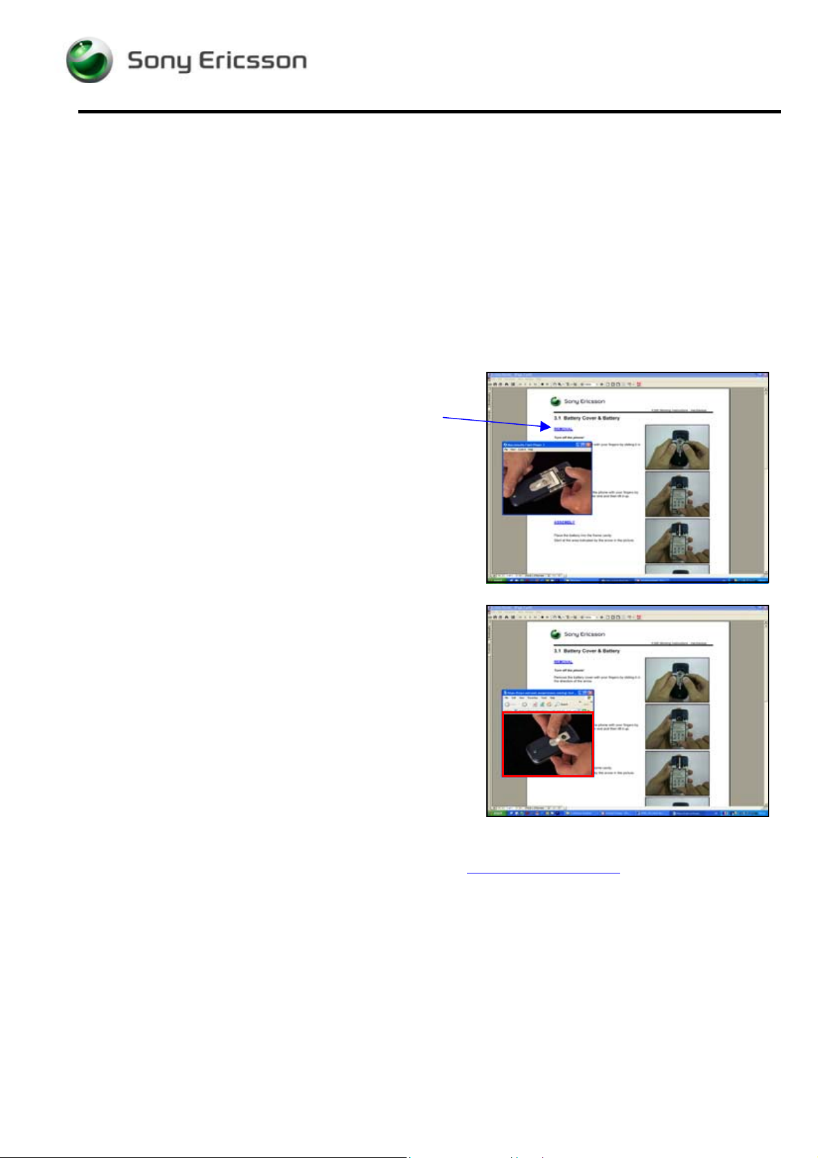
When watching the document off-line (after downloading
and extracting the ZIP-file), most of the Removal and
Assembly headings are blue-colored and underlined.
By clicking on such a heading, a Flash Player window
opens, showing a video clip of the removal/assembly.
The flash movie can be controlled from the keyboard by
holding down the Ctrl-key and pressing another key as
follows:
- Start and Stop: Ctrl – Enter
- Rewind to start position: Ctrl – R
- Move one small step forward: Ctrl – right arrow
- Move one small step back: Ctrl – left arrow
If your computer is set up to show Flash movies in an
Internet Explorer window, the movie will most likely be full
size, resulting in poor picture quality.
To shrink the video window to its proper size, drag the
bottom right corner of the Internet Explorer window until
the movie is shown without blurs and edges, which occurs
when the movie window is approx. 12 x 9 cm (indicated by
the red frame in the adjacent picture).
However, it is recommended to have your computer set up
to have the Flash movies played by the Flash Player
application.
NOTE! Flash Player ver. 6 or later must be installed on the computer.
The Flash Player can be downloaded free of charge from www.macromedia.com
.
3/00021-1/FEA 209 544/98A
Company Internal
©
Sony Ericsson Mobile Communications AB
2(33)
Page 3
K600/K608/V600 Working Instructions - mechanical
2 Introduction
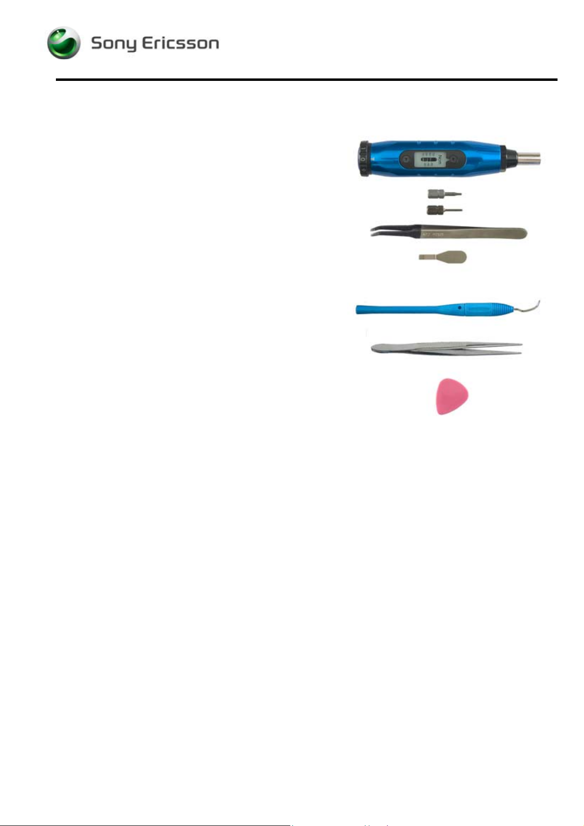
SPECIAL TOOLS
No new special tools are introduced but a few other
Sony Ericsson tools are required:
• NTZ 112 459 Torque screwdriver (or equivalent) set
to 20 Ncm ± 6% and 11 Ncm ± 2 Ncm
• NTZ 112 288 Torx bit no. 6 (for 20 Ncm)
• NTZ 112 1052 Phillips bit (for 11 Ncm)
• NTZ 112 521 Flexfilm assembly tool
• NTZ 112 302/2 Front opening tool
STANDARD TOOLS
The following tools have to be locally purchased:
• Dentist hook
• Blunt pair of tweezers
• Guitar pick
ESD EQUIPMENT
Protect the phone from ESD damages whenever it has been opened by using:
• ESD-gloves (cotton gloves)
• ESD-wristband
ADHESIVES
Use a dentist hook or a blunt pair of tweezers to remove old adhesives.
If necessary, clean the surface with isopropyl alcohol before attaching new adhesives.
CAUTIONS
• Keep all contact surfaces clean, no dirt or hand grease!
• Be careful when using tools like the dentist hook, tweezers, opening tools, guitar pick etc.
to avoid scratches or damages to the exterior and interior parts of the phone!
• Be careful not to damage the contact springs on parts like the microphone and vibrator!
• Remember to remove the protection foils on new parts such as the front case and
the LCD!
• Never touch the display glass!
• Use air blow equipment to keep the front window and display module dust free!
3/00021-1/FEA 209 544/98A
Company Internal
©
Sony Ericsson Mobile Communications AB
3(33)
Page 4
K600/K608/V600 Working Instructions - mechanical
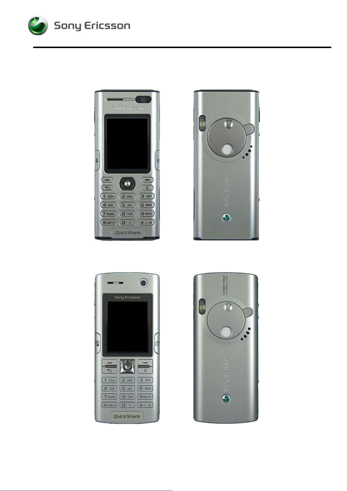
3 Repair actions
K600
K608
3/00021-1/FEA 209 544/98A
Company Internal
©
Sony Ericsson Mobile Communications AB
4(33)
Page 5
K600/K608/V600 Working Instructions - mechanical
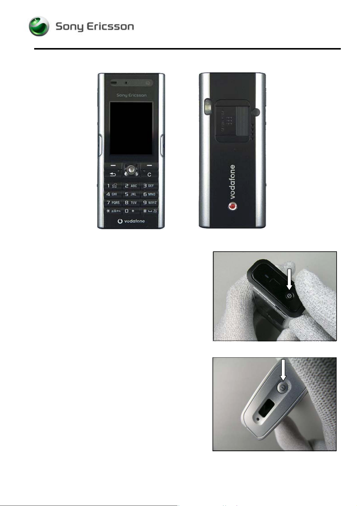
V600
PRECAUTIONARY ACTIONS
Press the On/Off-button to turn the phone off.
3/00021-1/FEA 209 544/98A
Company Internal
©
Sony Ericsson Mobile Communications AB
5(33)
Page 6
K600/K608/V600 Working Instructions - mechanical
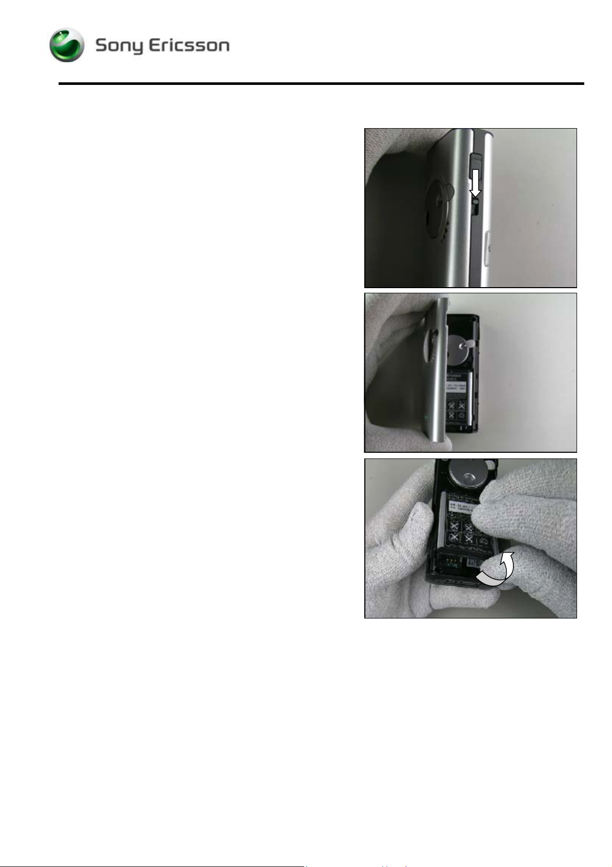
3.1 Battery Lid & Battery
REMOVAL
Push the two locking knobs downwards.
Gently fold up the battery lid and remove it.
Lift up the battery and remove it.
3/00021-1/FEA 209 544/98A
Company Internal
©
Sony Ericsson Mobile Communications AB
6(33)
Page 7
K600/K608/V600 Working Instructions - mechanical
Battery Lid & Battery continued
ASSEMBLY
Put the battery in the battery compartment.
.
Attach the battery lid by starting at the side of the volume
keys and then fold it down.
Lock the lid with the two locking knobs.
3/00021-1/FEA 209 544/98A
Company Internal
©
Sony Ericsson Mobile Communications AB
7(33)
Page 8
K600/K608/V600 Working Instructions - mechanical
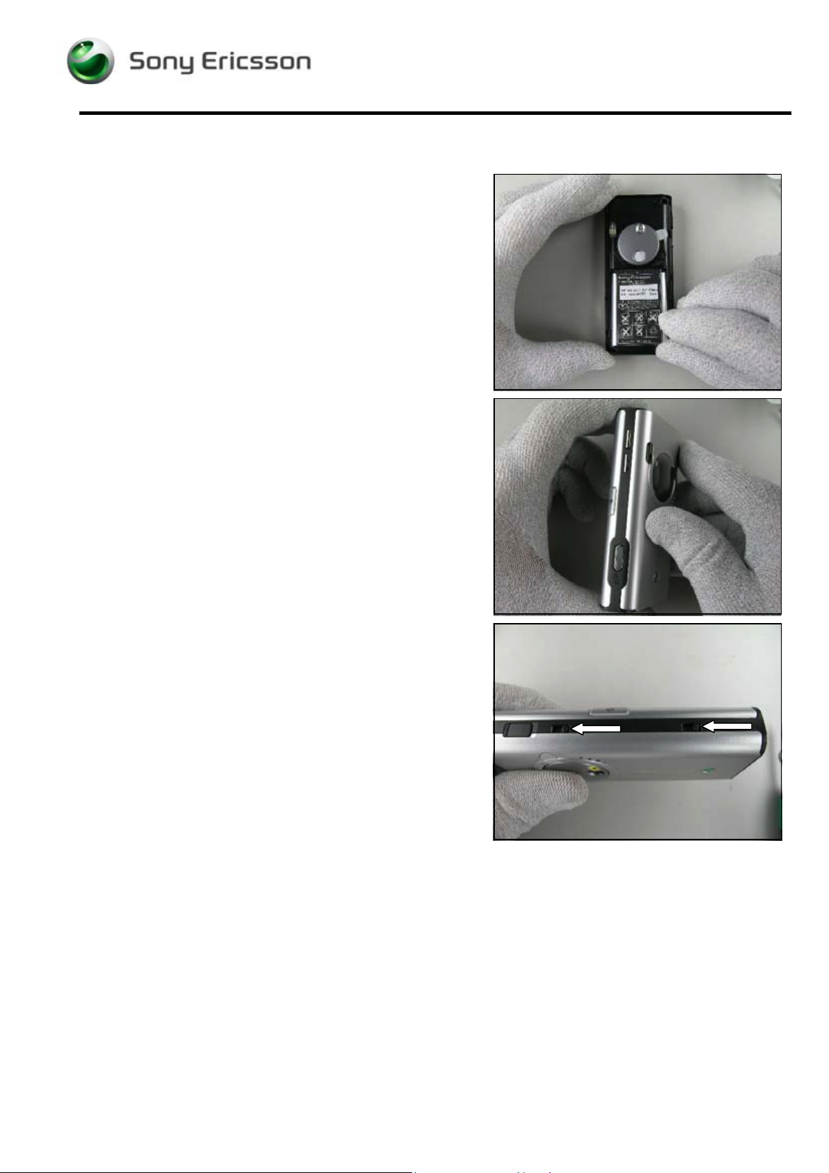
3.2 Rear Case sub ass’y
REMOVAL
Follow the Removal Instructions of section 3.1
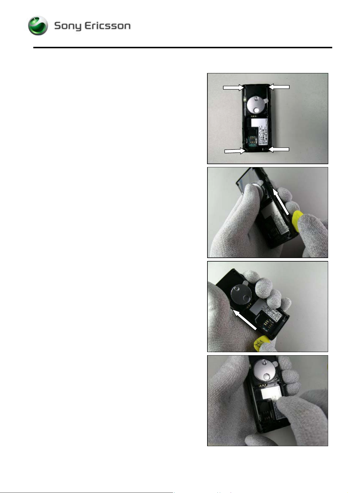
This picture shows the screw positions of K600 which
are the same for K608 and V600!
Remove the four screws using torx bit no. 6.
Removed screws cannot be used and must be scrapped!
Insert the guitar pick between the front case and the rear
case and release the rear case by sliding the guitar pick to
unsnap the snap hooks.
The USB cover might fall out during this procedure!
Do the same thing on the opposite side of the phone!
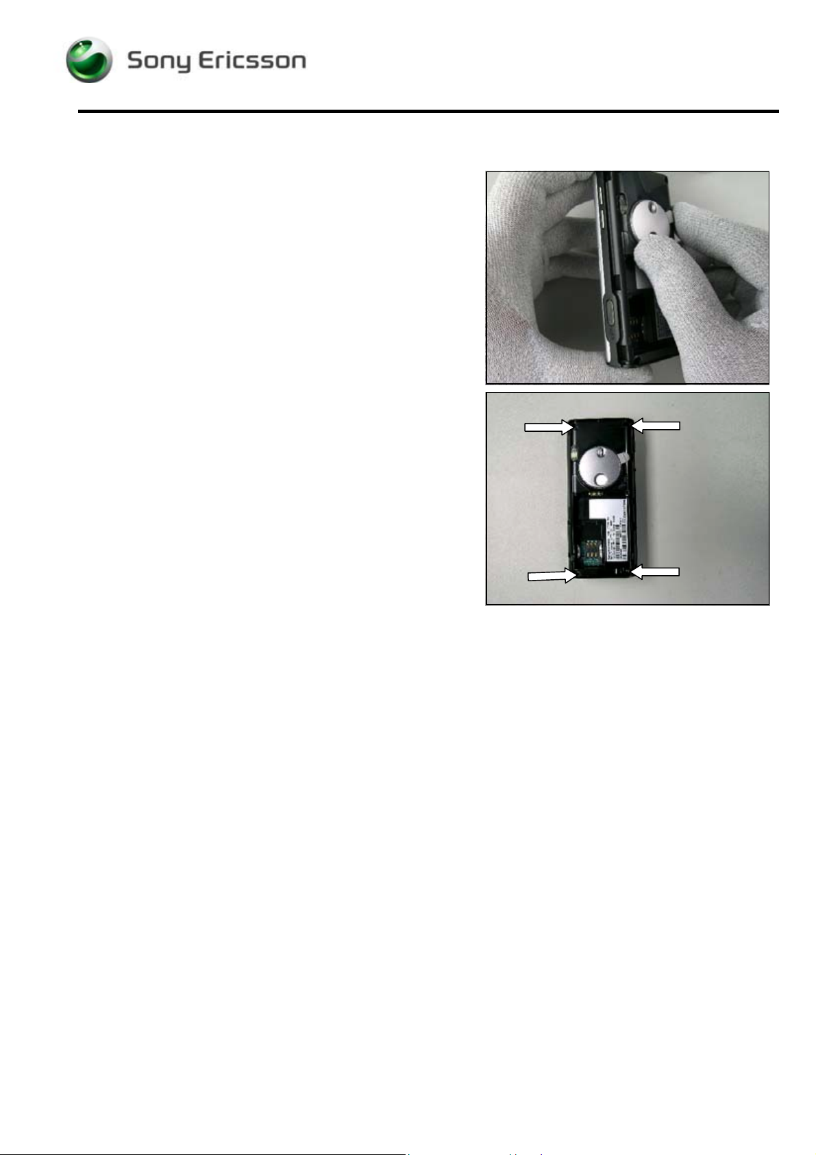
Gently lift the rear case up and remove it.
3/00021-1/FEA 209 544/98A
Company Internal
©
Sony Ericsson Mobile Communications AB
8(33)
Page 9
K600/K608/V600 Working Instructions - mechanical
Rear case sub ass’y continued
ASSEMBLY
Position the rear case onto the front case and gently push
to make them snap together.
Tighten four new screws using 20 Ncm torque with torx bit
no. 6.
Follow the Assembly instructions of section 3.1
3/00021-1/FEA 209 544/98A
Company Internal
©
Sony Ericsson Mobile Communications AB
9(33)
Page 10
K600/K608/V600 Working Instructions - mechanical
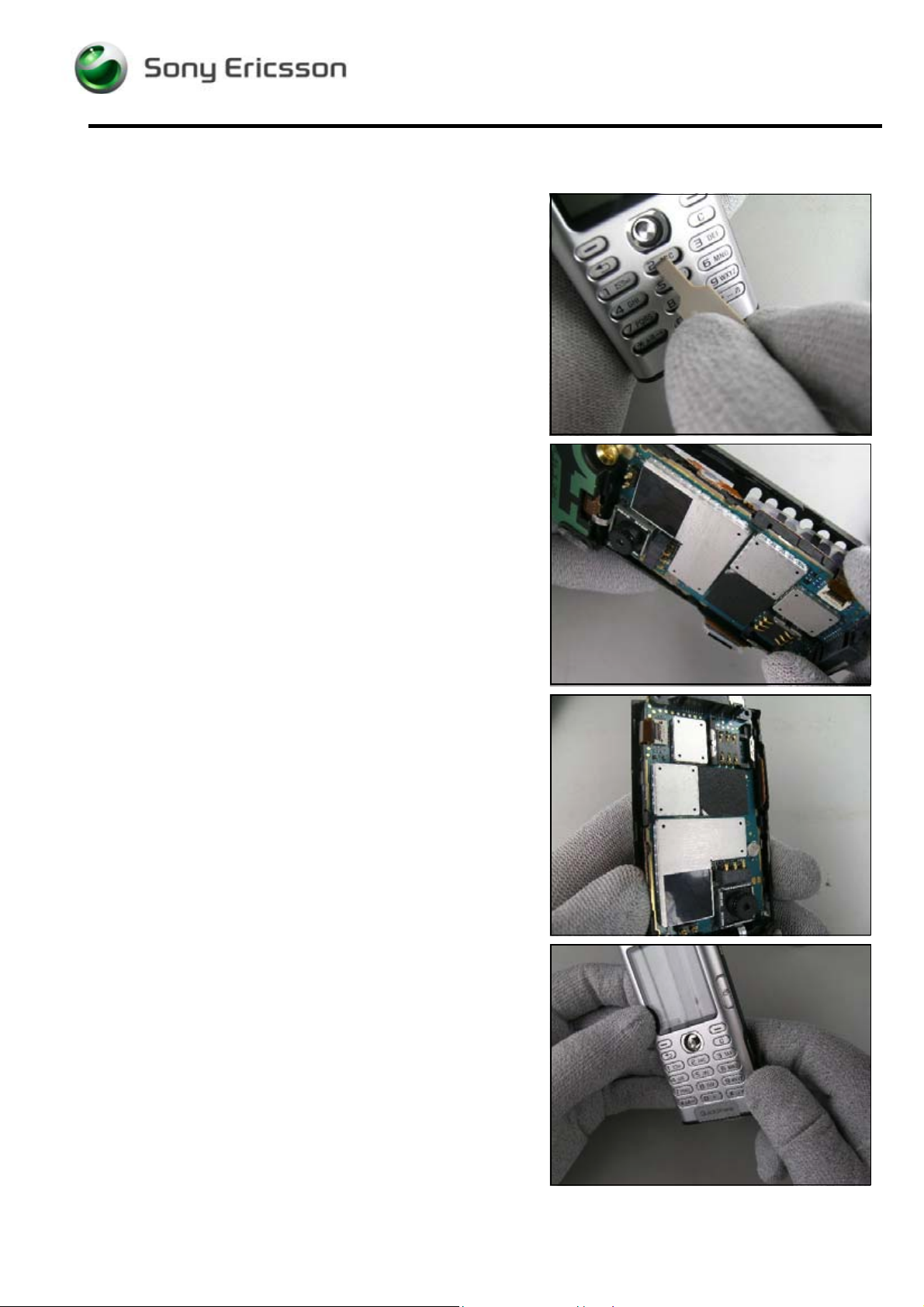
3.3 Front Case sub ass’y
REMOVAL
Follow the Removal instructions of sections 3.1–3.2
Press with the Front Opening Tool on the digit ‘2’ of the
keypad to release the PCB.
Separate the PCB from the front case.
ASSEMBLY
Make sure that all components inside the front case are
in their proper places!
Place the PCB into the side with the volume key first.
Gently push the PCB onto the front case to make them
snap together.
Follow the Assembly instructions of 3.2 - 3.1
3/00021-1/FEA 209 544/98A
Company Internal
©
Sony Ericsson Mobile Communications AB
10(33)
Page 11

K600/K608/V600 Working Instructions - mechanical
3.4 Keypad
REMOVAL
Follow the Removal instructions of sections 3.1 – 3.3
Fold up the keypad and insert the Flexfilm Assembly Tool
as shown in the picture.
Release the joystick button by carefully bending upwards
and then removing the keypad including the joystick
button.
If required, remove the joystick button from the keypad.
ASSEMBLY
If required, first attach the joystick button to the keypad.
Attach the joystick button by carefully pressing it onto the
joystick switch and then fold down the keypad.
Follow the Assembly instructions of sections 3.3 – 3.1
3/00021-1/FEA 209 544/98A
Company Internal
©
Sony Ericsson Mobile Communications AB
11(33)
Page 12

K600/K608/V600 Working Instructions - mechanical
3.5 Key Flex ass’y
REMOVAL
Follow the Removal instructions of sections 3.1 – 3.4
The side buttons of key flex are located as indicated by the
arrows and are attached with adhesives.
Use the dentist hook, or tweezers to release the side
buttons of the key flex.
.
The ZIF connector functions like this:
Carefully open the ZIF connector and gently remove the
key flex with the tweezers.
3/00021-1/FEA 209 544/98A
Company Internal
©
Sony Ericsson Mobile Communications AB
12(33)
Page 13

K600/K608/V600 Working Instructions - mechanical
Key Flex ass’y continued
ASSEMBLY
The camera key switch is located as indicated by the
arrow.
Slide the camera key switch down into the two supports of
the frame.
Fold down the flex film over the frame and attach the two
side keys.
The ZIF Connector functions like this:
Use the Flexfilm Assembly Tool to connect the key flex
connector to the PCB.
Follow the Assembly instructions of sections 3.4 – 3.1
3/00021-1/FEA 209 544/98A
Company Internal
©
Sony Ericsson Mobile Communications AB
13(33)
Page 14

K600/K608/V600 Working Instructions - mechanical
3.6 LCD
REMOVAL
Follow the Removal instructions of sections 3.1 – 3.5
There is a gap between the LCD and the frame which is
located as indicated by the arrow.
Put the dentist hook in this gap and raise the LCD from the
frame and turn it upside down.
Remove the protection sheet by using tweezers.
The protection sheet cannot be reused!
The ZIF connector functions like this:
Use the Flexfilm Assembly Tool to open the ZIF connector
of the LCD on the PCB and then remove the LCD.
3/00021-1/FEA 209 544/98A
Company Internal
©
Sony Ericsson Mobile Communications AB
14(33)
Page 15

K600/K608/V600 Working Instructions - mechanical
LCD continued
ASSEMBLY
The ZIF connector functions like this:
.
Gently slide the flex film into the ZIF connector and close
the ZIF Connector using the Flexfilm Assembly Tool.
Attach a new protection sheet using the Flexfilm Assembly
Tool.
Turn the LCD and press it gently into its frame.
Follow the Assembly instructions of sections 3.5 – 3.1
3/00021-1/FEA 209 544/98A
Company Internal
©
Sony Ericsson Mobile Communications AB
15(33)
Page 16

K600/K608/V600 Working Instructions - mechanical
3.7 Receiver
REMOVAL
Follow the Removal instructions of sections 3.1 – 3.6
Disconnect the receiver connector by using the dentist
hook.
Place the dentist hook as shown in the picture and remove
the receiver.
ASSEMBLY
Connect the receiver connector to the PCB.
Gently press the receiver into the frame cavity.
Follow the Assembly instructions of sections 3.6 – 3.1
3/00021-1/FEA 209 544/98A
Company Internal
©
Sony Ericsson Mobile Communications AB
16(33)
Page 17

K600/K608/V600 Working Instructions - mechanical
3.8 Frame & Camera Front
REMOVAL
Follow the Removal instructions of sections 3.1 – 3.7
Remove the three screws using the Phillips bit.
Removed screws cannot be reused and must be
scrapped!
.
Insert the Front Opening Tool into the gap between the
BTB connector of the camera front and the PCB.
Disconnect the BTB connector by pushing the Front
Opening Tool upwards.
.
Release the frame by unsnapping four snap hooks,
where this picture shows the 1
st
snap hook.
nd
2
snap hook.
3/00021-1/FEA 209 544/98A
Company Internal
©
Sony Ericsson Mobile Communications AB
17(33)
Page 18

K600/K608/V600 Working Instructions - mechanical
Frame & Camera Front continued
rd
3
snap hook.
th
4
snap hook.
Remove the frame and release the camera front from the
frame.
ASSEMBLY
Use the Flex Film Assembly Tool or your fingers to
connect the BTB connector of the camera front.
Place the frame on the PCB and make sure that the
camera front is in correct position on the frame.
Use your fingers to snap the frame to the PCB.
Tighten three new screws using 11 Ncm torque with the
Phillips bit.
Follow the Assembly instructions of sections 3.7 – 3.1
3/00021-1/FEA 209 544/98A
Company Internal
©
Sony Ericsson Mobile Communications AB
18(33)
Page 19

K600/K608/V600 Working Instructions - mechanical
3.9 Antenna Frame ass’y
REMOVAL
Follow the Removal instructions of sections 3.1 – 3.8
Release the antenna frame by unsnapping the three snap
hooks and then turn the antenna frame upside down.
. The ZIF connector functions like this:
Use a dentist hook to open the ZIF connector and remove
the antenna frame.
ASSEMBLY
Open the ZIF connector, insert the flex film and close the
connector using the Flexfilm Assembly Tool.
Turn the antenna frame to its normal position and use your
fingers to snap the three hooks of the antenna frame to the
PCB.
Follow the Assembly instructions of sections 3.8 – 3.1
3/00021-1/FEA 209 544/98A
Company Internal
©
Sony Ericsson Mobile Communications AB
19(33)
Page 20

K600/K608/V600 Working Instructions - mechanical
3.10 Flash Light
REMOVAL
Follow the Removal instructions of sections 3.1 – 3.9
.
If the flash light packing is damaged, remove the packing
from the flash light using tweezers.
The packing cannot be reused.
Slightly press on the edge of the antenna frame and
simultaneously press on the top of flash light to remove it.
ASSEMBLY
Put the flash light into the antenna frame and gently push
the flash light until it snaps into the antenna frame.
If a new packing is required, attach a new one by using
tweezers.
Follow the Assembly instructions of sections 3.9 – 3.1
3/00021-1/FEA 209 544/98A
Company Internal
©
Sony Ericsson Mobile Communications AB
20(33)
Page 21

K600/K608/V600 Working Instructions - mechanical
3.11 Camera Grommet
REMOVAL
Follow the Removal instructions of sections 3.1 – 3.8
Use your fingers to remove the camera grommet without
touching the camera lens.
ASSEMBLY
Use your fingers to put the camera grommet onto the
camera.
Follow the Assembly instructions of sections 3.8 – 3.1
.
3.12 Videophone Key
REMOVAL
Follow the Removal instructions of sections 3.1 – 3.3
Remove the videophone key by using tweezers.
ASSEMBLY
Use your fingers or tweezers to attach the videophone key
inside the front case.
Make sure that the videophone key is in its proper
position.
Follow the Assembly instructions of sections 3.3 – 3.1
3/00021-1/FEA 209 544/98A
Company Internal
©
Sony Ericsson Mobile Communications AB
21(33)
Page 22

K600/K608/V600 Working Instructions - mechanical
3.13 Volume Key
REMOVAL
Follow the Removal instructions of sections 3.1 – 3.3
Remove the volume key by using the dentist hook or
tweezers.
ASSEMBLY
Use your fingers or tweezers to attach the volume key
inside the front case.
Make sure that the volume key is in its proper position.
Follow the Assembly instructions of sections 3.3 – 3.1
3.14 Internet Key
REMOVAL
Follow the Removal instructions of sections 3.1 – 3.3
Remove the Internet key by using tweezers.
ASSEMBLY
Use your fingers or tweezers to attach the Internet key
inside the front case.
Make sure that the internet key is in its proper position.
Follow the Assembly instructions of sections 3.3 – 3.1
3/00021-1/FEA 209 544/98A
Company Internal
©
Sony Ericsson Mobile Communications AB
22(33)
Page 23

K600/K608/V600 Working Instructions - mechanical
3.15 Microphone
REMOVAL
Follow the Removal instructions of sections 3.1 – 3.3
Remove the microphone with a dentist hook.
ASSEMBLY
Place a microphone into the frame cavity.
Press the microphone gently to the bottom of the cavity.
Follow the Assembly instructions of sections 3.3 – 3.1
.
3.16 Camera, rear
REMOVAL
Follow the Removal instructions of sections 3.1 – 3.2
Remove the camera with a dentist hook or with your
fingers by lifting it straight up.
ASSEMBLY
Position the camera so that the guiding pin on the camera
goes into the guiding hole of the socket on the PCB.
Use your fingers to mount the camera.
Follow the Assembly instructions of sections 3.2 – 3.1
3/00021-1/FEA 209 544/98A
Company Internal
©
Sony Ericsson Mobile Communications AB
23(33)
Page 24

K600/K608/V600 Working Instructions - mechanical
3.17 Liquid Intrusion Indicator
REMOVAL & ASSEMBLY
Follow the Removal instructions of sections 3.1 – 3.2
Notice the liquid intrusion indicator position on the frame.
Remove the liquid intrusion indicator with a dentist hook.
Clean the frame surface with isopropyl alcohol before
attaching the new indicator.
Never reuse a liquid intrusion indicator.
.
This picture shows a water activated liquid intrusion
indicator.
Follow the Assembly instructions of sections 3.2 – 3.1
3/00021-1/FEA 209 544/98A
Company Internal
©
Sony Ericsson Mobile Communications AB
24(33)
Page 25

K600/K608/V600 Working Instructions - mechanical
3.18 Cover USB
REMOVAL & ASSEMBLY
Follow the Removal instructions of sections 3.1 – 3.2
Remove and mount the USB cover by using tweezers,
in the rear case for K600 and K608,
and in the front case for V600.
Follow the Assembly instructions of sections 3.2 – 3.1
3/00021-1/FEA 209 544/98A
Company Internal
©
Sony Ericsson Mobile Communications AB
25(33)
Page 26

K600/K608/V600 Working Instructions - mechanical
3.19 Vibrator ass’y
REMOVAL
Follow the Removal instructions of sections 3.1 – 3.2
Do not lift the vibrator by the flywheel!
Raise the vibrator from its position with the dentist hook
and then gently lift it upwards to remove.
ASSEMBLY
Do not press on the vibrator’s flywheel!
Put the vibrator in the cavity and gently press it into the
bottom of the cavity by using tweezers.
Follow the Assembly instructions of sections 3.2 – 3.1
3/00021-1/FEA 209 544/98A
Company Internal
©
Sony Ericsson Mobile Communications AB
26(33)
Page 27

K600/K608/V600 Working Instructions - mechanical
3.20 Loudspeaker
REMOVAL
Follow the Removal instructions of sections 3.1 – 3.2
Put the dentist hook underneath the loudspeaker and
remove it by gently lifting upwards.
Clean the surface with isopropyl alcohol.
ASSEMBLY
Always attach a new speaker cushion in the cavity.
Put the loudspeaker into the cavity and use your fingers to
gently press on the loudspeaker to secure that it becomes
fixed.
Follow the Assembly instructions of sections 3.2 – 3.1
3/00021-1/FEA 209 544/98A
Company Internal
©
Sony Ericsson Mobile Communications AB
27(33)
Page 28

K600/K608/V600 Working Instructions - mechanical
3.21 Cover & Bearing, camera rear
REMOVAL
Follow the Removal instructions of sections 3.1 – 3.2
To replace just the cover:
Loosen the screw in the middle using the Phillips bit and
remove the cover from the opposite side
To replace just the bearing:
Remove the screw and then the bearing by using
tweezers.
ASSEMBLY
Put the new or existing cover in the position shown in the
picture.
If just the cover was replaced or removed, there should be
no need to adjust the position of the bearing.
If the bearing was replaced or removed, it should be
mounted in the position shown in the picture.
Tighten the screw using 11 Ncm torque with the Phillips
bit.
Follow the Assembly instructions of sections 3.2 – 3.1
3/00021-1/FEA 209 544/98A
Company Internal
©
Sony Ericsson Mobile Communications AB
28(33)
Page 29

K600/K608/V600 Working Instructions - mechanical
3.22 Magnet
REMOVAL
Follow the Removal instructions of sections 3.1 – 3.2 &
3.21
Remove the magnet by using the dentist hook or
tweezers.
Magnets cannot be reused and must be scrapped!
ASSEMBLY
Clean the cover surface with isopropyl alcohol.
The magnet has a red line on one side, which is shown by
the arrow.
Position the magnet with the red line facing upwards and
away from the aperture of the camera cover.
Press gently with the tweezers on the magnet for a few
seconds to secure that the magnet has become fixed.
Follow the Assembly instructions of sections 3.21 &
3.2 – 3.1
3/00021-1/FEA 209 544/98A
Company Internal
©
Sony Ericsson Mobile Communications AB
29(33)
Page 30

K600/K608/V600 Working Instructions - mechanical
3.23 Cap RF (external antenna)
REMOVAL & ASSEMBLY
Remove the cap with the dentist hook.
Mount the new cap with your fingers.
This picture shows where the cap RF is located on K600.
This picture shows where the cap RF is located on K608.
This picture shows where the cap RF is located on V600.
3/00021-1/FEA 209 544/98A
Company Internal
©
Sony Ericsson Mobile Communications AB
30(33)
Page 31

K600/K608/V600 Working Instructions - mechanical
3.24 Co-brand inlay
REMOVAL & ASSEMBLY
Gently remove the co-brand label with the dentist hook.
Do not reuse a co-brand label.
Clean the surface of the cavity with isopropyl alcohol.
Attach the new label by using tweezers or with your fingers
and keep the pressure on the label for a few seconds to
secure that it has become fixed.
3/00021-1/FEA 209 544/98A
Company Internal
©
Sony Ericsson Mobile Communications AB
31(33)
Page 32

K600/K608/V600 Working Instructions - mechanical
4 Label
TOOLS
• Hot air flow solder station
• Blunt pair of tweezers
• Zebra printer and computer
INSTRUCTION
This instruction should be used when exchanging an old
label or assembling a new one.
Note the position of the label before removal!
One label only is allowed on the frame!
• Read the old label and/or write the information into the
“Labelmake” program.
• Heat up the label with a hot air flow solder station, if
needed.
• Carefully remove the label and make sure that all
residues are gone.
If necessary, clean the surface with isopropyl alcohol.
Do not scratch the frame.
• Check that the right label format is loaded in the Zebra
printer.
• Write a new label by using the program “Labelmake”.
Check that the printing is ok.
• Take the new label and place it onto the frame as in the
picture.
Make sure the label is placed in its proper position.
3/00021-1/FEA 209 544/98A
Company Internal
©
Sony Ericsson Mobile Communications AB
32(33)
Page 33

K600/K608/V600 Working Instructions - mechanical
5 Revision History
Rev. Date Changes / Comments
A 2005-06-29 Initial release
3/00021-1/FEA 209 544/98A
Company Internal
©
Sony Ericsson Mobile Communications AB
33(33)
 Loading...