

Page 1

Application Note
Dual SIM connection
Page 2

CE
The product described in this manual conforms to the TTE directive 91/263/EEC and EMC directive
89/336/EEC. The product fulfils the requirements according to ETS 300 342-1.
The information contained in this document is the proprietary information of Sony Ericsson Mobile
Communications. The contents are confidential and any disclosure to persons other than the officers,
employees, agents or subcontractors of the owner or licensee of this document, without the prior written
consent of Sony Ericsson Mobile Communications, is strictly prohibited.
Further, no portion of this publication may be reproduced, stored in a retrieval system, or transmitted in
any form or by any means, electronic or mechanical, including photocopying and recording, without the
prior written consent of Sony Ericsson Mobile Communications, the copyright holder.
First edition (August 2003)
Sony Ericsson Mobile Communications. publishes this manual without making any warranty as to the
content contained herein. Further Sony Ericsson Mobile Communications. reserves the right to make
modifications, additions and deletions to this manual due to typographical errors, inaccurate information,
or improvements to programs and/or equipment at any time and without notice. Such changes will,
nevertheless be incorporated into new editions of this manual.
All rights reserved.
© Sony Ericsson Mobile Communications., 2003
Page 3

Dual SIM connection
LZT 123 7676 R1A 3
Contents
1
INTRODUCTION....................................................................................................................4
2 DESIGN OVERVIEW ............................................................................................................. 4
3 OPERATION.......................................................................................................................... 6
APPENDIX .................................................................................................................................... 7
Page 4
Dual SIM connection
LZT 123 7676 R1A 4
1 Introduction
The SIM card provides the identity of a particular subscriber to the GSM
operator network. The network operator provides a set of services to the
subscriber based on his/her identity.
As a result of the varying costs, services, and cell coverage of different
GSM operators it may be beneficial to have a choice of GSM operator
network at the time of making or receiving a call. This can be achieved in
a system which actively selects which one of two SIM cards to activate
before attaching to a network.
This application note provides the design of one such “Dual SIM” system
when used in conjunction with a GR47 GSM module from Sony Ericsson.
2 Design Overview
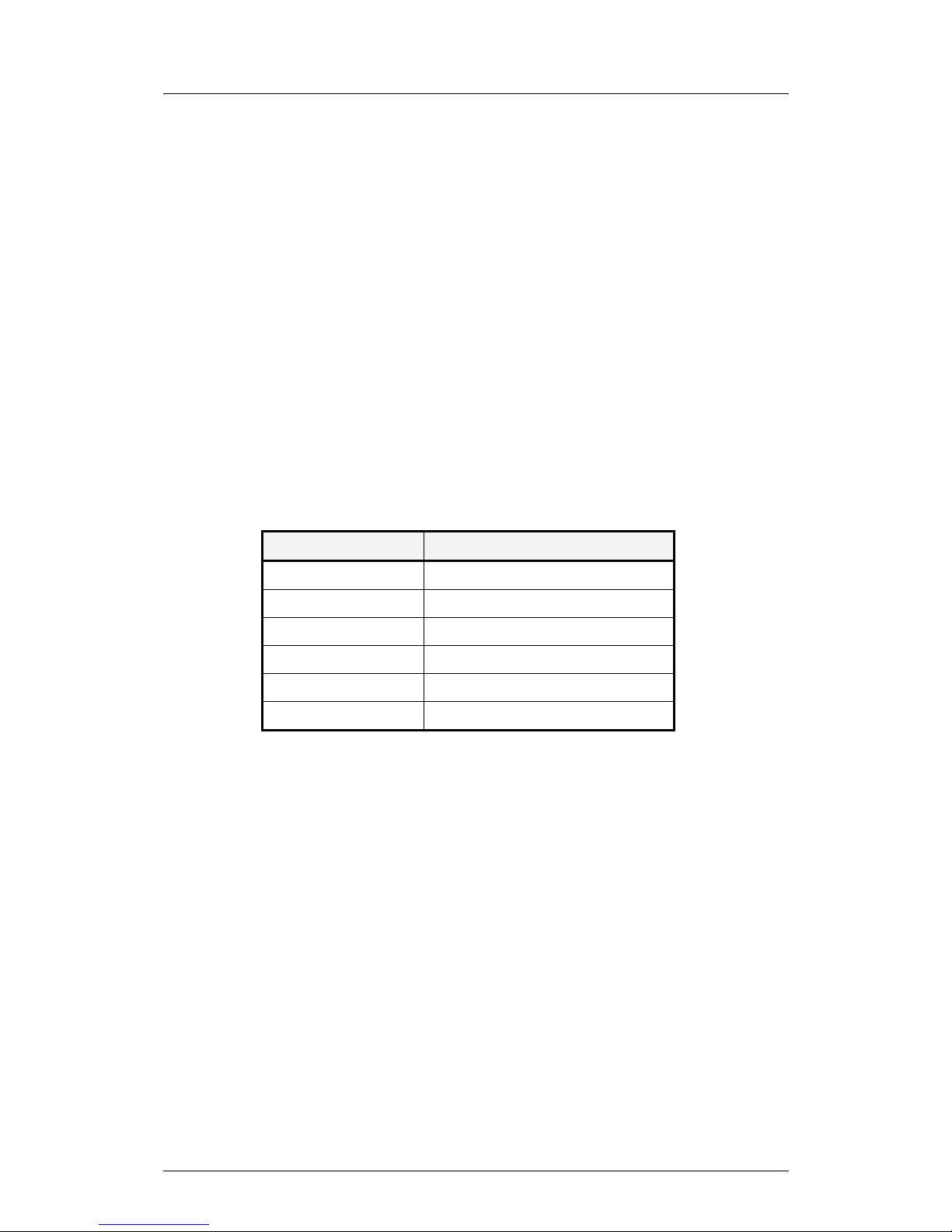
The SIM connection signals from the GR47 GSM module consist of:
SIGNAL DESCRIPTION
SIMVCC 3V or 5V Supply
GND System Ground
SIMCLK Synchronous Clock Output
SIMRST Reset Output
SIMDATA SIM Data Input/Output
SIMPRESENCE SIM Presence Detection Input
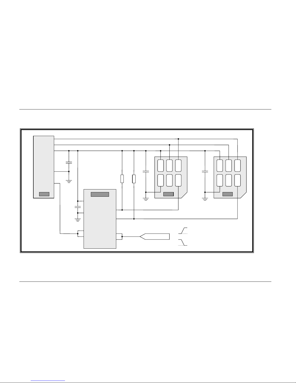
Each of the output signals and the supply connections can be connected
directly to both SIM holders. With a little signal conditioning these signals
have enough drive to fan out to two SIM holders without need for signal
buffering. For signal conditioning each SIM holder has a supply
decoupling capacitor associated with it.
The SIMDATA data input/output signal is the key to successful SIM
access. When active, the SIMDATA signal is pulled-up by the GR47. The
signal is bidirectional and is pulled-down by whichever side is sending
data. In the case of the disabled SIM holder in our dual SIM solution the
unused SIMDATA must be pulled-up to SIMVCC. This is a standard idle
condition for a SIM.
The method we have used to redirect the SIMDATA signal to whichever
SIM has been actively selected is by a dual SPST analogue switch.
The dual SPST analogue switch is part number NLAS325 from “ON
Semiconductor™”. This part has a wide operating voltage range and very
low quiescent supply current. In addition it has two independent switch
enable controls, ideally suited to this application as one is active high, the
Page 5

Dual SIM connection
LZT 123 7676 R1A 5
other active low, which permit a single control signal to select either SIM1
or SIM2 without additional logic circuitry.
The pull-up resistor value of 82kΩ on SIMDAT1 and SIMDAT2 not only
achieves the idle state pull-up but also compensates for the insertion of
the analogue switch into the SIMDATA signal.
Note : Due to the relatively high resistance of the pull-up on SIM Data
signals, the capacitance of the SIM Data line must be kept as low as
possible. Typically SIM circuits will not pass Type-Approval testing if the
SIM Data signal has a capacitive load greater than a few picoFarads.
Page 6

Dual SIM connection
LZT 123 7676 R1A 6
3 Operation
The operation of the dual SIM solution presented has been tested on
Type Approval Test equipment and has passed all electrical test
requirements with either SIM holder activated.
The selection of SIM1 or SIM2 was performed by mechanical switch
connecting IN1/IN2 to a pull-up resistor or SIMGND respectively.
The SIMPRESENCE detection input to the module can be used to trigger
a network-detach. A new network connection will be made when the
SIMPRESENCE signal is reactivated.
Note : It is not possible with this solution to receive calls on the SIM card
which is not activated.
Page 7
Dual SIM connection
LZT 123 7676 R1A 7
APPENDIX
Figure 1. Dual SIM schematic
VCC
RST
CLK
GND
VPP
DAT
SIMCLK
SIMRST
SIMVCC
GND
SIMDATA
VCC
RST
CLK
GND
VPP
DAT
VCC
GND
COM1
COM2
NO1
NC2
IN1
IN2
HIGH = SIM1
LOW = SIM2
SIMSELECT
82kΩ 82kΩ
100n
SIM1 SIM2
100n
100n
1
µ
F
+
GR47 NLAS325
 Loading...