

Page 1

Application Note
Embedded Applications
Controller Mode
Page 2

First edition (Novemebr 2004)
Sony Ericsson Mobile Communications. publishes this manual without
making any warranty as to the content contained herein. Further Sony
Ericsson Mobile Communications. reserves the right to make modifications,
additions and deletions to this manual due to typographical errors, inaccurate
information, or improvements to programs and/or equipment at any time and
without notice. Such changes will, nevertheless be incorporated into new
editions of this manual.
All rights reserved.
© Sony Ericsson Mobile Communications., 2004
Page 3

Embedded applications controller mode
Contents
Contents.....................................................................................................3
1 Introduction ........................................................................................4
2 Technical Description of Controller Mode.......................................... 5
2.1 Limitations – restricted functionality...........................................................5
3 Controller Mode Example ................................................................... 7
3.1 Solution Structure ......................................................................................7
3.2 Running the Example Script ......................................................................8
3.3 Controller Mode Script {Controller_Mode.sc} ............................................9
LZT 123 8015 R1A 3
Page 4

Embedded applications controller mode
1 Introduction
The radio device, when powered up normally, will start up
the GSM signalling software and look to register with a
GSM network. The Embedded Application script runs as a
background process, as and when the GSM software is
idle. Controller Mode is a mode of operation whereby the
radio device powers up with a minimal subset of
functionality. The GSM signalling software is halted, and
the Embedded Applications script will effectively have
“control” of the processor.
Controller Mode allows an application to run with more
predictable response times. If the GSM functionality is not
required for a long period of time, but some periodic
monitoring of IO’s is required, Controller Mode can be
used, giving faster response, lower latency and a more
predictable execution time during Controller Mode,
causing the current drawn to maintain a consistent low
level without network dependent fluctuations.
LZT 123 8015 R1A 4
Page 5

Embedded applications controller mode
2 Technical Description of Controller Mode
The radio device’s mode of operation can only be changed
on power up. Thus, to change the radio device between
Normal and Controller Modes, the radio device is reset.
The Embedded Application needs to call the Reset
function (rst()) specifying the mode to reset into – either
Normal or Control Mode. The radio device will then reset
into that mode.
When the radio device is reset into Controller Mode:
The radio device performs a software reset, jumping back
to the software start vector and beginning as from a
standard power up.
The radio device detects a pattern in flash to indicate that
Controller Mode is required on this power up. Software
then initializes only the hardware blocks that are required
for Controller Mode.
The OS initializes and all the processes are started. All
GSM software processes and interrupts are disabled,
apart from those servicing the watchdog and essential
timer features.
The radio device synchronizes the 13MHz clock to the
RTC clock before switching off the radio circuits and
regulators and starting the Embedded Application.
The script must be setup so that it is run from startup and
checks the status of the mode using a system status flag.
This will allow the script to switch between functionality
that works in Controller Mode, and functionality that is run
in Normal mode.
2.1 Limitations – restricted functionality
The operations in Controller Mode are limited to those
using the low level hardware interfaces and simple utility
functions. The functions that can be called in Controller
Mode are restricted, due to the fact that the GSM software
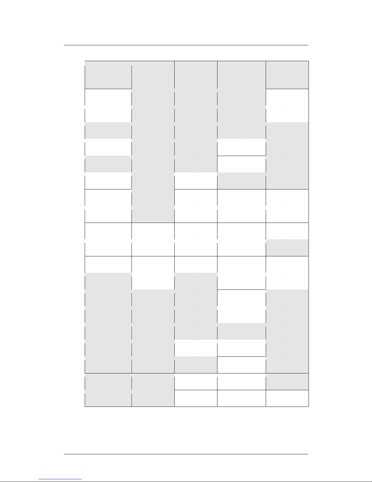
is non-operational. A list of the IFL functions and their
support in Controller Mode is given below. For IFL Name
Descriptions refer to Appendix A.
LZT 123 8015 R1A 5
Page 6
Embedded applications controller mode
IFL
Name
CM IFL
Name
CM IFL
Name
CM IFL Name CM IFL
Name
CM
Atcrt FALSE Dlyms TRUE Mset TRUE Scat TRUE Snqc FALSE
Atdst FALSE Dlys TRUE Mxc TRUE Scmp TRUE Snsp FALSE
Atoi TRUE Gtb TRUE Mxr TRUE Scpy TRUE Spc TRUE
Atsnd FALSE Gtf TRUE Mxs TRUE Sirfc FALSE Spic TRUE
Ccrc TRUE i2c TRUE Nvm TRUE Sirfd FALSE Spis TRUE
Chcrt FALSE i2r TRUE Pbi FALSE Slen TRUE Sstr TRUE
Chdst FALSE i2w TRUE Pbra FALSE Smsd FALSE Tcpc FALSE
Chr FALSE Io TRUE Pbrn FALSE Smsi FALSE Tcpr FALSE
Chsts FALSE Ipc FALSE Pbrtn FALSE Smsra FALSE Tcps FALSE
Chw FALSE Ipi FALSE Pdpa FALSE Smsrd FALSE Tm TRUE
Clip FALSE Ipo FALSE Pin FALSE Smsrm FALSE Udpr FALSE
Dbadd TRUE Iprh FALSE Prs TRUE Smsrs FALSE Udps FALSE
Dbadm TRUE Itoa TRUE Prtf TRUE Smss FALSE Utc TRUE
Dbdel TRUE Kyc TRUE Puct TRUE Smssc FALSE Utr TRUE
Dbfnd TRUE Kyd TRUE Puts TRUE Sncpy TRUE Utrl TRUE
Dbget TRUE Kyr TRUE Rc FALSE Sndev FALSE Uts TRUE
Dbghd TRUE Mcmp TRUE Rst TRUE Sndgpsp FALSE Utsl TRUE
Dbinx TRUE Mmve TRUE Sbfm FALSE Snllani FALSE Wd TRUE
Dbshd TRUE Mmve TRUE Sbs FALSE Snni FALSE
LZT 123 8015 R1A 6
Page 7

Embedded applications controller mode
3 Controller Mode Example
The following is an example of how to use controller
mode.
A system communicates its status by sending a short (16
byte) packet of data via a serial (RS232) link. This data
required to be sent to a host once a day in order to
maintain a central database with details of the system
status.
The status packets begin with a byte ‘S’ and end with the
byte ‘E’.
3.1 Solution Structure
The radio device could be integrated into the system,
connecting UART 3 to the system’s serial link. The
Embedded Application would then read the status packets
in, and batch send them off to the host in an SMS
message.
The application is mainly run in Controller Mode, as no
GSM activity is required until the SMS is sent. Once a set
number of packets has been reviewed, or a day has
passed (whichever the sooner), the radio device will then
switch back to Normal Mode and send the SMS with the
status report. The radio device then resets to Controller
Mode and listens for more status packets.
(If there is a requirement for a stringent timing on receiving
the status reports, Controller Mode will be necessary in
order to give reliable response time.)
The Application Listing is given at the end of this note. The
Application makes use of a database functionality to store
the status reports while in Controller Mode, so that they
can be read and placed into a SMS message for sending
in Normal Mode. Refer to the IDE online help for detailed
descriptions of each of the IFL functions used in this script.
The application script consists of 3 functions:
• Main() - called on start-up and determines which mode
function is called.
• DoControl () - Initializes the database, UART and
buffers. Waits for a packet of data, and once it has
been received checks the start and stop bytes to make
LZT 123 8015 R1A 7
Page 8

Embedded applications controller mode
sure it is valid report. If so, the report is stored in the
database, and a count is incremented. Once the count
reaches 10, or a day has passed since an update was
last sent, the radio device resets into Normal Mode to
send the status update.
• DoGSM() - Restore the database, and reads out each
new record, storing them in the SMS string, before
deleting the record. Once all the records have been
transferred, the SMS is sent. The radio device then
resets into Controller Mode and awaits further data.
3.2 Running the Example Script
In order to run this example script:
1
2
3
4
Connect the UART3 Tx and Rx lines via an RS232
level shifter to a COM Port on your PC, the Demo
Board which comes with the developers kit can be
used for this.
Load the script into the Editor, and replace the
SMS_NUMBER field with a valid mobile number the
SMS reports should be sent to.
Download the script, making sure to check the “Run
Script on Startup” box. This will enable the application
to run on every startup – crucial for the functionality
with Controller Mode.
Run the script. (You can see the debug outputs if you
monitor the UART2 port (115200 baud, 8 data bits, no
parity) and set the service pin HIGH prior to power on)
The radio device will have reset into Controller Mode and
be waiting for data. To enter data, use a terminal package
and send packets of the form “SxxxxxxxxxxxxxE” where x
is any 7-bit ASCII value. Once 10 valid packets have been
received, or a day has passed, the radio device will reset
and send the data in an SMS to the number you have
entered.
LZT 123 8015 R1A 8
Page 9

Embedded applications controller mode
3.3 Controller Mode Script {Controller_Mode.sc}
int CONTROLLER_MODE = 11;
int REG_STATUS = 10;
int REGISTERED = 1;
char START_BYTE = 'S';
char STOP_BYTE = 'E';
int CONTROLTIME = 18748800; /* 1 day - time in ticks 217 a second *60*60*24 */
int DATA_PKT_SIZE = 15;
int RECORD_THRESHOLD = 10;
char SMS_NUMBER[13] = “012345678901”; /*replace this with a valid Mobile Phone
number*/
int SMSBUFSIZE = (DATA_PKT_SIZE*RECORD_THRESHOLD)+1;
char NEW_FLAG = 0x01;
char Buf[DATA_PKT_SIZE+1];
int db_id = 1;
/*Carry out Controller Mode tasks */
DoControl()
{
int Count = 0;
int recid = 0;
int StartTime = tm();
int TimeExceeded;
mset(Buf,0,DATA_PKT_SIZE+1);
/*restore and open db*/
dbadm(1);
/*destroy all db instances*/
dbadm(2);
/*Create db - db_id should always be 1*/
db_id = dbadm(0);
prtf(“\n New db_id = %d”,db_id);
/*open UART3, 9600 */
utc(1,3);
/*loop looking for incoming packets*/
while(1)
{
/*if at least a packet of data is available*/
if(utrl() >= DATA_PKT_SIZE)
{
/*read packet*/
utr(Buf,DATA_PKT_SIZE);
prtf(“\n Read packet %s”,Buf);
/* verify packet*/
if((Buf[0] == START_BYTE) && (Buf[DATA_PKT_SIZE -1] ==
STOP_BYTE))
{
/*Add to db - flag as new */
if(dbadd(db_id,Buf,DATA_PKT_SIZE,NEW_FLAG,0,0) == 0)
{
prtf(“\n Error Adding to DB!”);
}
Count++;
prtf(“\n Count = %d”,Count);
}
}
TimeExceeded = (tm() - StartTime) > CONTROLTIME;
if(TimeExceeded || Count >= RECORD_THRESHOLD)
{
rst(0); /*Start up GSM mode*/
}
prtf(“\n Waiting for Data!”);
dlys(1); /*poll once a second */
}
}
/*Carry Out GSM Tasks*/
DoGSM()
LZT 123 8015 R1A 9
Page 10

Embedded applications controller mode
LZT 123 8015 R1A 10
{
char SMS_Buf[SMSBUFSIZE];
int CurrRec = 0;
int CurrLen = 0;
int Len;
prs(0);
/*restore and open db*/
if(dbadm(1) != db_id)
{
/*db error - return to Controller Mode!*/
rst(1);
}
mset(SMS_Buf,0,SMSBUFSIZE);
while(gtb(REG_STATUS) != REGISTERED);
prtf(“\n Registered!”);
/*Send SMS's with IO Data Retrieved*/
CurrRec = dbfnd(db_id,1,0,NEW_FLAG,0,0);
while(CurrRec != 0)
{
Len = dbget(db_id,CurrRec,SMS_Buf + CurrLen);
CurrLen = CurrLen + Len;
if(CurrLen >= SMSBUFSIZE)
{
prtf(“\n Too Much Data!”);
break;
}
dbdel(db_id,CurrRec);
CurrRec = dbfnd(db_id,1,0,NEW_FLAG,0,0);
}
if(slen(SMS_Buf) > 0)
{
int err;
atcrt();
prtf(“\n SMS String = %s”,SMS_Buf);
err = smss(SMS_NUMBER,SMS_Buf,129,slen(SMS_NUMBER),SMSBUFSIZE);
if(err != 0)
{
prtf(“\n Failed sending SMS!”);
}
atdst();
}
rst(1); /* reset in Controller Mode */
}
/*Main Function*/
main()
{
if(gtf(CONTROLLER_MODE))
{
DoControl();
}
else
{
DoGSM();
}
}
 Loading...