

Sony ZSM-35 Service manual
ZS-M35
SERVICE MANUAL
Ver 1.2 2001.07
U.S. and foreign patents licensed from Dolby Laboratories
Licensing Corporation.
AUDIO POWER SPECIFICATIONS (US model)
POWER OUTPUT AND TOTAL
HARMONIC DISTORTION
With 4-ohm loads, both channels driven from
150 - 10,000 Hz; rated 4 W per channelminimum RMS power, with no more than 10%
total harmonic distortion in AC operation.
CD
Section
MD
Section
US Model
Canadian Model
Taiwan Model
Model Name Using Similar Mechanism PMC-20
CD Mechanism Type KSM-213CDM
Optical Pick-up Name KSS-213C
Model Name Using Similar Mechanism PMC-MD55
MD Mechanism Type MDM-5GA
Base Unit Name MBU-5A
Optical Pick-up Name KMS-260B
CD player section
System
Compact disc digital audio system
Laser diode properties
Material: GaAlAs
Wave length: 785 nm
Emission duration: Continuous
Laser output: Less than 44.6 µW
(This output is the value measured at a distance of
about 200 mm from the objective lens surface on
the optical pick-up block with 7 mm aperture.)
Spindle speed
200 r/min (rpm) to 500 r/min (rpm) (CLV)
Number of programme positions
2
Frequency response
20 - 20,000 Hz +1/–2 dB
Wow and flutter
Below measurable limit
Radio section
Frequency range
FM: 87.5 - 108 MHz
AM: 530 - 1,710 kHz
Antennas
FM: Telescopic antenna
AM: AM loop antenna
SPECIFICATIONS
MD player section
System
Minidisc digital audio system
Disc
MiniDisc
Laser diode properties
Material: GaAlAs
Wave length: 785 nm
Emission duration: Continuous
Laser output: Less than 44.6 µW
(This output is the value measured at a distance of
about 200 mm from the objective lens surface on
the optical pick-up block with 7 mm aperture.)
Recording/playback time
Stereo recording:
Maximum 80 minutes (with MDW-80)
Monaural recording:
Maximum 160 minutes (with MDW-80)
Revolutions
400 rpm to 900 rpm (CLV)
Error correction
Advanced Cross Interleave Reed Solomon Code
(ACIRC)
Sampling frequency
44.1 kHz
– Continued on next page –
PERSONAL MINIDISC SYSTEM
9-927-183-33
2001G0400-1
© 2001.7
Sony Corporation
Personal Audio Company
Shinagawa Tec Service Manual Production Group
– 1 –
Coding
Adaptive TRansform Acoustic Coding (ATRAC)
Modulation system
EFM (Eight-to-Fourteen Modulation)
Number of programme positions
2 stereo programme positions
Frequency response
20 - 20,000 Hz +1/–2 dB
Signal-to-noise ratio
Over 80 dB (during playback)
Wow and flutter
Below measurable limit
General
Speaker
Full-range: 8 cm (3 in.) dia., 4 ohms, cone type (2)
Inputs
LINE IN (stereo minijack): Sensitivity 436 mV/
870 mV
Outputs
Headphones jack (stereo minijack) (1):
For 32 ohms impedance headphones
Power output (excluding US model)
5 W + 5 W (at 4 ohms, 10 % harmonic distortion
in AC operation)
Power requirements
For personal minidisc system:
120 V AC, 60 Hz
For back-up memory:
4.5 V DC, 3 size AA (R6) batteries
For remote control:
3 V DC, 2 size AA (R6) batteries
Power consumption
24 W
Dimensions (incl. projecting parts)
Approx. 498.5 × 173.5 × 227 mm (w/h/d)
3
(17
/4 × 6 1/2 × 9 1/2 inches)
Mass
Approx. 5.2 kg (13 lb. 4 oz)
Supplied accessories
AC power cord (1)
Remote control (RMT-CM35A) (1)
AM loop antenna (1)
Design and specifications are subject to change
without notice.
SAFETY CHECK-OUT
After correcting the original service problem, perform the following
safety check before releasing the set to the customer:
Check the antenna terminals, metal trim, “metallized” knobs,
screws, and all other exposed metal parts for AC leakage. Check
leakage as described below.
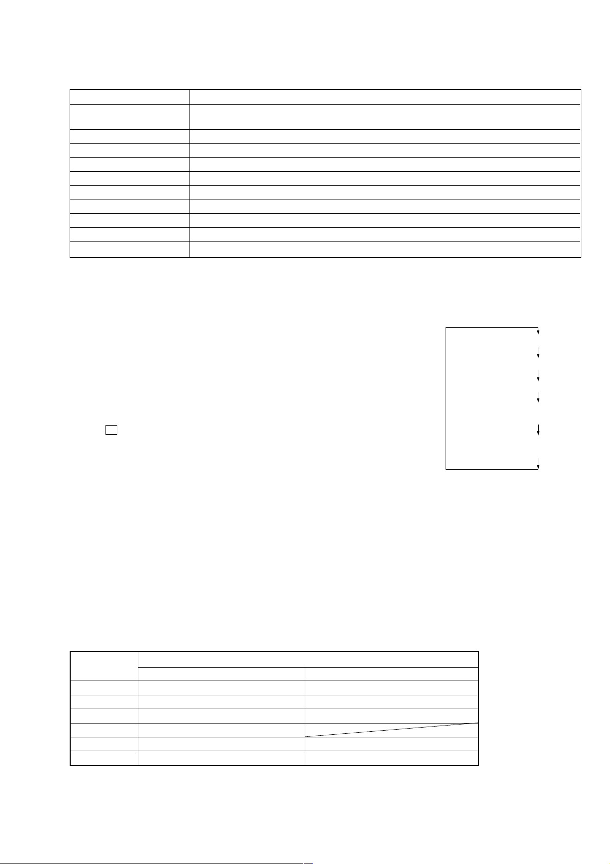
LEAKAGE TEST
The AC leakage from any exposed metal part to earth ground and
from all exposed metal parts to any exposed metal part having a
return to chassis, must not exceed 0.5 mA (500 microamperes).
Leakage current can be measured by any one of three methods.
1. A commercial leakage tester, such as the Simpson 229 or RCA
WT-540A. Follow the manufacturers’ instructions to use these
instruments.
2. A battery-operated AC milliammeter. The Data Precision 245
digital multimeter is suitable for this job.
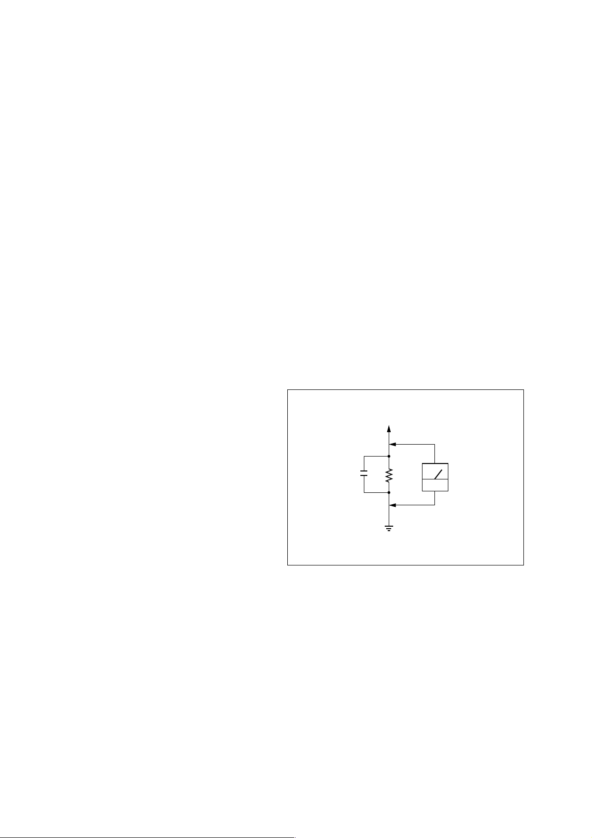
3. Measuring the voltage drop across a resistor by means of a VOM
or battery-operated AC voltmeter. The “limit” indication is 0.75
V, so analog meters must have an accurate low-voltage scale.
The Simpson 250 and Sanwa SH-63Trd are examples of a passive
VOM that is suitable. Nearly all battery operated digital
multimeters that have a 2V AC range are suitable. (See Fig. A)
To Exposed Metal
Parts on Set
0.15µF
1.5k
Ω
Earth Ground
AC
voltmeter
(0.75V)
Fig. A. Using an AC voltmeter to check AC leakage.
SAFETY-RELATED COMPONENT WARNING!!
COMPONENTS IDENTIFIED BY MARK 0 OR DOTTED LINE
WITH MARK 0 ON THE SCHEMATIC DIAGRAMS AND IN
THE PARTS LIST ARE CRITICAL TO SAFE OPERATION.
REPLACE THESE COMPONENTS WITH SONY PARTS WHOSE
PART NUMBERS APPEAR AS SHOWN IN THIS MANUAL
OR IN SUPPLEMENTS PUBLISHED BY SONY.
ATTENTION AU COMPOSANT AYANT RAPPORT
LES COMPOSANTS IDENTIFIÉS PAR UNE MARQUE 0 SUR
LES DIAGRAMMES SCHÉMATIQUES ET LA LISTE DES
PIÈCES SONT CRITIQUES POUR LA SÉCURITÉ DE
FONCTIONNEMENT. NE REMPLACER CES COMPOSANTS
QUE PAR DES PIÈCES SONY DONT LES NUMÉROS SONT
DONNÉS DANS CE MANUEL OU DANS LES SUPPLÉMENTS
PUBLIÉS PAR SONY.
À LA SÉCURITÉ!!
– 2 –

TABLE OF CONTENTS
1. SERVICING NOTES
1-1. Notes on Handling the Optical Pick-up Block or Base Unit .. 4
1-2. Notes on Laser Diode Emission Check............................... 4
1-3. Notes on Chip Component Replacement ............................ 4
1-4. Flexible Circuit Board Repairing ........................................ 4
1-5. Chuck Plate Jig on Repairing ..............................................4
1-6. Demonstration ..................................................................... 4
1-7. Checking the Laser Diode and Focus Search Operation.....4
1-8. Jig for Checking BD Board Waveform ............................... 5
1-9. Checks Prior to Parts Replacement and Adjustments ......... 6
1-10. Change of Pulley ................................................................. 6
2. GENERAL
Playing a CD .......................................................................7
Recording a whole CD ........................................................ 7
Playing an MD..................................................................... 8
Listening to the radio...........................................................8
3. DISASSEMBLY
3-1. Cabinet (Rear) Assy ............................................................ 9
3-2. Power Board........................................................................9
3-3. Cabinet (Upper) Assy........................................................ 10
3-4. MD Block Assy.................................................................10
3-5. Tuner Board....................................................................... 11
3-6. Jack Board .........................................................................11
3-7. LED Board ........................................................................ 12
3-8. Key Board ......................................................................... 12
3-9. Top Board .......................................................................... 13
3-10. FL Board ........................................................................... 13
3-11. Main board ........................................................................ 14
3-12. CD Board .......................................................................... 14
3-13. CD Mechanism Block ....................................................... 15
3-14. DG Board .......................................................................... 15
3-15. Plate (Front), Shield .......................................................... 16
3-16. MD Mechanism Block-1 (MDM-5GA) ............................ 16
3-17. MD Mechanism Block-2 (Slider (Cam) Assy) ................. 17
3-18. MD Mechanism Block-3 (BD Board)...............................18
3-19. MD Mechanism Black-4 (SW Board)............................... 18
6. DIAGRAMS
6-1. IC Pin Function Descriptions ............................................ 33
6-2. Circuit Boards Location .................................................... 42
6-3. Block Diagram –Tuner Section–....................................... 43
6-4. Block Diagram –MD Section–..........................................46
6-5. Block Diagram –CD Section–........................................... 49
6-6. Block Diagram –Audio Section– ...................................... 51
6-7. Schematic Diagram –CD Section (1/2)–...........................53
6-8. Schematic Diagram –CD Section (2/2)–...........................55
6-9. Printed Wiring Boards –CD Section– ............................... 57
6-10. Printed Wiring Boards –Tuner Section– ........................... 59
6-11. Schematic Diagrams –Tuner Section– .............................. 61
6-12. Printed Wiring Boards –BD Section– ............................... 63
6-13. Schematic Diagram –BD Section (1/2)–...........................65
6-14. Schematic Diagrams –BD Section (2/2)– ......................... 67
6-15. Schematic Diagram –DG Section– ................................... 69
6-16. Schematic Diagram –DG Section– ................................... 71
6-17. Printed Wiring Board –DG Section– .................................73
6-18. Printed Wiring Board –Main Section– .............................. 75
6-19. Schematic Diagram –Main Section (1/3)– ........................77
6-20. Schematic Diagram –Main Section (2/3)– ........................79
6-21. Schematic Diagram –Main Section (3/3)– ........................81
6-22. Printed Wiring Boards –Panel Section– ............................83
6-23. Schematic Diagrams –Panel Section–............................... 85
6-24. Printed Wiring Boards –Switch Section– .......................... 87
6-25. Schematic Diagrams –Switch Section– ............................ 89
6-26. Printed Wiring Boards –Power Supply Section– .............. 91
6-27. Schematic Diagrams –Power Supply Section– ................. 93
6-28. IC Block Diagrams............................................................ 95
7. EXPLODED VIEWS
7-1. Cabinet (Rear) Section .................................................... 101
7-2. Cabinet (Front) Section ................................................... 102
7-3. Cabinet (Upper) Section.................................................. 103
7-4. MD Block Section...........................................................104
7-5. MD Mechanism Section (MDM-5GA) ..........................105
7-6. MD Base unit Section (MBU-5A) ................................. 106
7-7. Optical Pick-up Section (KSM-213CDM)......................107
4. TEST MODE
4-1. MD section ........................................................................ 19
5. ELECTRICAL ADJUSTMENTS
5-1. Tuner section .....................................................................22
5-2. MD section ........................................................................ 24
5-3. CD section .........................................................................31
8. ELECTRICAL PARTS LIST....................................108
– 3 –
SECTION 1
SERVICING NOTES
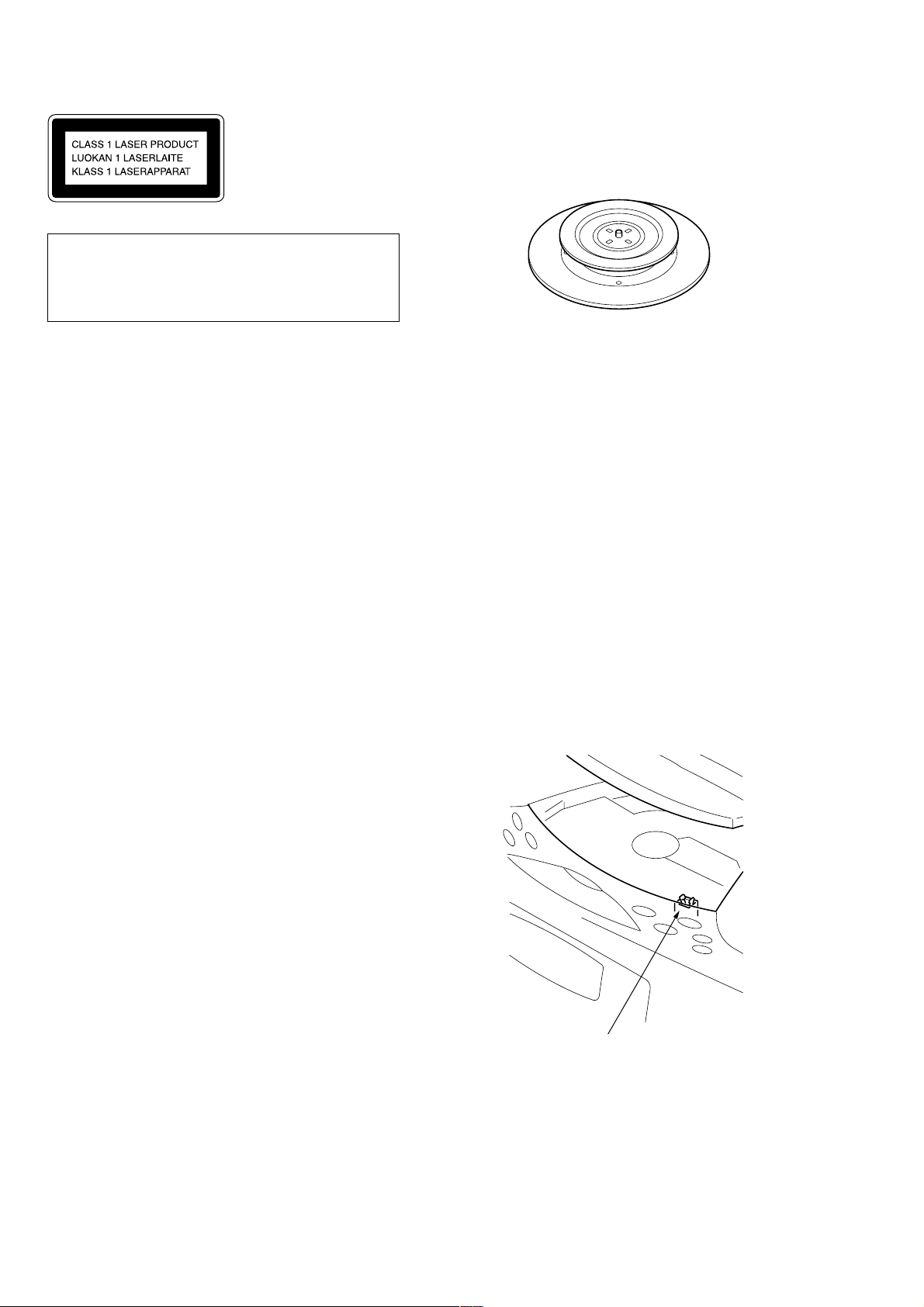
This Compact Disc player
is classified as a CLASS 1
LASER product.
The CLASS 1 LASER
PRODUCT label is located
on the bottom exterior.
CAUTION
Use of controls or adjustments or performance of procedures other than those specified herein may result in hazardous radiation exposure.
1-1. NOTES ON HANDLING THE OPTICAL PICK-UP
BLOCK OR BASE UNIT
The laser diode in the optical pick-up block may suffer electrostatic break-down because of the potential difference generated
by the charged electrostatic load, etc. on clothing and the human
body.
During repair, pay attention to electrostatic break-down and also
use the procedure in the printed matter which is included in the
repair parts.
The flexible board is easily damaged and should be handled with
care.
1-2. NOTES ON LASER DIODE EMISSION CHECK
The laser beam on this model is concentrated so as to be focused
on the disc reflective surface by the objective lens in the optical
pick-up block. Therefore, when checking the laser diode emission, observe from more than 30 cm away from the objectiv e lens.
1-3. NO TES ON CHIP COMPONENT REPLACEMENT
• Never reuse a disconnected chip component.
• Notice that the minus side of a tantalum capacitor may be dam-
aged by heat.
1-5. CHUCK PLATE JIG ON REPAIRING
On repairing CD section, playing a disc without the CD lid, use
Chuck Plate Jig.
• Code number of Chuck Plate Jig: X-4918-255-1
1-6. DEMONSTRATION
This set enters the demonstration mode about 10 seconds after the
power cord is connected. The demonstration displays such as
“DEMONSTRA TION MODE” and “CREA TE YOUR ORIGINAL
MD” then appears.
When no operation is entered for one minute after the [POWER]
button is turned on, the demonstration mode is also entered.
T o release the demonstration mode, set the timer in this set or press
and hold down the [NO/CANCEL] button for about 2 seconds.
1-7. CHECKING THE LASER DIODE AND FOCUS
SEARCH OPERATION
1. Turn on the POWER and open the CD cover.
2. As shown below, push S402 (CD DOOR) with a screwdriver or
other tool.
3. Press the CD button.
4. Check the objective lens to make sure that the laser diode is
emitting light. If not so, the auto power control circuit or optical
pickup would be damaged.
Verify that the objective lens moves vertically three times for
focus search.
1-4. FLEXIBLE CIRCUIT BOARD REPAIRING
• Keep the temperature of the soldering iron around 270 ˚C during repairing.
• Do not touch the soldering iron on the same conductor of the
circuit board (within 3 times).
• Be careful not to apply force on the conductor when soldering
or unsoldering.
S402
– 4 –
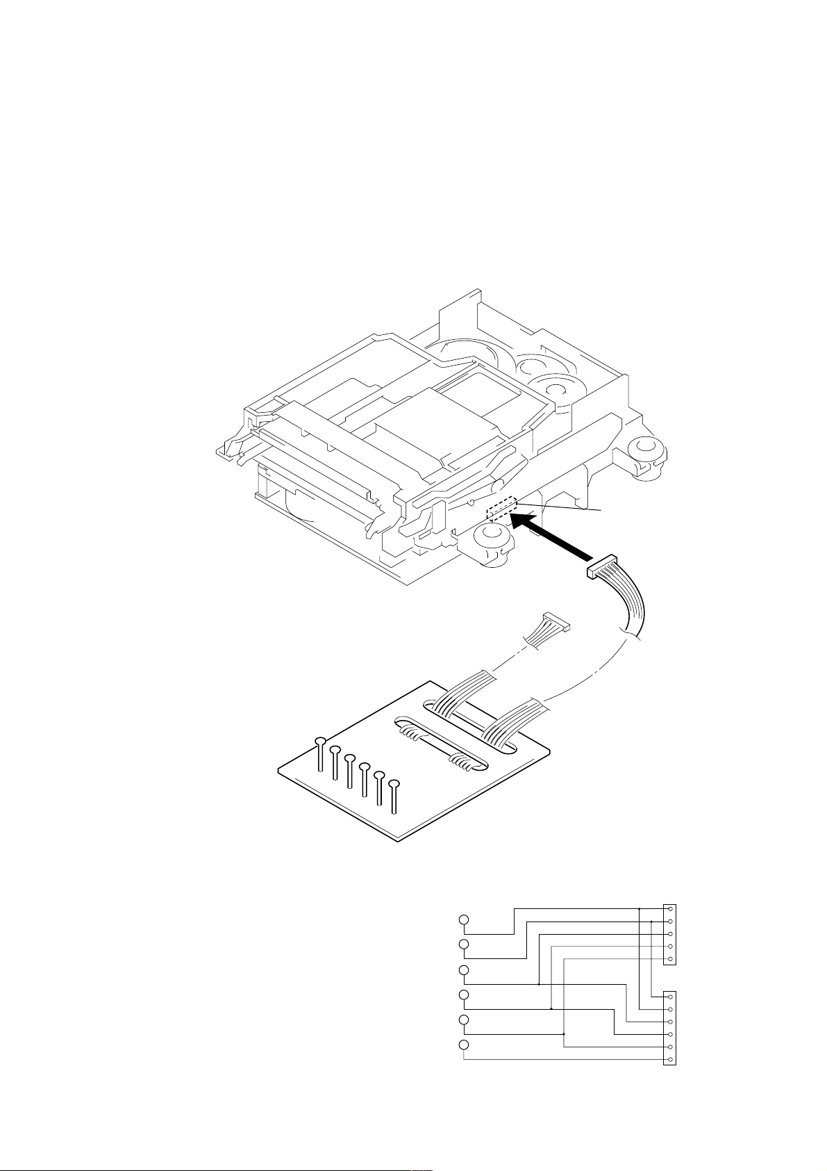
1-8. JIG FOR CHECKING BD BOARD WAVEFORM
r
3
5
The special jig (J-2501-149-A) is useful for checking the waveform of the BD board. The names of terminals and the checking items to
be performed are shown as follows.
GND: Ground
I+3V : For measuring IOP (Check the deterioration of the optical pick-up laser)
IOP : For measuring IOP (Check the deterioration of the optical pick-up laser)
TEO : TRK error signal (Traverse adjustment)
VC : Reference level for checking the signal
RF : RF signal (Check jitter)
Mechanism deck
RF
VC
TEO
IOP
I+3V
GND
RF
VC
TEO
CN110
6P connecto
5P connector
1
RF
VC
TEO for MDMIOP
I+3V
5
1
IOP
I+3V
GND
– 5 –
VC
RF
TEO
for MDM-
IOP
I+3V
6
GND

1-9. CHECKS PRIOR TO PARTS REPLACEMENT AND ADJUSTMENTS (FOR MD SECTION)
m
Before performing repairs, perform the following checks to determine the faulty locations up to a certain extent.
Details of the procedures are described in “5 Electrical Adjustments”.
Laser power check
(6-1 : See page 26)
Focus bias check
(6-2 : See page 26)
C PLAY check
(6-3 : See page 26)
Self-recording/playback
check
(6-4 : See page 26)
Criteria for Determination
(Unsatisfactory if specified value is not satisfied)
• 0.9 mW power
Specified value : 0.84 to 0.92 mW
• 7.0 mW power
Specified value : 6.8 to 7.2 mW
lop (at 7mW)
• Labeled on the optical pickup
Iop value ± 10mA
• Error rate check
Specified value : For points a, b, and c
C1 error : About 200
ADER : Below 2
• Error rate check
Specified value:
a. When using test disc (MDW-74/AU-1)
C1 error : Below 80
ADER : Below 2
b. When using check disc (TDYS-1)
C1 error : Below 50
• CPLAY error rate check
Specified value:
C1 error : Below 80
ADER : Below 2
• Clean the optical pick-up
• Adjust again
• Replace the optical pick-up
• Replace the optical pick-up
• Replace the optical pick-up
• Replace the optical pick-up
If always unsatisfactory:
• Replace the overwrite head
• Check for disconnection of the circuits around the
overwrite head
If occasionally unsatisfactory:
• Check if the overwrite head is distorted
• Check the mechanism around the sled
Measure if unsatisfactory:
Note:
The criteria for determination above is intended merely to determine if satisfactory or not, and does not serve as the specified value for
adjustments.
When performing adjustments, use the specified values for adjustments.
1-10. CHANGE OF PULLEY
pulley
M102, 103
Install the pulley to the motor.
2.5 m
– 6 –
Basic Operations
SECTION 2
GENERAL
This section is extracted
from instruction manual.
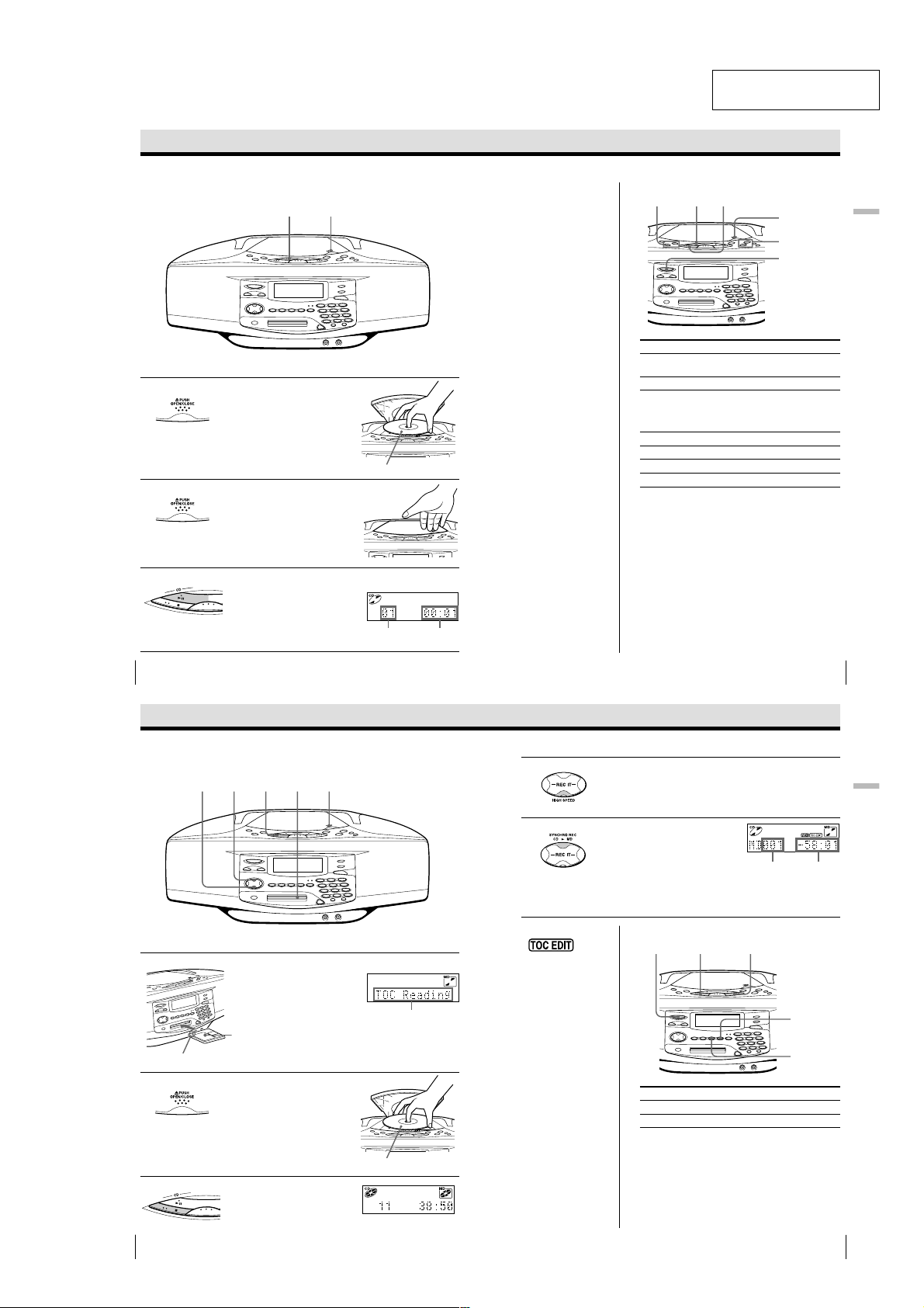
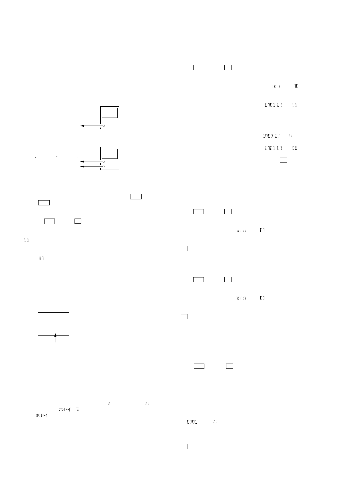
Playing a CD
For hookup instructions, see pages 57 - 59.
1 Press Z PUSH OPEN/CLOSE
2 Close the lid of the CD
3 Press CD u (CD N on the
Basic Operations
4
down to open the CD
compartment and place the CD
on the CD compartment.
compartment.
remote).
The player turns on (direct
power-on) and the player plays
all the tracks once.
1, 23
With the label side up
Display
Track
number
Playing
time
Tip
Next time you want to
listen to a CD, just press
CD u. The player
turns on automatically
and starts playing the
CD.
Use these buttons for additional operations
To Press
adjust the volume VOLUME +, –
stop playback CD x
pause playback CD u (CD X on the
go to the next track >
go back to the previous track .
remove the CD Z PUSH OPEN/CLOSE
turn on/off the player POWER
CD u. , >
CD x
Z PUSH
OPEN/CLOSE
VOLUME –, +
POWER
(VOL +, – on the remote)
remote)
Press the button again to
resume play after pause.
Basic Operations
Basic Operations
5
Recording a whole CD
(Synchronized recording)
34
5
For hookup instructions, see pages 57 - 59.
1 Insert a recordable MD (direct
Insert in the direction of
the arrow
2 Press Z PUSH OPEN/CLOSE
power-on).
With the label
side up
and place the CD on the CD
compartment.
Press Z PUSH OPEN/CLOSE
again to close the CD
compartment.
3 Press CD x.
Basic Operations
6
21
Display
After “TOC Reading” is
displayed, the disc name
will be displayed if it is
labeled.
With the label side up
4 To record at high speed, press
5 Press SYNCHRO REC CD N
Notes
• After you
stop recording, do not
disconnect the AC
power cord or move
the player while “TOC
EDIT” is flashing in the
display. If you do so,
recording may not be
done properly.
• When you record a
whole CD, you cannot
pause recording.
Tips
• Adjusting the volume or
the audio emphasis
(page 49) will not affect
the recording level.
Keep the volume at a
moderate level so as to
prevent the sound from
skipping.
• To record over the
previous recording, see
page 33.
• Once the clock is set, the
recording date and time
are stamped
automatically (page 50).
• You can label an MD or a
track during recording
(page 44).
HIGH SPEED.
The indicator lights up.
To record at normal speed, skip this step.
MD.
The player starts recording
automatically.
If the MD has any previous
recording, recording will be
made from the last recorded
position.
Use these buttons for additional operations
POWER
To Press
stop recording MD x or CD x
turn on/off the player POWER
If “CD>MD OK?” alternates with time display
There is not enough space on the MD to record the whole
CD.
If it is all right to record as much as possible and cancel
recording of some tracks, press YES•ENTER. To stop
recording, press NO•CANCEL.
If any other messages are displayed, see page 72.
CD x
Track number
of MD
MD x
Remaining
recording
time of MD
YES
ENTER
NO
CANCEL
Basic Operations
Basic Operations
7
– 7 –
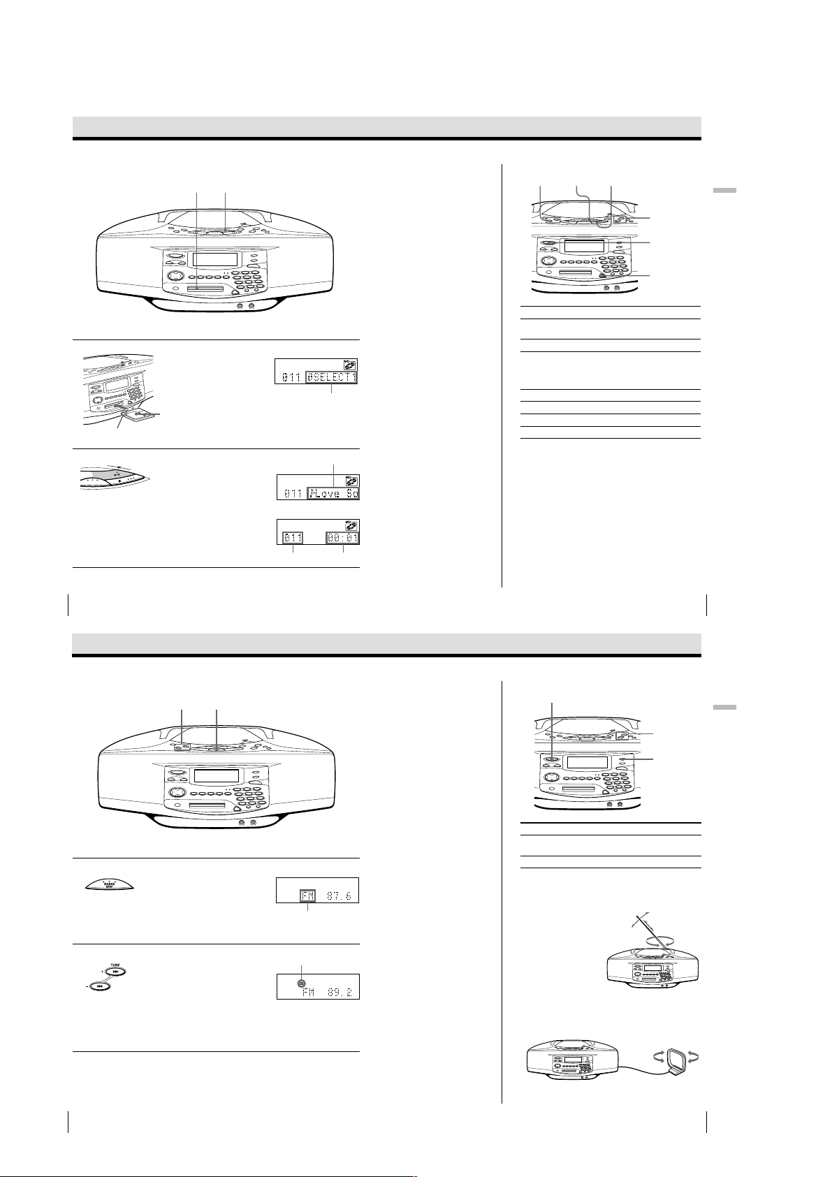
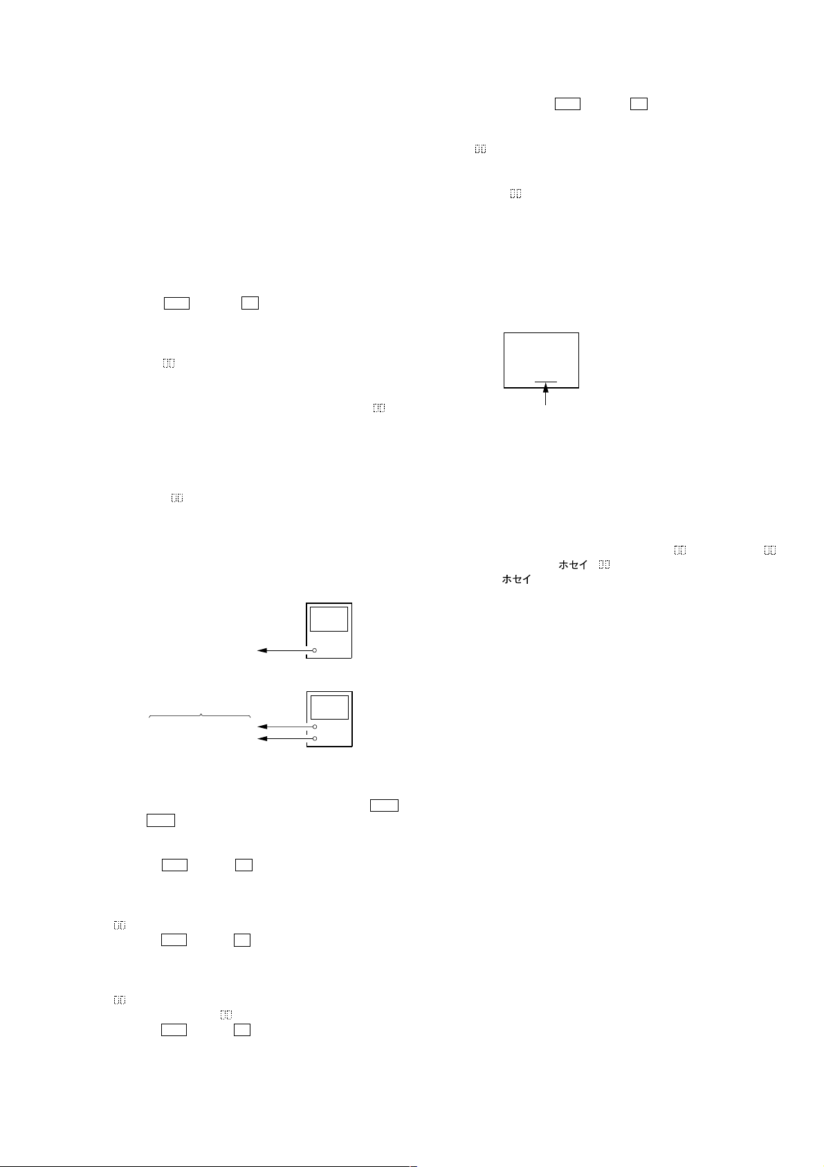
Playing an MD
Use these buttons for additional operations
2
1
., >
MD u
MD x
Basic Operations
VOLUME –, +
POWER
Z
For hookup instructions, see pages 57 - 59.
1 Insert the MD (direct power-on).
With the label
Insert in the direction of
the arrow
2 Press MD u (MD N on the
Basic Operations
8
side up
remote).
The player plays all the tracks
once.
Listening to the radio
2
1
Display
After “TOC Reading” is
displayed, the disc name
will be displayed if it is
labeled.
Track name is displayed
if it is labeled.
m
Track number
Playing time
Tip
Next time you want to
listen to a MD, just press
MD u. The player
turns on automatically
and starts playing the
MD.
To Press
adjust the volume VOLUME +, –
stop playback MD x
pause playback MD u (MD X on the
go to the next track >
go back to the previous track .
remove the MD Z
turn on/off the player POWER
Use these buttons for additional operations
POWER
(VOL +, – on the remote)
remote)
Press the button again to
resume play after pause.
Basic Operations
VOLUME –, +
9
Basic Operations
For hookup instructions, see pages 57- 59.
1 Press RADIO BAND until the
2 Hold down TUNE + or TUNE –
Basic Operations
10
band you want appears in the
display (direct power-on).
until the frequency digits begin to
change in the display.
The player automatically scans
the radio frequencies and stops
when it finds a clear station.
If you can’t tune in a station,
press TUNE + or TUNE –
repeatedly to change the
frequency step by step.
Display
“FM” or “AM” appears
Indicates an FM stereo
broadcast
– 8 –
Tips
• If the FM broadcast is
noisy, press MONO/
ST•REPEAT (MODE on
the remote) until
“Mono” appears in the
display and radio will
play in monaural.
• Next time you want to
listen to the radio, just
press RADIO BAND.
The player turns on
automatically and starts
playing the previous
station.
MONO/ST
REPEAT
To Press
adjust the volume VOLUME +, –
turn on/off the radio POWER
To improve broadcast reception
FM:
Reorient the antenna for FM.
AM:
Keep the AM loop antenna as far as possible from the
player and reorient it.
(VOL +, – on the remote)
Basic Operations
11
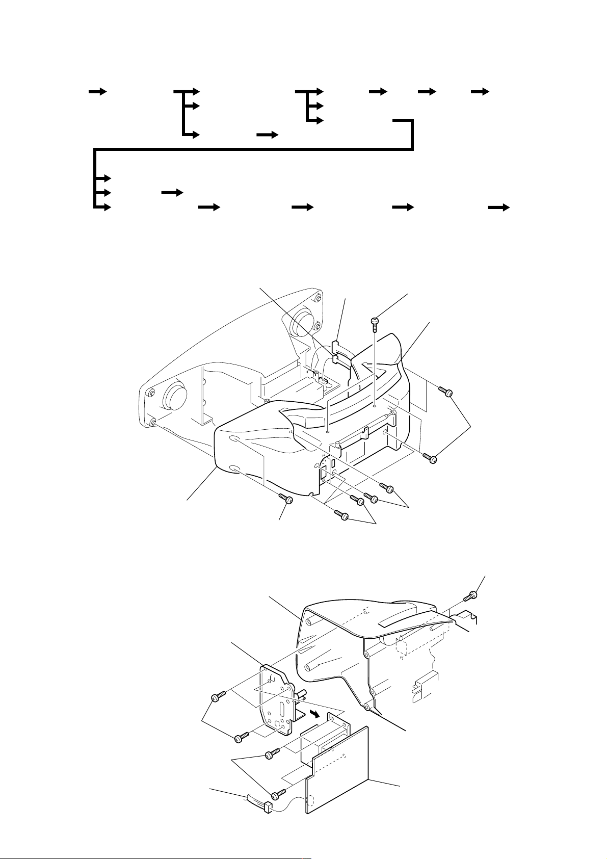
SECTION 3
4
DISASSEMBLY
Note : This set can be disassemble according to the following sequence.
Set Cabinet (Rear)
Assy
DG Board
LED Board
Plate (Front), Shield
Note : Follow the disassembly procedure in the numerical order given.
3-1. CABINET (REAR) ASSY
Cabinet (Upper) Assy
Power Board
Tuner Board
Key Board
MD Mechanism
Block - 1
(MDM-5GA)
Jack Board
MD Mechanism
Block - 2
(Slider (Cam) Assy)
7 CN401
FL Board Main
Top Board
Board
MD Block Assy
6 CN402
CD
Board
MD Mechanism
Block - 3
(BD Board)
1 BVTP 3x12
handle
CD Mechanism
Block
MD Mechanism
Block - 4
(SW board)
3-2. POWER BOARD
3 BVTP 4x12
8 cabinet (rear) assy
cabinet (rear) assy
chassis, transformer
5 BVTP 3x14
5
2 BVTP 3x1
3 BVTP 3x14
4 BVTP 3x12
1 BVTP 3x12
4 BVTP 3x12
2 CN903
6 POWER board
– 9 –
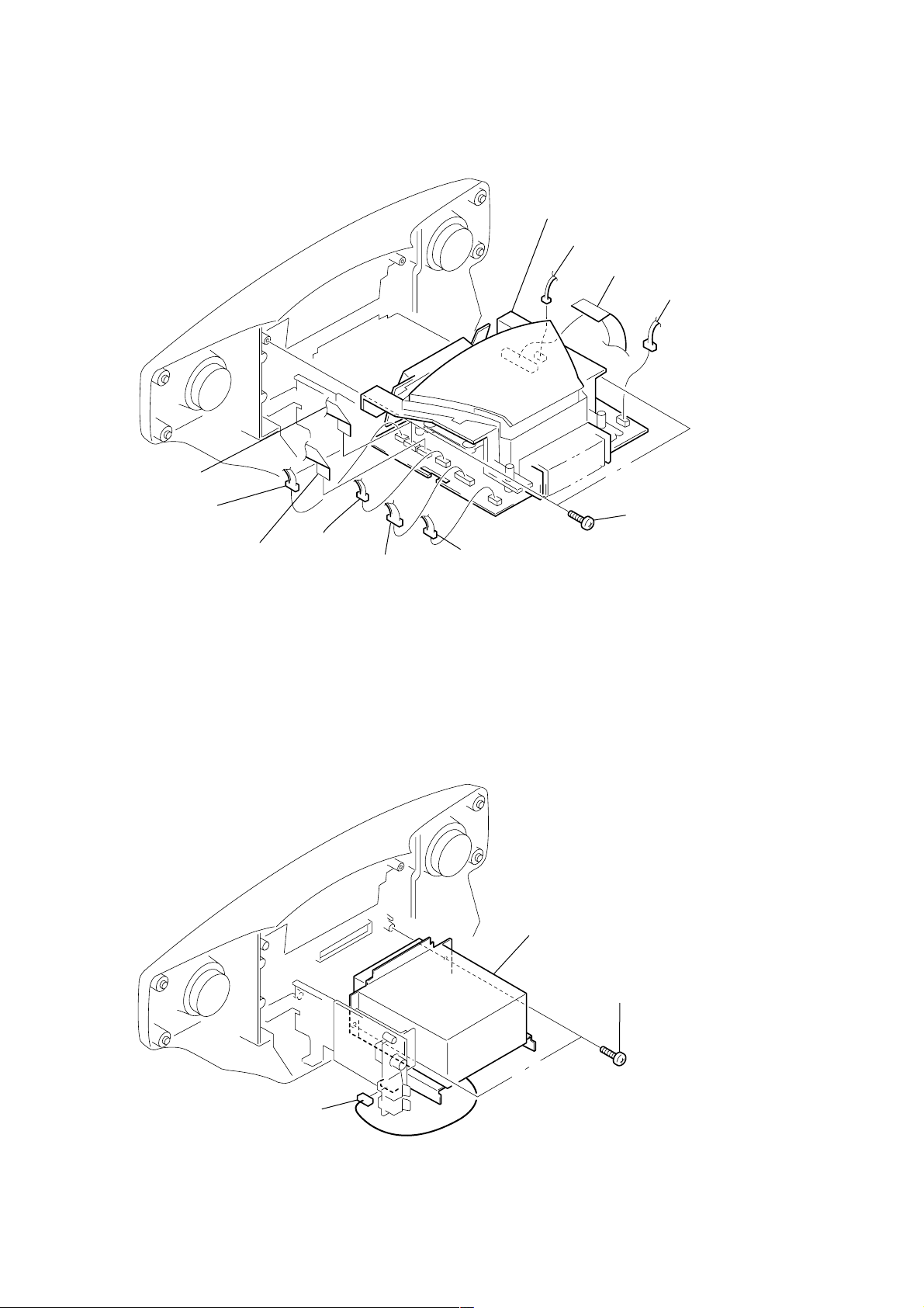
3-3. CABINET (UPPER) ASSY
4
9 CN406
qacabinet (upper) assy
2 CN705
3 CN404
4 connector
q; CN409
3-4. MD BLOCK ASSY
8 CN407
7 CN303
6 CN408
1 BVTP 3x10
5 CN301
3 MD block assy
1 CN2
2 BVTP 3x1
– 10 –

3-5. TUNER BOARD
)
8
1 BVTP 3x10
chassis (TU
4 BVTP 3x10
3-6. JACK BOARD
5 TUNER board
2 BVTP 3x10
3 BVTP 3x10
3 JACK board
– 11 –
1 BVTP 2.6x
2 CN306
3-7. LED BOARD
8
1 BVTP 2.6x8
2 BVTP 2.6x8
3 LED board
3-8. KEY BOARD
1 BVTP 2.6x
2 BVTP 2.6x8
3 KEY board
– 12 –
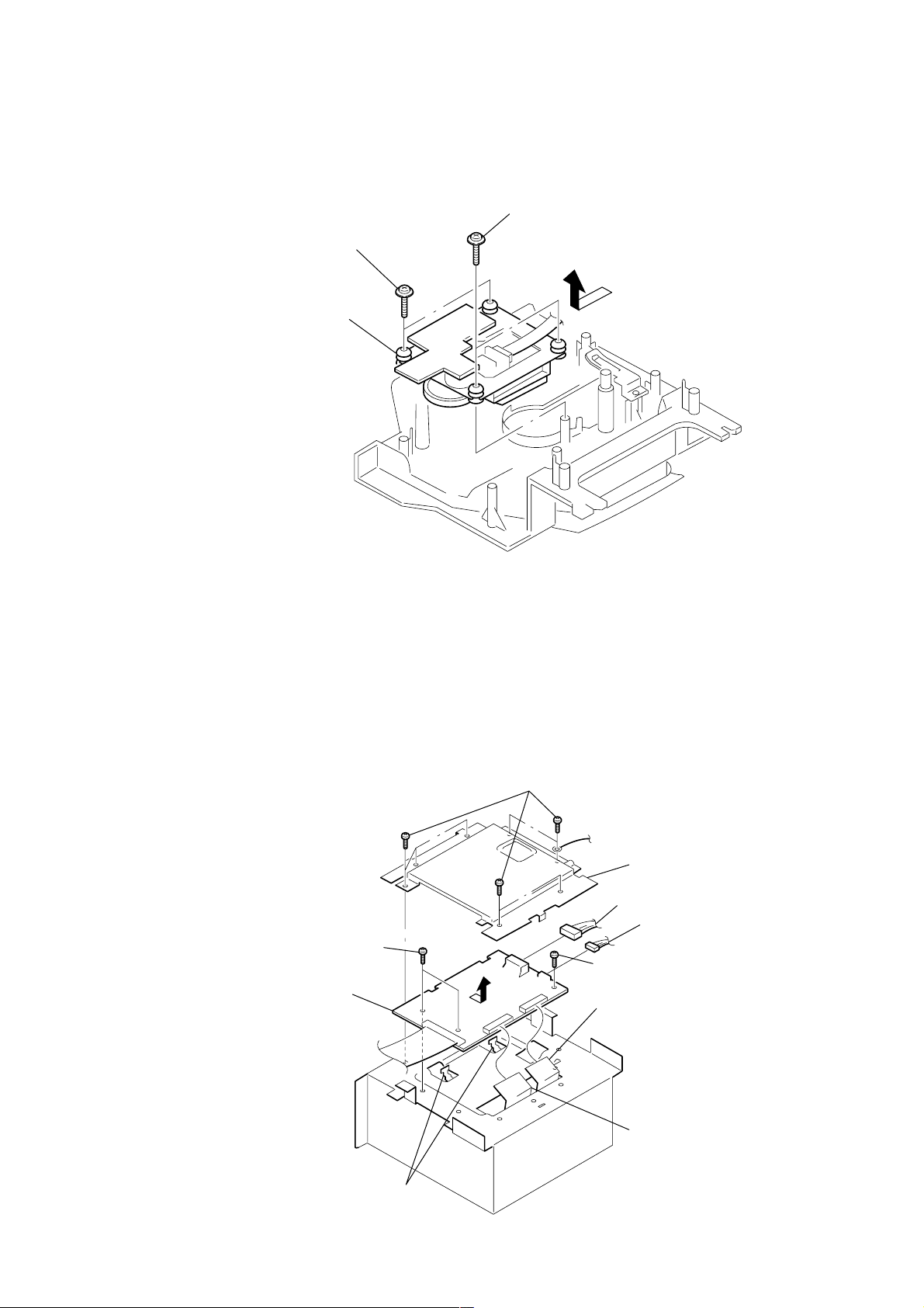
3-9. T OP BOARD
1 BVTP 2.6x8
3 BVTP 2.6x8
5 TOP board
4 button (top)
2
2 BVTP 3x10
3 FL board
1 CN405
3-10. FL BOARD
– 13 –
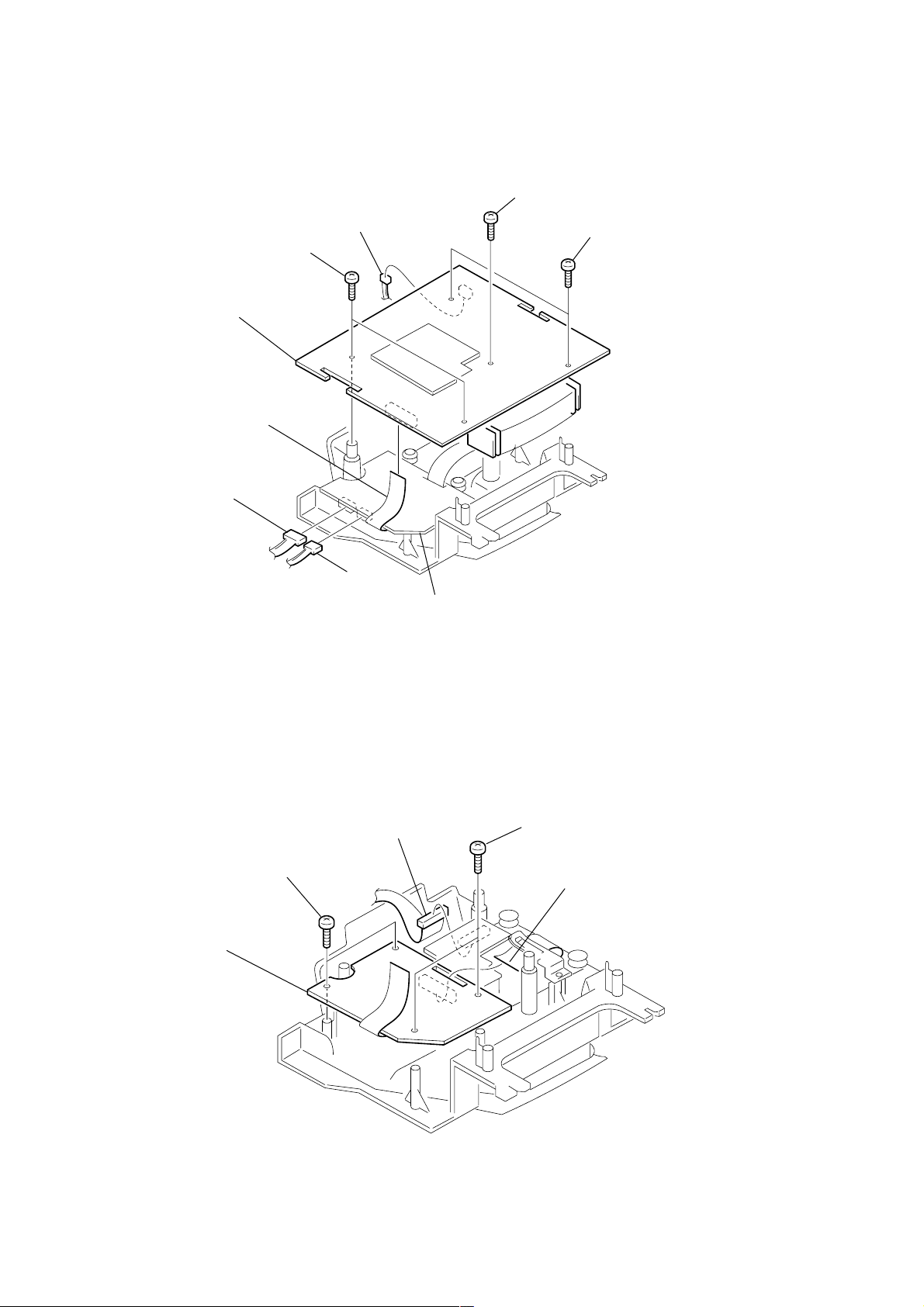
3-11. MAIN BOARD
5 BVTP 3x10
6 BVTP 3x10
8 MAIN board
7 CN403
2 CN707
1 CN410
3 CN704
4 BVTP 3x10
CD board
3-12. CD BOARD
CD board
5
BVTP 3x10
3
CN801
1
BVTP 3x10
2
4
CN701
– 14 –
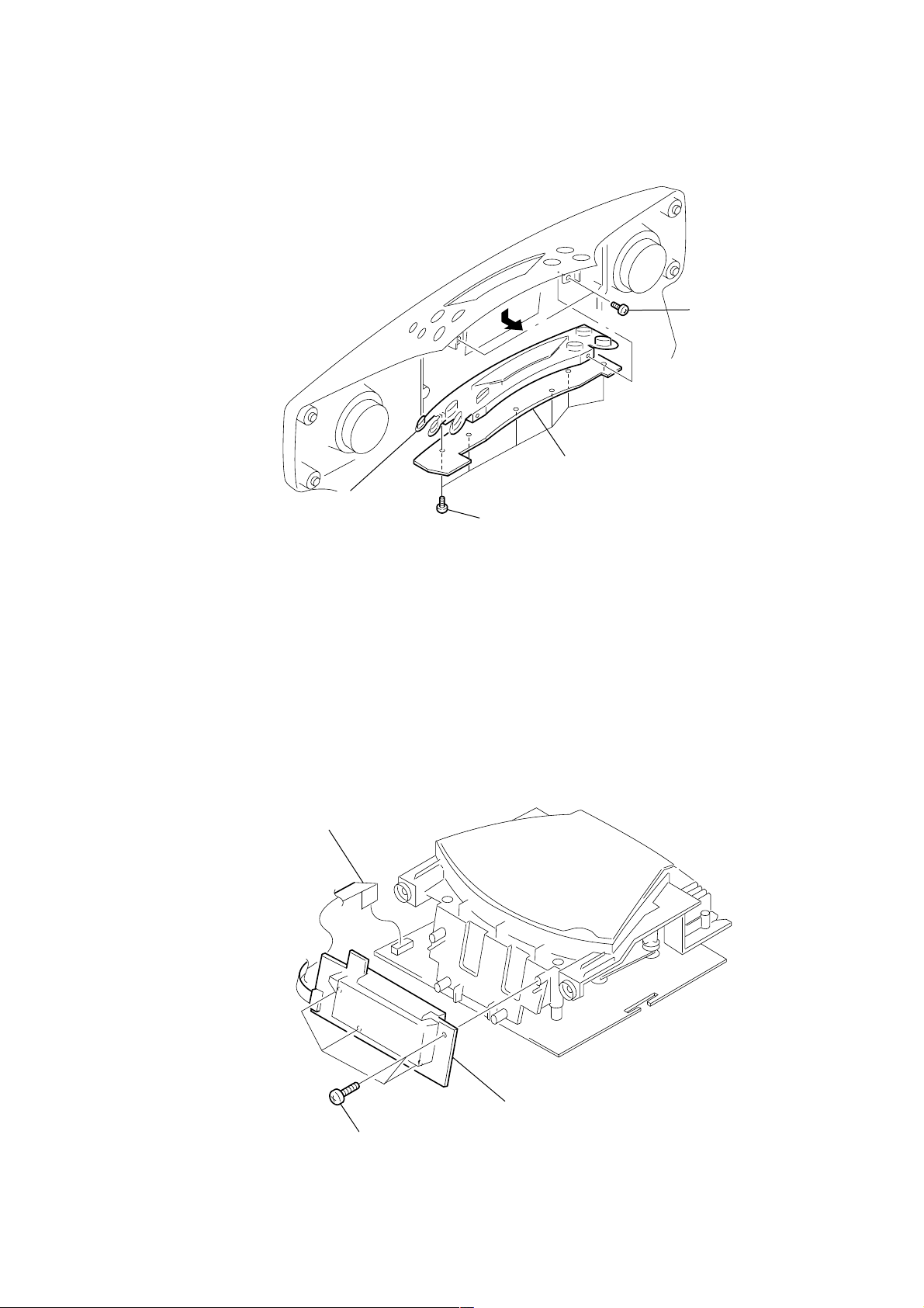
3-13. CD MECHANISM BLOCK
4 CD mechanism block
1 PWH 2.6x10
2 PWH 2.6x10
3
3-14. DG BOARD
4 P 2.6x5
q; DG board
7
1 P 2.6x5
2 plate (lower) , shield
5 CN605
6 CN603
3 P 2.6x5
8 CN602
9 CN601
claws
– 15 –
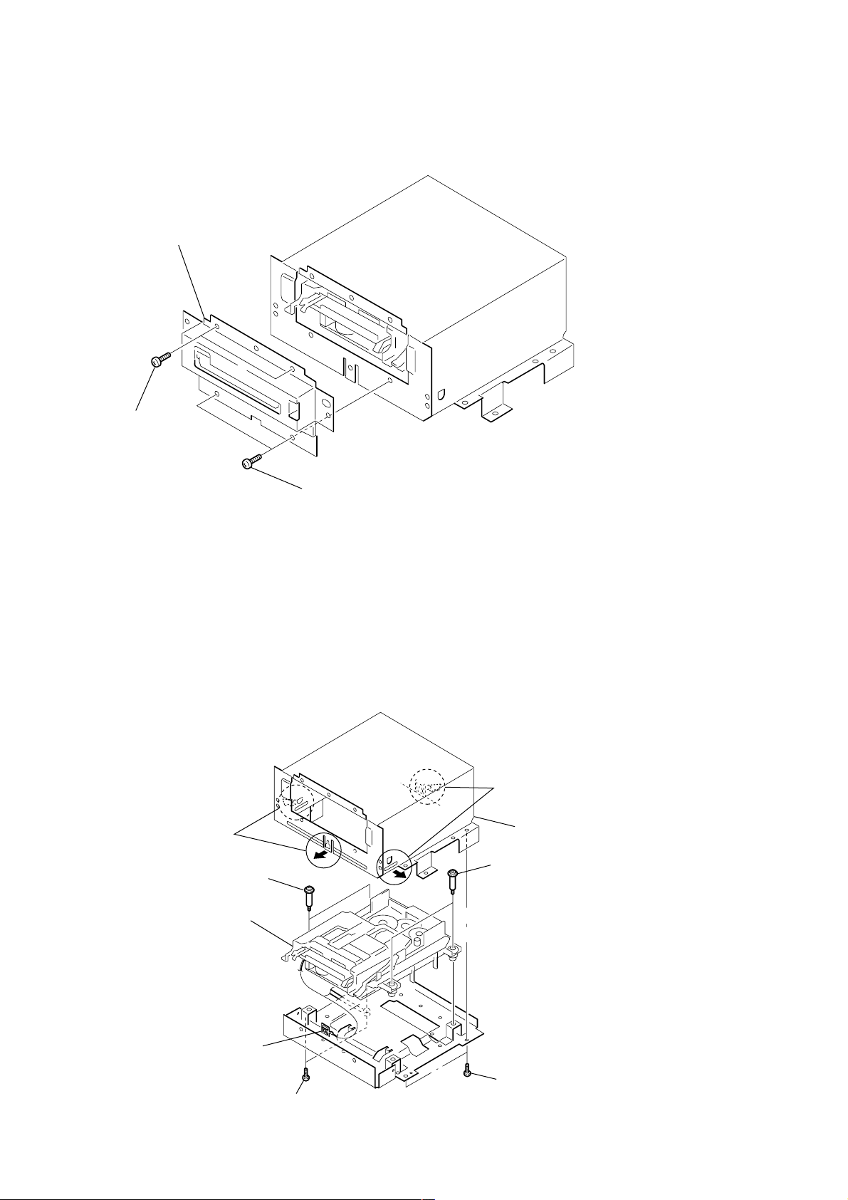
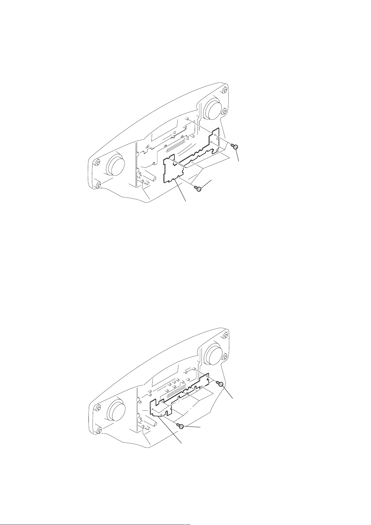
3-15. PLATE (FRONT), SHIELD
3 plate (front), shield
2 P 2.6x5
1 P 2.6x5
3-16. MD MECHANISM BLOCK-1 (MDM-5GA)
4 claws
7 BVTTWH M3
9 MD mechanism block
(MDM-5GA)
8 harnes
3 claws
5 plate (upper), shield
6 BVTTWH M3
2 P 2.6x5
1 P 2.6x5
– 16 –
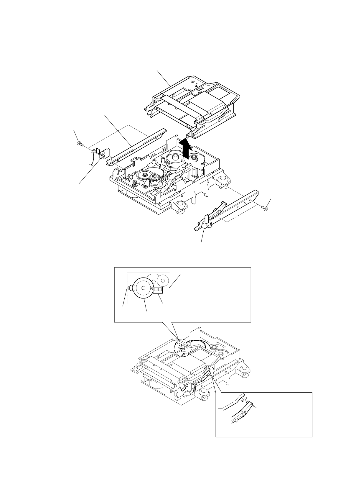
3-17. MD MECHANISM BLOCK-2 (SLIDER (CAM) ASSY)
6 slider (cam) assy
3 bracket (guide L)
1 BV 2.6 (1T3B)
2 spring, leaf
4 BV 2.6 (1T3B)
press
fitting
shaft
5 bracket (guide R)
horizontal
When assembling, set the press
fitting shaft of the cam gear
horizontal to the lever (head).
lever (head)
cam gear
A
When assembling, insert the
shaft of the lever (O/C)
with A part fit in the slot.
– 17 –
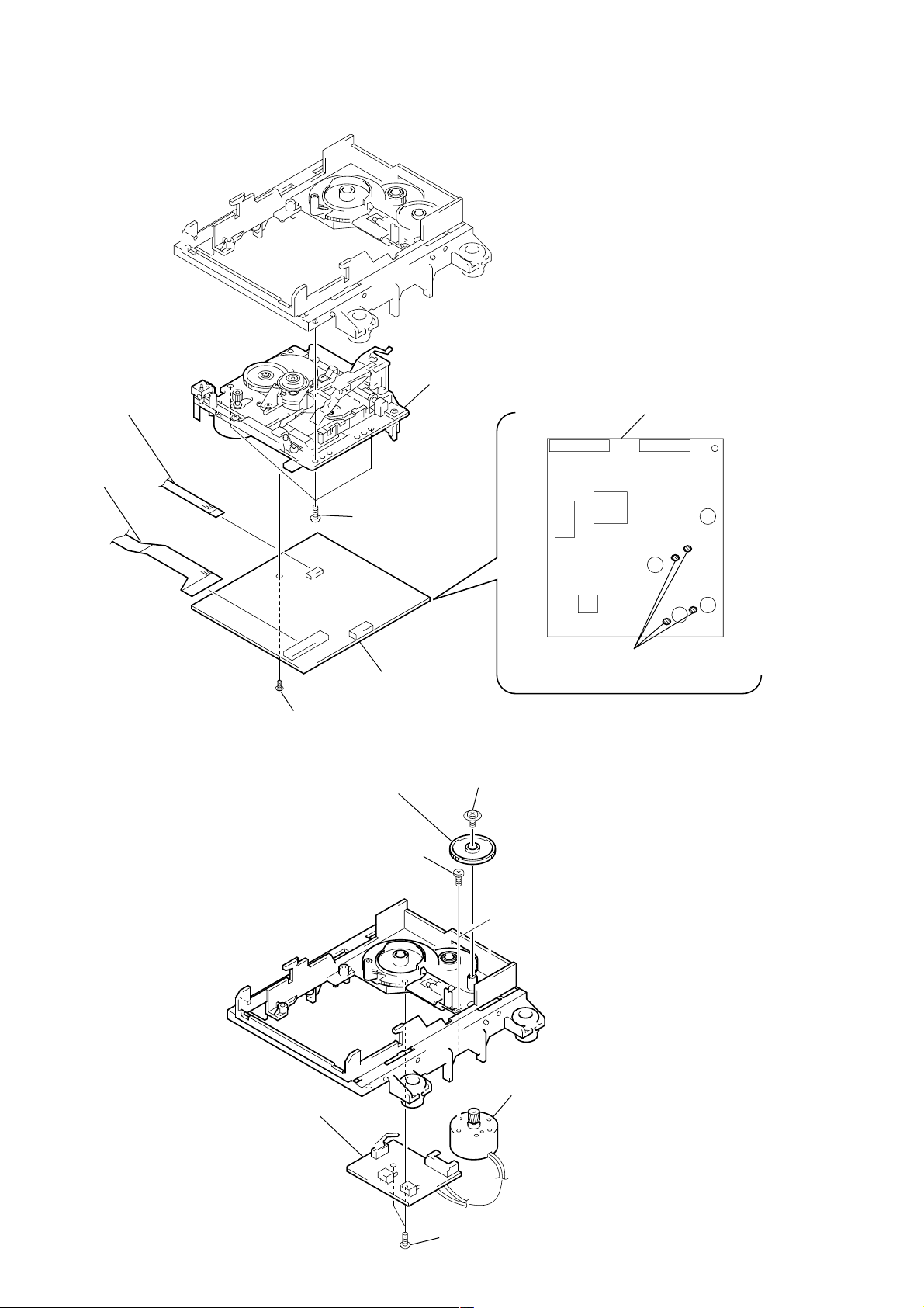
3-18. MD MECHANISM BLOCK-3 (BD BOARD)
5 CN104
6 CN101
1 BV 2.6 (1T3B)
2 MD base unit
BD board (side A)
4 M 1.7
3-19. MD MECHANISM BLOCK-4 (SW BOARD)
3 PWH 1.7x4
6 SW board
7 BD board
2 gear (B)
3 Removal the solders
1 PTPWH M 2.6x6
4 motor assy, loading
5 BTP 2.6x6
– 18 –
SECTION 4
TEST MODE
Refer to “5. ELECTRICAL ADJUSTMENT” for the test mode of CD section.
4-1. MD SECTION
1. PRECAUTIONS FOR USE OF TEST MODE
• As loading related operations will be performed regardless of the test mode operations being performed, be sure to check that the disc is
stopped before setting and removing it.
Even if the Z (MD) button is pressed while the disc is rotating during continuous playback, continuous recording, etc., the disc will not
stop rotating.
Therefore, it will be ejected while rotating.
Be sure to press the Z (MD) button after pressing the [REC/REC MODE] button and the rotation of disc is stopped.
1-1. Recording laser emission mode and operating buttons
• Continuous recording mode (CREC MODE)
• Laser power check mode (LDPWR CHECK)
• Laser power adjustment mode (LDPWR ADJUST)
• When pressing the [REC] button.
2. SETTING THE TEST MODE
1. Set to standby state.
2. Press the buttons [SOUND] and [EDIT] and . (TUNE –) at the same time and then release them soon (within 100m sec). The TEST
MODE is entered.
3. RELEASING THE TEST MODE
Hold down the [POWER] button and remove the power cord to reset the set.
4. BASIC OPERATIONS OF THE TEST MODE
All operations are performed with the following buttons: u (MD), x (MD), [RADIO/BAND], and [REC/REC MODE].
The functions of these buttons are as follows.
Function name Function
u (MD) Proceeds the parameter/mode change.
x (MD) Returns to the parameter/mode change.
RADIO/BAND Goes ahead. Determines the setting/selection.
REC/REC MODE Suspends.
5. SELECTING THE TEST MODE
There are 9 types of test modes as shown below. The groups can be switched by press the u (MD) or x (MD) button. After selecting the
group to be used, press the [RADIO/BAND] button. After setting a certain group, press the u (MD) or x (MD) button between these modes.
Display
TEMP ADJUST
LDPWR ADJUST
LDPWR CHECK
EFBAL ADJUST
FBIAS ADJUST
FBIAS CHECK
CPLAY MODE
CREC MODE
EEP MODE
Temperature compensation offset adjustment
Laser power adjustment
Laser power check
EF balance adjustment
Focus bias adjustment
Focus bias check
Continuous playback mode
Continuous recording mode
Non-volatile memory control
Contents
• For details of each adjustment mode, refer to “5. Electrical Adjustments”.
• If a different mode has been selected by mistake, press the [REC/REC MODE] button to release that mode.
• EEP MODE is not used for servicing and therefore are not described in detail. If these modes are set accidentally, press the [REC/REC MODE]
button to release the mode immediately. Be especially careful this mode will overwrite the non-volatile memory and reset it, and as a
result, the unit will not operate normally.
– 19 –

5-1. Operating the Continuous Playback Mode
1. Entering the continuous playback mode
(1) Set the disc in the unit. (Whichever recordable discs or discs for playback only are available)
(2) Press the u (MD) or x (MD) button to display “CPLAY MODE”.
(3) Press the [RADIO/BAND] button to change the display to “CPLAY MID”.
(4) When access completes, the display changes to “C1 = AD = ”.
Note: The numbers “
2. Changing the parts to be played back
(1) Press the [RADIO/BAND] button during continuous playback to change the display as below.
“CPLAY MID” t “CPLAY OUT” t “CPLAY IN”
When pressed another time, the parts to be played back can be moved.
(2) When access completes, the display changes to “C1 = AD = ”.
Note: The numbers “
3. Ending the continuous playback mode
(1) Press the [REC/REC MODE] button. The display will change to “CPLAY MODE”.
(2) Press the Z (MD) button and take out the disc.
Note: The playback start addresses for IN, MID, and OUT are as follows.
IN : 40h cluster
MID : 300h cluster
OUT: 700h cluster
5-2. Operating the Continuous Recording Mode (Use only when performing self-recording/palyback check)
1. Entering the continuous recording mode
(1) Set a recordable disc in the unit.
(2) Press the u (MD) or x (MD) button to display “CREC MODE”.
(3) Press the [RADIO/BAND] button to change the display to “CREC MID”.
(4) When access completes, the display changes to “CREC ( )” and “[REC]” lights up.
Note: The numbers “
2. Changing the parts to be recorded
(1) When the [RADIO/BAND] button is pressed during continuous recording, the display changes as below.
“CREC MID” t “CREC OUT” t “CREC IN”
” displayed show you error rates and ADER.
” displayed show you error rates and ADER.
” displayed shows you the recording position addresses.
When pressed another time, the parts to be recorded can be changed. “[REC]” goes off.
(2) When access completes, the display changes to “CREC ( )” and “[REC]” lights up.
Note: The numbers “
3. Ending the continuous recording mode
(1) Press the [REC/REC MODE] button. The display changes to “CREC MODE” and “[REC]” goes off.
(2) Press the Z (MD) button and take out the disc.
Note 1: The recording start addresses for IN, MID, and OUT are as follows.
IN : 40h cluster
MID : 300h cluster
OUT: 700h cluster
Note 2: The [REC/REC MODE] button can be used to stop recording anytime.
Note 3: Do not perform continuous recording for long periods of time above 5 minutes.
Note 4: During continuous recording, be careful not to apply vibration.
5-3. Non-Volatile Memory Mode (EEP MODE)
This mode reads and writes the contents of the non-volatile memory.
It is not used in servicing. If the unit entered this mode accidentally, press the [REC/REC MODE] button immediately to release it.
” displayed shows you the recording position addresses.
– 20 –
6. FUNCTIONS OF OTHER BUTTONS
Function
u (MD) and EDIT
x (MD) and EDIT
>
.
REC/REC MODE and EDIT
x (CD) and EDIT
RADIO/BAND and EDIT
LINE/LINE LEVEL
Z (MD)
POWER
Sets continuous playback when pressed in the STOP state. When pressed during continuous playback,
the tracking servo turns ON/OFF.
Stops continuous playback and continuous recording.
The sled moves to the outer circumference only when this is pressed.
The sled moves to the inner circumference only when this is pressed.
When pressed during continuous playback, REC ON/OFF.
Switches between the pit and groove modes when pressed.
When pressed during continuous playback, switches the spindle servo mode (CLV-S y CLV-A).
Switches the displayed contents each time the button is pressed
Ejects the disc
Releases the test mode
Contents
7. TEST MODE DISPLAYS
Each time the [LINE/LINE LEVEL] button is pressed, the display changes in the following order.
1. Mode display
Displays “TEMP ADJUST”, “CPLAYMODE”, etc.
2. Error rate display
Displays the error rate in the following way.
C1 = ssss AD = ss
C1 = Indicates the C1 error.
AD = Indicates ADER.
Mode display
Error rate display
Address display
3. Address display
The address is displayed as follows. (MO: recordable disc, CD: playback only disc)
Press the x (CD) and [EDIT] buttons at the same time to switches between the groove display
and pit display.
h = ssss s = ssss (MO pit and CD)
h = ssss a = ssss (MO groove)
h = Indicates the header address.
s = Indicates the SUBQ address.
a = Indicates the ADIP address.
Note: “–” is displayed when servo is not imposed.
4. Auto gain display (Not used in servicing)
The auto gain is displayed as follows.
AG F = ss T = ss
5. IVR display (Not used in servicing)
The IVR is displayed as follows.
[ss][ss][ss]
MEANINGS OF OTHER DISPLAYS
Display
SHUF
PGM
[REC]
TOC EDIT
TRACK
TIMER
When Lit
During continuous playback (CLV: ON)
Tracking servo OFF
Recording mode ON
ABCD adjustment completed
Pit
CLV-S
Contents
When Off
STOP (CLV: OFF)
Tracking servo ON
Recording mode OFF
Groove
CLV-A
Auto gain display
(Not used in servicing)
IVR display
(Not used in servicing)
– 21 –
)
SECTION 5
ELECTRICAL ADJUSTMENTS
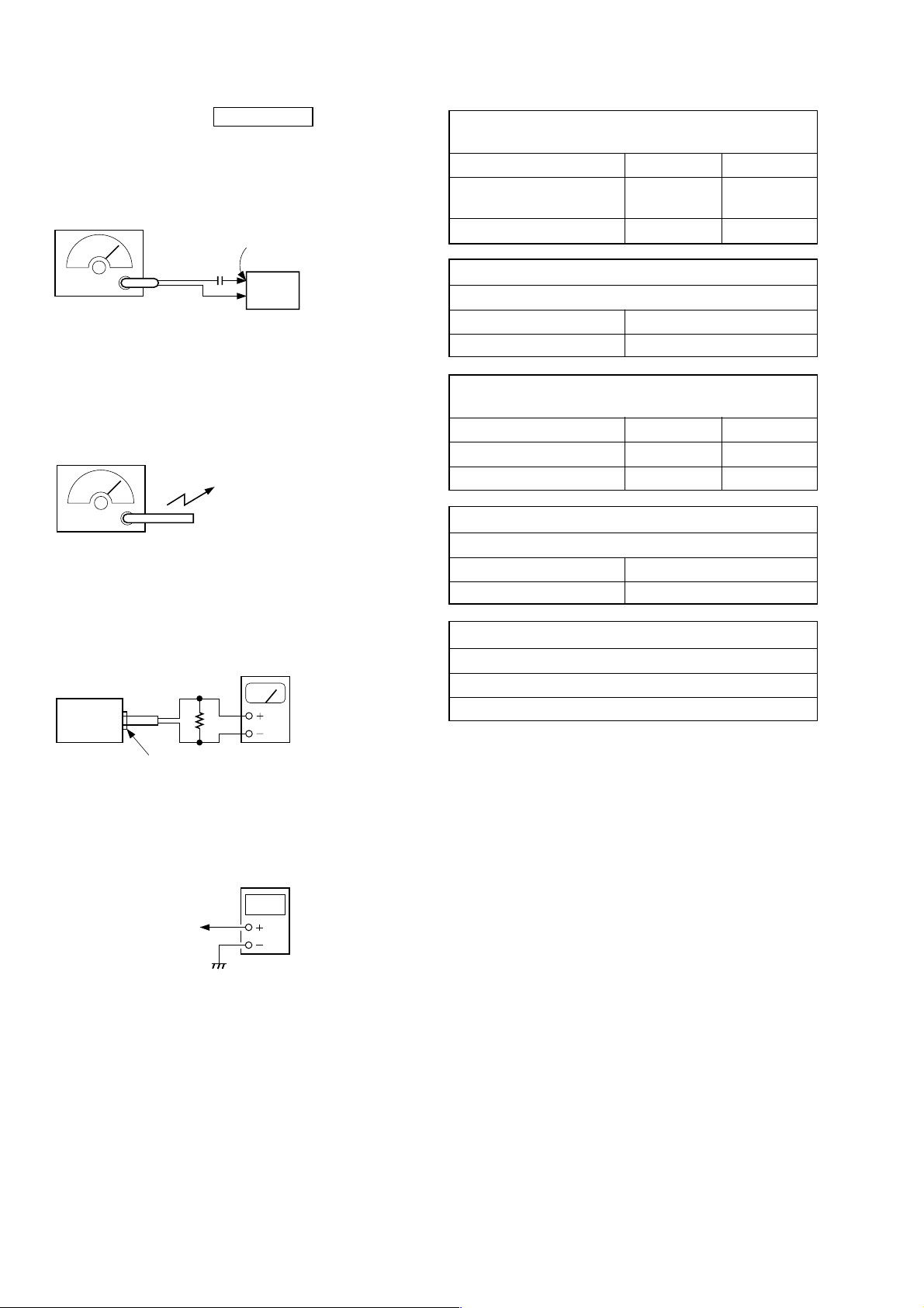
5-1. TUNER SECTION 0 dB = 1 µV
• FM Section
Setting:
BAND button: FM
FM RF signal
generator
FM antenna
(JW1,2)
0.01 µF
set
75 kHz frequency
deviation by 1 kHz signal
output level : as low as possible
• AM Section
Setting:
BAND button: AM
AM RF signal
generator
Put the lead-wire
antenna close to
the supplied
AM loop antenna.
30% amplitude
modulation by 400 Hz signal
output level : as low as possible
• Connecting Level Meter (FM and AM)
level meter
(range: 0.5-5 V ac
32 Ω
set
FM FREQUENCY COVERAGE
ADJUSTMENT
Frequency Display 87.5 MHz 108 MHz
Reading on Digital voltmeter 1.3
+ 0.4 V
– 0.2 V – 0.5 V
3.0
+ 0.3 V
Adjustment Part <confirmation> L2
FM TRACKING ADJUSTMENT
Adjust for a maximum reading on level meter.
L1 CT1
87.5 MHz 108 MHz
AM FREQUENCY COVERAGE
ADJUSTMENT
Frequency Display 530 kHz 1,710 kHz
Reading on Digital voltmeter 0.8 ± 0.2 V 5.5 ± 0.3 V
Adjustment Part <confirmation> L4
AM TRACKING ADJUSTMENT
Adjust for a maximum reading on level meter.
L3 CT2
620 kHz 1,400 kHz
AM IF ADJUSTMENT
Adjust for a maximum reading on level meter.
T1
450 kHz
i jack (J301)
• Connecting Digital Voltmeter (FM and AM)
digital
voltmeter
tuner board
TP (VT)
• Repeat the procedures in each adjustment several times, and the
frequency coverage and tracking adjustments should be finally
done by the trimmer capacitors.
Adjustment Location: TUNER board (See page 23.)
– 22 –
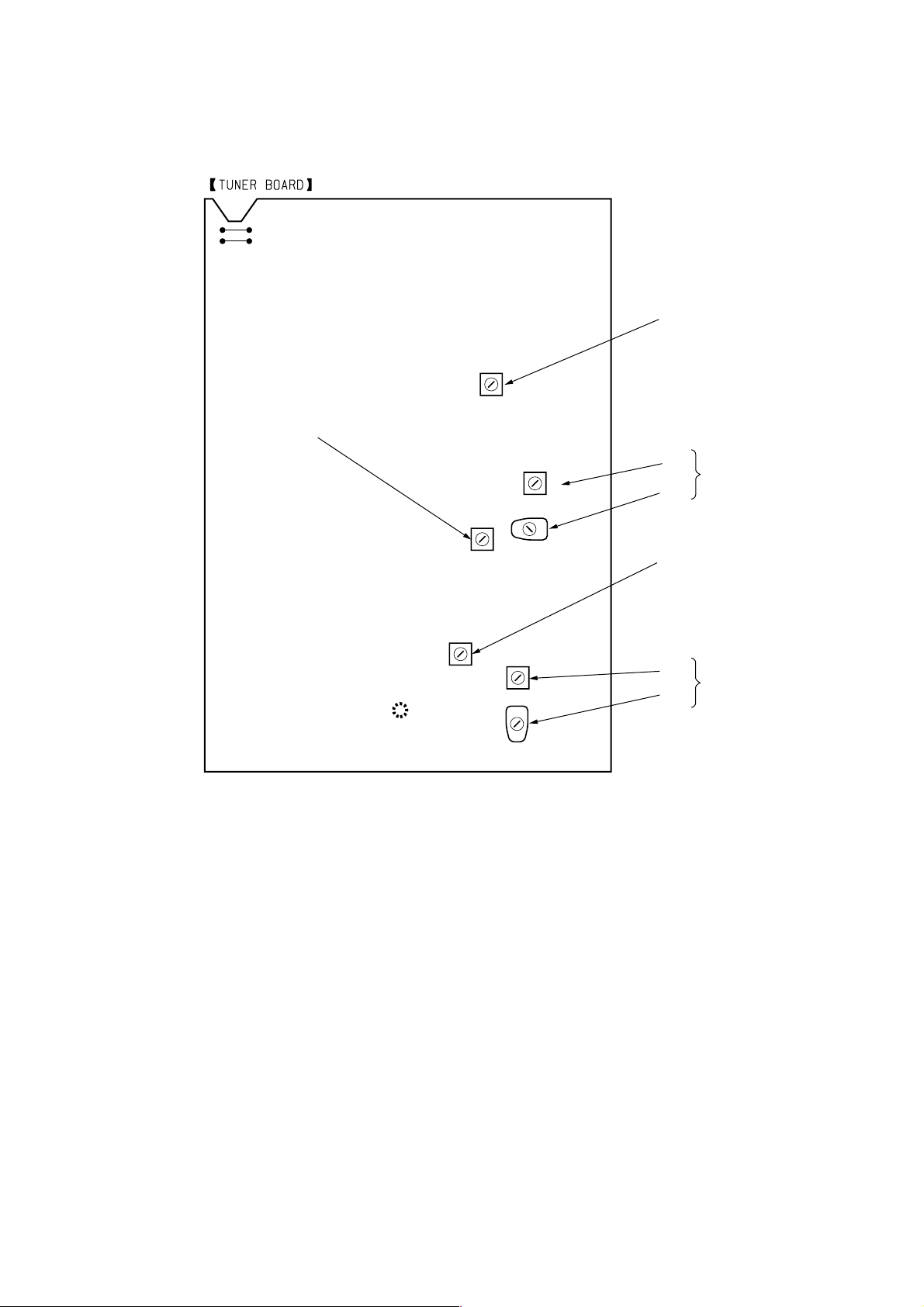
Adjustment Location:
T
FM FREQUENCY
(COMPONENT SIDE)
JW1
JW2
T1
AM IF
ADJUSTMENT
L2
COVERAGE
ADJUSTMENT
TP(VT)
L1
CT1
AM FREQUENCY
COVERAGE
ADJUSTMENT
L3
CT2
FM
TRACKING
ADJUSTMEN
L4
AM
TRACKING
ADJUSTMENT
– 23 –

5-2. MD SECTION
1. PARTS REPLACEMENT AND ADJUSTMENT
• Check and adjust the mechanism deck as follows.
The procedure changes according to the part replaced.
• Laser power check
• Focus bias check
• C PLAY check
• Self-recording/playback check
NG
Parts Replacement and Repair
• Abbreviation
OP : Optical pick-up
OWH : Overwrite head
OK
Check the sled and spindle
mechanisms.
Other causes can be suspected.
Has the OWH been replaced?
NO
Has OP, IC171, IC101, or
IC121 been replaced?
YES
Initial setting of the adjustment value
Has OP or IC171 been replaced?
YES
IOP information recording
(IOP value labeled on OP)
YES
NO
NO
Has IC171 or D101
been replaced?
YES
Temperature compensation offset adjustment
• Laser power adjustment
• Traverse adjustment
• Focus bias adjustment
• Error rate adjustment
• Focus bias check
• Auto gain adjustment
– 24 –
NO
2. PRECAUTIONS FOR CHECKING LASER DIODE
EMISSION
T o check the emission of the laser diode during adjustments, ne v er
view directly from the top as this may lose your eye-sight.
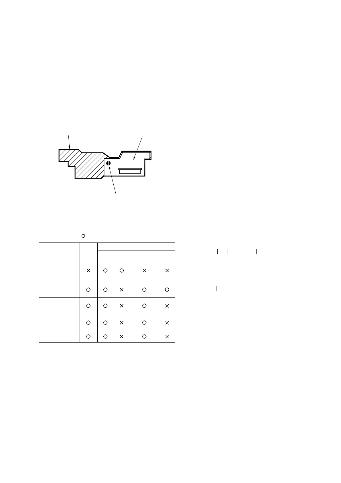
3. PRECAUTIONS FOR USE OF OPTICAL PICK-UP
(KMS-260B)
As the laser diode in the optical pick-up is easily damaged by static
electricity, solder the laser tap of the flexible board when using it.
Before disconnecting the connector, desolder first. Before connecting the connector, be careful not to remove the solder. Also take
adequate measures to prevent damage by static electricity. Handle
the flexible board with care as it breaks easily.
pick-up
laser tap
Optical pick-up flexible board
flexible board
4. Use the following tools and measuring device.
• Check Disc (MD) TDYS-1
(Part No. 4-963-646-01)
• Test Disc (MDW-74/AU-1) (Part No. 8-892-341-41)
• Laser power meter LPM-8001 (Part No. J-2501-046-A)
or MD Laser power meter 8010S (Part No. J-2501-145-A)
• Oscilloscope (Measure after performing CAL of prove)
• Digital voltmeter
• Thermometer
• Jig for checking BD board waveform
(Part No. : J-2501-149-A)
5. When observing several signals on the oscilloscope, etc., make
sure that VC and ground do not connect inside the oscilloscope.
(VC and ground will become short-circuited)
6. Using the above jig enables the waveform to be check ed without the need to solder.
(Refer to Servicing Notes on page 5)
7. As the disc used will affect the adjustment results, make sure
that not dusts nor fingerprints are attached to it.
Laser Power Meter
When performing laser power checks and adjustment (electrical
adjustment), use of the new MD laser power meter 8010S (Part No.
J-2501-145-A) instead of the conventional laser po wer meter is convenient.
It sharply reduces the time and trouble to set the laser power meter
sensor onto the objective lens of optical pick-up.
4. PRECAUTIONS FOR ADJUSTMENTS
1. When replacing the following parts, perform the adjustments
and checks with in the order shown in the following table.
Optical
Pick-up
1.Temperature
compensation
offset adjustment
2.Laser power
adjustment
3.EF balance
adjustment
4.Focus bias
adjustment
5.Error rate check
IC171 D101 IC101, IC121 IC192
2. Set the test mode when performing adjustments.
After completing the adjustments, release the test mode.
Perform the adjustments and checks in “group S” of the test
mode.
3. Perform the adjustments to be needed in the order shown.
BD Board
5. CREATING CONTINUOUSLY-RECORDED DISC
* This disc is used in focus bias adjustment and error rate check.
The following describes how to create a continuous recording
disc.
1. Insert a disc (blank disc) commercially available.
2. Press the u (MD) or x (MD) button to display “CREC
MODE”.
3. Press the [RADIO/BAND] button again to display “CREC MID”.
Display “CREC (0300)” and start to recording.
4. Complete recording within 5 minutes.
5. Press the [REC/REC MODE] button and stop recording.
6. Press the Z (MD) button and remove the disc.
The above has been how to create a continuous recorded data for
the focus bias adjustment/check and MO error rate check.
Note:
• Be careful not to apply vibration during continuous recording.
– 25 –
6. CHECK PRIOR TO REPAIRS
r
r
These checks are performed before replacing parts according to
“approximate specifications” to determine the faulty locations. For
details, refer to “Checks Prior to Parts Replacement and Adjustments” (See page 6).
6-1. Laser Power Check
Connection:
CN110 pin 5 (I +3V)
CN110 pin 4 (IOP)
Optical pick-up
objective lens
BD board
laser
power mete
digital voltmete
+
–
6-2. Focus Bias Check
Change the focus bias and check the focus tolerance amount.
Checking Procedure:
1. Load the test disc (MDW-74/AU-1).
2. Press the u (MD) or x (MD) button to display “CPLAY
MODE”.
3. Press the [RADIO/BAND] button twice to display “CPLA Y MID”.
4. Press the [REC/REC MODE] button w hen “C1 =
AD = ”
is displayed.
5. Turn the JOG dial to display “FBIAS CHECK”.
6. Press the [RADIO/BAND] button to display “ / c = ”.
The first four digits indicate the C1 error rate, the two digits
after [/] indicate ADER, and the 2 digits after [c =] indicate the
focus bias value.
Check that the C1 error is below 50 and ADER is below 2.
7. Press the [RADIO/BAND] button to display “ / b = ”.
Check that the C1 error is about 200 and ADER is below 2.
8. Press the [RADIO/BAND] button to display “ / a = ”.
Check that the C1 error is about 200 and ADER is below 2.
9. Press the [REC/REC MODE] button, then press the Z (MD)
button and take out the test disc.
Checking Procedure:
1. Set the laser power meter on the objective lens of the optical
pick-up. (When it cannot be set properly, press the . but-
ton or > button to move the optical pick-up)
Connect the digital voltmeter to CN110 pin 5 (I+3 V) and
CN110 pin 4 (IOP) on the BD board.
2. Press the u (MD) or x (MD) button to display “LDPWR
CHECK”.
3. Press the [RADIO/BAND] button once to display “LD 0.9 mW $
”. Check that the reading of the laser power meter become
0.84 to 0.92 mW.
4. Press the [RADIO/BAND] button once more to display “LD 7.0
mW $ ”. Check that the reading the laser power meter and
digital voltmeter satisfy the specified value.
Specified Value:
Laser power meter reading : 7.0 ± 0.2 mW
Digital voltmeter reading :Value on the optical pick-up label
± 10 %
(Optical pick-up label)
KMS260B
27X40
B0825
lOP=82.5 mA in this case
lOP (mA) = Digital voltmeter reading (mV)/1 (Ω)
5. Press the [REC/REC MODE] button to display “LDPWR CHECK”
and stop the laser emission.
(The [REC/REC MODE] button is effective at all times to stop
the laser emission)
Note 1: After step 4, each time the [RADIO/BAND] button is pressed, the
display will be switched “LD 0.7 mW $ ”, “LD 6.2 mW $ ”,
and “LD WP $ ”. Nothing needs to be performed here.
( = correction)
6-3. C PLAY Check
MO Error Rate Check
Checking Procedure:
1. Load the test disc (MDW-74/AU-1).
2. Press the u (MD) or x (MD) button to display “CPLAY
MODE”.
3. Press the [RADIO/BAND] button to display “CPLAY MID”.
4. The display changes to “C1 = AD = ”.
5. If the C1 error rate is below 80, check that ADER is below 2.
6. Press the [REC/REC MODE] button to stop playback, then press
the Z (MD) button and take out the test disc.
CD Error Rate Check
Checking Procedure:
1. Load the check disc (MD) TDYS-1.
2. Press the u (MD) or x (MD) button to display “CPLAY
MODE”.
3. Press the [RADIO/BAND] button twice to display “CPLA Y MID”.
4. The display changes to “C1 = AD = ”.
5. Check that the C1 error rate is below 50.
6. Press the [REC/REC MODE] button to stop playback, then press
the Z (MD) button and take out the check disc.
6-4. Self-Recording/playback Check
Prepare a continuous recording disc using the unit to be repaired
and check the error rate.
Checking Procedure:
1. Load a recordable disc (blank disc).
2. Press the u (MD) or x (MD) button to display “CREC
MODE”.
3. Press the [RADIO/BAND] button to display “CREC MID”.
4. When recording starts, lights up “[REC]” and display “CREC
@@@@” (@@@@ is the address).
5. About 1 minute later, press the [REC/REC MODE] button to stop
continuous recording.
6. Turn the JOG dial to display “CPLAY MODE”.
7. Press the [RADIO/BAND] button to display “CPLAY MID”.
8. “C1 = AD = ” will be displayed.
9. Check that the C1 error becomes below 80 and the ADER below 2.
10. Press the [REC/REC MODE] button to stop play back, then press
the Z (MD) button and take out the disc.
Note: After the TEST MODE is entered, insert the disc.
– 26 –
7. TEMPERATURE COMPENSATION OFFSET
r
r
ADJUSTMENT
Save the temperature data at that time in the non-volatile memory
as 25 °C reference data.
Note:
1. Usually, do not perform this adjustment.
2. Perform this adjustment in an ambient temperature of 22 °C to 28 °C.
Perform it immediately after the power is turned on when the internal
temperature of the unit is the same as the ambient temperature of 22 °C
to 28 °C.
3. When D101 has been replaced, perform this adjustment after the temperature of this part has become the ambient temperature.
Adjusting Procedure:
1. Press the u (MD) or x (MD) button to display “TEMP
ADJUST”.
2. Press the [RADIO/BAND] button to select the “TEMP ADJUST”
mode.
3. “TEMP = ” and the current temperature data will be displayed.
4. To save the data, press the [RADIO/BAND] button.
When not saving the data, press the [REC/REC MODE] button.
5. When the [RADIO/BAND] button is pressed, “TEMP = SA VE”
will be displayed and turned back to “TEMP ADJUST” display
then. When the [REC/REC MODE] button is pressed, “TEMP
ADJUST” will be displayed immediately.
Specified V alue:
The “TEMP = ” should be within “E0 - EF”, “F0 - FF”, “00 0F”, “10 - 1F” and “20 - 2F”.
7. Then, press the u (MD) or x (MD) to display “LDPWR
CHECK”.
8. Press the [RADIO/BAND] button once to display “LD 0.9mW $
”. Check that the reading of the laser power meter become
0.85 to 0.91 mW.
9. Press the [RADIO/BAND] button once more to display “LD 7.0
mW $
”. Check that the reading the laser power meter and
digital voltmeter satisfy the specified value.
Note down the digital voltmeter reading value.
Specified Value:
Laser power meter reading : 7.0 ± 0.2 mW
Digital voltmeter reading :Value on the optical pick-up label
± 10%
(Optical pick-up label)
KMS260B
27X40
B0825
lOP=82.5 mA in this case
lOP (mA) = Digital voltmeter reading (mV)/1 (Ω)
10. Press the [REC/REC MODE] button to display “LDPWR CHECK”
and stop the laser emission.
(The [REC/REC MODE] button is effective at all times to stop
the laser emission)
8. LASER POWER ADJUSTMENT
Connection:
Optical pick-up
objective lens
BD board
CN110 pin 5 (I +3V)
CN110 pin 4 (IOP)
Adjusting Procedure:
1. Set the laser power meter on the objective lens of the optical
pick-up. (When it cannot be set properly, pr ess the . but-
ton or > button to move the optical pick-up)
Connect the digital voltmeter to CN110 pin 5 (I+3 V) and
CN110 pin 4 (IOP) on the BD board.
2. Press the u (MD) or x (MD) button to display “LDPWR
ADJUST”.
(Laser power: For adjustment)
3. Press the [RADIO/BAND] button once to display “LD 0.9 mW $
”.
4. Press the u (MD) or x (MD) button so that the reading of
the laser power meter becomes 0.85 to 0.91 mW. Press the
[RADIO/BAND] button after setting the range knob of the laser
power meter, and save the adjustment results. (“LD SAVE $
” will be displayed for a moment)
5. Then “LD 7.0 mW $ ” will be displayed.
6. Press the u (MD) or x (MD) button and adjust so that the
reading on the laser power meter is 6.9 to 7.1 mV. Press the
[RADIO/BAND] button to save the setting.
laser
power mete
digital voltmete
+
–
Note 1: After step 9, each time the [RADIO/BAND] button is pressed, the
display will be switched “LD 0.7 mW $ ”, “LD 6.2 mW $ ”,
and “LD WP $ ”. Nothing needs to be performed here.
( = correction)
Note: Do not perform the emission with 7.0 mW more than 15 seconds
continuously.
– 27 –
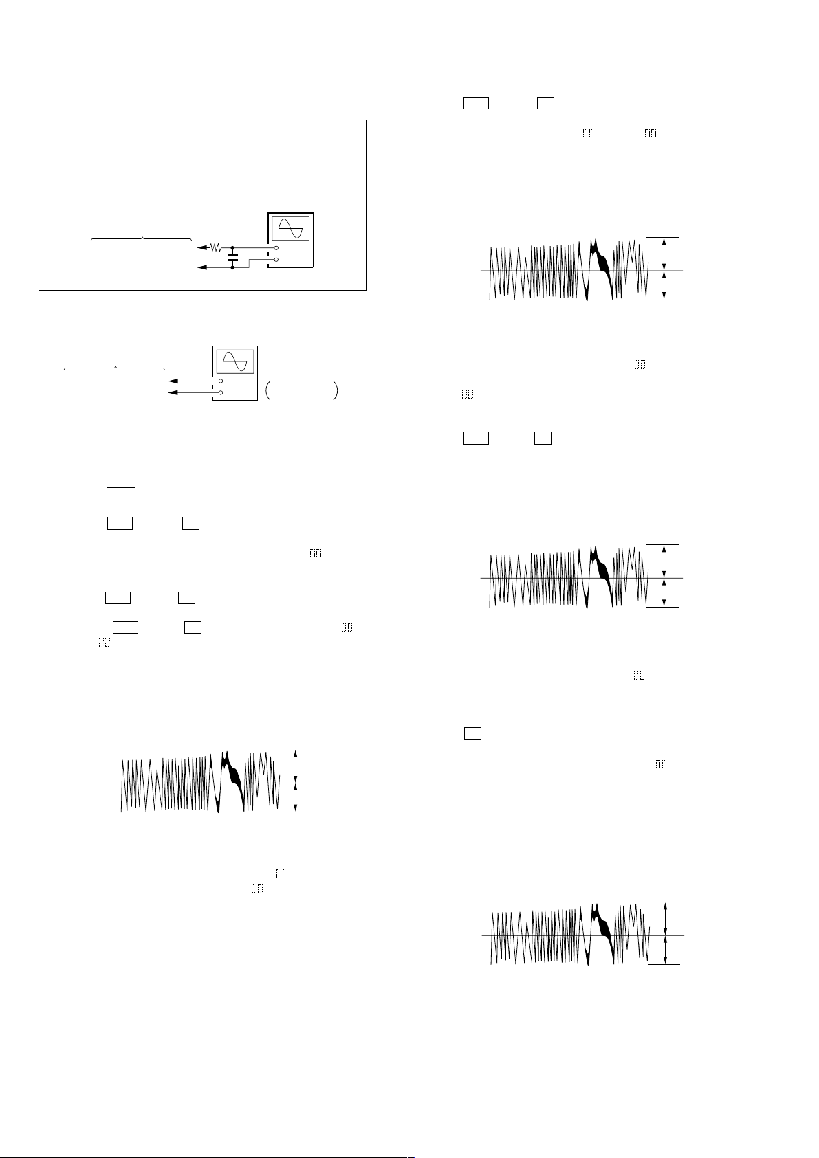
9. EF BALANCE ADJUSTMENT
Note 1: Data will be erased during MO reading if a recorded disc is
Note 2: If the traverse waveform is not clear, connect the oscilloscope
used in this adjustment.
as shown in the following figure so that it can be seen more
clearly.
BD board
CN110 pin 3 (TEO)
CN110 pin 1 (VC)
330 k Ω
10 pF
oscilloscope
(DC range)
+
–
8. Press the u (MD) or x (MD) button so that the waveform
of the oscilloscope becomes the specified value.
(When the JOG dial is turned, the of “EFB- ” changes and
the waveform changes) In this adjustment, waveform varies at
intervals of approx. 2%. Adjust the wa veform so that the specified value is satisfied as much as possible.
(Write power traverse adjustment)
Traverse Wa vef orm
A
VC
B
Connection:
oscilloscope
(DC range)
BD board
CN110 pin 3 (TEO)
CN110 pin 1 (VC)
+
–
V: 0.1 V/div
H: 10 ms/div
Adjusting Procedure:
1. Connect an oscilloscope to CN110 pin 3 (TEO) and CN110
pin 1 (VC) on the BD board.
2. Load a disc (any available on the market). (Refer to Note 1)
3. Press the > button to move the optical pick-up outside the
pit.
4. Press the u (MD) or x (MD) button to display “EFBAL
ADJUST”.
5. Press the [RADIO/BAND] button to display “EFB =
MO-R”.
(Laser power READ power/Focus serv o ON/tracking servo OFF/
spindle (S) servo ON)
6. Press the u (MD) or x (MD) button so that the wav eform
of the oscilloscope becomes the specified value.
(When the u (MD) or x (MD) button is pressed, the of
“EFB = ” changes and the waveform changes ) In this adjustment, waveform varies at intervals of approx. 2 %. Adjust the
waveform so that the specified value is satisfied as much as
possible.
(Read power traverse adjustment)
Traverse Wav ef orm
A
VC
B
Specification A = B
7. Press the [RADIO/BAND] button and save the result of adjustment to the non-volatile memory. (“EFB = SAVE” will be
displayed for a moment. Then “EFB = MO-W” will be displayed)
Specification A = B
9. Press the [RADIO/BAND] button, and save the adjustment results in the non-volatile memory. (“EFB = SAVE” will be
displayed for a moment)
10. “EFB = MO-P” will be displayed.
The optical pick-up moves to the pit area automatically and
servo is imposed.
11. Press the u (MD) or x (MD) button until the waveform of
the oscilloscope moves closer to the specified value.
In this adjustment, waveform varies at interv als of approx. 2%.
Adjust the waveform so that the specified value is satisfied as
much as possible.
Traverse Wa vef orm
A
VC
B
Specification A = B
12. Press the [RADIO/BAND] button, and save the adjustment results in the non-volatile memory. (“EFB = SABE” will be
displayed for a moment)
Next “EFBAL ADJUST” is displayed. The disc stops rotating
automatically.
13. Press the Z (MD) button and take out the disc.
14. Load the check disc (MD) TDYS-1.
15. Press the [RADIO/BAND] button to display “EFB = CD”. Servo
is imposed automatically.
16. Turn the JOG dial so that the waveform of the oscilloscope
moves closer to the specified value.
In this adjustment, waveform varies at interv als of approx. 2%.
Adjust the waveform so that the specified value is satisfied as
much as possible.
Traverse Wa vef orm
A
VC
B
– 28 –
Specification A = B
17. Press the [RADIO/BAND] button, display “EFB = SAVE” for
a moment and save the adjustment results in the non-volatile
memory.
Next “EFBAL ADJUST” will be displayed.
18. Press the Z (MD) button and take out the disc.
10. FOCUS BIAS ADJUSTMENT
Adjusting Procedure:
1. Load the continuously-recorded disc. (Refer to “5. CREA TING
CONTINUOUSLY-RECORDED DISC”)
2. Press the u (MD) or x (MD) button to display “CPLAY
MODE”.
3. Press the [RADIO/BAND] button to display “CPLAY MID”.
4. Press the [REC/REC MODE] button when “C1 = AD = ”
is displayed.
5. Press the u (MD) or x (MD) button to display “FBIAS
ADJUST”.
6. Press the [RADIO/BAND] button to display “ / a = ”.
The first four digits indicate the C1 error rate, the two digits
after [/] indicate ADER, and the 2 digits after [a =] indicate the
focus bias value.
7. Turn the JOG dial clockwise and find the focus bias value at
which the C1 error rate becomes about 200 (Refer to Note 2).
8. Press the [RADIO/BAND] button to display “ / b = ”.
9. Press the u (MD) or x (MD) button counterclockwise and
find the focus bias value at which the C1 error rate becomes
about 200.
10. Press the [RADIO/BAND] button to display “ / c = ”.
11. Check that the C1 error rate is below 50 and ADER is 00. Then
press the [RADIO/BAND] button.
12. If the “( )” in “ - - ( )” is above 20, press the
[RADIO/BAND] button.
If below 20, press the [REC/REC MODE] button and repeat the
adjustment from step 2.
13. Press the Z (MD) button and take out the disc.
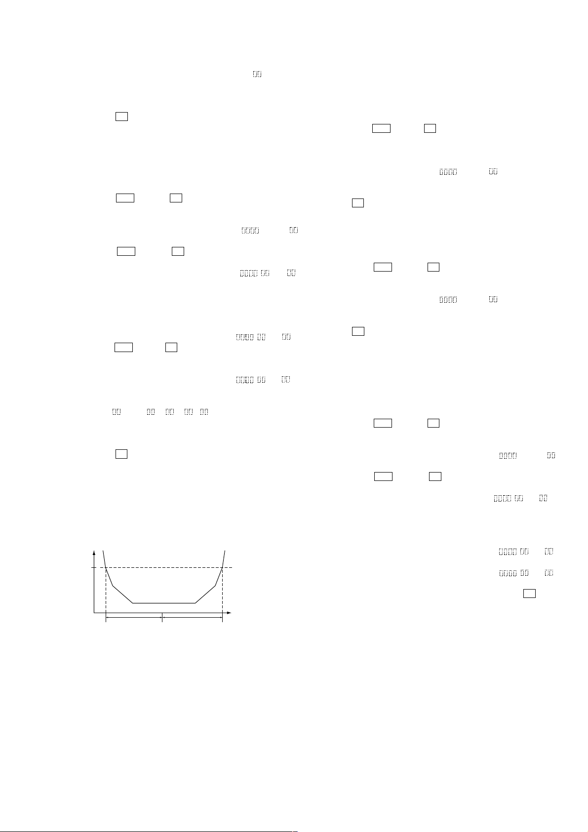
Note 1: The relation between the C1 error and focus bias is as shown in
the following figure. Find points A and B in the following figure
using the above adjustment. The focal point position C is automatically calculated form points A and B.
Note 2: As the C1 error rate changes, perform the adjustment using the
average value.
C1 error
about
200
11. ERROR RATE CHECK
11-1. CD Error Rate Check
Checking Procedure:
1. Load the check disc (MD) TDYS-1.
2. Press the u (MD) or x (MD) button and display “CPLAY
MODE”.
3. Press the [RADIO/BAND] button twice and display “CPLAY
MID”.
4. The display changes to “C1 = AD = ”.
5. Check that the C1 error rate is below 20.
6. Press the [REC/REC MODE] button to stop playback, then press
the Z (MD) button and take out the check disc.
11-2. MO Error Rate Check
Checking Procedure:
1. Load the continuously-recorded disc. (Refer to “5. CREA TING
CONTINUOUSLY-RECORDED DISC”)
2. Press the u (MD) or x (MD) button to display “CPLAY
MODE”.
3. Press the [RADIO/BAND] button to display “CPLAY MID”.
4. The display changes to “C1 = AD = ”.
5. If the C1 error rate is below 50, check that ADER is 00.
6. Press the [REC/REC MODE] button to stop playback, then press
the Z (MD) button and take out the test disc.
12. FOCUS BIAS CHECK
Change the focus bias and check the focus tolerance amount.
Checking Procedure:
1. Load the continuously-recorded disc. (Refer to “5. CREATING CONTINUOUSLY-RECORDED DISC”)
2. Press the u (MD) or x (MD) button to display “CPLAY
MODE”.
3. Press the [RADIO/BAND] button twice to display “CPLA Y MID”.
4. Press the [REC/REC MODE] button when “C1 = AD = ”
is displayed.
5. Press the u (MD) or x (MD) button to display “FBIAS
CHECK”.
6. Press the [RADIO/BAND] button to display “ / c = ”.
The first four digits indicate the C1 error rate, the two digits
after [/] indicate ADER, and the 2 digits after [c =] indicate the
focus bias value.
Check that the C1 error is below 50 and ADER is below 2.
7. Press the [RADIO/BAND] button and display “ / b = ”.
Check that the C1 error is about 200 and ADER is below 2.
8. Press the [RADIO/BAND] button and display “ / a = ”.
Check that the C1 error is about 200 and ADER is below 2.
9. Press the [REC/REC MODE] button, then press the Z (MD)
button and take out the disc.
B
C A Focus bias value
(F. BIAS)
Note 1: If the C1 error and ADER are above other than the specified value
at points A (step 8. in the above) or B (step 7. in the above), the
focus bias adjustment may not have been carried out properly.
Adjust perform the beginning again.
– 29 –
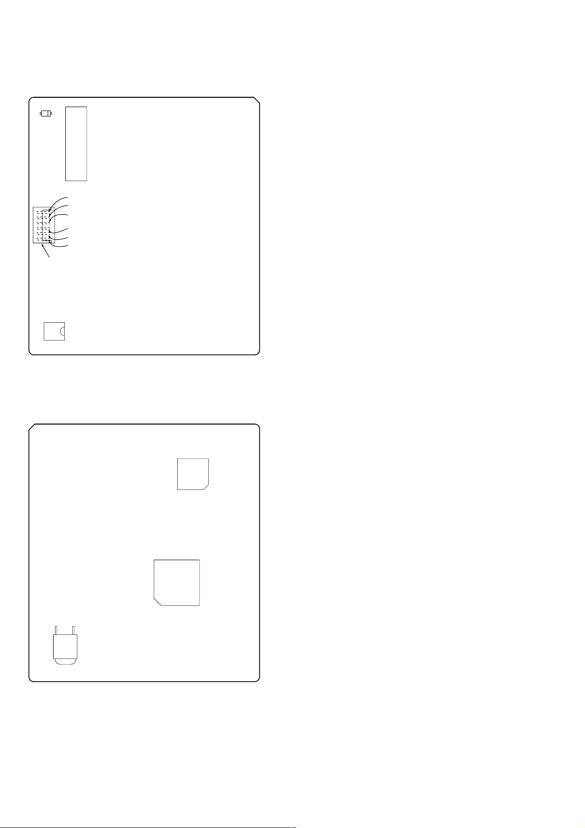
Adjustment Location:
– BD BOARD (COMPONENT SIDE) –
CN101
D101
CN110
GND
I+3V
IOP
TEO
RF
VC
NOTE
IC171
– BD BOARD (CONDUCTOR SIDE) –
IC101
IC121
IC192
Note: It is useful to use the jig for checking the waveform. (Refer to Ser-
vicing Notes on page 5)
– 30 –
 Loading...