

Sony ZRD-1, ZRCT-100, ZRD-2, ZRCT-200 Operating Instructions Manual

Display Unit
4-692-870-12 (1)
Display Controller
Operating Instructions
Before operating the unit, please read this manual and the supplied Before Using this
Unit document thoroughly and retain it for future reference.
ZRD-1
ZRCT-100
© 2016 Sony Corporation

Table of Contents
Please Read This First .............................................. 3
Manual Structure ................................................... 3
Licenses ................................................................. 3
Condensation ......................................................... 3
Security .................................................................. 3
Burn-in ................................................................... 3
Defective pixels ..................................................... 3
General Precautions ............................................... 3
Overview .................................................................... 4
System Configuration Diagram ............................. 4
Parts Identification ................................................... 5
ZRD-1 Display Unit .............................................. 5
ZRCT-100 Display Controller ............................... 6
Turning the Power On/Off ....................................... 8
Turning the Power On ............................................ 8
Turning the Power Off ........................................... 9
Selecting the Video Input ......................................... 9
Changing the Display Starting Positions of
Pictures .............................................................. 10
Adjusting the Picture Quality ................................ 11
Displaying 3D Video ................................................ 12
Troubleshooting ....................................................... 13
Error Codes ............................................................. 15
Display Units ....................................................... 15
Display Controllers .............................................. 16
Cleaning and Storage .............................................. 17
Display Units ....................................................... 17
Display Controllers .............................................. 17
Signal Formats ........................................................ 17
Trademarks
Products or system names appearing in this document are
trademarks or registered trademarks of their respective
owners.
Further, the ® or ™ symbols are not used in the text.
• Reproduction or duplication, in whole or part, of the
operation manual supplied with the system without the
authorization of the right holder is prohibited under
copyright law.
• Sony assumes no responsibility for damages, loss of
income, or any claims from a third party arising out of
use of the system.
• Note that the specifications of the system are subject to
change for improvement without prior notice.
2

Please Read This First
Manual Structure
This product includes the following manuals to be used
according to the situation.
Before Using this Unit (ZRD-1, ZRCT-100)
This includes important safety precautions, specifications,
etc.
Installation Manual
This includes information on installation, initial setup,
equipment adjustment procedures, etc. Refer to this
manual when changing equipment settings or performing
readjustments after installation as well.
Operating Instructions (this document)
This includes information on video input selection, picture
quality adjustment, parts identification, etc. Refer to this
manual when performing general operations.
Service Manual
This is intended for use by service personnel and includes
information on diagnosing malfunctions and instructions
on repair.
Licenses
Refer to the Software License Agreement.
Burn-in
Permanent burn-in may occur if a still image is displayed
for a prolonged period of time. Playing a video with
moving images may reduce the severity of burn-in once it
occurs, but it will not remove the burn-in completely.
Defective pixels
The panel fitted to this unit is manufactured with high
precision technology, giving a functioning pixel ratio of at
least 99.99%. Thus a very small proportion of pixels may
be “stuck,” either always off (black), always on (red, green,
or blue), or flashing. In addition, such “stuck” pixels may
appear spontaneously over a long period of use due to the
physical characteristics of the organic light-emitting
diodes.
Such occurrences do not indicate a malfunction.
General Precautions
• Avoid getting the product wet. In the event of accidental
contact with liquids, do not turn on the power, and
contact a service representative.
• If an error or malfunction occurs or if foreign matter
enters the interior of the product, turn off the power and
discontinue use, and contact a service representative.
• Do not subject the front panel of the display units to
damage or shocks.
• Request cleaning and maintenance periodically from a
service representative.
Condensation
If the product is suddenly taken from a cold to a warm
location, or if ambient temperature suddenly rises,
moisture may form on the outer surface and/or inside of the
product. This is known as condensation. If condensation
occurs, turn off the product and wait until the condensation
clears before operating the product. Operating the product
while condensation is present may damage the product.
Security
SONY WILL NOT BE LIABLE FOR DAMAGES OF
ANY KIND RESULTING FROM A FAILURE TO
IMPLEMENT PROPER SECURITY MEASURES ON
TRANSMISSION DEVICES, UNAVOIDABLE DATA
LEAKS RESULTING FROM TRANSMISSION
SPECIFICATIONS, OR SECURITY PROBLEMS OF
ANY KIND.
Depending on the operating environment, unauthorized
third parties on the network may be able to access the
product. When connecting the product to the network, be
sure to confirm that the network is protected securely.
3
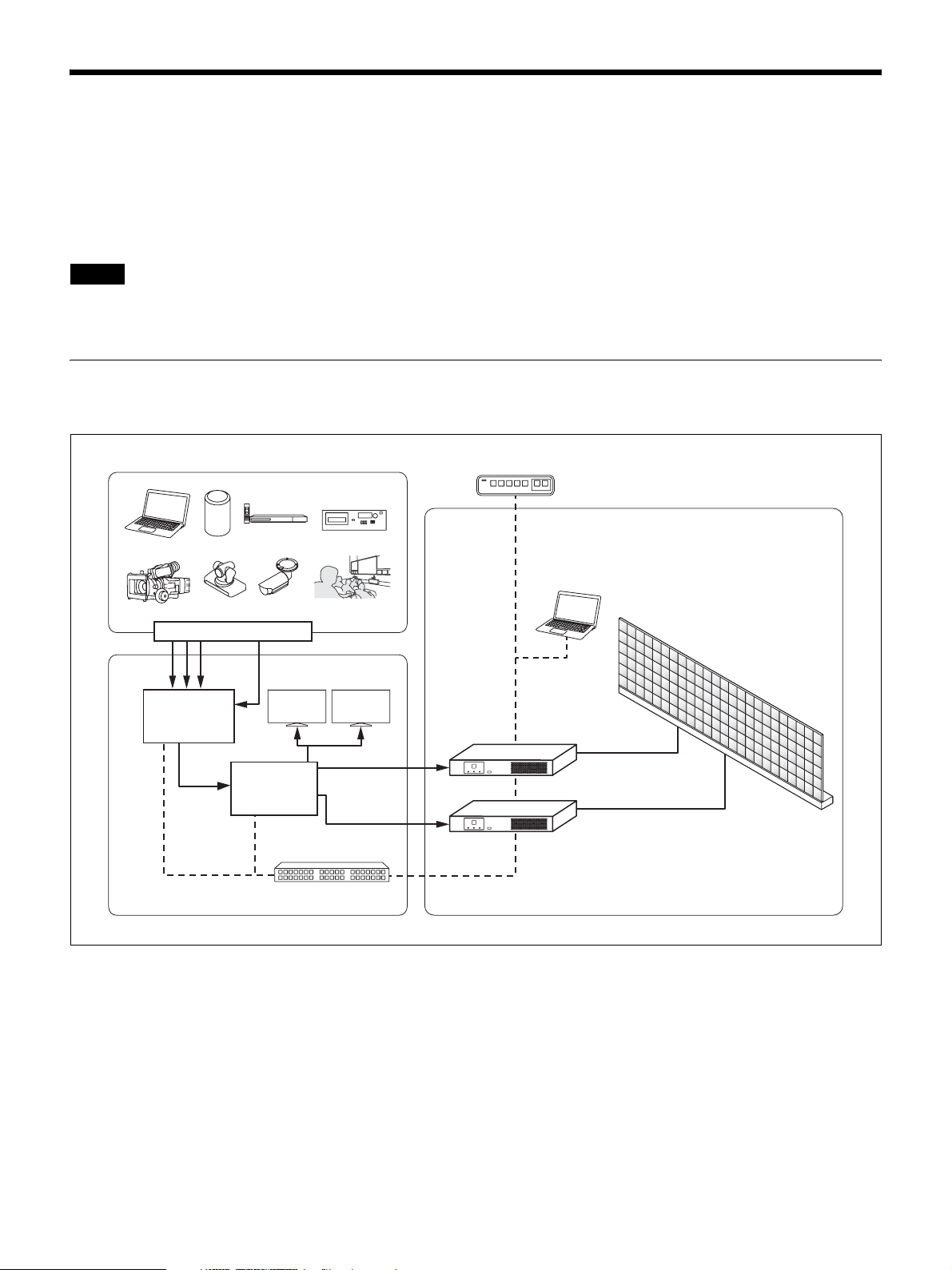
Overview
You can connect the display units based on the installation location and intended use, convert the video content signals that
are input to the display controller based on the array size, and output the signals onto the display units. 4K2K video can
be controlled via a single display controller. Control of the display units is performed from a computer on which Display
Control Software is installed.
Daisy-chain connections between display units can be configured using power cords (not supplied) and Category 7 cables
(not supplied). (For details on the number of display units that can be connected, refer to the Installation Manual.)
Notes
• Display of 4K2K video requires 72 display units.
• Each display controller is equipped with 12 ports, and each port is capable of controlling up to 6 display units.
System Configuration Diagram
Configuration example of the entire system
VPN router
Controller PC
(Display Control Software installed)
Video content transmitters
Production monitors
Matrix
switcher
Video
processor
Control (LAN)
Control (LAN)
DisplayPort
or DVI
connector
Hub
Array
(display units)
Display controller
Display controller
4
Parts Identification
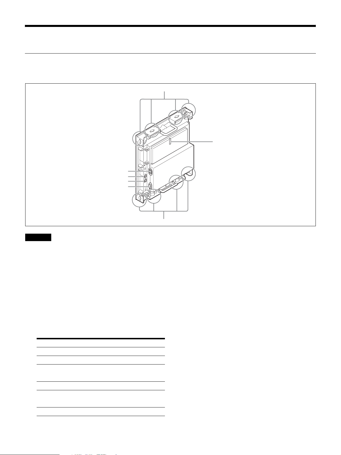
ZRD-1 Display Unit
Left / rear
a
b
f
e
d
c
Caution
Do not connect the OUT and IN connectors to a hub. The
input/output signals for these connectors are unique to the
product and are not Ethernet signals. In particular, be
aware that connecting these connectors to a PoE injector
hub may result in damage to the product.
a Unit joints
Connect to other display units.
Two unit joints are located on each of the top, bottom,
left, and right sides of the display unit.
b Status indicator
Indicates the status of the display unit.
Indicator Status
Off The display unit is turned off.
Lit yellow The display unit is starting up.
Blinking
yellow
Lit red The display unit is in standby mode.
Blinking red An error has occurred.
Lit green The display unit is operating normally.
A warning has occurred.
For details, see “Troubleshooting” (page 13).
For details, see “Troubleshooting” (page 13).
a
c - IN (AC power input) connector
Use a power cord (not supplied) to connect this
connector to the - OUT (AC power output)
connector on the preceding display unit in the daisychain connection.
For the first display unit in the daisy-chain
connection, use a power cord (not supplied) to
connect this connector to the circuit breaker.
d OUT (unit output) connector (RJ-45)
Use a Category 7 cable (not supplied) to connect this
connector to the IN (unit input) connector on the
succeeding display unit in the daisy-chain connection.
This connector is not used for the last display unit in
the daisy-chain connection.
e IN (unit input) connector (RJ-45)
Use a Category 7 cable (not supplied) to connect this
connector to the OUT (unit output) connector on the
preceding display unit in the daisy-chain connection.
For the first display unit in the daisy-chain
connection, use a Category 7 cable (not supplied) to
connect this connector to the UNIT OUTPUT
connector on the display controller.
5
f - OUT (AC power output) connector
Use a power cord (not supplied) to connect this
connector to the - IN (AC power input) connector
on the succeeding display unit in the daisy-chain
connection.
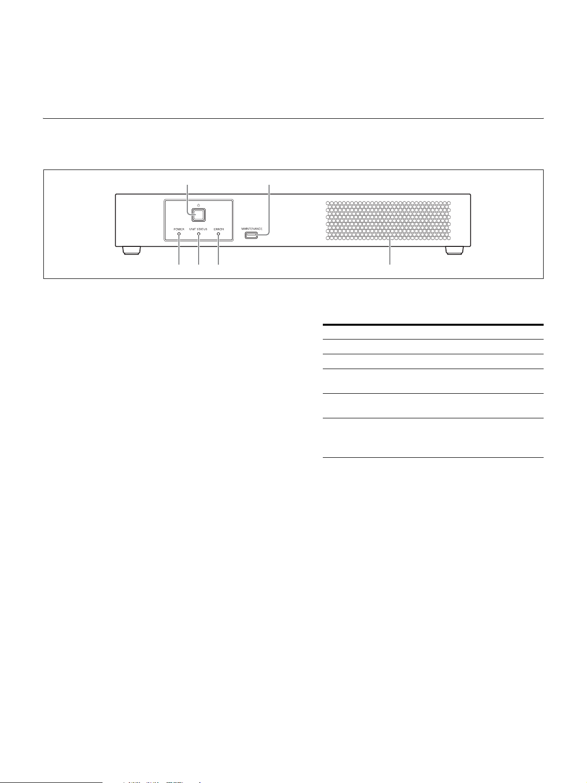
ZRCT-100 Display Controller
Front
This connector is not used for the last display unit in
the daisy-chain connection.
a
fed c
a 1 (power) switch
Turns the display controller on/off.
For details, see “Turning the Power On/Off”
(page 8).
b MAINTENANCE connector
This connector is used for maintenance servicing.
c Intake vent
Do not block the intake vent, as doing so will result in
interior heat buildup which may result in fire or
malfunction.
d ERROR indicator
Blinks when warnings occur, and lights when errors
occur.
b
f POWER indicator
Indicates the power status of the display controller.
Indicator Status
Off The display controller is turned off.
Lit orange The display controller is in standby mode.
Lit green The display controller is turned on (normal
Blinking
green
Lit red The forced standby mode has been entered.
operating status).
The display controller is starting up or
shutting down.
For details, see “Entering the forced standby
mode” (page 14) in the “Troubleshooting.”
For details, see “Troubleshooting” (page 13) and
“Error Codes” (page 15).
e UNIT STATUS indicator
Indicates the power status of the display units.
The indicator lights green when all the display units
that are connected to the display controller according
to the display unit layout settings are turned on.
If any of the display units are turned off according to
the display unit layout settings, the indicator turns off.
For details on the display unit layout settings, consult
your system administrator.
6
 Loading...