

Sony XTV-70 Service manual

XT-V70
D
e.
SERVICE MANUAL
Ver. 1.0 2005.09
• This set is mobile TV tuner for XAV-A1 use only.
• This set includes the TV antenna (VCA-119).
SPECIFICATIONS
Reception format US, Canadian, E (NTSC) models:
Channels US, Canadian, E (NTSC) models:
Power requirement 12 V DC
Power consumption 240 mA
Inputs Video (1)
Outputs Video (1)
Dimensions Approx. 127 × 30 × 107 mm
Mass Approx. 0.38 kg (13 oz)
esign and specifications are subject to change without notic
NTSC
Russian model: SECAM
E (PAL), Australian, Chinese models:
PAL
2-13 (VHF)
14-69 (UHF)
Russian model:
1-12 (VHF)
21-69 (UHF)
E (PAL) model:
2-12 (VHF)
21-69 (UHF)
Australian model:
0-12 (VHF)
28-69 (UHF)
(Monaural)
Chinese model:
1-12 (VHF)
13-57 (UHF)
(negative ground)
Bus (1)
TV antenna (4)
Bus (1)
3
(5 × 1
/16 × 4 1/4 in.)
(W × H × D)
US Model
Canadian Model
E Model
Australian Model
Chinese Model
Russian Model
MOBILE TV TUNER
9-879-878-01
2005I05-1
© 2005.09
Sony Corporation
e Vehicle Company
Published by Sony Engineering Corporation

XT-V70
TABLE OF CONTENTS
1. SERVICING NOTES ................................................ 3
2. GENERAL ................................................................... 4
3. ELECTRICAL ADJUSTMENTS .......................... 7
4. DIAGRAMS
4-1. Block Diagram (Except Russian model) ......................... 9
4-2. Block Diagram (Russian model only) ............................. 10
4-3. Printed Wiring Boards – TV Section (1/2) –
(Except Russian model)................................................... 12
4-4. Printed Wiring Board – TV Section (2/2) –
(Except Russian model)................................................... 13
4-5. Schematic Diagram – TV Section –
(Except Russian model)................................................... 14
4-6. Schematic Diagram – TV Section (1/3) –
(Russian model only)...................................................... 15
4-7. Schematic Diagram – TV Section (2/3) –
(Russian model only)....................................................... 16
4-8. Schematic Diagram – TV Section (3/3) –
(Russian model only)...................................................... 17
4-9. Printed Wiring Boards – TV Section (1/2) –
(Russian model only)....................................................... 18
4-10. Printed Wiring Board – TV Section (2/2) –
(Russian model only)....................................................... 19
5. EXPLODED VIEW ................................................... 27
6. ELECTRICAL PARTS LIST................................ 28
Notes on chip component replacement
• Never reuse a disconnected chip component.
• Notice that the minus side of a tantalum capacitor may be
damaged by heat.
Flexible Circuit Board Repairing
• Keep the temperature of the soldering iron around 270 ˚C
during repairing.
• Do not touch the soldering iron on the same conductor of the
circuit board (within 3 times).
• Be careful not to apply force on the conductor when soldering
or unsoldering.
2
UNLEADED SOLDER
Boards requiring use of unleaded solder are printed with the leadfree mark (LF) indicating the solder contains no lead.
(Caution: Some printed circuit boards may not come printed with
the lead free mark due to their particular size)
: LEAD FREE MARK
Unleaded solder has the following characteristics.
• Unleaded solder melts at a temperature about 40 °C higher
than ordinary solder.
Ordinary soldering irons can be used but the iron tip has to be
applied to the solder joint for a slightly longer time.
Soldering irons using a temperature regulator should be set to
about 350 °C.
Caution: The printed pattern (copper foil) may peel away if
the heated tip is applied for too long, so be careful!
• Strong viscosity
Unleaded solder is more viscou-s (sticky, less prone to flow)
than ordinary solder so use caution not to let solder bridges
occur such as on IC pins, etc.
• Usable with ordinary solder
It is best to use only unleaded solder but unleaded solder may
also be added to ordinary solder.
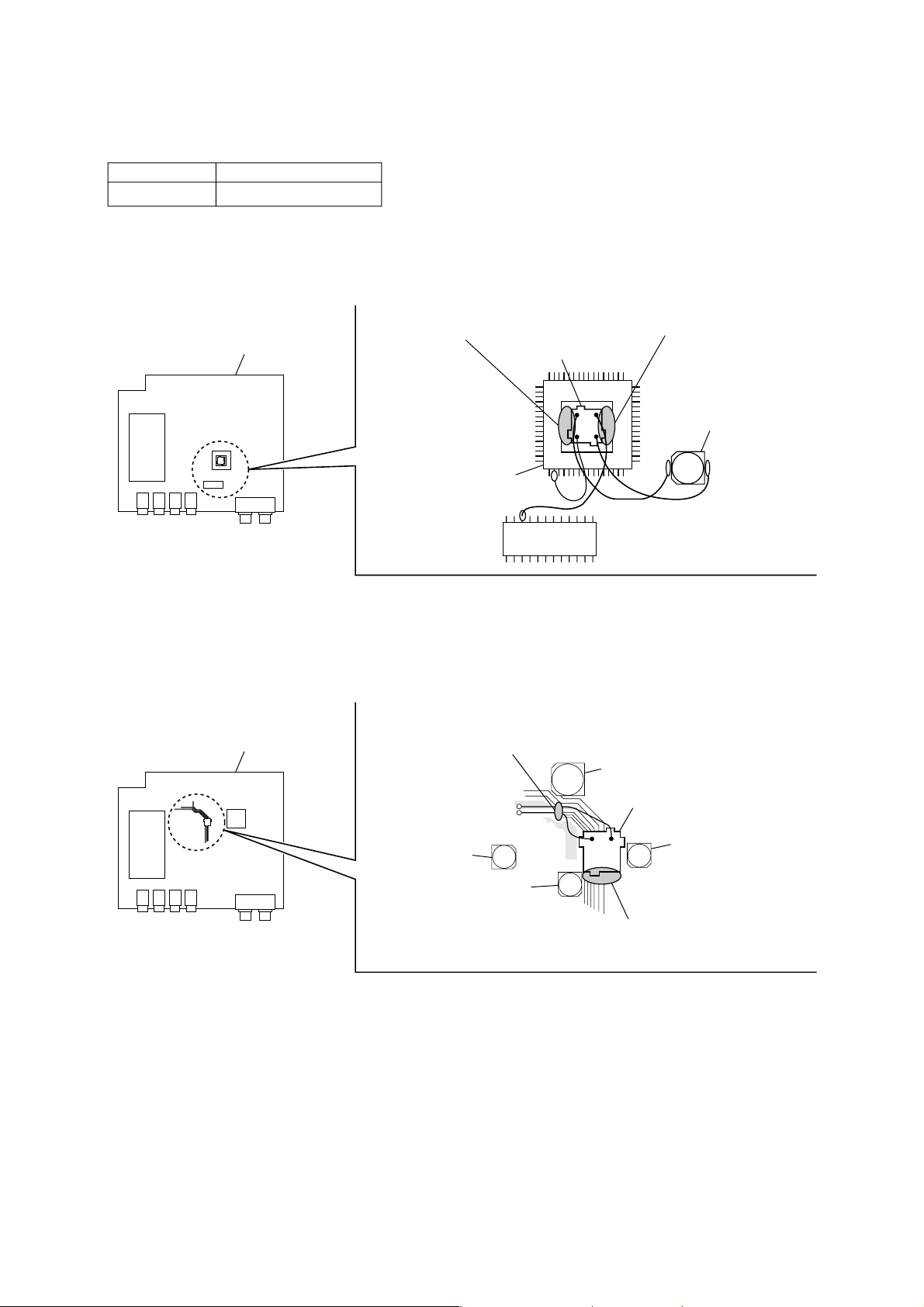
SECTION 1
SERVICING NOTES
NOTES ON REPLACEMENT OF SYNC/TV2 BOARDS
To secure the SYNC/TV2 boards, a special bond is required.
Part. No. Description
7-432-912-48 SONY BOND SC608LV
– SYNC board (Russian model) –
If replacing the SYNC board, disconnect the SYNC board from the TV board,
and clear off the remaining bond with a cutter, etc. and then apply the bond and install new board.
In clearing off the remaining bond with a cutter, take care not to damage the board or mounted parts.
XT-V70
For the bond application locations.
(SONY BOND SC608LV)
TV board
IC301
– TV2 board (except Russian model) –
If replacing the TV2 board, disconnect the TV2 board from the TV board,
and clear off the remaining bond with a cutter, etc. and then apply the bond and install new board.
In clearing off the remaining bond with a cutter, take care not to damage the board or mounted parts.
TV board
For the bond application locations.
(SONY BOND SC608LV)
SYNC board
IC403
For the bond application locations.
(SONY BOND SC608LV)
C105
C330
C47
TV2 board
C153
C6
For the bond application locations.
(SONY BOND SC608LV)
3
XT-V70
SECTION 2
GENERAL
This section is extracted from
instruction manual.
2
3
CONTROL IN
AV Center
AV Center
XAV-A1
AUX 3
VIDEO OUT
TV tuner unit
Tuner de télévision
XT-V70
CONTROL OUT
RCA interconnects (5 m) 2
Interconnexions RCA (5 m) 2
* To the optional back camera or a video
equipment (to AUX 3).
*A une caméra arrière en option ou un
équipement vidéo (à AUX3).
VIDEO IN
TV tuner unit
Tuner de télévision
XT-V70
CONTROL OUT
Bus cable (5.3 m) 1
Câble de bus (5,3 m) 1
VIDEO OUT
CONTROL OUT
Connection box XA-123
(supplied with XAV-A1)
Boite de raccordement XA-123
(fournie avec XAV-A1)
Available only in the USA.
Disponible seulement aux Etats-Unis.
ANT IN
Fuse (0.5 A)
Fusible (0,5 A)
AUX 3
AV Center
AV Center
XAV-A1
XM radio tuner (optional)
XM tuner de radio (en option)
Film antenna 5
Antenne film 5
Antenna input cable 6
Câble d’entrée d’antenne 6
TV antenna amplifier unit 4
Amplificateur d’antenne de télévision 4
To a metal surface of the car
Black
Noir
Red
Rouge
A la surface métallique de la voiture
To the +12 V power terminal which is
energized in the accessory position of the
ignition key switch.
Be sure to connect the black ground lead to
it first.
A la borne d’alimentation +12 V traversee
par le courant a la position accessoire de la
cle de contact.
Raccordez-y bien le fil de mise a la terre noir
en premier.
5
Antenna input cable 6
Câble d’entrée d’antenne 6
6
1
Power supply point
Point d’alimentation
Align the upper edge of the
antenna with this line.
Aligner l’extrémité supérieure de
l’antenne sur cette ligne.
7
Front pillar
Montant avant
Film antenna (left) 5
Antenne film (gauche) 5
Ceramic line
Ligne en
céramique
Temporary fastener
(cellophane tape, etc.)
Fixation temporaire
(ruban adhésif etc.)
Film antenna (right) 5
Antenne film (droite) 5
XAV-A1
Front pillar
Montant avant
Antenna input cable 6
Câble d’entrée d’antenne 6
TV antenna amplifier unit 4
Amplificateur d’antenne de
télévision 4
2
Marking (cellophane tape, etc.)
Marque (ruban adhésif etc.)
Front pillar
Montant avant
4
Hook-and-loop fastener 3
Patins adhésifs 3
On installation surface
Sur la surface d’installation
XT-V70
Hook-and-loop fastener 3
Patins adhésifs 3
8
1
2
3
Marking (cellophane tape, etc.)
Marque (ruban adhésif etc.)
Peel-off tab
Languette d’écaillage
Align the upper edge of the antenna with this line.
Aligner le bord supérieur de l’antenne sur cette ligne.
Spray bottle
Vaporisateur
Marking (cellophane tape, etc.)
Marque (ruban adhésif etc.)
4
Squeegee 8
Raclette 8
4
XT-V70
9
1
2
3
Temporary fastening
(cellophane tape, etc.)
Fixation temporaire
(ruban adhésif etc.)
Power supply point
Point d’alimentation
Peel off the
protective
sheet.
Détachez la
feuille de
protection.
Peel off the
protective
sheet.
Détachez la
feuille de
protection.
Protective sheet
Feuille de protection
Power supply point
Point d’alimentation
Roof lining
Garniture du toit
Temporary fastening
(cellophane tape, etc.)
Fixation temporaire
(ruban adhésif etc.)
qa
TV antenna amplifier unit 4
Amplificateur d’antenne de téléviseur 4
Peel off the protective sheet.
Détachez la feuille de protection.
qs
qd
Antenna input cable (left) 6
Câble d’entrée d’antenne
(gauche) 6
Vehicle ACC power supply
Alimentation ACC du véhicule
Front pillar
Montant avant
Film antenna (left) 5
Antenne film (gauche) 5
Film antenna (right) 5
Antenne film (droite) 5
XAV-A1
TV antenna amplifier unit 4
Amplificateur d’antenne de téléviseur 4
Fold back the floor mat.
Retournez le tapis de plancher.
Antenna contacts
Contacts d’antenne
Spare contact
Contact de rechange
Ground contact
Contact de terre
Front pillar
Montant avant
Antenna input cable (right) 6
Câble d’entrée d’antenne (droit) 6
q;
1
2
3
Grounding tape 7 (peel off the protective sheet.)
Ruban de terre 7 (détachez la feuille de protection.)
Ground contact (peel off the protective sheet.)
Contact de terre (détachez la feuille de protection.)
Antenna cord clamp 9
Serre-fils de cordon d’antenne 9
Antenna cord clamp 9
Serre-fils de cordon d’antenne 9
Antenna input cable (right) 6
Câble d’entrée d’antenne (droit) 6
TV antenna amplifier unit 4
Amplificateur d’antenne de
téléviseur 4
Antenna cord clamp 9
4
Serre-fils de cordon
d’antenne 9
Antenna cord clamp 0
Serre-fils de cordon
d’antenne 0
IMPORTANT CAUTION!
Do not route the cable near the pedals!
PRECAUTION IMPORTANTE!
N’acheminez pas le câble près des pédales!
Antenna input cable (left) 6
Câble d’entrée d’antenne (gauche) 6
5
XT-V70
Attach the power supply terminal to the film antenna
5 (9)
1 Remove the power supply point protective sheet from the
film antenna (9-1).
The color of the protective sheet is used to distinguish the left
and right antennas
The right antenna (as seen from inside the car) has a blue
protective sheet, and the left antenna has a white protective
sheet. Take care to mount the antennas on the proper side of the
car.
2 Attach the antenna input cable 6 to the film antenna power
supply terminals (9-2).
•The same type of cable is used for both the left and right
antennas.
•Temporarily fastening the cable near the ground
connection with cellophane tape will make the procedure
easier.
Connecting to the power supply terminals
Align the protrusions on the power supply terminals with the
arrows v on the film antenna and fasten in place.
3 Pass the antenna input cable 6 through the roof lining
(inner roof panel) (9-3).
Notes
• Pull the roof lining down slightly and thread the cable under it.
• Take care not to pull too hard on the lining and bend it out of
shape.
• Perform this step while holding on to the power supply point to
avoid putting stress on that point.
• Route the antenna input cable carefully to avoid pulling excessively
on, applying stress to, or kinking the cable.
Route the antenna input cable 6 (0)
1 Apply the grounding tape 7 to the car body (0-1).
Apply the grounding tape to the metal of the car body, in a
position where it can contact the ground contact on the
antenna input cable.
Notes
• Carefully wipe away any dirt on the attachment surface.
• Be sure to stick the grounding tape completely to a flat, metal
part of the car body. Do not apply the grounding tape to a
place that is not flat, or over a clip or screw hole. Do not scrape
off the finish on the car body.
2 Affix the ground contact on the antenna input cable to the
grounding tape 7.
Peel off the protective sheet from the ground contact and
stick it completely to the grounding tape. Make sure that no
portion of the ground contact protrudes beyond the
grounding tape, and that there is no part of the ground
contact which is not firmly stuck to the grounding tape.
3 Route the antenna input cable, using the supplied antenna
cord clamp 9 to hold it in place (0-2, 3, 4).
Route the cable so that it will be completely covered when
the front pillar molding is replaced.
Important note
Use tape or other fasteners to route the cables such that they
cannot interfere with vehicle operation. Do not wrap the cables
around the steering column, gear shift lever, brake pedal, etc.
Mount the TV antenna amplifier unit 4 (qa)
1 Mount the TV antenna amplifier unit near the floor in the
foot area in front of the passenger’s seat. (Be sure to wipe
away any dirt on the mounting surface.)
Important note
It would be extremely dangerous if the TV antenna amplifier unit
were to get stuck underneath the brake pedal. Be sure to mount
the amplifier on the passenger’s side.
2 Connect the grounding cable from the TV antenna amplifier
unit to a metal part of the car body where it can make a good
ground contact.
3 Connect the antenna input cables to the TV antenna
amplifier unit according to the markings on the amplifier (1,
2, 3, 4, TV).
Connect the TV tuner unit and the car’s ACC power
supply (qs)
1 Connect the antenna terminal (L-type) on the TV antenna
amplifier unit 4 to the TV tuner unit.
2 Connect the accessory power supply terminal to the car’s
ACC power supply.
•Connect the ACC power supply cord from the TV tuner
unit to the spare contact.
•Do not connect directly to the battery.
Replace the front pillar molding
Fasten cords out of the way (qd)
Alignment marks
(protrusions)
Power supply terminals
Alignment marks
(arrows v)
Precautions
•This unit is designed for negative ground 12 V DC systems only.
•Do not get the wires under a screw, or caught in moving parts
(e.g. seat railing).
•Before making connections, turn the car ignition off to avoid
short circuits.
•Connect the red power input leads only after all other leads have
been connected.
•Run all ground wires to a common ground point.
Fuse replacement
When replacing the fuse, be sure to use one matching the
amperage rating stated on the original fuse. If the fuse blows,
check the power connection and replace the fuse. If the fuse blows
again after replacement, there may be an internal malfunction. In
such a case, consult your nearest Sony dealer.
Connection example (2)
Connection diagram (3)
Installing the TV tuner unit (4)
Notes
• Ensure that the mounting surface is clean.
• Do not install the TV tuner unit
– in locations subject to high temperatures.
– in locations subject to direct sunlight, warm air from heater
outlets, or other locations that can get hot.
• When attaching the hook-and-loop fastener to the bottom of the TV
tuner unit, do not cover the model name plate in the center.
Keep the units and connection cables apart.
The AV Center main unit, the monitor, TV tuner unit, and RCA
interconnects should not be in close proximity. Otherwise noise
interference may affect the TV picture.
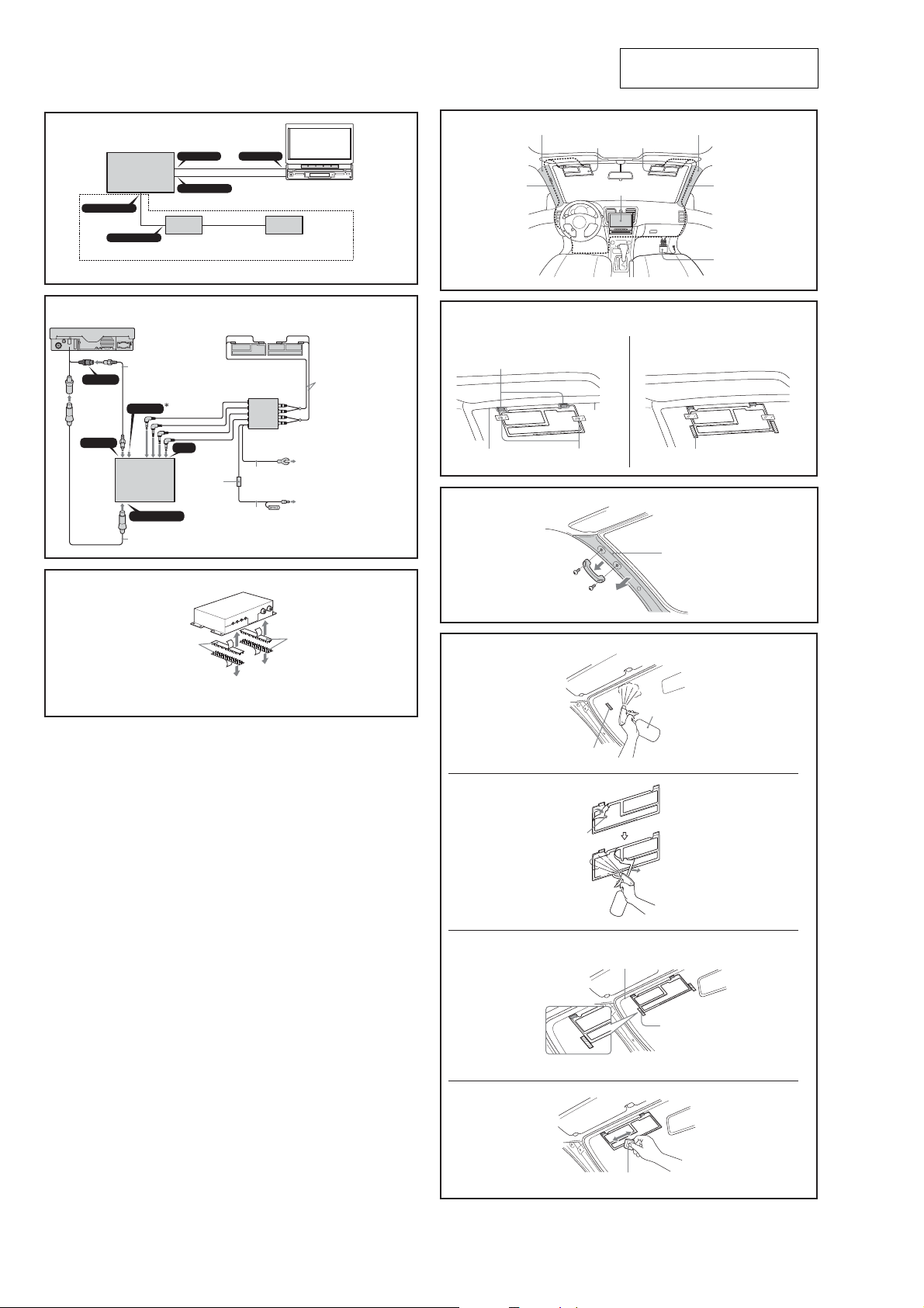
Mounting the TV antenna
Mount the film antenna 5 to the car and connect the TV tuner
unit.
For directions on connecting the TV tuner unit, see also
6
“Connection diagram (3)”.
Before mounting
•It may not be possible to mount the antenna on some cars.
- In cars with glass that does not transmit radio waves (infrared
reflecting glass, insulated glass, glass that is opaque to
electromagnetic waves, etc.), the signal reception will be
extremely poor.
- The antenna cannot be mounted in cars which have airbags in
the front pillars.
•Mount the antenna to the front window, in the specified location
and according to the specified dimensions.
- The supplied film antenna is designed for attaching only to the
front window. If attached to the rear window or elsewhere in
the car, the signal reception may be extremely poor.
Notes
• Once you have mounted the film antenna, do not attempt to remove
it and attach it again, as the adhesive will be considerably weakened.
Be sure to temporarily fasten the cable and antenna in place and
check that the cable has sufficient play before permanently attaching.
• During the mounting procedure, it will be necessary to remove the
front pillar molding to attach a ground wire.
When performing the installation yourself, if you decide it is too
difficult to remove the front pillar molding, please contact your
dealer for assistance. (Note that your dealer may charge a fee for
their assistance.)
Required items
Have the following items handy before beginning the mounting
procedure.
•Tools (Philips screwdriver, etc.)
•Cellophane tape
•Scissors
•Spray bottle (fill with 500 ml water and one or two drops of
detergent)
•Paper towels
Note
Mount the film antennas to the inside of the front window. Do not
mount the antennas anywhere other than the location described here.
Before attaching
Using the supplied cleaning cloth qa to wipe away any oil, wax, or dust
tat may be on the window.
Fuse (0.5 A)
TV antenna amplifier unit 4
Mounting position (5)
Installation complete
Film antenna mounting procedure
Check the film antenna 5 mounting position (6)
1 Align the film antenna power supply point with the lower
edge of the window’s ceramic line and fasten temporarily in
place with cellophane tape (6-1).
Do not remove the adhesive backing from the antenna yet.
The figure shows the results of this step, for the left antenna.
Temporarily position the right antenna in the same manner.
2 Mark the left and right sides of the film antenna, using
cellophane tape, etc (6-2).
Remove the inner molding from the front pillars on
both sides of the front window (7)
The figure shows an example of a car, such as a sedan or SUV,
which as a handle mounted on the front pillar.
Notes
• The molding on the front pillar will be fastened in place with clips or
screws. When removing it, take care not to damage or deform it.
• When performing the installation yourself, if you decide it is too
difficult to remove the front pillar molding, please contact your
dealer for assistance. (Note that your dealer may charge a fee for
their assistance.)
Attach film antenna 5 (8)
Before attaching
• Remove the film antenna, which you previously fastened temporarily
in place, before beginning these steps.
• Cover the dashboard with a cloth to protect it from the water and
detergent.
•Clean the front window well to remove any dirt, oil, or anti-fogging
agent before beginning these steps.
1 Using a spray bottle, wet the inside of the front window well
with a mild detergent solution. The optimal solution is 500 ml
of water with one or two drops of detergent (8-1). (Pure
water will not work well for making fine adjustments.)
2 Remove the clear backing from the film antenna. Using the
spray bottle, wet the exposed surface well with the mild
detergent solution (8-2).
•Grasp the peel-off tab and peel the clear backing off slowly.
•Do not remove the protective sheet from the other side (the
side that faces the inside of the car) yet. You will remove that
sheet in step 8-4.
•Take care not to get dirt or fingerprints on the exposed
surface of the film antenna.
When attaching the film antenna
• Position the antenna vertically by aligning the upper edge of the
antenna with the lower edge of the ceramic line. Position it
horizontally by aligning the edges with the marking (cellophane
tape, etc.) that you previously placed on the window.
• Do not let the front window get dry as you are working. Spray it
again with the detergent solution as needed.
• Until the front window dries, you can slide the antenna to adjust
its position.
• When you have the antenna positioned where you want it,
remove the markings.
3 Stick the film antenna to the front window (8-3).
4 Use the supplied squeegee 8 to make sure the film antenna is
well attached to the window (8-4).
•Hold the antenna so it does not move while using the
squeegee.
•Work from the center of the antenna outward.
•Work the squeegee along the length of the antenna, pushing
out air bubbles to obtain a good seal.
•Do not rub the antenna too hard.
Note
Make sure that the film antenna is completely dry before
continuing with the mounting procedure. Continuing before the
antenna is dry may cause it to come off the window.
5 Use paper towels to wipe away the excess detergent solution
and dry the antenna well.
We recommend you let the antenna dry for 3-4 hours.
Do not try to rush the drying process by using a hair dryer or
other heater. Doing so may damage the film antenna.
Turn over. t

SECTION 3
T
r
+
–
TV SSG
CONTROL OUT
connector
(CP101)
Regulated
Power Supply
14.4V
XAV-A1
XT-V70
GND
B+
ANT IN 1 jack
(JK11)
Center-tap
of SVR31
oscilloscope
(DC range)
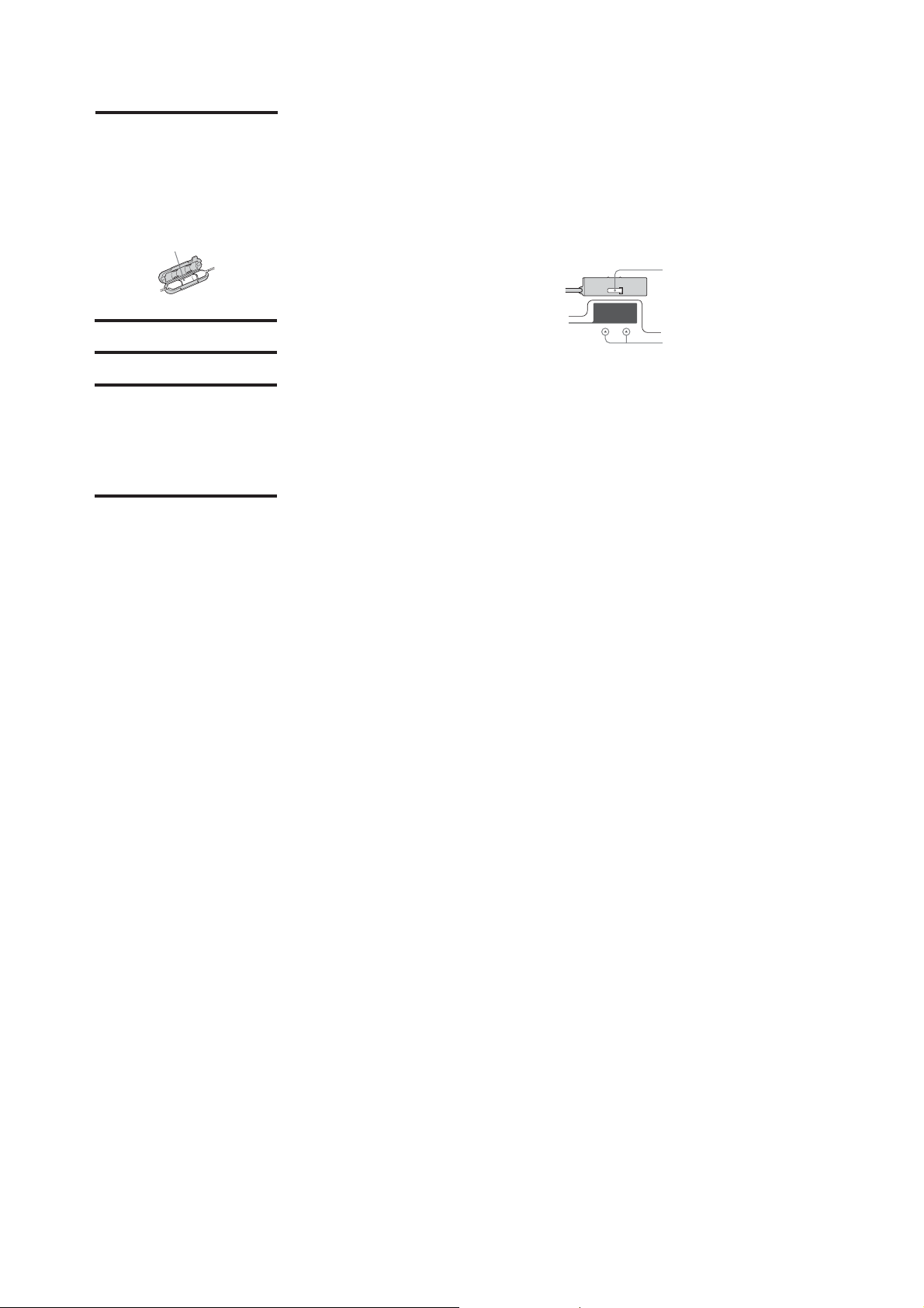
ELECTRICAL ADJUSTMENTS
XT-V70
AUDIO OUTPUT LEVEL ADJUSTMENT
Setting:
ANT IN 1 jack
(JK11)
TV SSG
Regulated
Power Supply
14.4V
XT-V70
XAV-A1
B+
GND
Procedure:
1. Connect the XT-V70 to the XAV-A1 and turn the power on.
2. Set the TV mode and set the reception channel to the VHF
band 2ch (except Russian models) or the VHF band 1ch
(Russian model).
3. Connect a TV SSG to the ANT IN 1 (JK11) jack on the TV
board and input following color bar signal.
US, Canadian and E (NTSC) models:
USA 2 ch, 60 dBuvemf, MONO signal
(f.v: 55.25 kHz, f.a: 59.75 kHz, 25kHzdev. 400 Hz)
Australian, Chinese and E (PAL) models:
CHINA 2 ch, 60 dBuvemf, MONO signal
(f.v: 55.75 kHz, f.a: 64.25 kHz, 50kHzdev. 400 Hz)
Russian model:
OIR 1 ch, 60 dBuvemf, MONO signal
(f.v: 49.75 kHz, f.a: 56.25 kHz, 50kHzdev. 400 Hz)
4. Connect a digital voltmeter to the TP51B on the TV board.
5. Adjust the SVR100 (except Russian models) or SVR221
(Russian model) on the TV board so that the value of digital
voltmeter becomes 700 mV ± 10 mV.
TP51B
digital
voltmeter
CONTROL OU
connector
(CP101)
VIDEO OUTPUT LEVEL ADJUSTMENT
(Russian model only)
Setting:
Procedure:
1. Connect the XT-V70 to the XAV-A1 and turn the power on.
2. Set the TV mode and set the reception channel to the VHF
band 1ch.
3. Connect a TV SSG to the ANT IN 1 (JK11) jack on the TV
board and input white (100%) signal.
4. Set the TV-RF output to the 60 dBuv.
5. Connect a oscilloscope to the center-tap of SVR31 on the TV
board.
6. Adjust the SVR31 on the TV board so that the value of
oscilloscope becomes 1 Vp-p ± 0.5 Vp-p.
Adjustment and Connection Location: TV board
(See page 8)
Adjustment and Connection Location: TV board
(See page 8)
DIVERSITY VCO ADJUSTMENT
Setting:
frequency counte
TV board
IC11 or IC81 pin
Procedure:
1. Connect the XT-V70 to the XAV-A1 and turn the power on.
2. Connect the U1 or U2 to the GND on the TV board to set the
test mode.
7
3. Connect a frequency counter to the IC11 (except Russian
models) or IC81 (Russian model) pin 7 on the TV board.
4. Adjust the CT11 (except Russian models) or CT81 (Russian
model) on the TV board so that the value of frequency counter
becomes 15.73 kHz ± 0.2 kHz (NTSC) or 15.62 kHz ± 0.2
kHz (PAL).
Adjustment and Connection Location: TV board
+
–
(See page 8)
7

XT-V70
Adjustment and Connection Location:
Except Russian model
– TV Board (Component Side) –
CT11
Diversity VCO
Adjustment
11224
IC11
13
Russian model only
– TV Board (Conductor Side) –
TP51B
SVR100
Audio Output Level
Adjustment
– TV Board (Component Side) –
SVR221
Audio Output Level
Adjustment
CT81
Diversity VCO
Adjustment
11224
IC81
13
SVR31
Video Output Level
Adjustment
– TV Board (Conductor Side) –
TP51B
8

SECTION 4
DIAGRAMS
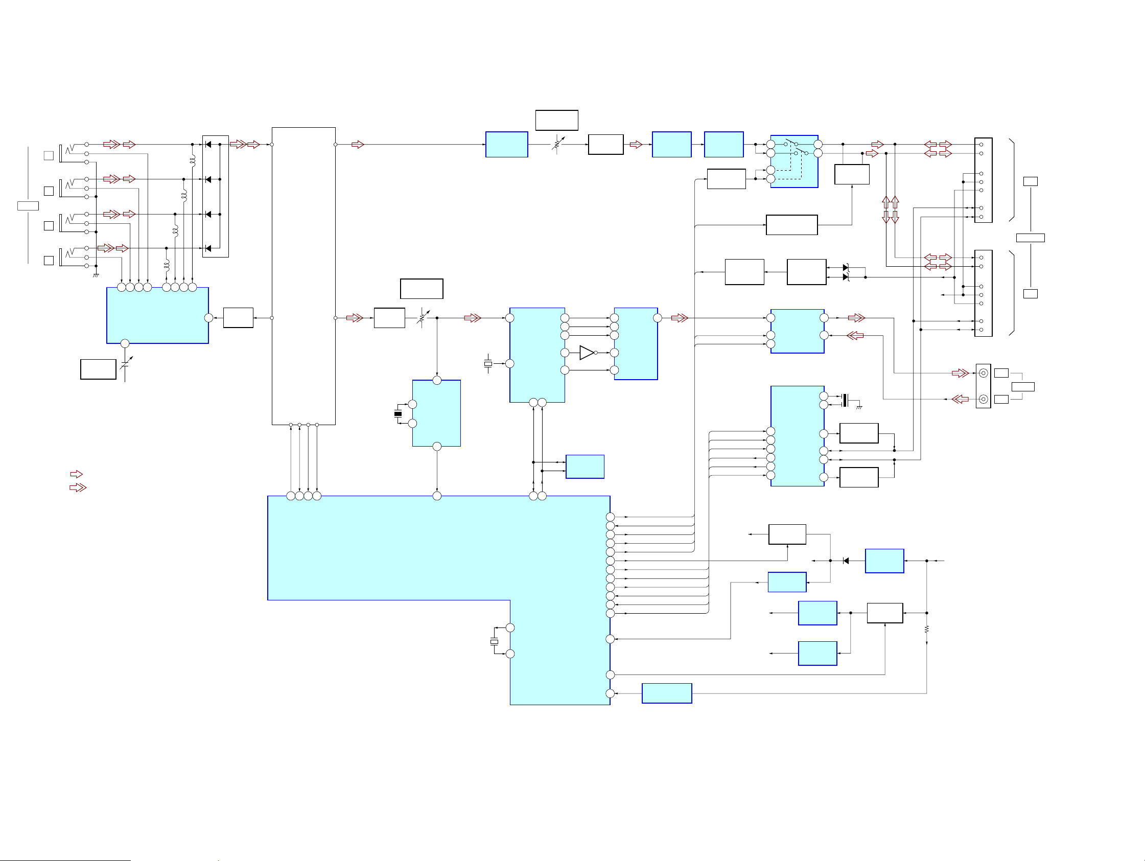
4-1. BLOCK DIAGRAM (Except Russian model)
XT-V70
ANT IN
JK11
1
JK12
2
JK13
3
JK14
4
DIVERSITY ANTENNA
CONTROL
IC11
• SIGNAL PATH
: AUDIO
: VIDEO
CT11
DIVERSITY
VCO
12 1011 9 13 1514 16
ANT4
ANT3
ADET4
CREF
4
ADET3
ADET2
ADET1
ANT2
VIDEO IN
(E (PAL), Australian, Chinese)
1
14
9
TV TUNER
RF IN
VIDEO
OUT2
NICAM SW
SCL
341213
SCL
TU11
SDA
SDA
AUDIO
OUT
VIDEO
OUT1
SMETER
SD OUT
SD
SMETER
11
15
SYSTEM CONTROLLER
IC151
X151
6MHz
BUFFER
Q15
NOISE
CANCELLER
IC1
X91
500kHz
40
41
ANTENNA
SWITCH
D11-14
ANT1
NICAM SWITCH
BUFFER
24
Q12
Q13, Q14
53
56 49 13 32 30 29
SW1
SW2
AUDIO OUTPUT
VIDEO OUTPUT
LEVEL
VCO IN
10
VCO OUT
11
X2
X1
SVR100
LEVEL
2
VIDEO IN
DET OUT
8
VSD
SYNC
DETECT
IC91
AUDIO_OFF
V_CONT1
V_CONT2
MUTE
J1850+B
J1850AD
J1850CLK
J1850RX
J1850TX
J1850INT
J1850RES
RESET
POWER
BATT
BUFFER
Q56
51
44
CE
54
55
23
21
20
19
18
46
22
36
43
AUDIO SWITCH
HIGH-PASS
FILTER
IC51 (1/2)
AUDIO_OFF
MUTE
CE
V-CONT1
V-CONT2
AUDIO_OFF
CE
V_CONT1
V_CONT2
3
8
MUTE
J1850AD
J1850CLK
J1850RX
J1850TX
J1850INT
J1850RES
BATTERY DETECT
IC102
LOW-PASS
FILTER
IC51 (2/2)
LEVEL SHIFT
Q51, 52
ACCESSORY
J1850AD
J1850CLK
J1850RX
J1850TX
J1850INT
J1850RES
J-BUS B+
DETECT
Q107
V8
V5
IC52
4
1
5
13
MUTING CONTROL
Q54
ACCESSORY
CHECK
Q105, 106
VIDEO SWITCH
IC53
1
VIN1 VOUT
SW1
2
4
15
16
20
21
22
23
B+ SWITCH
VIN2
CTL3
J-BUS CONTROL
IC181
OSC1
OSC0
AD
BO–
CLK
RX
BUS–
TX
BUS+
INT
RES
BO+
Q551, 552
VDD
RESET
IC182
REGULATOR
REGULATOR
3
2
+8V
IC103
+5V
IC104
13
14
7
3
2
3
4
5
MUTING
Q53, 59
DZ102
DZ103
X181
10MHz
BUS DRIVER
Q183
BUS DRIVER
Q184
D101
+5.3V
REGULATOR
IC101
B+ SWITCH
Q103, 104
BU
CP101
7
LCH
8
RCH
9
BU
10
11
1
2
CP102
7
8
9
10
11
1
2
CP51
BU
BU
ACC
BUS–
BUS+
LCH
RCH
BU
BU
ACC
BUS–
BUS+
OUT
IN
OUT
CONTROL
IN
VIDEO
XT-V70
99
XT-V70
4-2. BLOCK DIAGRAM (Russian model only)
ANT IN
JK11
1
JK12
2
JK13
3
JK14
4
DIVERSITY ANTENNA
CONTROL
IC81
• SIGNAL PATH
CT81
DIVERSITY
VCO
: AUDIO
: VIDEO
12 1011 9 13 1514 16
ANT4
ANT3
ADET4
CREF
4
ADET3
ADET2
ADET1
ANT2
VIDEO IN
ANT1
ANTENNA
SWITCH
D11-14
24
BUFFER
Q81
TV TUNER
TU31
1
RF IN
14
VIDEO
OUT2
SCL
SDA
341213
49 13 32 30 29
SCL
SDA
AUDIO
OUT
VIDEO
OUT1
SMETER
SD OUT
SD
SMETER
11
15
BUFFER
X451
500kHz
Q31
SVR31
VIDEO OUTPUT
LEVEL
VIDEO IN
10
VCO IN
VCO OUT
11
DET OUT
SYSTEM CONTROLLER
SVR221
AUDIO OUTPUT
LEVEL
NOISE
CANCELLER
IC201
SECAM DECODER
IC301
41
TV IN
X301
4.43361MHz
34
XTAL
2
SYNC
DETECT
IC451
8
VSD
IC501
X501
6MHz
26
12
40
X2
41
X1
INT MON
FSC OUT
SDA27SCL
14
SSCL
SSDA
14
R
15
G
16
B
18
29
EEPROM
IC401
AUDIO_OFF
V_CONT1
V_CONT2
MUTE
J1850+B
J1850AD
J1850CLK
J1850RX
J1850TX
J1850INT
J1850RES
RESET
POWER
BATT
BUFFER
Q221
RGB-TV ENCODER
2
3
4
10
6
51
44
CE
54
55
3
23
21
20
19
18
46
22
36
8
43
RIN
GIN
BIN
SYNCIN
FSCIN
IC403
VOUT
BATTERY DETECT
HIGH-PASS
FILTER
IC221 (1/2)
AUDIO_OFF
20
AUDIO_OFF
V_CONT1
V_CONT2
MUTE
IC603
CE
J1850AD
J1850CLK
J1850RX
J1850TX
J1850INT
J1850RES
LOW-PASS
IC221 (2/2)
LEVEL SHIFT
MUTE
CE
V-CONT1
V-CONT2
FILTER
Q254, 255
ACCESSORY
J1850AD
J1850CLK
J1850RX
J1850TX
J1850INT
J1850RES
J-BUS B+
DETECT
Q655
AUDIO SWITCH
IC251
4
1
5
13
MUTING CONTROL
Q253
ACCESSORY
VIDEO SWITCH
IC452
1
VIN1 VOUT
2
SW1
4
CTL3
J-BUS CONTROL
IC551
15
AD
16
CLK
20
RX
21
TX
22
INT
23
RES
B+ SWITCH
Q551, 552
RESET
IC502
V8
V5
CHECK
Q653, 654
VIN2
OSC1
OSC0
BO–
BUS–
BUS+
BO+
VDD
REGULATOR
IC651
REGULATOR
IC652
+8V
+5V
CP702
CP701
CP452
7
LCH
8
RCH
9
BU
10
11
1
2
7
8
9
10
11
1
2
BU
ACC
BUS–
BUS+
LCH
RCH
BU
BU
ACC
BUS–
BUS+
OUT
IN
OUT
CONTROL
IN
VIDEO
3
2
MUTING
Q251, 252
DZ652
13
14
7
3
2
3
4
5
DZ653
X551
10MHz
BUS DRIVER
Q554
BUS DRIVER
Q553
D601
+5.3V
REGULATOR
IC602
B+ SWITCH
Q651, 652
BU
BU
XT-V70
1010
XT-V70
Note on Printed Wiring Boards:
• X : parts extracted from the component side.
• Y : parts extracted from the conductor side.
• x : parts mounted on the conductor side.
• : Carbon pattern.
(The other layers' patterns are not indicated.)
Caution:
Pattern face side: Parts on the pattern face side seen from
(Conductor Side) the pattern face are indicated.
Parts face side: Parts on the parts face side seen from
(Component Side) the parts face are indicated.
Note on Schematic Diagram:
• All capacitors are in µF unless otherwise noted. (p: pF) 50 WV or
less are not indicated except for electrolytics and tantalums.
• All resistors are in Ω and 1/
• C : panel designation.
• H : adjustment for repair.
• Power supply is supplied from the AV Center (XA V -A1) in TV model.
• Voltages and waveforms are dc with respect to ground under no-
signal conditions.
no mark : TV
• Voltages are taken with a VOM (Input impedance 10 MΩ).
Voltage variations may be noted due to normal production tolerances.
• Waveforms are taken with a oscilloscope.
Voltage variations may be noted due to normal production tolerances.
• Circled numbers refer to waveforms.
• Signal path.
F : AUDIO
L : VIDEO
• Abbreviation
AUS: Australian model
CH : Chinese model
CND : Canadian model
RU : Russian model
4
W or less unless otherwise specified.
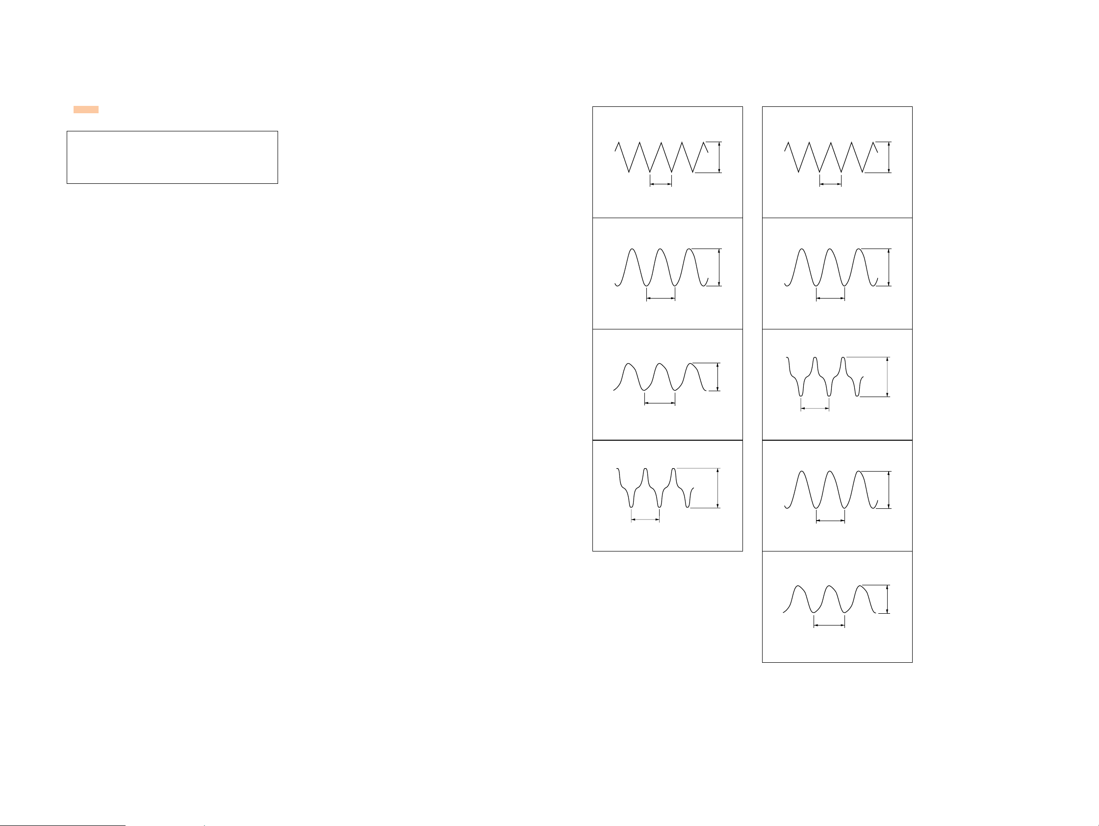
• Waveforms
– TV Board – (except Russian model) – TV Board – (Russian model only)
IC11 4 (CREF)
1
500 mV/DIV, 5 µs/DIV
IC151 ra (X1)
2
IC181 qd (OSC1)
3
2 Vp-p
2.6 µs
4.2 Vp-p
166 ns
1 V/DIV, 100 ns/DIV
IC81 4 (CREF)
qa
2.6 µs
500 mV/DIV, 5 µs/DIV
IC301 ef (XTAL)
qs
224 ns
200 mV/DIV, 200 ns/DIV
IC451 qa (VCO OUT)
qd
2 Vp-p
500 mVp-p
2 V/DIV, 200 ns/DIV
IC91 qa (VCO OUT)
5
2 µs
500 mV/DIV, 5 µs/DIV
100 ns
5.1 Vp-p
1.5Vp-p
500 mV/DIV, 5 µs/DIV
IC501 ra (X1)
qf
IC551 qd (OSC1)
qg
1.4Vp-p
2 µs
4.3 Vp-p
167 ns
1 V/DIV, 100 ns/DIV
5.2 Vp-p
100 ns
2 V/DIV, 200 ns/DIV
XT-V70
1111
 Loading...